EP3326443B1 - Elektrische anlage - Google Patents
Elektrische anlage Download PDFInfo
- Publication number
- EP3326443B1 EP3326443B1 EP17203143.7A EP17203143A EP3326443B1 EP 3326443 B1 EP3326443 B1 EP 3326443B1 EP 17203143 A EP17203143 A EP 17203143A EP 3326443 B1 EP3326443 B1 EP 3326443B1
- Authority
- EP
- European Patent Office
- Prior art keywords
- rotational speed
- deceleration
- work
- travel
- motor
- Prior art date
- Legal status (The legal status is an assumption and is not a legal conclusion. Google has not performed a legal analysis and makes no representation as to the accuracy of the status listed.)
- Active
Links
Images




Classifications
-
- A—HUMAN NECESSITIES
- A01—AGRICULTURE; FORESTRY; ANIMAL HUSBANDRY; HUNTING; TRAPPING; FISHING
- A01D—HARVESTING; MOWING
- A01D34/00—Mowers; Mowing apparatus of harvesters
- A01D34/006—Control or measuring arrangements
-
- A—HUMAN NECESSITIES
- A01—AGRICULTURE; FORESTRY; ANIMAL HUSBANDRY; HUNTING; TRAPPING; FISHING
- A01D—HARVESTING; MOWING
- A01D34/00—Mowers; Mowing apparatus of harvesters
- A01D34/01—Mowers; Mowing apparatus of harvesters characterised by features relating to the type of cutting apparatus
- A01D34/412—Mowers; Mowing apparatus of harvesters characterised by features relating to the type of cutting apparatus having rotating cutters
- A01D34/63—Mowers; Mowing apparatus of harvesters characterised by features relating to the type of cutting apparatus having rotating cutters having cutters rotating about a vertical axis
- A01D34/67—Mowers; Mowing apparatus of harvesters characterised by features relating to the type of cutting apparatus having rotating cutters having cutters rotating about a vertical axis hand-guided by a walking operator
- A01D34/68—Mowers; Mowing apparatus of harvesters characterised by features relating to the type of cutting apparatus having rotating cutters having cutters rotating about a vertical axis hand-guided by a walking operator with motor driven cutters or wheels
- A01D34/6806—Driving mechanisms
-
- A—HUMAN NECESSITIES
- A01—AGRICULTURE; FORESTRY; ANIMAL HUSBANDRY; HUNTING; TRAPPING; FISHING
- A01D—HARVESTING; MOWING
- A01D34/00—Mowers; Mowing apparatus of harvesters
- A01D34/01—Mowers; Mowing apparatus of harvesters characterised by features relating to the type of cutting apparatus
- A01D34/412—Mowers; Mowing apparatus of harvesters characterised by features relating to the type of cutting apparatus having rotating cutters
- A01D34/63—Mowers; Mowing apparatus of harvesters characterised by features relating to the type of cutting apparatus having rotating cutters having cutters rotating about a vertical axis
- A01D34/67—Mowers; Mowing apparatus of harvesters characterised by features relating to the type of cutting apparatus having rotating cutters having cutters rotating about a vertical axis hand-guided by a walking operator
- A01D34/68—Mowers; Mowing apparatus of harvesters characterised by features relating to the type of cutting apparatus having rotating cutters having cutters rotating about a vertical axis hand-guided by a walking operator with motor driven cutters or wheels
- A01D34/69—Mowers; Mowing apparatus of harvesters characterised by features relating to the type of cutting apparatus having rotating cutters having cutters rotating about a vertical axis hand-guided by a walking operator with motor driven cutters or wheels with motor driven wheels
-
- A—HUMAN NECESSITIES
- A01—AGRICULTURE; FORESTRY; ANIMAL HUSBANDRY; HUNTING; TRAPPING; FISHING
- A01D—HARVESTING; MOWING
- A01D34/00—Mowers; Mowing apparatus of harvesters
- A01D34/01—Mowers; Mowing apparatus of harvesters characterised by features relating to the type of cutting apparatus
- A01D34/412—Mowers; Mowing apparatus of harvesters characterised by features relating to the type of cutting apparatus having rotating cutters
- A01D34/63—Mowers; Mowing apparatus of harvesters characterised by features relating to the type of cutting apparatus having rotating cutters having cutters rotating about a vertical axis
- A01D34/76—Driving mechanisms for the cutters
- A01D34/78—Driving mechanisms for the cutters electric
-
- A—HUMAN NECESSITIES
- A01—AGRICULTURE; FORESTRY; ANIMAL HUSBANDRY; HUNTING; TRAPPING; FISHING
- A01D—HARVESTING; MOWING
- A01D34/00—Mowers; Mowing apparatus of harvesters
- A01D34/01—Mowers; Mowing apparatus of harvesters characterised by features relating to the type of cutting apparatus
- A01D34/412—Mowers; Mowing apparatus of harvesters characterised by features relating to the type of cutting apparatus having rotating cutters
- A01D34/63—Mowers; Mowing apparatus of harvesters characterised by features relating to the type of cutting apparatus having rotating cutters having cutters rotating about a vertical axis
- A01D34/81—Casings; Housings
-
- A—HUMAN NECESSITIES
- A01—AGRICULTURE; FORESTRY; ANIMAL HUSBANDRY; HUNTING; TRAPPING; FISHING
- A01D—HARVESTING; MOWING
- A01D69/00—Driving mechanisms or parts thereof for harvesters or mowers
- A01D69/02—Driving mechanisms or parts thereof for harvesters or mowers electric
-
- B—PERFORMING OPERATIONS; TRANSPORTING
- B60—VEHICLES IN GENERAL
- B60L—PROPULSION OF ELECTRICALLY-PROPELLED VEHICLES; SUPPLYING ELECTRIC POWER FOR AUXILIARY EQUIPMENT OF ELECTRICALLY-PROPELLED VEHICLES; ELECTRODYNAMIC BRAKE SYSTEMS FOR VEHICLES IN GENERAL; MAGNETIC SUSPENSION OR LEVITATION FOR VEHICLES; MONITORING OPERATING VARIABLES OF ELECTRICALLY-PROPELLED VEHICLES; ELECTRIC SAFETY DEVICES FOR ELECTRICALLY-PROPELLED VEHICLES
- B60L50/00—Electric propulsion with power supplied within the vehicle
- B60L50/50—Electric propulsion with power supplied within the vehicle using propulsion power supplied by batteries or fuel cells
- B60L50/52—Electric propulsion with power supplied within the vehicle using propulsion power supplied by batteries or fuel cells characterised by DC-motors
-
- A—HUMAN NECESSITIES
- A01—AGRICULTURE; FORESTRY; ANIMAL HUSBANDRY; HUNTING; TRAPPING; FISHING
- A01D—HARVESTING; MOWING
- A01D2101/00—Lawn-mowers
-
- B—PERFORMING OPERATIONS; TRANSPORTING
- B60—VEHICLES IN GENERAL
- B60L—PROPULSION OF ELECTRICALLY-PROPELLED VEHICLES; SUPPLYING ELECTRIC POWER FOR AUXILIARY EQUIPMENT OF ELECTRICALLY-PROPELLED VEHICLES; ELECTRODYNAMIC BRAKE SYSTEMS FOR VEHICLES IN GENERAL; MAGNETIC SUSPENSION OR LEVITATION FOR VEHICLES; MONITORING OPERATING VARIABLES OF ELECTRICALLY-PROPELLED VEHICLES; ELECTRIC SAFETY DEVICES FOR ELECTRICALLY-PROPELLED VEHICLES
- B60L2210/00—Converter types
- B60L2210/20—AC to AC converters
-
- Y—GENERAL TAGGING OF NEW TECHNOLOGICAL DEVELOPMENTS; GENERAL TAGGING OF CROSS-SECTIONAL TECHNOLOGIES SPANNING OVER SEVERAL SECTIONS OF THE IPC; TECHNICAL SUBJECTS COVERED BY FORMER USPC CROSS-REFERENCE ART COLLECTIONS [XRACs] AND DIGESTS
- Y02—TECHNOLOGIES OR APPLICATIONS FOR MITIGATION OR ADAPTATION AGAINST CLIMATE CHANGE
- Y02T—CLIMATE CHANGE MITIGATION TECHNOLOGIES RELATED TO TRANSPORTATION
- Y02T10/00—Road transport of goods or passengers
- Y02T10/60—Other road transportation technologies with climate change mitigation effect
- Y02T10/70—Energy storage systems for electromobility, e.g. batteries
-
- Y—GENERAL TAGGING OF NEW TECHNOLOGICAL DEVELOPMENTS; GENERAL TAGGING OF CROSS-SECTIONAL TECHNOLOGIES SPANNING OVER SEVERAL SECTIONS OF THE IPC; TECHNICAL SUBJECTS COVERED BY FORMER USPC CROSS-REFERENCE ART COLLECTIONS [XRACs] AND DIGESTS
- Y02—TECHNOLOGIES OR APPLICATIONS FOR MITIGATION OR ADAPTATION AGAINST CLIMATE CHANGE
- Y02T—CLIMATE CHANGE MITIGATION TECHNOLOGIES RELATED TO TRANSPORTATION
- Y02T10/00—Road transport of goods or passengers
- Y02T10/60—Other road transportation technologies with climate change mitigation effect
- Y02T10/72—Electric energy management in electromobility
Definitions
- the present invention relates to electric power equipment provided with a work motor for performing a prescribed work, a travel motor for enabling the electric power equipment to travel on a ground surface, and a battery for powering the motors.
- the electric power equipment may include, not exclusively, lawn mowers, grass trimmer, snow blowers and tillers.
- Various kinds of electric power equipment including wheels for propelling the electric power equipment and a work unit for performing a prescribed work are known in such forms as lawn mowers, snow blowers and tillers. See JPH09-201126A, JP2016-156223A and JP2009-296933A , for instance.
- Such electric power equipment is typically provided with wheels to propel the equipment, and the work unit performs the prescribed work as the equipment travels forward.
- the work unit may cut the grass, remove the snow or till the soil depending on the particular application.
- the rotational speed of the motor (work motor) for the work unit is usually maintained at a constant value so that an optimum result may be obtained for the given power of the work motor that drives the work unit.
- the load of the work unit may vary for each particular area that is being worked. For instance, in the case of a lawn mower, the grass may be taller and/or more dense in some part of the lawn than in other parts.
- the rotational speed of the rotary blade changes. If the blade rotational speed is excessively low, the grass may be torn or ripped, and this causes an uneven unattractive finish.
- Document US 2016/0183451 which is considered to be closest prior art discloses an electric power equipment comprising a work unit performing prescribed work, a work motor for driving the work unit, a travel unit for enabling the electric power equipment to travel on a ground surface, a travel motor for driving the travel unit and a control unit for controlling operation of the work motor and the travel motor, the control unit being configured to maintain a rotational speed of the work motor at a constant value, wherein the control unit is further configured to decrease a rotational speed of the travel motor in response to an increase in a load applied to the work motor.
- a primary object of the present invention is to provide electric power equipment fitted with a travel unit and a work unit that allows prescribed work to be performed in a favorable manner.
- the present invention achieves such an object by providing electric power equipment according to claim 1.
- the electric power equipment further comprises a load detection unit for detecting a load acting on the work motor; and the control unit is configured to perform a deceleration control whereby the rotational speed of the travel motor is decelerated at a prescribed deceleration when the detected load is equal to or greater than a deceleration determination value, and when the load has become equal to or smaller than a return determination value that is smaller than or equal to the deceleration determination value during the deceleration control, to perform a return control whereby the rotational speed of the travel motor is returned to a value thereof prior to the preceding deceleration control by accelerating the travel motor at a prescribed acceleration.
- the control unit is configured such that when the load has become equal to or greater than a stop determination value that is greater than the deceleration determination value during the deceleration control, the control unit performs a stop control to stop the travel motor, and when the load has become equal to or smaller than the return determination value during the stop control, the control unit performs the return control whereby the rotational speed of the travel motor is returned to the value thereof prior to the preceding deceleration control by accelerating the travel motor at the prescribed acceleration.
- control unit is configured such that when the load has become equal to or smaller than a second return determination value that is greater than the return determination value and smaller than the stop determination value during the stop control, the control unit performs a low rotational speed operation control whereby the rotational speed of the travel motor is increased to a prescribed low rotational speed that is lower than the rotational speed thereof prior to the deceleration control.
- the deceleration determination value comprises a plurality of deceleration determination values, and the deceleration control is performed so that the prescribed deceleration is increased with an increase in the deceleration determination value.
- the work unit may comprise a rotary blade (3A) driven by the work motor and form a part of a lawn mower.
- control unit is configured to increase the rotational speed of the travel motor in response to a decrease in the load applied to the work motor.
- the rotational speed of the travel motor is increased.
- the amount of work that is required to be performed per unit time by the work motor is increased, and the load on the work motor is thereby increased.
- the load on the work motor is in effect kept at a relatively constant level although the load on the work motor would in fact vary from one place to another if the rotational speed of the travel motor were kept constant.
- the rotational speed of the work motor can be kept at a constant value easily and the quality of the work can be improved.
- the present invention provides electric power equipment fitted with a travel unit and a work unit that allows prescribed work to be performed in a favorable manner.
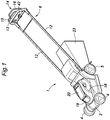
- a walk behind electric lawn mower according to an embodiment of the present invention is described in the following with reference to Figures 1 to 5 .
- the electric lawn mower 1 includes a main body 2, a work unit 3 provided in a lower part of the main body 2, a pair of front wheels 4, a pair of rear wheels 5, and a handle 6 extending rearward and upward from the main body 2.
- the work unit 3 is provided with a recess 7 that opens out downward at the center of the lower part of the main body 2 and a blade 3A that is rotatably disposed in the recess 7.
- the main body 2 is provided with an electric motor 8 having an output shaft supporting the blade 3A, and a pair of electric motors 9L and 9R connected to the left and right rear wheels 5, respectively, for rotating the rear wheels 5.
- the electric motor 8 for driving the blade 3A is referred to as a work motor 8, and the electric motors 9L and 9R for driving the rear wheels 5 are referred to as travel motors 9 in the following disclosure.
- the main body 2 is further provided with a control unit 10 for controlling these electric motors 8, 9L and 9R.
- the handle 6 includes a pair of side bars 12 extending upward and rearward from either side of the main body 2 and a cross bar grip 13 connected between the rear ends of the side bars 12.
- the cross bar grip 13 of the handle 6 is provided with an operation input unit 14 for receiving an input operation by an operator.
- the operation input unit 14 is provided with a travel lever 15 for operating the travel motors 9L and 9R and a work lever 16 for operating the work motor 8.
- the upper end of the main body 2 is provided with an upper cover 18 that covers the work motor 8, the left and right travel motors 9L and 9R, and the control unit 10.
- a battery tray 19 is formed by recessing the upper surface of the upper cover 18 to detachably receive a battery 20 for supplying electric power to the motors 8 and 9 and the control unit 10.
- the main body 2 internally defines a passage (not shown) extending from the recess 7 to the rear end of the main body 2, and a grass bag 23 is detachably fitted to an open rear end of the passage.
- the grass cut by the blade 3A is discharged from the recess 7 to the rear through the passage, and collected in the grass bag 23.
- the control unit 10 consists of an electronic control circuit (ECU) including a microcomputer, ROM, RAM, a peripheral circuit, an input / output interface, drivers and the like. As shown in Figure 3 , the control unit 10 is connected to the battery 20 and receives power supply from the battery 20.
- the control unit 10 is provided with motor drivers 31, 32 and 33 corresponding to the work motor 8 and the left and right travel motors 9L and 9R, respectively.
- the control unit 10 controls the operation of the motors 8, 9L and 9R by controlling the electric power supplied from the battery 20 to the motors 8, 9L and 9R via the motor drivers 31 to 33, for instance as a PWM control process.
- the work motor 8 and the left and right travel motors 9L and 9R are provided with respective rotational angle sensors 34, 35 and 36 for detecting the rotational angles of the corresponding motors 8, 9L and 9R.
- the rotational angle sensors 34, 35 and 36 forward signals corresponding to the rotational angles of the respective motors 8, 9L and 9R to the control unit 10, and the control unit 10 determines the rotational speeds of the motors 8, 9L and 9R according to the signals from the corresponding rotational angle sensors 34, 35 and 36.
- the control unit 10 is provided with a load detection unit 41 that detects a work motor load L [N • m] acting upon the work motor 8.
- the load detection unit 41 may detect the work motor load L based on the current (load current) flowing through the work motor 8, for instance.
- the load detection unit 41 may use the value of the current (load current value [A]) supplied to the work motor 8 as representing the work motor load L.
- the magnetostrictive torque sensor is affixed to the output shaft of the work motor 8 which is fitted with the blade 3A so that the load detection unit 41 may detect the work motor load L from the output signal of the magnetostrictive torque sensor.
- the travel lever 15 and the work lever 16 are each pivotally attached to the handle 6 so as to be moveable between an initial position where the lever 15, 16 is separated from the cross bar grip 13 of the handle 6, and an operation position where the lever 15, 16 is brought close to the cross bar grip 13 of the handle 6.
- the operation input unit 14 outputs a travel ON signal to the control unit 10 when the travel lever 15 is in the operation position, and outputs a blade ON signal to the control unit 10 when the work lever 16 is in the operation position.
- the operation input unit 14 is provided with a travel speed input unit 42 for accepting an input operation by an operator regarding the travel speed of the electric lawn mower 1.
- the travel speed input unit 42 may consist of a lever, a dial, or the like that can be displaced with respect to the main body of the operation input unit 14, and the operation input unit 14 outputs a signal corresponding to the position of the travel speed input unit 42 to the control unit 10.
- the control unit 10 Based on the signal from the operation input unit 14, the control unit 10 acquires a commanded rotational speed Vr [rpm] of the travel motors 9L and 9R corresponding to the travel speed desired by the operator.
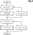
- control unit 10 awaits for a blade ON signal in step S1, and when a blade ON signal is received, the control unit 10 controls the work motor driver 31 accordingly or starts driving the work motor 8 in step S2. At this time, the control unit 10 performs a feedback control such that the rotational speed of the work motor 8 is maintained at a predetermined rotational speed VB (corresponding to the commanded rotational speed Vr selected at the travel speed input unit 42) according to the signal from the work motor rotational angle sensor 34. When no blade ON signal is received, the control unit 10 stops the work motor 8 or keeps the work motor 8 stationary in step S3. In either case, the control flow proceeds to step S4.
- VB corresponding to the commanded rotational speed Vr selected at the travel speed input unit 42
- step S4 that follows step S2 or step S3, the control unit 10 awaits for a travel ON signal.
- the control unit 10 proceeds to step S6 to stop the travel motors 9L and 9R or keep the travel motors 9L and 9R stationary.
- the control unit 10 drives the travel motors 9L and 9R in step S5.
- a drive control of the travel motors 9L and 9R is performed according to the control flow shown in Figure 5 .
- the control unit 10 firstly acquires a work motor load L [N ⁇ m] and a commanded rotational speed Vr [rpm] of the travel motors 9L and 9R in step S11.
- step S12 the control unit 10 determines if the work motor load L is equal to or greater than a first deceleration determination value L1.
- the first deceleration determination value L1 is a predetermined value indicating that the work motor load L is relatively high compared to a normal state, for instance greater than a normal load value by 10%. For example, when the normal load is 5 N • m, the first deceleration determination value L1 may be 5.5 N • m.
- step S12 determines whether the determination result in step S12 is No.
- the control unit 10 sets a target rotational speed Vt of the travel motors 9L and 9R to a commanded rotational speed Vr, and sets the target acceleration / deceleration Gt for reaching the target rotational speed Vt to a first acceleration G1 in step S21 so that the left and right travel motor drivers 32 and 33 are commanded to achieve the target rotational speed Vt at the target acceleration / deceleration Gt.
- the control unit 10 acquires the rotational speed V1 of the left and right travel motors 9L and 9R based on the output signals of the left and right travel motor rotational angle sensors 35 and 36.
- the target acceleration / deceleration Gt is set to 0, and a feedback control is performed so that the rotational speed V1 is maintained at the target rotational speed Vt.
- step S12 determines if the work motor load L is equal to or greater than a second deceleration determination value L2 in step S13.
- the second deceleration determination value L2 is greater than the first deceleration determination value L1.
- the first deceleration determination value L1 is set to 5.5 N • m
- the second deceleration determination value L2 may be set to 6.5 N • m.
- the control unit 10 then controls the left and right travel motor drivers 32 and 33 so as to reach the target rotational speed Vt at the first deceleration G2.
- the process in step 14 is named as "first deceleration control".
- the control unit 10 determines if the work motor load L is equal to or greater than a stop determination value L3 in step S15.
- the stop determination value L3 is set to a value greater than the second deceleration determination value L2. For example, when the second deceleration determination value L2 is set to 6.5 N • m, the stop determination value L3 may be set to 7.5 N ⁇ m.
- the second deceleration G3 is set to a value greater than the first deceleration G2 in value in the deceleration direction.
- the first deceleration G2 may be 200 rpm/s
- the second deceleration G3 may be 250 rpm/s.
- the process in step S16 is named as "second deceleration control".
- step S15 determines whether the travel motors 9L and 9R are moving or not.
- the control unit 10 controls the left and right travel motor drivers 32 and 33 so as to bring the travel motors 9L and 9R to come to a stop in step S17.
- the deceleration of the travel motors 9L and 9R in coming to a stop is preferably sufficiently greater than the second deceleration G3.
- the process in step S17 is named as "stop control".
- control unit 10 After performing the processing of any one of steps S14, S16 and S17, the control unit 10 again acquires the work motor load L in Step S18.
- step S19 the control unit 10 determines if the work motor load L is equal to or less than a return determination value L4 in step S18.
- the return determination value L4 is selected as a value smaller than the first deceleration determination value L1. For example, when the first deceleration determination value L1 is set to 5.5 N ⁇ m, the return determination value L4 may be set to 5.0 N ⁇ m.
- step S19 the control flow returns to step S13 to repeat the processing of steps S13 to S16 until the determination result in step S19 becomes Yes. If the determination result in step S19 is Yes, in step S20, the target rotational speed Vt of the travel motors 9L and 9R is set to the commanded rotational speed Vr, and the target acceleration / deceleration Gt for reaching the target rotational speed Vt is set to the second acceleration G4 so that the left and right travel motor drivers 32 and 33 are commanded to achieve the target rotational speed Vt at the target acceleration / deceleration Gt.
- the control unit 10 acquires the rotational speed V1 of the left and right travel motors 9L and 9R according the signals from the left and right travel motor rotational angle sensors 35 and 36.
- the target acceleration / deceleration Gt is set to zero, and a feedback control is performed so that the rotational speed V1 is maintained at the target rotational speed Vt .
- the second acceleration G4 is set to a value greater in value than the first acceleration G1.
- the first acceleration G1 may be 100 rpm/s
- the second acceleration G4 may be 150 rpm/s.
- the process in step S20 may be called as "return control".
- the electric lawn mower 1 operates as discussed in the following.
- the work lever 16 is turned on by pressing the work lever 16 against the cross bar grip 13
- the work motor 8 is driven, and the blade 3A rotates at a rotational speed VB so that lawn mowing can be performed.
- the travel lever 15 is turned on in addition to the work lever 16, the travel motors 9L and 9R start driving the rear wheels 5 so that the electric lawn mower 1 travels forward at a certain speed. In the illustrated embodiment, when the electric lawn mower 1 travels forward, the blade 3A necessarily rotates.
- the mode of operation of the electric lawn mower 1 passing through heavy work areas where a large amount of grass has to be cut is discussed in the following.
- the electric lawn mower 1 passes through a heavy work area from time T2 to T4, and from time T7 to T11.
- the travel lever 15 and the work lever 16 of the electric lawn mower 1 are turned on.
- the control unit 10 drives the work motor 8 at a constant rotational speed VB, and drives the left and right travel motors 9L and 9R with a commanded rotational speed Vr set as a target rotational speed Vt and the acceleration G of the left and right travel motors 9L and 9R set to the first acceleration G1.
- the rotational speed V1 of the travel motors 9L and 9R reaches the commanded rotational speed Vr at time T1, and the control unit 10 thereafter maintains the rotational speed V1 of the travel motors 9L and 9R at the commanded rotational speed Vr while maintaining a zero acceleration G for the travel motors 9L and 9R.
- the control unit 10 performs the first deceleration control by driving the travel motors 9L and 9R with the target rotational speed Vt set to zero and the acceleration / deceleration G of the travel motors 9L and 9R set to the first deceleration G2.
- the rotational speed of the left and right travel motors 9L and 9R and the travel speed of the electric lawn mower 1 are reduced so that the amount of grass that is to be cut by the blade 3A in a unit time decreases, and the work motor load L decreases. Once the electric lawn mower 1 leaves the heavy work area at time T4, the work motor load L is further reduced.
- the control unit 10 When the work motor load L becomes equal to or less than the return determination value L4 at time T5, the control unit 10 performs the return control, and commands the travel motors 9L and 9R to operate with the target rotational speed Vt set to the commanded rotational speed Vr and the acceleration / deceleration G set to the second acceleration G4 so that the rotational speed of the travel motors 9L and 9R is restored to the rotational speed prior to entering the heavy load area.
- the rotational speed of the left and right travel motors 9L and 9R and hence the travel speed of the electric lawn mower 1 increase, and the work motor load L increases.
- the control unit 10 maintains the rotational speed V1 at the commanded rotational speed Vr, and sets the acceleration / deceleration G to zero.
- the work motor load L sharply increases.
- the control unit 10 performs the first deceleration control by commanding the travel motors 9L and 9R to operate with the target rotational speed Vt set to zero and the acceleration / deceleration G set to the first deceleration G2.
- the rotational speed of the left and right travel motors 9L and 9R and hence the travel speed of the electric lawn mower 1 are decreased, and the increase rate of the work motor load L is reduced.
- the control unit 10 performs the second deceleration control by commanding the left and right travel motors 9L and 9R to operate with the target rotational speed Vt set to zero and the acceleration / deceleration G set to the second deceleration G3.
- the left and right travel motors 9L are 9R are further decelerated.
- the control unit 10 performs the stop control by stopping the left and right travel motors 9L and 9R altogether.
- the electric lawn mower 1 stops traveling, but continues to rotate the blade 3A at the same spot to continue cutting the grass. This causes the work motor load L to rapidly decrease.
- the control unit 10 When the work motor load L becomes equal to or lower than the restoration determination value L4 at time T11, the control unit 10 performs the restoration control by commanding the left and right travel motors 9L and 9R to operate with the target rotational speed Vt set to the commanded rotational speed Vr and the acceleration / deceleration G set to the second acceleration G4. As a result, the rotational speed of the left and right travel motors 9L and 9R and hence the travel speed of the electric lawn mower 1 increase, and the work motor load L increases.
- the control unit 10 After the rotational speed V1 of the travel motors 9L and 9R has reached the commanded rotational speed Vr at time T12, the control unit 10 maintains the acceleration / deceleration G at zero and maintains the rotational speed V1 at the commanded rotational speed Vr.
- the rotational speed of the travel motors 9L and 9R that corresponds to the travel speed of the electric lawn mower 1 is determined according to the commanded rotational speed Vr which is selected by the operator, and the work motor load L.
- the travel motors 9L and 9R are operated so that the rotational speed thereof is equal to the commanded rotational speed Vr.
- the travel motors 9L and 9R are operated so that the rotational speed thereof is lower than the commanded rotational speed Vr.
- control unit 10 is provided with the first deceleration determination value L1 for determining the timing at which deceleration of the travel motors 9L and 9R is initiated and the return determination value L4 for determining the timing for ceasing the deceleration so that the deceleration is continued from the time at which the work motor load L has become equal to or greater than the deceleration determination value L1 until the time at which the work motor load L has become equal to or less than the return determination value L4, hunting in the control action is prevented from occurring.
- control unit 10 changes the rotational speed of the work motors 9L and 9R when the work motor load L has exceeded or fallen below prescribed values such as the first deceleration determination value L1, the second deceleration determination value L2 and the return determination value L4 at the corresponding rates (acceleration/deceleration), sudden deceleration and acceleration of the electric lawn mower 1 can be avoided, and the operator is enabled to operate the electric lawn mower 1 in a comfortable manner.
- the rotational speed of the work motors 9L and 9R can be reduced whenever appropriate in a prompt manner.
- control unit 10 completely stops the travel motors 9L and 9R when the work motor load L becomes equal to or greater than the stop determination value L3 which is selected as a value greater than the second deceleration determination value L2 so that the work motor load L can be reduced particularly promptly.
- the electric lawn mower 1 was provided with a pair of rear wheels 5 that are individually driven by the right and left travel motors 9R and 9L, but may also be provided with a single travel motor for driving both of the rear wheels 5.
- the present invention can be applied not only to lawn mowers but also to grass trimmers, snow blowers, tillers and other kinds of electric power equipment fitted with a power propulsion device.
- the work unit may include an auger for snow removal.
- the work unit may comprise a rotary tiller blade.
- the control unit 10 may preferably perform a low rotational speed operation control to increase the rotational speed of the travel motors 9L and 9R to a prescribed low rotational speed VL that is lower than the rotational speed thereof prior to the deceleration control (i.e., the commanded rotational speed Vr).
- a low rotational speed operation control to increase the rotational speed of the travel motors 9L and 9R to a prescribed low rotational speed VL that is lower than the rotational speed thereof prior to the deceleration control (i.e., the commanded rotational speed Vr).
- the rotational speed of the travel motors 9L and 9R was changed according to the work motor load L detected by the load detection unit 41 as a current flowing through the work motor 8 or as an output signal from the magnetostrictive torque sensor.
- the work motor load L may be represented by the rotational speed of the work motor 8 in such a high load condition that the rotational speed of the work motor 8 cannot be maintained at a constant value but is decreased in accordance with an increase in the work motor load.
- the various determination values may be defined in terms of the rotational speed of the work motor.
Landscapes
- Life Sciences & Earth Sciences (AREA)
- Environmental Sciences (AREA)
- Engineering & Computer Science (AREA)
- Sustainable Development (AREA)
- Sustainable Energy (AREA)
- Power Engineering (AREA)
- Transportation (AREA)
- Mechanical Engineering (AREA)
- Harvester Elements (AREA)
- Control Of Multiple Motors (AREA)
- Electric Propulsion And Braking For Vehicles (AREA)
Claims (6)
- Elektrische Leistungsausrüstung (1), umfassend:eine Arbeitseinheit (3) zum Durchführen einer vorgeschriebenen Arbeit;einen Arbeitsmotor (8) zum Antreiben der Arbeitseinheit;eine Fahrt-Einheit (5) zum Ermöglichen der elektrischen Leistungsausrüstung, auf einer Bodenfläche zu fahren;einen Fahrt-Motor (9) zum Antreiben der Fahrt-Einheit; undeine Steuereinheit (10) um Steuern eines Betriebs des Arbeitsmotors und des Fahrt-Motors, wobei die Steuereinheit dazu eingerichtet ist, eine Rotationsgeschwindigkeit des Arbeitsmotors bei einem konstanten Wert zu halten;wobei die Steuereinheit ferner dazu eingerichtet ist, eine Rotationsgeschwindigkeit des Fahrt-Motors in Reaktion auf einen Anstieg in einer Last abzusenken, welche auf den Arbeitsmotor ausgeübt wird, und wobei die elektrische Leistungsausrüstung ferner eine Last-Detektionseinheit (41) zum Detektieren einer Last umfasst, welche auf den Arbeitsmotor wirkt,dadurch gekennzeichnet, dassdie Steuereinheit dazu eingerichtet ist, eine Verzögerung-Steuerung durchzuführen, wodurch die Rotationsgeschwindigkeit des Fahrt-Motors bei einer vorgeschriebenen Verzögerung verzögert wird, wenn die detektierte Last größer oder gleich ist als ein Verzögerung-Bestimmungswert, und wenn die Last kleiner oder gleich wird als ein Rückkehr-Bestimmungswert, welcher kleiner oder gleich ist wie der Verzögerung-Bestimmungswert während der Verzögerung-Steuerung, eine Rückkehr-Steuerung durchzuführen, wodurch die Rotationsgeschwindigkeit des Fahrt-Motors auf einen Wert davon vor der vorangehenden Verzögerung-Steuerung durch Beschleunigen des Fahrt-Motors bei einer vorgeschriebenen Beschleunigung zurückgeführt wird.
- Elektrische Leistungsausrüstung nach Anspruch 1, wobei die Steuereinheit derart eingerichtet ist, dass, wenn die Last größer oder gleich einem Stopp-Bestimmungswert wird, welcher größer ist als der Verzögerung-Bestimmungswert während der Verzögerung-Steuerung, die Steuereinheit eine Stopp-Steuerung durchführt, um den Fahrt-Motor zu stoppen, und wenn die Last kleiner oder gleich dem Rückkehr-Bestimmungswert während der Stopp-Steuerung wird, führt die Steuereinheit die Rückkehr-Steuerung durch, wodurch die Rotationsgeschwindigkeit des Fahrt-Motors zu dem Wert davon vor der vorhergehenden Verzögerung-Steuerung durch Beschleunigen des Fahrt-Motors bei der vorgeschriebenen Beschleunigung durchgeführt wird.
- Elektrische Leistungsausrüstung nach Anspruch 2, wobei die Steuereinheit derart eingerichtet ist, dass, wenn die Last kleiner oder gleich einem zweiten Rückkehr-Bestimmungswert wird, welcher größer als der Rückkehr-Bestimmungswert und kleiner als der Stopp-Bestimmungswert während der Stopp-Steuerung ist, führt die Steuereinheit eine Steuerung eines Betriebs mit geringer Rotationsgeschwindigkeit durch, wodurch die Rotationsgeschwindigkeit des Fahrt-Motors auf eine vorgeschriebene geringe Rotationsgeschwindigkeit gesteigert wird, welche geringer ist als die Rotationsgeschwindigkeit davon vor der Verzögerung-Steuerung.
- Elektrische Leistungsausrüstung nach einem der Ansprüche 1 bis 3, wobei der Verzögerung-Bestimmungswert eine Mehrzahl von Verzögerung-Bestimmungswerten umfasst und die Verzögerung-Steuerung durchgeführt wird, so dass die vorgeschriebene Verzögerung mit einer Steigerung in dem Verzögerung-Bestimmungswert gesteigert wird.
- Elektrische Leistungsausrüstung nach einem der Ansprüche 1 bis 4, wobei die Arbeitseinheit eine Rotorschaufel (3A) umfasst, welche durch den Arbeitsmotor angetrieben wird und einen Teil eines Rasenmähers bildet.
- Elektrische Leistungsausrüstung nach einem der Ansprüche 1 bis 5, wobei Steuereinheit dazu eingerichtet ist, die Rotationsgeschwindigkeit des Fahrt-Motors in Reaktion auf eine Absenkung in der Last zu steigern, welche auf den Arbeitsmotor ausgeübt wird.
Applications Claiming Priority (1)
| Application Number | Priority Date | Filing Date | Title |
|---|---|---|---|
| JP2016229547A JP6672128B2 (ja) | 2016-11-25 | 2016-11-25 | 作業機 |
Publications (2)
| Publication Number | Publication Date |
|---|---|
| EP3326443A1 EP3326443A1 (de) | 2018-05-30 |
| EP3326443B1 true EP3326443B1 (de) | 2020-05-20 |
Family
ID=60450520
Family Applications (1)
| Application Number | Title | Priority Date | Filing Date |
|---|---|---|---|
| EP17203143.7A Active EP3326443B1 (de) | 2016-11-25 | 2017-11-22 | Elektrische anlage |
Country Status (3)
| Country | Link |
|---|---|
| US (1) | US10709061B2 (de) |
| EP (1) | EP3326443B1 (de) |
| JP (1) | JP6672128B2 (de) |
Families Citing this family (17)
| Publication number | Priority date | Publication date | Assignee | Title |
|---|---|---|---|---|
| WO2019097683A1 (ja) * | 2017-11-17 | 2019-05-23 | 本田技研工業株式会社 | 作業機 |
| JP7038536B2 (ja) * | 2017-12-12 | 2022-03-18 | 株式会社クボタ | 作業車両 |
| JP6982167B2 (ja) * | 2018-03-09 | 2021-12-17 | 本田技研工業株式会社 | 作業機 |
| EP3586594B1 (de) * | 2018-06-29 | 2022-10-19 | Techtronic Outdoor Products Technology Limited | Handgeführtes, elektrisches gartengerät |
| AU2018437976B2 (en) * | 2018-08-24 | 2023-02-09 | Honda Motor Co., Ltd. | Work machine |
| CN110946000B (zh) | 2018-09-27 | 2022-03-01 | 南京德朔实业有限公司 | 割草机 |
| EP3821692B1 (de) | 2018-09-27 | 2024-07-31 | Nanjing Chervon Industry Co., Ltd. | Rasenmäher |
| DE102019213294A1 (de) * | 2019-02-28 | 2020-09-03 | Robert Bosch Gmbh | Angetriebene Bodenpflegevorrichtung |
| USD995569S1 (en) | 2019-04-18 | 2023-08-15 | Nanjing Chervon Industry Co., Ltd. | Mower blade assembly |
| JP7022409B2 (ja) * | 2019-06-21 | 2022-02-18 | 株式会社ササキコーポレーション | 自走式作業機の制御方法及び制御装置 |
| CN113273078A (zh) | 2019-06-21 | 2021-08-17 | 南京德朔实业有限公司 | 骑乘式割草机 |
| JP7250289B2 (ja) * | 2020-11-11 | 2023-04-03 | 株式会社ユニック | 草刈り機 |
| CN216567136U (zh) | 2021-10-15 | 2022-05-24 | 创科无线普通合伙 | 一种割草机 |
| JP7675434B2 (ja) * | 2021-10-22 | 2025-05-13 | 株式会社 神崎高級工機製作所 | 電動作業車両 |
| US12576724B2 (en) | 2021-11-30 | 2026-03-17 | Honda Motor Co., Ltd. | Electric power equipment |
| US20240117596A1 (en) | 2022-10-10 | 2024-04-11 | Great Plains Manufacturing, Inc. | Work machine system for monitoring auxiliary pressures |
| US20250065871A1 (en) * | 2023-08-21 | 2025-02-27 | Kubota Corporation | Work machine |
Family Cites Families (12)
| Publication number | Priority date | Publication date | Assignee | Title |
|---|---|---|---|---|
| JP3280047B2 (ja) * | 1991-07-03 | 2002-04-30 | 株式会社クボタ | コンバイン |
| JPH09201126A (ja) | 1995-11-24 | 1997-08-05 | Honda Motor Co Ltd | 電動芝刈機 |
| JP3798846B2 (ja) * | 1996-04-30 | 2006-07-19 | ヤンマー農機株式会社 | コンバインの車速制御装置 |
| JP4279275B2 (ja) * | 2005-07-29 | 2009-06-17 | 本田技研工業株式会社 | 作業機 |
| US7594377B1 (en) | 2006-10-27 | 2009-09-29 | Sauer-Danfoss Inc. | Means of adjusting ground speed of a vehicle based on load on blade assembly |
| US20090266042A1 (en) | 2008-04-25 | 2009-10-29 | Mooney P Wade | Mower |
| JP2009296933A (ja) | 2008-06-12 | 2009-12-24 | Honda Motor Co Ltd | 耕耘機 |
| JP5576152B2 (ja) * | 2010-03-12 | 2014-08-20 | ヤンマー株式会社 | 作業車 |
| JP5715855B2 (ja) * | 2011-03-09 | 2015-05-13 | 株式会社クボタ | 乗用作業車 |
| EP2731413B1 (de) * | 2011-07-14 | 2017-10-04 | Husqvarna AB | Batteriebetriebenes rasenpflegefahrzeug mit motoreffizienzanzeige |
| US10130037B2 (en) * | 2014-12-31 | 2018-11-20 | Mean Green Products, LLC | Electric mower apparatus and method of use |
| JP6023239B2 (ja) | 2015-02-25 | 2016-11-09 | 本田技研工業株式会社 | 除雪機 |
-
2016
- 2016-11-25 JP JP2016229547A patent/JP6672128B2/ja not_active Expired - Fee Related
-
2017
- 2017-11-17 US US15/815,994 patent/US10709061B2/en not_active Expired - Fee Related
- 2017-11-22 EP EP17203143.7A patent/EP3326443B1/de active Active
Non-Patent Citations (1)
| Title |
|---|
| None * |
Also Published As
| Publication number | Publication date |
|---|---|
| JP2018085907A (ja) | 2018-05-31 |
| US20180146616A1 (en) | 2018-05-31 |
| US10709061B2 (en) | 2020-07-14 |
| EP3326443A1 (de) | 2018-05-30 |
| JP6672128B2 (ja) | 2020-03-25 |
Similar Documents
| Publication | Publication Date | Title |
|---|---|---|
| EP3326443B1 (de) | Elektrische anlage | |
| EP3326444B1 (de) | Elektrisches gerät | |
| EP3545746B1 (de) | Arbeitsmaschine | |
| JP6815276B2 (ja) | 草刈機 | |
| EP3545744B1 (de) | Arbeitsmaschine | |
| EP3501947B1 (de) | Elektrisch betriebenes arbeitsfahrzeug | |
| US11026366B2 (en) | Power equipment | |
| JP2023004671A (ja) | 乗用型草刈機 | |
| EP1716737B1 (de) | Vierradgetriebener Mähdrescher mit Schlupfregelung | |
| JP5580783B2 (ja) | 作業車 | |
| CN104969713A (zh) | 工具机、尤其是割草机,用于运行的方法 | |
| JP6395670B2 (ja) | 乗用作業車 | |
| JP6243124B2 (ja) | 除雪機 | |
| JP7269036B2 (ja) | 走行車両 | |
| US20230166603A1 (en) | Electric power equipment | |
| JP4795563B2 (ja) | 移動農機の作業部補助出力装置 | |
| JP7675434B2 (ja) | 電動作業車両 | |
| US20250318460A1 (en) | Electric mowing vehicle | |
| JP3050823B2 (ja) | 走行車両における操向制御装置 | |
| JPH0595722A (ja) | コンバインの車速制御装置 |
Legal Events
| Date | Code | Title | Description |
|---|---|---|---|
| PUAI | Public reference made under article 153(3) epc to a published international application that has entered the european phase |
Free format text: ORIGINAL CODE: 0009012 |
|
| STAA | Information on the status of an ep patent application or granted ep patent |
Free format text: STATUS: REQUEST FOR EXAMINATION WAS MADE |
|
| 17P | Request for examination filed |
Effective date: 20171122 |
|
| AK | Designated contracting states |
Kind code of ref document: A1 Designated state(s): AL AT BE BG CH CY CZ DE DK EE ES FI FR GB GR HR HU IE IS IT LI LT LU LV MC MK MT NL NO PL PT RO RS SE SI SK SM TR |
|
| AX | Request for extension of the european patent |
Extension state: BA ME |
|
| GRAP | Despatch of communication of intention to grant a patent |
Free format text: ORIGINAL CODE: EPIDOSNIGR1 |
|
| STAA | Information on the status of an ep patent application or granted ep patent |
Free format text: STATUS: GRANT OF PATENT IS INTENDED |
|
| INTG | Intention to grant announced |
Effective date: 20200108 |
|
| GRAS | Grant fee paid |
Free format text: ORIGINAL CODE: EPIDOSNIGR3 |
|
| GRAA | (expected) grant |
Free format text: ORIGINAL CODE: 0009210 |
|
| STAA | Information on the status of an ep patent application or granted ep patent |
Free format text: STATUS: THE PATENT HAS BEEN GRANTED |
|
| AK | Designated contracting states |
Kind code of ref document: B1 Designated state(s): AL AT BE BG CH CY CZ DE DK EE ES FI FR GB GR HR HU IE IS IT LI LT LU LV MC MK MT NL NO PL PT RO RS SE SI SK SM TR |
|
| REG | Reference to a national code |
Ref country code: GB Ref legal event code: FG4D |
|
| REG | Reference to a national code |
Ref country code: CH Ref legal event code: EP |
|
| REG | Reference to a national code |
Ref country code: DE Ref legal event code: R096 Ref document number: 602017016983 Country of ref document: DE |
|
| REG | Reference to a national code |
Ref country code: AT Ref legal event code: REF Ref document number: 1271980 Country of ref document: AT Kind code of ref document: T Effective date: 20200615 |
|
| REG | Reference to a national code |
Ref country code: LT Ref legal event code: MG4D |
|
| REG | Reference to a national code |
Ref country code: NL Ref legal event code: MP Effective date: 20200520 |
|
| PG25 | Lapsed in a contracting state [announced via postgrant information from national office to epo] |
Ref country code: LT Free format text: LAPSE BECAUSE OF FAILURE TO SUBMIT A TRANSLATION OF THE DESCRIPTION OR TO PAY THE FEE WITHIN THE PRESCRIBED TIME-LIMIT Effective date: 20200520 Ref country code: GR Free format text: LAPSE BECAUSE OF FAILURE TO SUBMIT A TRANSLATION OF THE DESCRIPTION OR TO PAY THE FEE WITHIN THE PRESCRIBED TIME-LIMIT Effective date: 20200821 Ref country code: NO Free format text: LAPSE BECAUSE OF FAILURE TO SUBMIT A TRANSLATION OF THE DESCRIPTION OR TO PAY THE FEE WITHIN THE PRESCRIBED TIME-LIMIT Effective date: 20200820 Ref country code: SE Free format text: LAPSE BECAUSE OF FAILURE TO SUBMIT A TRANSLATION OF THE DESCRIPTION OR TO PAY THE FEE WITHIN THE PRESCRIBED TIME-LIMIT Effective date: 20200520 Ref country code: PT Free format text: LAPSE BECAUSE OF FAILURE TO SUBMIT A TRANSLATION OF THE DESCRIPTION OR TO PAY THE FEE WITHIN THE PRESCRIBED TIME-LIMIT Effective date: 20200921 Ref country code: FI Free format text: LAPSE BECAUSE OF FAILURE TO SUBMIT A TRANSLATION OF THE DESCRIPTION OR TO PAY THE FEE WITHIN THE PRESCRIBED TIME-LIMIT Effective date: 20200520 Ref country code: IS Free format text: LAPSE BECAUSE OF FAILURE TO SUBMIT A TRANSLATION OF THE DESCRIPTION OR TO PAY THE FEE WITHIN THE PRESCRIBED TIME-LIMIT Effective date: 20200920 |
|
| PG25 | Lapsed in a contracting state [announced via postgrant information from national office to epo] |
Ref country code: RS Free format text: LAPSE BECAUSE OF FAILURE TO SUBMIT A TRANSLATION OF THE DESCRIPTION OR TO PAY THE FEE WITHIN THE PRESCRIBED TIME-LIMIT Effective date: 20200520 Ref country code: HR Free format text: LAPSE BECAUSE OF FAILURE TO SUBMIT A TRANSLATION OF THE DESCRIPTION OR TO PAY THE FEE WITHIN THE PRESCRIBED TIME-LIMIT Effective date: 20200520 Ref country code: LV Free format text: LAPSE BECAUSE OF FAILURE TO SUBMIT A TRANSLATION OF THE DESCRIPTION OR TO PAY THE FEE WITHIN THE PRESCRIBED TIME-LIMIT Effective date: 20200520 Ref country code: BG Free format text: LAPSE BECAUSE OF FAILURE TO SUBMIT A TRANSLATION OF THE DESCRIPTION OR TO PAY THE FEE WITHIN THE PRESCRIBED TIME-LIMIT Effective date: 20200820 |
|
| REG | Reference to a national code |
Ref country code: AT Ref legal event code: MK05 Ref document number: 1271980 Country of ref document: AT Kind code of ref document: T Effective date: 20200520 |
|
| PG25 | Lapsed in a contracting state [announced via postgrant information from national office to epo] |
Ref country code: NL Free format text: LAPSE BECAUSE OF FAILURE TO SUBMIT A TRANSLATION OF THE DESCRIPTION OR TO PAY THE FEE WITHIN THE PRESCRIBED TIME-LIMIT Effective date: 20200520 Ref country code: AL Free format text: LAPSE BECAUSE OF FAILURE TO SUBMIT A TRANSLATION OF THE DESCRIPTION OR TO PAY THE FEE WITHIN THE PRESCRIBED TIME-LIMIT Effective date: 20200520 |
|
| PG25 | Lapsed in a contracting state [announced via postgrant information from national office to epo] |
Ref country code: CZ Free format text: LAPSE BECAUSE OF FAILURE TO SUBMIT A TRANSLATION OF THE DESCRIPTION OR TO PAY THE FEE WITHIN THE PRESCRIBED TIME-LIMIT Effective date: 20200520 Ref country code: RO Free format text: LAPSE BECAUSE OF FAILURE TO SUBMIT A TRANSLATION OF THE DESCRIPTION OR TO PAY THE FEE WITHIN THE PRESCRIBED TIME-LIMIT Effective date: 20200520 Ref country code: AT Free format text: LAPSE BECAUSE OF FAILURE TO SUBMIT A TRANSLATION OF THE DESCRIPTION OR TO PAY THE FEE WITHIN THE PRESCRIBED TIME-LIMIT Effective date: 20200520 Ref country code: DK Free format text: LAPSE BECAUSE OF FAILURE TO SUBMIT A TRANSLATION OF THE DESCRIPTION OR TO PAY THE FEE WITHIN THE PRESCRIBED TIME-LIMIT Effective date: 20200520 Ref country code: IT Free format text: LAPSE BECAUSE OF FAILURE TO SUBMIT A TRANSLATION OF THE DESCRIPTION OR TO PAY THE FEE WITHIN THE PRESCRIBED TIME-LIMIT Effective date: 20200520 Ref country code: EE Free format text: LAPSE BECAUSE OF FAILURE TO SUBMIT A TRANSLATION OF THE DESCRIPTION OR TO PAY THE FEE WITHIN THE PRESCRIBED TIME-LIMIT Effective date: 20200520 Ref country code: SM Free format text: LAPSE BECAUSE OF FAILURE TO SUBMIT A TRANSLATION OF THE DESCRIPTION OR TO PAY THE FEE WITHIN THE PRESCRIBED TIME-LIMIT Effective date: 20200520 Ref country code: ES Free format text: LAPSE BECAUSE OF FAILURE TO SUBMIT A TRANSLATION OF THE DESCRIPTION OR TO PAY THE FEE WITHIN THE PRESCRIBED TIME-LIMIT Effective date: 20200520 |
|
| REG | Reference to a national code |
Ref country code: DE Ref legal event code: R097 Ref document number: 602017016983 Country of ref document: DE |
|
| PG25 | Lapsed in a contracting state [announced via postgrant information from national office to epo] |
Ref country code: SK Free format text: LAPSE BECAUSE OF FAILURE TO SUBMIT A TRANSLATION OF THE DESCRIPTION OR TO PAY THE FEE WITHIN THE PRESCRIBED TIME-LIMIT Effective date: 20200520 Ref country code: PL Free format text: LAPSE BECAUSE OF FAILURE TO SUBMIT A TRANSLATION OF THE DESCRIPTION OR TO PAY THE FEE WITHIN THE PRESCRIBED TIME-LIMIT Effective date: 20200520 |
|
| PLBE | No opposition filed within time limit |
Free format text: ORIGINAL CODE: 0009261 |
|
| STAA | Information on the status of an ep patent application or granted ep patent |
Free format text: STATUS: NO OPPOSITION FILED WITHIN TIME LIMIT |
|
| 26N | No opposition filed |
Effective date: 20210223 |
|
| PG25 | Lapsed in a contracting state [announced via postgrant information from national office to epo] |
Ref country code: SI Free format text: LAPSE BECAUSE OF FAILURE TO SUBMIT A TRANSLATION OF THE DESCRIPTION OR TO PAY THE FEE WITHIN THE PRESCRIBED TIME-LIMIT Effective date: 20200520 |
|
| PG25 | Lapsed in a contracting state [announced via postgrant information from national office to epo] |
Ref country code: MC Free format text: LAPSE BECAUSE OF FAILURE TO SUBMIT A TRANSLATION OF THE DESCRIPTION OR TO PAY THE FEE WITHIN THE PRESCRIBED TIME-LIMIT Effective date: 20200520 |
|
| REG | Reference to a national code |
Ref country code: CH Ref legal event code: PL |
|
| PG25 | Lapsed in a contracting state [announced via postgrant information from national office to epo] |
Ref country code: LU Free format text: LAPSE BECAUSE OF NON-PAYMENT OF DUE FEES Effective date: 20201122 |
|
| REG | Reference to a national code |
Ref country code: BE Ref legal event code: MM Effective date: 20201130 |
|
| PG25 | Lapsed in a contracting state [announced via postgrant information from national office to epo] |
Ref country code: CH Free format text: LAPSE BECAUSE OF NON-PAYMENT OF DUE FEES Effective date: 20201130 Ref country code: LI Free format text: LAPSE BECAUSE OF NON-PAYMENT OF DUE FEES Effective date: 20201130 |
|
| PG25 | Lapsed in a contracting state [announced via postgrant information from national office to epo] |
Ref country code: IE Free format text: LAPSE BECAUSE OF NON-PAYMENT OF DUE FEES Effective date: 20201122 |
|
| PG25 | Lapsed in a contracting state [announced via postgrant information from national office to epo] |
Ref country code: TR Free format text: LAPSE BECAUSE OF FAILURE TO SUBMIT A TRANSLATION OF THE DESCRIPTION OR TO PAY THE FEE WITHIN THE PRESCRIBED TIME-LIMIT Effective date: 20200520 Ref country code: MT Free format text: LAPSE BECAUSE OF FAILURE TO SUBMIT A TRANSLATION OF THE DESCRIPTION OR TO PAY THE FEE WITHIN THE PRESCRIBED TIME-LIMIT Effective date: 20200520 Ref country code: CY Free format text: LAPSE BECAUSE OF FAILURE TO SUBMIT A TRANSLATION OF THE DESCRIPTION OR TO PAY THE FEE WITHIN THE PRESCRIBED TIME-LIMIT Effective date: 20200520 |
|
| PG25 | Lapsed in a contracting state [announced via postgrant information from national office to epo] |
Ref country code: MK Free format text: LAPSE BECAUSE OF FAILURE TO SUBMIT A TRANSLATION OF THE DESCRIPTION OR TO PAY THE FEE WITHIN THE PRESCRIBED TIME-LIMIT Effective date: 20200520 |
|
| GBPC | Gb: european patent ceased through non-payment of renewal fee |
Effective date: 20211122 |
|
| PG25 | Lapsed in a contracting state [announced via postgrant information from national office to epo] |
Ref country code: BE Free format text: LAPSE BECAUSE OF NON-PAYMENT OF DUE FEES Effective date: 20201130 |
|
| PG25 | Lapsed in a contracting state [announced via postgrant information from national office to epo] |
Ref country code: GB Free format text: LAPSE BECAUSE OF NON-PAYMENT OF DUE FEES Effective date: 20211122 |
|
| REG | Reference to a national code |
Ref country code: DE Ref legal event code: R084 Ref document number: 602017016983 Country of ref document: DE |
|
| PGFP | Annual fee paid to national office [announced via postgrant information from national office to epo] |
Ref country code: FR Payment date: 20230929 Year of fee payment: 7 |
|
| PGFP | Annual fee paid to national office [announced via postgrant information from national office to epo] |
Ref country code: DE Payment date: 20230926 Year of fee payment: 7 |
|
| REG | Reference to a national code |
Ref country code: DE Ref legal event code: R119 Ref document number: 602017016983 Country of ref document: DE |
|
| PG25 | Lapsed in a contracting state [announced via postgrant information from national office to epo] |
Ref country code: DE Free format text: LAPSE BECAUSE OF NON-PAYMENT OF DUE FEES Effective date: 20250603 |
|
| PG25 | Lapsed in a contracting state [announced via postgrant information from national office to epo] |
Ref country code: FR Free format text: LAPSE BECAUSE OF NON-PAYMENT OF DUE FEES Effective date: 20241130 |