EP3326451B1 - Ballenpresse für loses pressgut - Google Patents
Ballenpresse für loses pressgut Download PDFInfo
- Publication number
- EP3326451B1 EP3326451B1 EP17199144.1A EP17199144A EP3326451B1 EP 3326451 B1 EP3326451 B1 EP 3326451B1 EP 17199144 A EP17199144 A EP 17199144A EP 3326451 B1 EP3326451 B1 EP 3326451B1
- Authority
- EP
- European Patent Office
- Prior art keywords
- bale
- pressing
- strapping
- channel
- discharge
- Prior art date
- Legal status (The legal status is an assumption and is not a legal conclusion. Google has not performed a legal analysis and makes no representation as to the accuracy of the status listed.)
- Active
Links
Images




Classifications
-
- A—HUMAN NECESSITIES
- A01—AGRICULTURE; FORESTRY; ANIMAL HUSBANDRY; HUNTING; TRAPPING; FISHING
- A01F—PROCESSING OF HARVESTED PRODUCE; HAY OR STRAW PRESSES; DEVICES FOR STORING AGRICULTURAL OR HORTICULTURAL PRODUCE
- A01F15/00—Baling presses for straw, hay or the like
- A01F15/08—Details
- A01F15/14—Tying devices specially adapted for baling presses
-
- B—PERFORMING OPERATIONS; TRANSPORTING
- B30—PRESSES
- B30B—PRESSES IN GENERAL
- B30B9/00—Presses specially adapted for particular purposes
- B30B9/30—Presses specially adapted for particular purposes for baling; Compression boxes therefor
- B30B9/3003—Details
-
- B—PERFORMING OPERATIONS; TRANSPORTING
- B30—PRESSES
- B30B—PRESSES IN GENERAL
- B30B9/00—Presses specially adapted for particular purposes
- B30B9/30—Presses specially adapted for particular purposes for baling; Compression boxes therefor
- B30B9/3003—Details
- B30B9/3014—Ejection means
-
- B—PERFORMING OPERATIONS; TRANSPORTING
- B30—PRESSES
- B30B—PRESSES IN GENERAL
- B30B9/00—Presses specially adapted for particular purposes
- B30B9/30—Presses specially adapted for particular purposes for baling; Compression boxes therefor
- B30B9/3078—Presses specially adapted for particular purposes for baling; Compression boxes therefor with precompression means
-
- B—PERFORMING OPERATIONS; TRANSPORTING
- B30—PRESSES
- B30B—PRESSES IN GENERAL
- B30B9/00—Presses specially adapted for particular purposes
- B30B9/30—Presses specially adapted for particular purposes for baling; Compression boxes therefor
- B30B9/3096—Presses specially adapted for particular purposes for baling; Compression boxes therefor the means against which, or wherein, the material is compacted being retractable
-
- B—PERFORMING OPERATIONS; TRANSPORTING
- B65—CONVEYING; PACKING; STORING; HANDLING THIN OR FILAMENTARY MATERIAL
- B65B—MACHINES, APPARATUS OR DEVICES FOR, OR METHODS OF, PACKAGING ARTICLES OR MATERIALS; UNPACKING
- B65B13/00—Bundling articles
- B65B13/18—Details of, or auxiliary devices used in, bundling machines or bundling tools
- B65B13/20—Means for compressing or compacting bundles prior to bundling
-
- B—PERFORMING OPERATIONS; TRANSPORTING
- B65—CONVEYING; PACKING; STORING; HANDLING THIN OR FILAMENTARY MATERIAL
- B65B—MACHINES, APPARATUS OR DEVICES FOR, OR METHODS OF, PACKAGING ARTICLES OR MATERIALS; UNPACKING
- B65B13/00—Bundling articles
- B65B13/18—Details of, or auxiliary devices used in, bundling machines or bundling tools
- B65B13/24—Securing ends of binding material
- B65B13/28—Securing ends of binding material by twisting
-
- B—PERFORMING OPERATIONS; TRANSPORTING
- B65—CONVEYING; PACKING; STORING; HANDLING THIN OR FILAMENTARY MATERIAL
- B65B—MACHINES, APPARATUS OR DEVICES FOR, OR METHODS OF, PACKAGING ARTICLES OR MATERIALS; UNPACKING
- B65B27/00—Bundling particular articles presenting special problems using string, wire, or narrow tape or band; Baling fibrous material, e.g. peat, not otherwise provided for
- B65B27/12—Baling or bundling compressible fibrous material, e.g. peat
-
- B—PERFORMING OPERATIONS; TRANSPORTING
- B65—CONVEYING; PACKING; STORING; HANDLING THIN OR FILAMENTARY MATERIAL
- B65B—MACHINES, APPARATUS OR DEVICES FOR, OR METHODS OF, PACKAGING ARTICLES OR MATERIALS; UNPACKING
- B65B63/00—Auxiliary devices, not otherwise provided for, for operating on articles or materials to be packaged
- B65B63/02—Auxiliary devices, not otherwise provided for, for operating on articles or materials to be packaged for compressing or compacting articles or materials prior to wrapping or insertion in containers or receptacles
Definitions
- the present invention relates to a baler and a method of using the baler.
- Baling presses are used to compress loose material such as paper and cardboard, plastic waste, mixed waste or fiber materials into cuboid bales, which can then be provided with various types of bindings. The bales can then be stacked and transported, the space requirement and the effort involved in handling being significantly reduced.
- baling presses There are different types of baling presses. In addition to channel baling presses with a pressing chamber open on both sides and a subsequent pressing channel in which the bales located there are used as an abutment for the pressing process, there are also the generic baling presses with a pressing chamber open on one side, which are characterized by better shape retention of the bales produced and through a shorter design.
- Generic balers are for example from the DE 69506769 T2 and the DE 20 2012 010 760 U1 known.
- the latter forms the closest prior art, in which the material to be pressed is pressed transversely to the pressing direction into a bale channel after pressing and is gradually conveyed through a bandaging device by a separate feed device.
- the bandaging device straps the bale on its outer circumferential surfaces, that is, based on the conveying direction in the bale channel, on the two side surfaces, the upper side and the lower side. In the conveying direction, the front and back of the bale remain free from bandaging.
- the distance between the bandages on the bale corresponds in each case to the increment that is specified by the conveyor in the bale channel.
- the baling press itself can already carry out further pressing strokes.
- the drive of the press which is usually carried out hydraulically, can simultaneously generate the drive power for the press stroke and for the step-by-step feed in the bale channel.
- the DE 26 56 457 A1 describes a further baling press for loose material to be pressed with a filling chute and a press and discharge ram which conveys the bale after a pressing process in an output direction from a press box, the press box having a slide gate against which the material to be pressed is compressed.
- the document also describes a banding device for strapping the bale formed in the pressing process, which has the bale channel penetrating in the transverse direction through needles.
- the stroke of the pressing and dispensing ram extends behind the lacing needles so that the bale is conveyed through the bandaging device.
- the DE 20 2012 010 760 U1 describes a further baling press in which loose material to be pressed is compressed in a box by means of a press ram, which box is limited during the compression by a sliding wall in the direction of extension behind the box.
- the compression box is spatially located in the discharge channel.
- the ejection takes place by means of an ejection wall. When ejecting, there seems to be no compression, only an extension movement.
- the stroke of the discharge wall ends in the discharge direction just behind the sliding wall in front of a bandaging device.
- the US 2009/272282 A1 describes a baling press in which the loose material to be pressed is compressed in a press channel.
- the compression in the press channel takes place by means of a stamp against the frictional resistance of the bales in the pressing direction behind the pressed material to be compressed, which are already compressed and bundled. Pre-compression takes place via a pivoting flap.
- the EP 2 014 455 A1 describes a baling press in which loose material to be pressed is compressed in a box by means of a press plate, which during the compression is limited by a door that can be opened behind the box in the direction of extension.
- the compression box is spatially located in an area that can be referred to as the discharge channel.
- the ejection takes place by means of an ejection wall. The stroke of the ejection wall ends in the ejection direction shortly after the door to be opened.
- the working stroke of the dispensing ram extends in the dispensing direction to behind the at least one needle of the taping device, so that the dispensing die conveys the bale through the taping device during a full working stroke, separate drivers for conveying the bale in the bale channel can be dispensed with.
- the delivery ram is the only drive for conveying the bale in the delivery direction until the strapping is completed, the omission of the driver makes the press overall simpler. But there are also advantages with regard to the working speed.
- the bandaging device is preferably designed in such a way that it applies bandages to the front end face in the discharge direction and the rear side in the discharge direction as well as to two side surfaces of the bale. This means that the bandaging can be made particularly quickly.
- the bandaging device is set up to apply two or more, in particular four to six bandages simultaneously to the bale, the bale is bandaged particularly tightly without the cycle time being extended as a result.
- the bandaging device is preferably set up to optionally apply bandages made of metal or made of plastic to the bales. Bales can then be produced for different purposes without long changeover times. For example, bales of waste paper can be strapped with wire, while plastic waste can be strapped with a plastic strap. This is advantageous for later recycling. This is made possible by the fact that the bandaging device is arranged in an area of the baler in which it is subject to minor restrictions with regard to space requirements and accessibility.
- the bandaging device is preferably set up to apply the bandages to the bales in the horizontal direction, because then no installation space is required in the vertical direction above or below the bale channel.
- the bandages are drawn off from a number of supply reels.
- the bandaging material can then be varied within certain limits by simply changing the supply reels.
- a method according to the invention is carried out by means of a baling press as described above. Because in a generic method the bale is moved out of the baling chamber in a feed adapted to the banding and by a bandaging device arranged between the baling chamber and the bale channel at least beyond the working area of the needles present in such a bandaging device, the advantages described above are achieved , in particular by eliminating a step for transferring the bale from the dispensing ram to a carrier device.
- the bandaging is preferably carried out on the front face and on the side surfaces during the advance. This increases the possible working speed.
- a compact and maintenance-friendly structure results when the bandaging takes place parallel to a plane that is spanned by the pressing direction and the dispensing direction.
- the working speed is further improved if two or more bandages are produced simultaneously during the bandaging.
- Four to six parallel bandages are preferably provided.
- the two or more bandages are produced from metal wire or plastic wire.
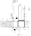
- the Figure 1 shows a baler for loose material to be pressed, such as B. paper or plastic waste as recycled goods, in a plan view.
- the baling press 1 has an upwardly open input area 2 into which the material to be pressed is input, for example via a belt conveyor.
- a press ram 3 can be moved by means of a hydraulic piston / cylinder drive 4 in the direction of a press chamber 5 in a press channel 6, with a press direction 10 having a Direction arrow in Figure 1 is indicated.
- the pressing direction 10 is oriented horizontally in this exemplary embodiment.
- a bale is produced in several working strokes of the ram 3.
- the in Figure 1 The bale shown in the pressing chamber 5 is almost complete.
- the compression chamber 5 is closed on all sides except for the side facing the compression ram 3 so that the compression pressure can be built up.
- the wall on the left in the pressing direction 10 is formed by a dispensing die 12, which also has a hydraulic drive 14 acting in a dispensing direction 13.
- the wall on the right in the pressing direction is formed by a wall part 15 that can be moved in a horizontal direction parallel to the pressing direction 10.
- a further hydraulic drive 16 is assigned to the wall part 15.
- the opening direction is oriented parallel and in the same direction as the pressing direction 10.
- the wall part 15 is in the Figure 1 shown in closed position. It closes the pressing chamber 5 with respect to a bale channel 18.
- the bale channel 18 is oriented transversely to the pressing channel 6 and, starting from the pressing direction 10, runs to the right.
- the ball channel is provided with a bandaging device 20.
- the bandaging device 20 is shown here as a wire tie with two supply reels 21 and 22.
- the wires are fetched by appropriate grippers 23 and a needle 24 in a manner known per se and twisted or knotted. In the top view of the Figure 1 only two wires can be seen. At right angles to the plane of the drawing, however, a plurality of wire pulls arranged in parallel, each with associated grippers and needles, are provided, about three to six depending on the bale size. Further in the discharge direction 13, an already finished and strapped bale 25 is shown in the bale channel 18.
- the Figure 2 shows the baler off Figure 1 in the same view.
- the press ram 3 has moved so far into the press channel 6 in the press direction 10 that the end face of the press ram 3 facing the material to be pressed is essentially aligned with the inner wall of the output channel 18.
- a second bale 26 was pressed.
- the wall part 15 is out of the output channel 18 by actuation of the drive 16 has been moved out, so that the cross section of the output channel 18 in the output direction 13 is free.
- the delivery stamp 12 was in the in Figure 2 Move the position shown.
- the bale 26 was pressed against the wire coming from the supply reel 21 and took it along in the output direction 13.
- the baler is in the Figure 3 in the same view as in the Figures 1 and 2 shown, so in a plan view.
- the position of the ram 3 is opposite Figure 2 unchanged.
- the output punch 12 is opposite to the output direction 13 back in the starting position of the Figure 1 drove.
- the dispensing ram 12 now again forms a delimiting wall of the pressing chamber 5.
- the wall part 15 is also back in the FIG Figure 1
- the starting position shown moves and forms a further wall of the pressing chamber 5 opposite the dispensing ram 12. In this position, the pressing chamber 5 is closed on all sides.
- the ram 3 is ready for another working stroke.
- the needle 24 of the bandaging device 20 is extended transversely through the bale channel 18 and grips with a barb the wire coming from the supply reel 21 between the supply reel 21 and the point at which the wire is inserted into the bale channel 18.
- the second bale 26 sits in the bale channel 18 and is wrapped with wire on its front face, which is front with respect to the discharge direction 13, and on the two long sides.
- the trailing end face of the bale 26 has not yet been strapped.
- a back expansion against the discharge direction 13 takes place only to a small extent, since this direction is oriented transversely to the pressing direction 10 and a back expansion would primarily take place in or against the pressing direction 10.
- Another position in the procedure is in the Figure 4 which in turn is a top view of the baler.
- the ram 3 has been withdrawn against the pressing direction 10, so that the input area 2 is again as in FIG Figure 1 free is.
- the other five side walls of the pressing chamber 5 are also in the starting position.
- the pressing process for producing the next bale in the pressing chamber 5 can therefore run again.
- the needle 24 was returned to the starting position of FIG Figure 1 proceed, the wire coming from the supply spool 21 being pulled across the bale channel 18. Since the needle 24 with the barb is pulled back into the bandaging device 20 so far that it also penetrates the course of the wire coming from the supply reel 22, this wire is also carried along a little in the direction of the bandaging device 20.
- the bandaging process has already been completed.
- the grippers 23 have gripped and twisted the wire sections lying in front of and behind the needle 24 in relation to the output direction 13, each gripper 23 having its own twisted area for connecting the wires drawn off from the supply reels 21 and 22.
- the wires were cut between the two twisted areas.
- bale 26 is thus completed and sits in the bale channel 18, where it serves as a resistance for the next bale, which is a partial bale 27 in Fig. 5 is indicated.
- each bale 26 is provided with a total of five bandages which wrap around the bale on its front side, its two long sides and its rear side, based on the dispensing direction 13, and thus keep it in shape.
- the press ram 3 is initially in its initial position, which is fixed against the press direction 10. This position is in the Figures 1 , 4th and 5 shown.
- Loose material to be pressed can now be placed in input area 2.
- the material to be pressed is pressed into the pressing chamber 5 by the press ram 3 in one working stroke, where it forms a first partial bale which fills, for example, 20% of the pressing chamber 5. Four more strokes then fill the baling chamber to almost 100%.
- the ram 3 After the last working stroke, the ram 3 remains in the in Figure 2 The position shown and the wall part 15 is moved out of the bale channel 18 by the drive 16, so that the pressing chamber 5 opens towards the bale channel 18.
- the dispensing ram 12 is then moved in the dispensing direction 13 by the drive 14 and pushes the bale that has just been produced into the bale channel 18, to the extent that the rear face of the bale comes behind the working area of the needle 24.
- the bale moved forward in the bale channel 18 takes the wire coming from the supply reel 21 with it, as well as the wire coming from the supply reel 22, since the two wires are connected to one another by a twist.
- the total of five needles 24 in this exemplary embodiment execute their working stroke transversely through the bale channel 18 as soon as the backward movement of the press ram 12 releases the area of the bale channel 18 required for this.
- a barb per needle 24 engages behind the wire coming from the supply roll 21 and pulls it during the backward movement across the bale channel 18.
- the second wire coming from the supply roll 22 is also taken along.
- Each needle 24 is assigned two grippers 23, which now grasp and twist the wires lying in front of and behind the needle. Then cut like wires between the two twists. The ball formation and bandaging process is now complete.
- a major advantage of this baler is that the bandaging process is carried out in the bale channel, specifically at a position that does not interfere with the press chamber and in particular with the movable wall part of the press chamber. The baling of the next bale can therefore already begin when the banding has not yet been completed. It can be seen that this shortens the cycle time of the baling press and increases throughput.
- bandages with metal wire can be provided, but bandages with bands or monofilaments made of plastic can also be provided.
- bandaging device 20 is a self-contained assembly and the location of the bandaging allows freedom in the arrangement, various bandaging devices can also be provided which can either remain permanently installed and can be controlled as required, or which can be exchanged as an assembly in a short time . In this way, the type of bandaging can be adapted to the changed requirements of the customer or the material to be pressed.
Landscapes
- Engineering & Computer Science (AREA)
- Mechanical Engineering (AREA)
- Life Sciences & Earth Sciences (AREA)
- Environmental Sciences (AREA)
- Basic Packing Technique (AREA)
Description
- Die vorliegende Erfindung betrifft eine Ballenpresse und ein Verfahren zur Verwendung der Ballenpresse.
- Ballenpressen werden eingesetzt, um loses Material wie zum Beispiel Papier und Pappe, Kunststoffabfälle, gemischte Abfälle oder Fasermaterialien zu quaderförmigen Ballen zu verpressen, die dann mit verschiedenartigen Abbindungen versehen werden können. Die Ballen können dann gestapelt und transportiert werden, wobei der Platzbedarf und der Aufwand beim Handling deutlich verringert ist.
- Es gibt verschiedene Bauformen von Ballenpressen. Neben Kanal-Ballenpressen mit einer zweiseitig offenen Presskammer und einem nachfolgenden Presskanal, in dem dort befindliche Ballen als Widerlager für den Pressvorgang genutzt werden, gibt es auch die gattungsgemäßen Ballenpressen mit einer einseitig offenen Presskammer, die sich durch eine bessere Formhaltung der erzeugten Ballen und durch eine kürzere Bauform auszeichnen.
- Gattungsgemäße Ballenpressen sind beispielsweise aus der
DE 69506769 T2 und derDE 20 2012 010 760 U1 bekannt. Letztere bildet den nächstkommenden Stand der Technik, bei dem das Pressgut nach dem Pressen quer zur Pressrichtung in einen Ballenkanal verpresst wird und dort von einer separaten Vorschubeinrichtung schrittweise durch eine Bandagiereinrichtung gefördert wird. Die Bandagiereinrichtung umreift den Ballen an seinen äußeren Umfangsflächen, also bezogen auf die Förderrichtung in dem Ballenkanal an den beiden Seitenflächen, der Oberseite und der Unterseite. In Förderrichtung bleiben die Vorderseite und die Rückseite des Ballens frei von Bandagierung. - Der Abstand der Bandagierungen auf dem Ballen entspricht jeweils der Schrittweite, die durch die Fördereinrichtung in dem Ballenkanal vorgegeben ist.
- Während die Bandagierung am Ende des Ballenkanals erfolgt und der schrittweise Vorschub in dem Ballenkanal vorgenommen wird, kann die Ballenpresse selbst bereits weitere Presshübe ausführen. Hierbei ist allerdings erforderlich, dass der Antrieb der Presse, der üblicherweise hydraulisch erfolgt, simultan die Antriebsleistung für den Presshub und für den schrittweisen Vorschub in dem Ballenkanal erzeugen kann. Die
DE 26 56 457 A1 beschreibt eine weitere Ballenpresse für loses Pressgut mit einem Füllschacht und einem Press- und Ausgabestempel, der den Ballen nach einem Pressvorgang in einer Ausgaberichtung aus einem Presskasten befördert, wobei der Presskasten einen Trennschieber aufweist gegen den das Pressgut komprimiert wird. Die Druckschrift beschreibt ferner eine Bandagiereinrichtung zur Umreifung des in dem Pressvorgang geformten Ballens, die den Ballenkanal in Querrichtung durchgreifende Schnürnadeln aufweist. Der Hub des Press- und Ausgabestempels reicht bis hinter die Schnürnadeln, so dass der Ballen durch die Bandagiereinrichtung befördert wird. - Die
DE 20 2012 010760 U1 beschreibt eine weitere Ballenpresse, bei der mittels eines Pressstempels loses Pressgut in einem Kasten komprimiert wird, der während der Kompression durch eine Schiebewand in Ausschubrichtung hinter dem Kasten begrenzt wird. Der Kompressionskasten liegt räumlich im Ausstoßkanal. Das Ausstoßen erfolgt mittels einer Ausstoßwand. Beim Ausstoßen scheint keine Komprimierung zu erfolgen sondern lediglich eine Ausschubbewegung. Der Hub der Ausstoßwand endet in Ausstoßrichtung kurz hinter der Schiebewand vor einer Bandagiervorrichtung. - Die
US 2009/272282 A1 beschreibt eine Ballenpresse, bei der eine Kompression des losen Pressguts in einem Presskanal erfolgt. Die Kompression im Presskanal erfolgt mittels eines Stempels gegen den Reibungswiderstand der in Pressrichtung hinter dem zu komprimierenden Pressgut liegenden Ballen, die bereits komprimiert und gebündelt sind. Eine Vorkomprimierung erfolgt über eine schwenkbare Klappe. - Die
EP 2 014 455 A1 beschreibt eine Ballenpresse bei der mittels einer Pressplatte loses Pressgut in einem Kasten komprimiert wird, der während der Kompression durch eine zu öffnende Tür in Ausschubrichtung hinter dem Kasten begrenzt wird. Der Kompressionskasten liegt räumlich in einem Bereich, der als Ausstoßkanal bezeichnet werden kann. Das Ausstoßen erfolgt mittels einer Ausstoßwand. Der Hub der Ausstoßwand endet in Ausstoßrichtung kurz hinter der zu öffnenden Tür. - Es ist deshalb Aufgabe der vorliegenden Erfindung, eine gattungsgemäße Ballenpresse dahingehend zu verbessern, dass der Antrieb der Presse kleiner ausgelegt werden kann. Es ist außerdem Aufgabe der vorliegenden Erfindung, eine gattungsgemäße Ballenpresse und ein Arbeitsverfahren bereitzustellen, die eine kürzere Taktzeit erlauben.
- Diese Aufgabe wird von einer Ballenpresse mit den Merkmalen des Anspruchs 1 und von einem Verfahren mit den Merkmalen des Anspruchs 9 gelöst.
- Weil bei einer gattungsgemäßen Ballenpresse der Arbeitshub des Ausgabestempels in Ausgaberichtung bis hinter die wenigstens eine Nadel der Bandagiereinrichtung reicht, so dass der Ausgabestempel bei einem vollständigen Arbeitshub den Ballen durch die Bandagiereinrichtung befördert, kann auf separate Mitnehmer zur Beförderung des Ballens in dem Ballenkanal verzichtet werden.
- Wenn der Ausgabestempel der einzige Antrieb zur Förderung des Ballens in Ausgaberichtung bis zur Fertigstellung der Umreifung ist, wird durch den Wegfall der Mitnehmer die Presse insgesamt einfacher. Es ergeben sich aber auch Vorteile hinsichtlich der Arbeitsgeschwindigkeit.
- Die Bandagiereinrichtung ist bevorzugt so ausgebildet, dass sie Bandagen an die in Ausgaberichtung vordere Stirnseite und die in Ausgaberichtung hintere Rückseite sowie an zwei Seitenflächen des Ballens anlegt. Dadurch wird die Bandagierung besonders schnell anzufertigen.
- Wenn die Bandagiereinrichtung dazu eingerichtet ist, zwei oder mehr, insbesondere vier bis sechs Bandagen simultan an die Ballen anzulegen, wird der Ballen besonders fest bandagiert, ohne dass die Taktzeit dadurch verlängert wird.
- Vorzugsweise ist die Bandagiereinrichtung dazu eingerichtet, wahlweise Bandagen aus Metall oder aus einem Kunststoff an die Ballen anzulegen. Es können dann Ballen für verschiedene Zwecke ohne lange Umrüstzeiten gefertigt werden. Beispielsweise können Altpapierballen mit Draht umreift werden, während Kunststoffabfälle mit einem Kunststoffband umreift werden können. Dies ist für die spätere Verwertung vorteilhaft. Dies wird dadurch möglich, dass die Bandagiereinrichtung in einem Bereich der Ballenpresse angeordnet ist, in dem sie geringen Einschränkungen hinsichtlich Platzbedarf und Zugänglichkeit unterliegt.
- Vorzugsweise ist die Bandagiereinrichtung dazu eingerichtet, die Bandagen in horizontaler Richtung an die Ballen anzulegen, weil dann kein Bauraum in der vertikalen Richtung über oder unter dem Ballenkanal erforderlich ist.
- Es ist weiter bevorzugt, wenn die Bandagen von einer Anzahl von Vorratsspulen abgezogen werden. Durch einfachen Wechsel der Vorratsspulen kann dann innerhalb gewisser Grenzen das Bandagiermaterial variiert werden.
- Ein erfindungsemäßes Verfahren erfolgt mittels einer Ballenpresse wie vorstehend beschrieben. Weil bei einem gattungsgemäßen Verfahren der Ballen in einem auf das Bandagieren abgestimmten Vorschub aus der Presskammer heraus und durch eine zwischen der Presskammer und dem Ballenkanal angeordnete Bandagiereinrichtung zumindest bis hinter den Arbeitsbereich der in einer solchen Bandagiereinrichtung vorhandenen Nadeln bewegt wird, werden die oben beschriebenen Vorteile erzielt, insbesondere durch Wegfall eines Schrittes zur Übergabe des Ballens von dem Ausgabestempel zu einer Mitnehmereinrichtung.
- Vorzugsweise erfolgt das Bandagieren an der vorderen Stirnseite und an den Seitenflächen während des Vorschubs. Dies erhöht die mögliche Arbeitsgeschwindigkeit.
- Ein kompakter und wartungsfreundlicher Aufbau ergibt sich, wenn das Bandagieren parallel zu einer Ebene erfolgt, die durch die Pressrichtung und die Ausgaberichtung aufgespannt wird.
- Die Arbeitsgeschwindigkeit wird weiter verbessert, wenn bei dem Bandagieren zwei oder mehr Bandagen simultan erzeugt werden. Bevorzugt sind vier bis sechs parallele Bandagen vorgesehen.
- Es ist insbesondere vorteilhaft, wenn bei dem erfindungsgemäßen Verfahren die zwei oder mehr Bandagen aus Metalldraht oder Kunststoffdraht erzeugt werden.
- Nachfolgend wird ein Ausführungsbeispiel der vorliegenden Erfindung anhand der Zeichnung näher beschrieben. Es zeigen:
- Figur 1:
- eine erfindungsgemäße Ballenpresse in einer schematischen Darstellung in Draufsicht vor einem Verdichtungshub;
- Figur 2:
- die Ballenpresse nach
Figur 1 während des Ausschiebens des verpressten Ballenmaterials; - Figur 3:
- die Ballenpresse nach
Figur 1 undFigur 2 während des Bandagierens des Ballens; - Figur 4:
- die Ballenpresse nach
Figur 3 bei weiter fortgeschrittener Bandagierung; - Figur 5:
- die Ballenpresse nach
Figur 4 mit fertig gestellter Bandagierung; sowie - Figur 6:
- die Ballenpresse nach
Figur 3 in einer Seitenansicht. - Die
Figur 1 zeigt eine Ballenpresse für loses Pressgut, wie z. B. Papier- oder Kunststoffabfälle als Recyclinggut, in einer Draufsicht. Die Ballenpresse 1 weist einen nach oben offenen Eingabebereich 2 auf, in den das Pressgut beispielsweise über einen Bandförderer eingegeben wird. Ein Pressstempel 3 ist mittels eines hydraulischen Kolben/Zylinderantriebs 4 in Richtung einer Presskammer 5 in einem Presskanal 6 verfahrbar, wobei eine Pressrichtung 10 mit einem Richtungspfeil inFigur 1 angedeutet ist. Die Pressrichtung 10 ist bei diesem Ausführungsbeispiel horizontal orientiert. - Ein Ballen wird in mehreren Arbeitshüben des Pressstempels 3 erzeugt. Der in
Figur 1 dargestellte Ballen in der Presskammer 5 ist nahezu fertiggestellt. - Die Presskammer 5 ist bis auf die dem Pressstempel 3 zugewandte Seite allseits geschlossen, damit der Verdichtungsdruck aufgebaut werden kann. Die in Pressrichtung 10 linke Wand wird von einem Ausgabestempel 12 gebildet, der ebenfalls über einen in einer Ausgaberichtung 13 wirkenden hydraulischen Antrieb 14 verfügt. Die in Pressrichtung rechte Wand ist von einem Wandteil 15 gebildet, dass in einer horizontalen Richtung parallel zu der Pressrichtung 10 verfahrbar ist. Dazu ist dem Wandteil 15 ein weiterer hydraulischer Antrieb 16 zugeordnet. Die Öffnungsrichtung ist in diesem Ausführungsbeispiel parallel und gleichsinnig zu der Pressrichtung 10 orientiert.
- Das Wandteil 15 ist in der
Figur 1 in geschlossener Stellung dargestellt. Es verschließt die Presskammer 5 gegenüber einem Ballenkanal 18. Der Ballenkanal 18 ist quer zu dem Presskanal 6 ausgerichtet und verläuft, ausgehend von der Pressrichtung 10, nach rechts. Der Ballenkanal ist mit einer Bandagiereinrichtung 20 versehen. Die Bandagiereinrichtung 20 ist hier als Drahtabbindung mit zwei Vorratsspulen 21 und 22 dargestellt. Die Drähte werden von entsprechenden Greifern 23 und einer Nadel 24 in an sich bekannter Weise geholt und verdrillt bzw. verknotet. In der Draufsicht derFigur 1 sind nur zwei Drähte erkennbar. Senkrecht zur Zeichenebene sind jedoch mehrere parallel angeordnete Drahtzüge mit jeweils zugeordneten Greifern und Nadeln vorgesehen, je nach Ballengröße etwa drei bis sechs. Weiter in Ausgaberichtung 13 ist in dem Ballenkanal 18 ein bereits fertiggestellter und umreifter Ballen 25 dargestellt. - Die
Figur 2 zeigt die Ballenpresse ausFigur 1 in derselben Ansicht. In dieser Darstellung ist der Pressstempel 3 so weit in Pressrichtung 10 in den Presskanal 6 eingefahren, das die dem Pressgut zugewandte Stirnfläche des Pressstempels 3 im Wesentlichen mit der Innenwand des Ausgabekanals 18 fluchtet. In diesem Verfahrensschritt wurde ein zweiter Ballen 26 gepresst. Das Wandteil 15 ist aus dem Ausgabekanal 18 durch Betätigung des Antriebs 16 herausgefahren worden, so dass der Querschnitt des Ausgabekanals 18 in der Ausgaberichtung 13 frei ist. Durch Betätigung des Antriebs 14 wurde der Ausgabestempel 12 in die inFigur 2 dargestellte Position verfahren. Dabei wurde der Ballen 26 gegen den von der Vorratsspule 21 kommenden Draht gedrückt und hat diesen in Ausgaberichtung 13 mitgenommen. Auch der von der Vorratsspule 22 kommende Draht, der mit dem von der Vorratsspule 21 kommenden Draht verdrillt oder verknotet ist, wurde von dem Ballen 26 in der Ausgaberichtung 13 mitgenommen. Die beiden Drähte liegen nun an dem Ballen 26 an der bezüglich der Ausgaberichtung 13 voreilenden Stirnseite und an der rechten und der linken Längsseite an. - Die Ballenpresse wird in der
Figur 3 in derselben Ansicht wie in denFiguren 1 und2 dargestellt, also in einer Draufsicht. Die Position des Pressstempels 3 ist gegenüberFigur 2 unverändert. Der Ausgabestempel 12 ist entgegen der Ausgaberichtung 13 zurück in die Ausgangsposition derFigur 1 gefahren. Der Ausgabestempel 12 bildet nun wieder eine Begrenzungswand der Presskammer 5. Auch das Wandteil 15 ist wieder in die inFigur 1 dargestellte Ausgangsstellung verfahren und bildet eine weitere, dem Ausgabestempel 12 gegenüber liegende Wand der Presskammer 5. In dieser Stellung ist die Presskammer 5 allseitig geschlossen. Der Pressstempel 3 ist bereit für einen weiteren Arbeitshub. Im Ballenkanal 18 ist die Nadel 24 der Bandagiereinrichtung 20 quer durch den Ballenkanal 18 ausgefahren und ergreift mit einem Widerhaken den von der Vorratsspule 21 kommenden Draht zwischen der Vorratsspule 21 und dem Punkt, an dem der Draht in den Ballenkanal 18 eingeführt wird. Der zweite Ballen 26 sitzt in dieser Situation in dem Ballenkanal 18 und ist an seiner bezüglich der Ausgaberichtung 13 vorderen Stirnseite sowie an den beiden Längsseiten mit Draht umschlungen. Die nacheilende Stirnseite des Ballens 26 ist noch nicht umreift. Eine Rückexpansion entgegen der Ausgaberichtung 13 findet jedoch nur in geringem Maß statt, da diese Richtung quer zu der Pressrichtung 10 orientiert ist und eine Rückexpansion in erster Linie in oder entgegen der Pressrichtung 10 erfolgen würde. Eine weitere Stellung im Verfahrensablauf ist in derFigur 4 dargestellt, die wiederum eine Draufsicht auf die Ballenpresse ist. - Der Pressstempel 3 ist entgegen der Pressrichtung 10 zurückgezogen worden, sodass der Eingabebereich 2 wieder wie in
Figur 1 frei ist. Die anderen fünf Seitenwände der Presskammer 5 sind ebenfalls in der Ausgangsposition. Der Pressvorgang zur Erzeugung des nächsten Ballens in der Presskammer 5 kann also erneut ablaufen. Gleichzeitig wurde die Nadel 24 von dem Antrieb der Bandagiereinrichtung 20 zurück in die Ausgangsstellung derFigur 1 verfahren, wobei der Draht, der von der Vorratsspule 21 kommt, quer durch den Ballenkanal 18 gezogen wurde. Da die Nadel 24 mit dem Widerhaken so weit in die Bandagiereinrichtung 20 zurück gezogen wird, dass sie auch den Verlauf des von der Vorratsspule 22 kommenden Drahtes durchsetzt, wird auch dieser Draht ein Stück weit in Richtung auf die Bandagiereinrichtung 20 mitgenommen. - Bemerkenswert ist hier, dass der Vorgang des Bandagierens noch nicht abgeschlossen ist, während die Presseinrichtung mit dem Pressstempel 3 und der Presskammer 5 bereits wieder für den nächsten Arbeitshub bereit ist und das Pressgut verdichtet werden kann. Die Erzeugung des Ballens in der Presskammer 5 ist also zeitlich entkoppelt von dem Bandagieren, das im Ballenkanal 18 erfolgt.
- In der
Figur 5 ist der Abschluss des Bandagiervorgangs bereits erfolgt. Die Greifer 23 haben die bezüglich der Ausgaberichtung 13 vor und hinter der Nadel 24 liegenden Drahtabschnitte ergriffen und verdrillt, wobei jeder Greifer 23 einen eigenen verdrillten Bereich zur Verbindung der von den Vorratsspulen 21 und 22 abgezogenen Drähte erzeugt hat. Zwischen den beiden verdrillten Bereichen wurden die Drähte durchtrennt. - Der Ballen 26 ist somit fertiggestellt und sitzt in dem Ballenkanal 18, wo er als Widerstand für den nächsten Ballen dient, der als Teilballen 27 in
Fig. 5 angedeutet ist. - Schließlich zeigt die
Figur 6 einen Längsschnitt etwa entlang der Linie VI-VI ausFigur 1 . Die Ansicht ist in Richtung der Ausgaberichtung 13 orientiert. Die Pressrichtung 10 und der Arbeitshub der Nadeln 24 verlaufen parallel zu der Zeichenebene. Die Bandagiereinrichtung 20 ist mit insgesamt fünf Nadeln 24 und entsprechend zehn Greifern 23 versehen, die parallel zueinander angeordnet sind und einen Abstand voneinander aufweisen, der so gewählt ist, dass über den Querschnitt des Ausgabekanals 18 die Bandagierungen gleichmäßig verteilt sind. In dem vorliegenden Ausführungsbeispiel wird jeder Ballen 26 mit insgesamt fünf Bandagierungen versehen, die den Ballen an seiner Vorderseite, seinen beiden Längsseiten und seiner Rückseite, bezogen auf die Ausgaberichtung 13, umschlingen und damit in Form halten. - Im Folgenden soll der Verfahrensablauf zur Fertigung von gepressten Ballen aus Pressgut wie zum Beispiel Papier-und Kunststoffabfällen im Zusammenhang erläutert werden.
- Ausgehend von einem leeren Presskanal 6 und einem leeren Pressraum 5 ist der Pressstempel 3 zunächst in seiner Anfangsposition, die entgegen der Pressrichtung 10 festgelegt ist. Diese Position ist in den
Figuren 1 ,4 und5 dargestellt. Loses Pressgut kann nun in den Eingabebereich 2 gegeben werden. Das Pressgut wird in einem Arbeitshub von den Pressstempel 3 in die Presskammer 5 gepresst und bildet dort einen ersten Teilballen, der beispielsweise 20 % der Presskammer 5 ausfüllt. Vier weitere Arbeitshübe füllen dann die Presskammer zu nahezu 100 %. - Nach dem letzten Arbeitshub bleibt der Pressstempel 3 in der in
Figur 2 dargestellten Position und das Wandteil 15 wird von dem Antrieb 16 aus dem Ballenkanal 18 heraus gefahren, sodass sich die Presskammer 5 zu dem Ballenkanal 18 hin öffnet. Der Ausgabestempel 12 wird dann von dem Antrieb 14 in der Ausgaberichtung 13 bewegt und stößt den soeben gefertigten Ballen in den Ballenkanal 18, und zwar so weit, dass die rückwärtige Stirnseite des Ballens hinter den Arbeitsbereich der Nadel 24 kommt. Der so in dem Ballenkanal 18 vorwärts bewegte Ballen nimmt den von der Vorratsspule 21 kommenden Draht mit, ebenso den von der Vorratsspule 22 kommenden Draht, da die beiden Drähte durch eine Verdrillung miteinander verbunden sind. - Nun fährt der Pressstempel 12 entgegen der Ausgaberichtung 13 zurück in seine Ausgangsstellung gemäß
Figur 1 . Das Wandteil 15 wird ebenfalls in die Ausgangsstellung zurückgefahren, so dass die Presskammer 5 nun wieder geschlossen und bereit für die Anfertigung der folgenden Teilballen ist. - Die in diesem Ausführungsbeispiel insgesamt fünf Nadeln 24 führen ihren Arbeitshub quer durch den Ballenkanal 18 aus, sobald die Rückwärtsbewegung des Pressstempels 12 den dafür erforderlichen Bereich des Ballenkanals 18 frei gibt.
- Ein Widerhaken pro Nadel 24 greift dabei hinter den von der Vorratsrolle 21 kommenden Draht und zieht diesen bei der Rückwärtsbewegung quer durch den Ballenkanal 18. Am Ende der Rückwärtsbewegung der Nadel 24 wird auch noch der zweite Draht, der von der Vorratsrolle 22 kommt, mitgenommen. Jeder Nadel 24 sind zwei Greifer 23 zugeordnet, die nun die vor und hinter der Nadel liegenden Drähte ergreifen und verdrillen. Danach werden wie Drähte zwischen den beiden Verdrillungen aufgetrennt. Der Vorgang der Ballenformung und Bandagierung ist damit abgeschlossen.
- Ein wesentlicher Vorteil dieser Ballenpresse besteht darin, dass der Vorgang des Bandagierens in dem Ballenkanal durchgeführt wird, und zwar an einer Position, die mit der Presskammer und insbesondere dem beweglichen Wandteil der Presskammer nicht interferiert. Das Pressen den nächstfolgenden Ballens kann deshalb bereits beginnen, wenn das Bandagieren noch nicht abgeschlossen ist. Es ist ersichtlich, dass sich dadurch die Taktzeit der Ballenpresse verkürzen und der Durchsatz steigern lässt.
- Die Art der Bandagierung ist dabei nicht festgelegt. Es können wie in dem beschriebenen Ausführungsbeispiel Drahtbandagierungen mit Metalldraht vorgesehen sein, aber auch Bandagierungen mit Bändern oder Monofilamenten aus Kunststoff.
- Da die Bandagierungseinrichtung 20 eine abgeschlossene Baugruppe darstellt und der Ort der Bandagierung Freiheiten in der Anordnung lässt, können auch verschiedene Bandagiervorrichtungen vorgesehen sein, die entweder dauerhaft montiert bleiben können und jeweils nach Bedarf angesteuert werden können, oder die als Baugruppe in kurzer Zeit ausgewechselt werden können. So kann man die Art der Bandagierung an geänderte Anforderungen der Abnehmer oder des Pressguts anpassen.
Claims (13)
- Ballenpresse (1) für loses Pressgut,- mit einem Eingabebereich (2) und- einem Pressstempel (3), der dazu eingerichtet ist, das Pressgut von dem Eingabebereich (2) in einer Pressrichtung (10) in eine einseitig offene Presskammer (5) zu pressen,- mit einem Ausgabestempel (12), der den Ballen (25, 26) nach dem Pressvorgang in einer Ausgaberichtung (13) aus der Presskammer (5) befördert,- mit einem Ballenkanal (18), der eine Eintrittsöffnung und eine Austrittsöffnung aufweist und der sich von der Presskammer (5) in der Ausgaberichtung (13) quer zu der Pressrichtung (10) erstreckt,- wobei die Presskammer (5) eine der Eintrittsöffnung des Ballenkanals (18) zugewandte, nach dem Pressvorgang zu öffnende Seitenwand (15) aufweist,- und mit einer Bandagiereinrichtung (20) zur Umreifung des in dem Pressvorgang geformten Ballens (25, 26), die wenigstens eine bei einem Arbeitshub den Ballenkanal in Querrichtung durchgreifende Nadel (24) aufweist, wobei- der Arbeitshub des Ausgabestempels (12) in Ausgaberichtung (13) bis hinter die wenigstens eine Nadel (24) der Bandagiereinrichtung (20) reicht, so dass der Ausgabestempel (12) den Ballen (25, 26) durch die Bandagiereinrichtung (20) befördert.
- Ballenpresse nach Anspruch 1, dadurch gekennzeichnet, dass die Bandagiereinrichtung (20) in der Ausgaberichtung (13) zwischen der Eintrittsöffnung und der Austrittsöffnung des Ballenkanals (18) angeordnet ist.
- Ballenpresse nach einem der vorhergehenden Ansprüche, dadurch gekennzeichnet, dass der Ausgabestempel (12) der einzige Antrieb zur Förderung des Ballens (25, 26) in Ausgaberichtung (13) bis zur Fertigstellung der Umreifung ist.
- Ballenpresse nach einem der vorhergehenden Ansprüche, dadurch gekennzeichnet, dass die Bandagiereinrichtung (20) Bandagen an die in Ausgaberichtung (13) vordere Stirnseite und die in Ausgaberichtung hintere Rückseite sowie an zwei Seitenflächen des Ballens (25, 26) anlegt.
- Ballenpresse nach einem der vorhergehenden Ansprüche, dadurch gekennzeichnet, dass die Bandagiereinrichtung (20) dazu eingerichtet ist, zwei oder mehr Bandagen simultan an die Ballen (25, 26) anzulegen.
- Ballenpresse nach einem der vorhergehenden Ansprüche, dadurch gekennzeichnet, dass die Bandagiereinrichtung (20) dazu eingerichtet ist, wahlweise Bandagen aus Metall oder aus einem Kunststoff an die Ballen (25, 26) anzulegen.
- Ballenpresse nach einem der vorhergehenden Ansprüche, dadurch gekennzeichnet, dass die Bandagiereinrichtung (20) dazu eingerichtet ist, die Bandagen in horizontaler Richtung an die Ballen (25, 26) anzulegen.
- Ballenpresse nach einem der vorhergehenden Ansprüche, dadurch gekennzeichnet, dass die Bandagen von einer Anzahl von Vorratsspulen (21, 22) abgezogen werden.
- Verfahren zum Pressen von losem Pressgut zu Ballen (25, 26) und zum Bandagieren der gepressten Ballen (25, 26) mittels einer Ballenpresse gemäß einem der Ansprüche 1-8, bei dem das lose eingegebene Pressgut in eine seitlich zu öffnende Presskammer (5) mit einer vorgegebenen Pressrichtung (10) zu Ballen (25, 26) gepresst und dann mittels eines Ausgabestempels (13) quer zur Pressrichtung (10) in einen Ballenkanal (18) und zu einer Bandagiereinrichtung (20) ausgepresst wird, dadurch gekennzeichnet, dass der Ballen (25, 26) in einem auf das Bandagieren abgestimmten Vorschub aus der Presskammer (5) heraus und durch eine zwischen der Presskammer (5) und dem Ballenkanal (18) angeordnete Bandagiereinrichtung (20) bewegt wird.
- Verfahren nach Anspruch 9, dadurch gekennzeichnet, dass das Bandagieren an der vorderen Stirnseite und an den Seitenflächen während des Vorschubs erfolgt.
- Verfahren nach Anspruch 9 oder 10, dadurch gekennzeichnet, dass das Bandagieren parallel zu einer Ebene erfolgt, die durch die Pressrichtung (10) und die Ausgaberichtung (13) aufgespannt wird.
- Verfahren nach einem der vorhergehenden Ansprüche 9 bis 11, dadurch gekennzeichnet, dass bei dem Bandagieren zwei oder mehr Bandagen simultan erzeugt werden.
- Verfahren nach einem der vorhergehenden Ansprüche 9 bis 12, dadurch gekennzeichnet, dass die zwei oder mehr Bandagen aus Metalldraht oder Kunststoffdraht erzeugt werden.
Priority Applications (1)
| Application Number | Priority Date | Filing Date | Title |
|---|---|---|---|
| PL17199144T PL3326451T3 (pl) | 2016-11-29 | 2017-10-30 | Prasa do belowania do luźnego materiału prasowanego |
Applications Claiming Priority (1)
| Application Number | Priority Date | Filing Date | Title |
|---|---|---|---|
| DE102016014198.0A DE102016014198A1 (de) | 2016-11-29 | 2016-11-29 | Ballenpresse für loses Pressgut |
Publications (2)
| Publication Number | Publication Date |
|---|---|
| EP3326451A1 EP3326451A1 (de) | 2018-05-30 |
| EP3326451B1 true EP3326451B1 (de) | 2021-11-24 |
Family
ID=60191249
Family Applications (1)
| Application Number | Title | Priority Date | Filing Date |
|---|---|---|---|
| EP17199144.1A Active EP3326451B1 (de) | 2016-11-29 | 2017-10-30 | Ballenpresse für loses pressgut |
Country Status (4)
| Country | Link |
|---|---|
| EP (1) | EP3326451B1 (de) |
| DE (1) | DE102016014198A1 (de) |
| ES (1) | ES2906642T3 (de) |
| PL (1) | PL3326451T3 (de) |
Families Citing this family (1)
| Publication number | Priority date | Publication date | Assignee | Title |
|---|---|---|---|---|
| CN113998179B (zh) * | 2021-11-01 | 2023-02-21 | 安徽银山阻燃新材料科技有限公司 | 一种对前脱脂水刺无纺布生产用原料打包的打包设备 |
Family Cites Families (7)
| Publication number | Priority date | Publication date | Assignee | Title |
|---|---|---|---|---|
| DD96045A1 (de) * | 1972-04-26 | 1973-03-05 | Horizontale hochleistungs-ballenpresse, vorzugsweise für papier- und textilabfälle alle art | |
| DE2656457C3 (de) * | 1976-12-14 | 1981-04-16 | Lindemann Maschinenfabrik GmbH, 4000 Düsseldorf | Ballenpresse |
| ES2112124B1 (es) | 1994-04-15 | 1998-10-01 | Lopez Ramirez Miguel | Procedimiento para la confeccion de balas de materiales disgregados y aparato para su realizacion. |
| DE4416584A1 (de) * | 1994-05-11 | 1995-11-16 | Lindemann Maschfab Gmbh | Verfahren zum Betreiben einer Ballenpresse und Ballenpresse |
| EP2014455B1 (de) * | 2007-07-13 | 2014-08-20 | Amadeo Farell S.A.U. | Maschine zur Formung von Ballen aus desintegriertem Material |
| US7849790B2 (en) * | 2008-05-02 | 2010-12-14 | Industries Machinex Inc. | Single ram baler |
| DE202012010760U1 (de) | 2012-11-12 | 2014-02-14 | Unotech Gmbh | Ballenpresse für loses Pressgut |
-
2016
- 2016-11-29 DE DE102016014198.0A patent/DE102016014198A1/de not_active Withdrawn
-
2017
- 2017-10-30 ES ES17199144T patent/ES2906642T3/es active Active
- 2017-10-30 PL PL17199144T patent/PL3326451T3/pl unknown
- 2017-10-30 EP EP17199144.1A patent/EP3326451B1/de active Active
Non-Patent Citations (1)
| Title |
|---|
| None * |
Also Published As
| Publication number | Publication date |
|---|---|
| EP3326451A1 (de) | 2018-05-30 |
| DE102016014198A1 (de) | 2018-05-30 |
| ES2906642T3 (es) | 2022-04-19 |
| PL3326451T3 (pl) | 2022-05-02 |
Similar Documents
| Publication | Publication Date | Title |
|---|---|---|
| EP2668027A1 (de) | Ballenpresse und verfahren zur herstellung verdichteter pressbalen aus faser material | |
| DE2709248C2 (de) | Verfahren und Vorrichtung zum Umschnüren von Ballen | |
| WO2014072028A1 (de) | Ballenpresse für loses pressgut | |
| EP1190618B1 (de) | Ballenpresse für loses Pressgut | |
| EP4091808B1 (de) | Verfahren zum verändern der umreifung sowie ballenpresse zur anwendung dieses verfahrens | |
| DE102022121422A1 (de) | Verfahren zum Verändern der Umreifung sowie Ballenpresse zur Anwendung dieses Verfahrens | |
| DE102012008554A1 (de) | Kanalballenpresse | |
| EP3199331B1 (de) | Ballenpresse | |
| EP4261028B1 (de) | Kanalballenpresse mit kreuzabbindung | |
| EP1922210A1 (de) | Verfahren und vorrichtung zur herstellung von pressballen | |
| EP2478757B1 (de) | Ballenpresse | |
| EP3665086B1 (de) | Verpackungseinrichtung und verpackungsverfahren | |
| DE102009040506B4 (de) | Ballenpresse | |
| EP3326451A1 (de) | Ballenpresse für loses pressgut | |
| DE102005003397A1 (de) | Kanalballenpresse | |
| DE10111829B4 (de) | Vorrichtung und Verfahren zum Pressen von mindestens einem Fasermaterialkörper | |
| EP2660160A2 (de) | Kanalballenpresse | |
| DE4022324A1 (de) | Ballenpresse zum erstellen hochverdichteter, abgebundener ballen aus abfallmaterialien | |
| DE102017010639A1 (de) | Presse und Verfahren zur Erzeugung von rechteckigen Ballen | |
| EP0589257A1 (de) | Ballenpresse, insbesondere zur Verdichtung von Verpackungsmaterial | |
| EP1254840B1 (de) | Ballenpresse | |
| EP3882166B1 (de) | Verfahren zum einfädeln des unteren umreifungs-stranges sowie ballenpresse zur anwendung dieses verfahrens | |
| DE4203360A1 (de) | Vorrichtung zum abbinden von pressballen mit hilfe von bindematerial | |
| DE102023129957A1 (de) | Sequentielle Abbindung von verpresstem Material und so hergestellte Ballen | |
| DE102005042217A1 (de) | Verfahren und Vorrichtung zur Herstellung von Pressballen |
Legal Events
| Date | Code | Title | Description |
|---|---|---|---|
| PUAI | Public reference made under article 153(3) epc to a published international application that has entered the european phase |
Free format text: ORIGINAL CODE: 0009012 |
|
| STAA | Information on the status of an ep patent application or granted ep patent |
Free format text: STATUS: THE APPLICATION HAS BEEN PUBLISHED |
|
| AK | Designated contracting states |
Kind code of ref document: A1 Designated state(s): AL AT BE BG CH CY CZ DE DK EE ES FI FR GB GR HR HU IE IS IT LI LT LU LV MC MK MT NL NO PL PT RO RS SE SI SK SM TR |
|
| AX | Request for extension of the european patent |
Extension state: BA ME |
|
| STAA | Information on the status of an ep patent application or granted ep patent |
Free format text: STATUS: REQUEST FOR EXAMINATION WAS MADE |
|
| 17P | Request for examination filed |
Effective date: 20181128 |
|
| RBV | Designated contracting states (corrected) |
Designated state(s): AL AT BE BG CH CY CZ DE DK EE ES FI FR GB GR HR HU IE IS IT LI LT LU LV MC MK MT NL NO PL PT RO RS SE SI SK SM TR |
|
| STAA | Information on the status of an ep patent application or granted ep patent |
Free format text: STATUS: EXAMINATION IS IN PROGRESS |
|
| 17Q | First examination report despatched |
Effective date: 20190513 |
|
| GRAP | Despatch of communication of intention to grant a patent |
Free format text: ORIGINAL CODE: EPIDOSNIGR1 |
|
| STAA | Information on the status of an ep patent application or granted ep patent |
Free format text: STATUS: GRANT OF PATENT IS INTENDED |
|
| INTG | Intention to grant announced |
Effective date: 20210903 |
|
| GRAS | Grant fee paid |
Free format text: ORIGINAL CODE: EPIDOSNIGR3 |
|
| GRAA | (expected) grant |
Free format text: ORIGINAL CODE: 0009210 |
|
| STAA | Information on the status of an ep patent application or granted ep patent |
Free format text: STATUS: THE PATENT HAS BEEN GRANTED |
|
| AK | Designated contracting states |
Kind code of ref document: B1 Designated state(s): AL AT BE BG CH CY CZ DE DK EE ES FI FR GB GR HR HU IE IS IT LI LT LU LV MC MK MT NL NO PL PT RO RS SE SI SK SM TR |
|
| REG | Reference to a national code |
Ref country code: GB Ref legal event code: FG4D Free format text: NOT ENGLISH |
|
| REG | Reference to a national code |
Ref country code: DE Ref legal event code: R096 Ref document number: 502017012088 Country of ref document: DE |
|
| REG | Reference to a national code |
Ref country code: AT Ref legal event code: REF Ref document number: 1449130 Country of ref document: AT Kind code of ref document: T Effective date: 20211215 |
|
| REG | Reference to a national code |
Ref country code: IE Ref legal event code: FG4D Free format text: LANGUAGE OF EP DOCUMENT: GERMAN |
|
| REG | Reference to a national code |
Ref country code: NL Ref legal event code: FP |
|
| REG | Reference to a national code |
Ref country code: LT Ref legal event code: MG9D |
|
| REG | Reference to a national code |
Ref country code: ES Ref legal event code: FG2A Ref document number: 2906642 Country of ref document: ES Kind code of ref document: T3 Effective date: 20220419 |
|
| PG25 | Lapsed in a contracting state [announced via postgrant information from national office to epo] |
Ref country code: RS Free format text: LAPSE BECAUSE OF FAILURE TO SUBMIT A TRANSLATION OF THE DESCRIPTION OR TO PAY THE FEE WITHIN THE PRESCRIBED TIME-LIMIT Effective date: 20211124 Ref country code: LT Free format text: LAPSE BECAUSE OF FAILURE TO SUBMIT A TRANSLATION OF THE DESCRIPTION OR TO PAY THE FEE WITHIN THE PRESCRIBED TIME-LIMIT Effective date: 20211124 Ref country code: FI Free format text: LAPSE BECAUSE OF FAILURE TO SUBMIT A TRANSLATION OF THE DESCRIPTION OR TO PAY THE FEE WITHIN THE PRESCRIBED TIME-LIMIT Effective date: 20211124 Ref country code: BG Free format text: LAPSE BECAUSE OF FAILURE TO SUBMIT A TRANSLATION OF THE DESCRIPTION OR TO PAY THE FEE WITHIN THE PRESCRIBED TIME-LIMIT Effective date: 20220224 |
|
| PG25 | Lapsed in a contracting state [announced via postgrant information from national office to epo] |
Ref country code: IS Free format text: LAPSE BECAUSE OF FAILURE TO SUBMIT A TRANSLATION OF THE DESCRIPTION OR TO PAY THE FEE WITHIN THE PRESCRIBED TIME-LIMIT Effective date: 20220324 Ref country code: SE Free format text: LAPSE BECAUSE OF FAILURE TO SUBMIT A TRANSLATION OF THE DESCRIPTION OR TO PAY THE FEE WITHIN THE PRESCRIBED TIME-LIMIT Effective date: 20211124 Ref country code: PT Free format text: LAPSE BECAUSE OF FAILURE TO SUBMIT A TRANSLATION OF THE DESCRIPTION OR TO PAY THE FEE WITHIN THE PRESCRIBED TIME-LIMIT Effective date: 20220324 Ref country code: NO Free format text: LAPSE BECAUSE OF FAILURE TO SUBMIT A TRANSLATION OF THE DESCRIPTION OR TO PAY THE FEE WITHIN THE PRESCRIBED TIME-LIMIT Effective date: 20220224 Ref country code: LV Free format text: LAPSE BECAUSE OF FAILURE TO SUBMIT A TRANSLATION OF THE DESCRIPTION OR TO PAY THE FEE WITHIN THE PRESCRIBED TIME-LIMIT Effective date: 20211124 Ref country code: HR Free format text: LAPSE BECAUSE OF FAILURE TO SUBMIT A TRANSLATION OF THE DESCRIPTION OR TO PAY THE FEE WITHIN THE PRESCRIBED TIME-LIMIT Effective date: 20211124 Ref country code: GR Free format text: LAPSE BECAUSE OF FAILURE TO SUBMIT A TRANSLATION OF THE DESCRIPTION OR TO PAY THE FEE WITHIN THE PRESCRIBED TIME-LIMIT Effective date: 20220225 |
|
| PG25 | Lapsed in a contracting state [announced via postgrant information from national office to epo] |
Ref country code: SM Free format text: LAPSE BECAUSE OF FAILURE TO SUBMIT A TRANSLATION OF THE DESCRIPTION OR TO PAY THE FEE WITHIN THE PRESCRIBED TIME-LIMIT Effective date: 20211124 Ref country code: SK Free format text: LAPSE BECAUSE OF FAILURE TO SUBMIT A TRANSLATION OF THE DESCRIPTION OR TO PAY THE FEE WITHIN THE PRESCRIBED TIME-LIMIT Effective date: 20211124 Ref country code: RO Free format text: LAPSE BECAUSE OF FAILURE TO SUBMIT A TRANSLATION OF THE DESCRIPTION OR TO PAY THE FEE WITHIN THE PRESCRIBED TIME-LIMIT Effective date: 20211124 Ref country code: EE Free format text: LAPSE BECAUSE OF FAILURE TO SUBMIT A TRANSLATION OF THE DESCRIPTION OR TO PAY THE FEE WITHIN THE PRESCRIBED TIME-LIMIT Effective date: 20211124 Ref country code: DK Free format text: LAPSE BECAUSE OF FAILURE TO SUBMIT A TRANSLATION OF THE DESCRIPTION OR TO PAY THE FEE WITHIN THE PRESCRIBED TIME-LIMIT Effective date: 20211124 Ref country code: CZ Free format text: LAPSE BECAUSE OF FAILURE TO SUBMIT A TRANSLATION OF THE DESCRIPTION OR TO PAY THE FEE WITHIN THE PRESCRIBED TIME-LIMIT Effective date: 20211124 |
|
| REG | Reference to a national code |
Ref country code: DE Ref legal event code: R097 Ref document number: 502017012088 Country of ref document: DE |
|
| PLBE | No opposition filed within time limit |
Free format text: ORIGINAL CODE: 0009261 |
|
| STAA | Information on the status of an ep patent application or granted ep patent |
Free format text: STATUS: NO OPPOSITION FILED WITHIN TIME LIMIT |
|
| PG25 | Lapsed in a contracting state [announced via postgrant information from national office to epo] |
Ref country code: AL Free format text: LAPSE BECAUSE OF FAILURE TO SUBMIT A TRANSLATION OF THE DESCRIPTION OR TO PAY THE FEE WITHIN THE PRESCRIBED TIME-LIMIT Effective date: 20211124 |
|
| 26N | No opposition filed |
Effective date: 20220825 |
|
| PG25 | Lapsed in a contracting state [announced via postgrant information from national office to epo] |
Ref country code: SI Free format text: LAPSE BECAUSE OF FAILURE TO SUBMIT A TRANSLATION OF THE DESCRIPTION OR TO PAY THE FEE WITHIN THE PRESCRIBED TIME-LIMIT Effective date: 20211124 |
|
| PG25 | Lapsed in a contracting state [announced via postgrant information from national office to epo] |
Ref country code: MC Free format text: LAPSE BECAUSE OF FAILURE TO SUBMIT A TRANSLATION OF THE DESCRIPTION OR TO PAY THE FEE WITHIN THE PRESCRIBED TIME-LIMIT Effective date: 20211124 Ref country code: IT Free format text: LAPSE BECAUSE OF FAILURE TO SUBMIT A TRANSLATION OF THE DESCRIPTION OR TO PAY THE FEE WITHIN THE PRESCRIBED TIME-LIMIT Effective date: 20211124 |
|
| REG | Reference to a national code |
Ref country code: CH Ref legal event code: PL |
|
| REG | Reference to a national code |
Ref country code: BE Ref legal event code: MM Effective date: 20221031 |
|
| GBPC | Gb: european patent ceased through non-payment of renewal fee |
Effective date: 20221030 |
|
| PG25 | Lapsed in a contracting state [announced via postgrant information from national office to epo] |
Ref country code: LU Free format text: LAPSE BECAUSE OF NON-PAYMENT OF DUE FEES Effective date: 20221030 |
|
| PG25 | Lapsed in a contracting state [announced via postgrant information from national office to epo] |
Ref country code: LI Free format text: LAPSE BECAUSE OF NON-PAYMENT OF DUE FEES Effective date: 20221031 Ref country code: CH Free format text: LAPSE BECAUSE OF NON-PAYMENT OF DUE FEES Effective date: 20221031 |
|
| PG25 | Lapsed in a contracting state [announced via postgrant information from national office to epo] |
Ref country code: BE Free format text: LAPSE BECAUSE OF NON-PAYMENT OF DUE FEES Effective date: 20221031 |
|
| PG25 | Lapsed in a contracting state [announced via postgrant information from national office to epo] |
Ref country code: IE Free format text: LAPSE BECAUSE OF NON-PAYMENT OF DUE FEES Effective date: 20221030 Ref country code: GB Free format text: LAPSE BECAUSE OF NON-PAYMENT OF DUE FEES Effective date: 20221030 |
|
| PG25 | Lapsed in a contracting state [announced via postgrant information from national office to epo] |
Ref country code: HU Free format text: LAPSE BECAUSE OF FAILURE TO SUBMIT A TRANSLATION OF THE DESCRIPTION OR TO PAY THE FEE WITHIN THE PRESCRIBED TIME-LIMIT; INVALID AB INITIO Effective date: 20171030 |
|
| PG25 | Lapsed in a contracting state [announced via postgrant information from national office to epo] |
Ref country code: CY Free format text: LAPSE BECAUSE OF FAILURE TO SUBMIT A TRANSLATION OF THE DESCRIPTION OR TO PAY THE FEE WITHIN THE PRESCRIBED TIME-LIMIT Effective date: 20211124 |
|
| PG25 | Lapsed in a contracting state [announced via postgrant information from national office to epo] |
Ref country code: MK Free format text: LAPSE BECAUSE OF FAILURE TO SUBMIT A TRANSLATION OF THE DESCRIPTION OR TO PAY THE FEE WITHIN THE PRESCRIBED TIME-LIMIT Effective date: 20211124 |
|
| PG25 | Lapsed in a contracting state [announced via postgrant information from national office to epo] |
Ref country code: TR Free format text: LAPSE BECAUSE OF FAILURE TO SUBMIT A TRANSLATION OF THE DESCRIPTION OR TO PAY THE FEE WITHIN THE PRESCRIBED TIME-LIMIT Effective date: 20211124 |
|
| PG25 | Lapsed in a contracting state [announced via postgrant information from national office to epo] |
Ref country code: MT Free format text: LAPSE BECAUSE OF FAILURE TO SUBMIT A TRANSLATION OF THE DESCRIPTION OR TO PAY THE FEE WITHIN THE PRESCRIBED TIME-LIMIT Effective date: 20211124 |
|
| PGFP | Annual fee paid to national office [announced via postgrant information from national office to epo] |
Ref country code: NL Payment date: 20251029 Year of fee payment: 9 |
|
| PGFP | Annual fee paid to national office [announced via postgrant information from national office to epo] |
Ref country code: DE Payment date: 20251028 Year of fee payment: 9 |
|
| PGFP | Annual fee paid to national office [announced via postgrant information from national office to epo] |
Ref country code: AT Payment date: 20251029 Year of fee payment: 9 |
|
| PGFP | Annual fee paid to national office [announced via postgrant information from national office to epo] |
Ref country code: FR Payment date: 20251029 Year of fee payment: 9 |
|
| PGFP | Annual fee paid to national office [announced via postgrant information from national office to epo] |
Ref country code: PL Payment date: 20251030 Year of fee payment: 9 |
|
| PGFP | Annual fee paid to national office [announced via postgrant information from national office to epo] |
Ref country code: ES Payment date: 20251119 Year of fee payment: 9 |