EP3326509A1 - Support de fixation pour panier à vaisselle - Google Patents
Support de fixation pour panier à vaisselle Download PDFInfo
- Publication number
- EP3326509A1 EP3326509A1 EP17206938.7A EP17206938A EP3326509A1 EP 3326509 A1 EP3326509 A1 EP 3326509A1 EP 17206938 A EP17206938 A EP 17206938A EP 3326509 A1 EP3326509 A1 EP 3326509A1
- Authority
- EP
- European Patent Office
- Prior art keywords
- clamping
- holder
- holder according
- stem
- receptacle
- Prior art date
- Legal status (The legal status is an assumption and is not a legal conclusion. Google has not performed a legal analysis and makes no representation as to the accuracy of the status listed.)
- Withdrawn
Links
Images






Classifications
-
- A—HUMAN NECESSITIES
- A47—FURNITURE; DOMESTIC ARTICLES OR APPLIANCES; COFFEE MILLS; SPICE MILLS; SUCTION CLEANERS IN GENERAL
- A47L—DOMESTIC WASHING OR CLEANING; SUCTION CLEANERS IN GENERAL
- A47L15/00—Washing or rinsing machines for crockery or tableware
- A47L15/42—Details
- A47L15/50—Racks ; Baskets
- A47L15/505—Inserts, e.g. for holding baby bottles, stemware or cups
-
- A—HUMAN NECESSITIES
- A47—FURNITURE; DOMESTIC ARTICLES OR APPLIANCES; COFFEE MILLS; SPICE MILLS; SUCTION CLEANERS IN GENERAL
- A47L—DOMESTIC WASHING OR CLEANING; SUCTION CLEANERS IN GENERAL
- A47L15/00—Washing or rinsing machines for crockery or tableware
- A47L15/42—Details
- A47L15/50—Racks ; Baskets
- A47L15/503—Racks ; Baskets with foldable parts
Definitions
- the invention relates to a holder for a dish rack of a dishwasher, with a plurality of holder longitudinally successively arranged recess for respectively receiving a stem of a stem glass or the like stem material, wherein at least two recesses are each equipped with a respective terminal receiving terminal providing.
- Baskets for dishwashers in general and arranged in the dish rack holder in particular are well known from the prior art, which is why it does not require a separate documentary evidence at this point.
- Dishwashers have in a conventional manner via a washing compartment providing a washing compartment.
- the washing compartment serves to receive items to be cleaned.
- crockery baskets depending on the design of the dishwasher usually a lower and an upper dish rack are provided.
- a crockery basket known from the prior art is typically formed from a wire mesh made of a plastic-coated wire and provides support surfaces for receiving items to be cleaned. It can also Spülgutitn in the form of spikes, loops and / or the like may be provided.
- Holders of the generic type are used to position-safe positioning of particular long-stemmed glasses.
- a generic holder has a plurality of in the holder longitudinal direction successively arranged recesses, wherein a recess in each case serves to receive a stem of a stemmed glass.
- a recess is equipped with a clamping part, which provides a terminal receiving.
- this clamping receptacle securely picks up the stem of the stem glass to be supported by the holder.
- a holder of the type mentioned is proposed with the invention, which is characterized in that a clamping part has two legs, which form the clamping receptacle between them, wherein adjacent legs of adjacent clamping parts are integrally formed and form a common tongue part, the having a preferably centrally formed recess.
- the per recess provided for clamping part has two legs. These legs form the terminal receiving between them.
- adjacent legs of adjacent clamping parts are integrally formed. They form a common tongue part, which has a recess.
- the recess is preferably formed centrally of the tongue part.
- the construction according to the invention allows easy handling and this while at the same time safe positioning of the intended stem lenses.
- the assembly proves to be simplified, due to the one-piece structure of adjacent legs of adjacent clamping parts, because it is thereby a common assembly of all clamping parts in one step possible.
- the structural feature of the invention is to be seen in the fact that it is possible due to the recess provided by the tongue portion that when introducing a stem into a clamping receptacle of a clamping member, the material from which formed the clamping part is, in the provided by the tongue portion recess, which is formed in particular as a through hole in the tongue part, can escape. This ensures that an equally large force acts on the stem over the entire insertion of the stem into the terminal receiving. Upon reaching the end position, so if the stem is completely absorbed by the terminal receptacle, the immigrated into the recess of the tongue part clamping part material can move back and thus ensure a secure hold of the recorded by the clamping part receiving stem.
- the clamping part strip is preferably formed of silicone. Silicone is resistant to typical cleaning agents and temperatures that occur in a dishwasher in the intended use, so that a long-lasting and permanently safe functioning is ensured.
- the holder For the purpose of a particularly simplified assembly, the holder consists of a base body and a mounting strip connectable therewith, which receive the terminal sub-bar in the final assembled state between them.
- a locking of body and mounting rail instead, for which purpose integrally formed either with the main body or the mounting rail locking bolts are used. This pass through in the final assembled state in the clamping sub-strip correspondingly formed recesses, whereby a position-secure hold of the clamping part bar relative to the main body and the mounting rail is ensured in the final assembled state.
- a clamping part has, according to a further feature of the invention, two rotatable legs, which form the clamping receptacle between them.
- the terminal receiving a clamping member is therefore limited by the legs of the clamping part.
- the arrangement of the legs in relation to one another is preferably such that the clamping receptacle is designed to taper in the direction of its inlet opening. This configuration makes it possible to record differently sized stems in diameter equally safe.
- the legs are integrally formed in one another, whereby the integral nature of the clamping part is taken into account.
- the inlet opening has an opening in the terminal receiving transition area, which is funnel-shaped.
- adjacent legs of adjacent clamping parts are integrally formed and form a common tongue part.
- a tongue part thus limits both the clamping receptacle of a first clamping part and the clamping receptacle of the clamping part adjacent to the first clamping part. It is thus ensured an overall compact and especially easy to handle design during assembly.
- the tongue part is preferably formed axisymmetric, so that a Gleichausmony all clamping parts is reached. This ensures that each clamping member the same forces prevail when entering and / or running a glass in the respective clamping part.
- the tongue part is preferably rotatable about a pivot point lying on the axis of symmetry, which makes it possible to achieve a simplified insertion or removal of a stem into a clamping receptacle, since the material of the clamping partial strip can migrate due to the rotatability of the tongue part.
- a recess is provided for each tongue part for this purpose. In this recess which is in particular formed in each case as a through hole in the respective tongue part, the compressed in the use case material of the tongue part can immigrate. It is thus ensured that over the entire path of the introduction of a stem in a Klemmteilage an equal force acts on the stem to be accommodated glass.
- the clamping parts are made of an integrally formed clamping part of a spring-elastic material.
- the elastic material supports the clamping effect caused by a clamping part.
- a deformation of the material is permitted, which facilitates, in the case of use, an infiltration of the material into the recess provided by the tongue part.
- the resilient material protects the items taken by the holder in the intended use case, as well as the clamping parts themselves are spared, which provides a long service life in an advantageous manner.
- a resilient material is particularly suitable silicone, since this with respect to the intended use in a Dishwasher occurring temperatures and flushing media is stable.
- a clamping receptacle is tapered in the direction of its inlet opening according to a further feature of the invention.
- the inlet opening in its cross-section is dimensioned such that even comparatively thin stems formed can not migrate without user-side force from the clamp receptacle.
- the legs of the inlet opening opposite to one another in one piece.
- the one-piece design of the clamping sub-bar is thus taken into account, it being preferred for a simplified insertion possibility of a stem into the clamping receptacle, that the inlet opening has a merging into the terminal receiving mouth region, which is funnel-shaped.
- the invention further proposes a dish rack for a dishwasher, which is equipped with a holder of the type described above.
- the holder is preferably formed as part of a rotatable cup support, which is carried in the intended use case of the dish rack.
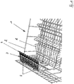
- Fig. 1 can be seen in a schematic perspective view of a known from the prior art dish rack 1 for a dishwashing machine not shown in the figures.
- the crockery basket 1 is formed from a wire mesh made of a plastic-coated wire 2 and serves in the intended use case of receiving items to be cleaned.
- the crockery basket 1 has for this purpose on appropriate recordings in the form of spikes, loops and the like.
- the crockery basket 1 further has a cup support 3. This is arranged by means of two hinge brackets 4 pivotally mounted on a provided by the crockery basket 1 side wall.
- the representation after Fig. 1 lets the cup support 3 in folded down position recognize, in which a recording of celeteiligem items to be washed, in particular cups is possible. In its non-use position, the cup support 3 is folded counterclockwise upwards.
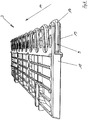
- the cup support 3 provides, as the following FIGS. 2 to 7 can be seen in each case, a lattice structure 5 formed from longitudinal struts 6 and cross struts 7 ready.
- This grid structure 5 carries in the intended use case of the cup support 3 recorded items.
- For articulated arrangement of the cup support 3 on the dish rack 1 serve provided by the grid structure 5 hinge axes 8, which engage in the final assembled state in the dish rack side hinge brackets 4.
- the cup support 3 has a holder 9 according to the invention, wherein the FIGS. 2 to 4 a first embodiment and the FIGS. 5 to 7 relate to a second embodiment.
- the embodiments differ only in the extension of the cup support 3 and thus also the holder 9 provided thereof in the longitudinal direction 10.
- the cup support 3 according to the second embodiment is shorter than the cup support 3 according to the first embodiment. Otherwise, the two embodiments identical, so that the same reference numerals identify the same components.
- the holder 9 is formed on the edge side of the pocket support 3, specifically along the longitudinal axis opposite the hinge axes 8.
- the holder 9 serves to receive stems 12, in particular long-stemmed stemmed glasses 13, as shown schematically in, for example, FIG Fig. 10 is indicated.
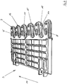
- To handle receiving the holder 9 has recesses 11, wherein a recess 11 for receiving a respective stem 12 is used.
- each recess 11 for receiving a respective stem 12 in the holder longitudinal direction 10 are arranged one behind the other.
- each recess 11 is equipped in each case with a clamping member 15 in the illustrated embodiment.
- Each clamping member 15 provides a terminal receptacle 16, in which a stem 12 of a stem glass 13 is inserted in the intended use case, as can be seen in particular from the illustration Fig. 10 results.
- the clamping parts 15 are provided by an integrally formed clamping part 17.
- This clamping part 17 is made of a resilient material, such as silicone.
- the grid structure 5 of the cup support 3 and the clamping part 17 are made of two different materials.
- the cup support 3 has a base body 18 and a mounting rail 19.
- the clamping part 17 is disposed between the base body 18 and the mounting rail 19.
- the base body 18 has moun- ting bar side connection pins 20 which provide latching tongues 21, which in the final assembled state engage in opening 22 provided by the mounting strip 19.
- the connecting bolts 20 in the final mounted state in the clamping sub-strip 17 extend through correspondingly formed passage openings 29.
- each has a clamping member 15 of the clamping part 17 via two legs, namely a first leg 25 and a second leg 26.
- the two legs 25 and 26 of a clamping member 15 form the provided by this clamping member 15 terminal receptacle 16 between them.
- Fig. 8 can be seen, due to the integral nature of the clamping sub-strip 17 and adjacent legs 25 and 26 adjacent clamping members 15 integrally formed, so that a total of a common tongue portion 27 results.
- This tongue part 27 provides the already described above through hole 29, through which engages in the final assembled state of the cup support 3 of the respective associated connecting pin 20. It is, as in particular the representation after Fig. 10 can recognize, each tongue portion 27 formed axially symmetrical, and the recess 29 is located on the axis of symmetry axis. Thus, in the final assembled state, a pivot point 31 defined by the connecting bolt 20 engaging through the respective passage opening 29 results.
- Each tongue part 27 furthermore has a recess 30 which, in the exemplary embodiment shown, is likewise axially symmetrical.
- the stem 13 is to introduce with its stem 12 in the direction of arrow 32 in the terminal 16 provided by the clamping member 16. Since the inlet opening of the clamping receptacle 16 is dimensioned narrower than the diameter of the stem 12, as a result of the insertion of the stem 12, an evasive movement of the associated legs 25 and 26 of the clamping part 5 occurs. This evasive movement arises as a rotational movement corresponding to the arrows 33 and 34th dar.
- each legannodem tongue portion 27 is a recess 30, in which the respectively associated leg 25 and 26 in a twisting movement in the direction of the arrows 33rd or 34 can immigrate.
- the material of the clamping sub-strip 17 that is compressed in this respect when inserting a handle 12 gives way to the recesses 30 provided by the tongue parts 27.
- both the base body 18 and the mounting rail 19 have correspondingly formed windows 35.
- the one-piece design of the clamping part strip 17 allows a simplified assembly. A Klemmteilmontage per recess 11 is avoided, because is equipped with a proper assembly of the cup support 3 with a clamping part 17 each of the holder 9 provided recess 11 with a corresponding clamping member 15.
- the terminal block 17 is mounted in spite of their integral parts per clamping member 15 relatively movable to the cup support 3. Stem jars 13 can be soft picked up and held securely in the intended use case. The resulting in a movement of the dish rack 1 shocks are attenuated by the clamping part 17 bar. In addition, it is ensured by the clamping holder that recorded by the holder 9 items to be kept away from further recorded by the dish rack 1 items to be washed.
- each clamping member 15 provided legs 25 and 26 also requires that over an entire insertion of a glass 13 an equal force on the stem 12 of the glass 13 acts. This is gentle on materials, in particular for the elastic material of the clamping part 17, so that a long service life is reached.
Landscapes
- Washing And Drying Of Tableware (AREA)
Applications Claiming Priority (3)
| Application Number | Priority Date | Filing Date | Title |
|---|---|---|---|
| DE102015112783.0A DE102015112783A1 (de) | 2015-08-04 | 2015-08-04 | Halter für einen Geschirrkorb |
| DE102015112787.3A DE102015112787A1 (de) | 2015-08-04 | 2015-08-04 | Halter für einen Geschirrkorb |
| EP16177096.1A EP3127464B1 (fr) | 2015-08-04 | 2016-06-30 | Fixation pour panier a vaisselle |
Related Parent Applications (2)
| Application Number | Title | Priority Date | Filing Date |
|---|---|---|---|
| EP16177096.1A Division-Into EP3127464B1 (fr) | 2015-08-04 | 2016-06-30 | Fixation pour panier a vaisselle |
| EP16177096.1A Division EP3127464B1 (fr) | 2015-08-04 | 2016-06-30 | Fixation pour panier a vaisselle |
Publications (1)
| Publication Number | Publication Date |
|---|---|
| EP3326509A1 true EP3326509A1 (fr) | 2018-05-30 |
Family
ID=56296642
Family Applications (2)
| Application Number | Title | Priority Date | Filing Date |
|---|---|---|---|
| EP17206938.7A Withdrawn EP3326509A1 (fr) | 2015-08-04 | 2016-06-30 | Support de fixation pour panier à vaisselle |
| EP16177096.1A Active EP3127464B1 (fr) | 2015-08-04 | 2016-06-30 | Fixation pour panier a vaisselle |
Family Applications After (1)
| Application Number | Title | Priority Date | Filing Date |
|---|---|---|---|
| EP16177096.1A Active EP3127464B1 (fr) | 2015-08-04 | 2016-06-30 | Fixation pour panier a vaisselle |
Country Status (1)
| Country | Link |
|---|---|
| EP (2) | EP3326509A1 (fr) |
Families Citing this family (6)
| Publication number | Priority date | Publication date | Assignee | Title |
|---|---|---|---|---|
| EP3357397B1 (fr) * | 2017-02-01 | 2022-03-09 | Miele & Cie. KG | Support de tasses |
| EP3357398B1 (fr) * | 2017-02-02 | 2020-03-11 | Miele & Cie. KG | Support de tasses avec un dispositif de serrage |
| CN107233058B (zh) * | 2017-06-26 | 2019-06-04 | 张心禾 | 商业用玻璃杯清洗装置 |
| CN109363609B (zh) * | 2018-12-26 | 2024-09-10 | 湖北科技学院 | 一种洗碗机中的碗碟夹持装置 |
| CN111802999A (zh) * | 2019-04-11 | 2020-10-23 | 青岛海尔洗碗机有限公司 | 一种洗碗机搁架及洗碗机 |
| US11730339B2 (en) * | 2020-12-07 | 2023-08-22 | Haier Us Appliance Solutions, Inc. | Article holder assembly for a dishwasher appliance |
Citations (4)
| Publication number | Priority date | Publication date | Assignee | Title |
|---|---|---|---|---|
| DE9216330U1 (de) * | 1992-12-01 | 1994-04-07 | Licentia Patent-Verwaltungs-Gmbh, 60596 Frankfurt | Oberkorb für Haushalt-Geschirrspülmaschinen |
| WO1998047542A1 (fr) * | 1997-04-22 | 1998-10-29 | Case Medical, Inc. | Support d'instrument avec organes elastiques de blocage a utiliser avec plateau sterilisable |
| DE29711822U1 (de) * | 1997-07-05 | 1998-10-29 | AEG Hausgeräte GmbH, 90429 Nürnberg | Geschirrspülmaschine mit einem Geschirrkorb |
| EP1424035A1 (fr) * | 2002-11-29 | 2004-06-02 | Electrolux Home Products Corporation N.V. | Support pour vaisselle placé dans un panier de lave-vaisselle |
-
2016
- 2016-06-30 EP EP17206938.7A patent/EP3326509A1/fr not_active Withdrawn
- 2016-06-30 EP EP16177096.1A patent/EP3127464B1/fr active Active
Patent Citations (4)
| Publication number | Priority date | Publication date | Assignee | Title |
|---|---|---|---|---|
| DE9216330U1 (de) * | 1992-12-01 | 1994-04-07 | Licentia Patent-Verwaltungs-Gmbh, 60596 Frankfurt | Oberkorb für Haushalt-Geschirrspülmaschinen |
| WO1998047542A1 (fr) * | 1997-04-22 | 1998-10-29 | Case Medical, Inc. | Support d'instrument avec organes elastiques de blocage a utiliser avec plateau sterilisable |
| DE29711822U1 (de) * | 1997-07-05 | 1998-10-29 | AEG Hausgeräte GmbH, 90429 Nürnberg | Geschirrspülmaschine mit einem Geschirrkorb |
| EP1424035A1 (fr) * | 2002-11-29 | 2004-06-02 | Electrolux Home Products Corporation N.V. | Support pour vaisselle placé dans un panier de lave-vaisselle |
Also Published As
| Publication number | Publication date |
|---|---|
| EP3127464B1 (fr) | 2018-01-31 |
| EP3127464A1 (fr) | 2017-02-08 |
Similar Documents
| Publication | Publication Date | Title |
|---|---|---|
| EP3127464B1 (fr) | Fixation pour panier a vaisselle | |
| EP4108155B1 (fr) | Support pour un panier de rinçage | |
| EP3357398B1 (fr) | Support de tasses avec un dispositif de serrage | |
| EP1683465B1 (fr) | Panier pour lave-vaisselle | |
| DE102015112783A1 (de) | Halter für einen Geschirrkorb | |
| DE102013100138A1 (de) | Besteckschublade für eine Geschirrspülmaschine | |
| EP2353488A1 (fr) | Utilisation pour un panier d'un lave-vaisselle | |
| EP1993427A1 (fr) | Insert de panier pour lave-vaisselle | |
| DE102013211564A1 (de) | Glashalter für einen Geschirrkorb einer Geschirrspülmaschine, Geschirrkorb für eine Geschirrspülmaschine und Geschirrspülmaschine | |
| DE102014226808A1 (de) | Haltevorrichtung, Spülgutaufnahme und wasserführendes Haushaltsgerät | |
| DE102013103707A1 (de) | Besteckkorb | |
| DE3407503C2 (fr) | ||
| DE102013110531A1 (de) | Gläserhalter für Geschirrspülmaschinen | |
| EP3357397B1 (fr) | Support de tasses | |
| DE102015112787A1 (de) | Halter für einen Geschirrkorb | |
| EP1649798B1 (fr) | Panier de lave-vaisselle, insert de panier et éléments de fixation | |
| DE102024114840A1 (de) | Spülgutauflage, insbesondere Tassenauflage | |
| DE29720069U1 (de) | Halterung für einen Geschirrkorb | |
| DE29816622U1 (de) | Gestell zur Aufnahme von langröhrigen Gläsern in Geschirrspülern | |
| CH690488A5 (de) | Höhenverstellbare Korbeinheit für Wasch- und Reinigungsgeräte. | |
| EP3175763A1 (fr) | Panier à vaisselle, notamment tiroir à couverts | |
| WO2020038787A1 (fr) | Élément rapporté de support de verre | |
| DE102018212543B4 (de) | Magnethaltevorrichtung, Spülgutaufnahme und Haushaltsgeschirrspülmaschine | |
| DE202013101621U1 (de) | Endpunktlager von Querlatten einer Matratzenunterfederung | |
| BE1031672B1 (de) | Spülgutauflage, insbesondere Tassenauflage |
Legal Events
| Date | Code | Title | Description |
|---|---|---|---|
| PUAI | Public reference made under article 153(3) epc to a published international application that has entered the european phase |
Free format text: ORIGINAL CODE: 0009012 |
|
| STAA | Information on the status of an ep patent application or granted ep patent |
Free format text: STATUS: THE APPLICATION HAS BEEN PUBLISHED |
|
| AC | Divisional application: reference to earlier application |
Ref document number: 3127464 Country of ref document: EP Kind code of ref document: P |
|
| AK | Designated contracting states |
Kind code of ref document: A1 Designated state(s): AL AT BE BG CH CY CZ DE DK EE ES FI FR GB GR HR HU IE IS IT LI LT LU LV MC MK MT NL NO PL PT RO RS SE SI SK SM TR |
|
| RIN1 | Information on inventor provided before grant (corrected) |
Inventor name: ZILLICH, GUIDO Inventor name: SGURSKI, EUGEN Inventor name: RENZ, EUGEN Inventor name: SCHUETTE, THORSTEN |
|
| STAA | Information on the status of an ep patent application or granted ep patent |
Free format text: STATUS: REQUEST FOR EXAMINATION WAS MADE |
|
| 17P | Request for examination filed |
Effective date: 20181025 |
|
| RBV | Designated contracting states (corrected) |
Designated state(s): AL AT BE BG CH CY CZ DE DK EE ES FI FR GB GR HR HU IE IS IT LI LT LU LV MC MK MT NL NO PL PT RO RS SE SI SK SM TR |
|
| STAA | Information on the status of an ep patent application or granted ep patent |
Free format text: STATUS: EXAMINATION IS IN PROGRESS |
|
| 17Q | First examination report despatched |
Effective date: 20210803 |
|
| STAA | Information on the status of an ep patent application or granted ep patent |
Free format text: STATUS: THE APPLICATION HAS BEEN WITHDRAWN |
|
| 18W | Application withdrawn |
Effective date: 20211119 |