EP3326603B1 - Système de commande hybride à base d'évaluation d'intention d'utilisateur pour système intelligent d'aide à la marche - Google Patents
Système de commande hybride à base d'évaluation d'intention d'utilisateur pour système intelligent d'aide à la marche Download PDFInfo
- Publication number
- EP3326603B1 EP3326603B1 EP16002500.3A EP16002500A EP3326603B1 EP 3326603 B1 EP3326603 B1 EP 3326603B1 EP 16002500 A EP16002500 A EP 16002500A EP 3326603 B1 EP3326603 B1 EP 3326603B1
- Authority
- EP
- European Patent Office
- Prior art keywords
- user
- platform
- sub
- control
- motion
- Prior art date
- Legal status (The legal status is an assumption and is not a legal conclusion. Google has not performed a legal analysis and makes no representation as to the accuracy of the status listed.)
- Active
Links
Images

Classifications
-
- A—HUMAN NECESSITIES
- A61—MEDICAL OR VETERINARY SCIENCE; HYGIENE
- A61H—PHYSICAL THERAPY APPARATUS, e.g. DEVICES FOR LOCATING OR STIMULATING REFLEX POINTS IN THE BODY; ARTIFICIAL RESPIRATION; MASSAGE; BATHING DEVICES FOR SPECIAL THERAPEUTIC OR HYGIENIC PURPOSES OR SPECIFIC PARTS OF THE BODY
- A61H3/00—Appliances for aiding patients or disabled persons to walk about
- A61H3/008—Appliances for aiding patients or disabled persons to walk about using suspension devices for supporting the body in an upright walking or standing position, e.g. harnesses
-
- A—HUMAN NECESSITIES
- A61—MEDICAL OR VETERINARY SCIENCE; HYGIENE
- A61H—PHYSICAL THERAPY APPARATUS, e.g. DEVICES FOR LOCATING OR STIMULATING REFLEX POINTS IN THE BODY; ARTIFICIAL RESPIRATION; MASSAGE; BATHING DEVICES FOR SPECIAL THERAPEUTIC OR HYGIENIC PURPOSES OR SPECIFIC PARTS OF THE BODY
- A61H3/00—Appliances for aiding patients or disabled persons to walk about
- A61H3/04—Wheeled walking aids for patients or disabled persons
-
- A—HUMAN NECESSITIES
- A61—MEDICAL OR VETERINARY SCIENCE; HYGIENE
- A61H—PHYSICAL THERAPY APPARATUS, e.g. DEVICES FOR LOCATING OR STIMULATING REFLEX POINTS IN THE BODY; ARTIFICIAL RESPIRATION; MASSAGE; BATHING DEVICES FOR SPECIAL THERAPEUTIC OR HYGIENIC PURPOSES OR SPECIFIC PARTS OF THE BODY
- A61H3/00—Appliances for aiding patients or disabled persons to walk about
- A61H2003/007—Appliances for aiding patients or disabled persons to walk about secured to the patient, e.g. with belts
-
- A—HUMAN NECESSITIES
- A61—MEDICAL OR VETERINARY SCIENCE; HYGIENE
- A61H—PHYSICAL THERAPY APPARATUS, e.g. DEVICES FOR LOCATING OR STIMULATING REFLEX POINTS IN THE BODY; ARTIFICIAL RESPIRATION; MASSAGE; BATHING DEVICES FOR SPECIAL THERAPEUTIC OR HYGIENIC PURPOSES OR SPECIFIC PARTS OF THE BODY
- A61H3/00—Appliances for aiding patients or disabled persons to walk about
- A61H3/04—Wheeled walking aids for patients or disabled persons
- A61H2003/043—Wheeled walking aids for patients or disabled persons with a drive mechanism
-
- A—HUMAN NECESSITIES
- A61—MEDICAL OR VETERINARY SCIENCE; HYGIENE
- A61H—PHYSICAL THERAPY APPARATUS, e.g. DEVICES FOR LOCATING OR STIMULATING REFLEX POINTS IN THE BODY; ARTIFICIAL RESPIRATION; MASSAGE; BATHING DEVICES FOR SPECIAL THERAPEUTIC OR HYGIENIC PURPOSES OR SPECIFIC PARTS OF THE BODY
- A61H2201/00—Characteristics of apparatus not provided for in the preceding codes
- A61H2201/16—Physical interface with patient
- A61H2201/1602—Physical interface with patient kind of interface, e.g. head rest, knee support or lumbar support
- A61H2201/1628—Pelvis
- A61H2201/163—Pelvis holding means therefor
-
- A—HUMAN NECESSITIES
- A61—MEDICAL OR VETERINARY SCIENCE; HYGIENE
- A61H—PHYSICAL THERAPY APPARATUS, e.g. DEVICES FOR LOCATING OR STIMULATING REFLEX POINTS IN THE BODY; ARTIFICIAL RESPIRATION; MASSAGE; BATHING DEVICES FOR SPECIAL THERAPEUTIC OR HYGIENIC PURPOSES OR SPECIFIC PARTS OF THE BODY
- A61H2201/00—Characteristics of apparatus not provided for in the preceding codes
- A61H2201/16—Physical interface with patient
- A61H2201/1602—Physical interface with patient kind of interface, e.g. head rest, knee support or lumbar support
- A61H2201/165—Wearable interfaces
- A61H2201/1652—Harness
-
- A—HUMAN NECESSITIES
- A61—MEDICAL OR VETERINARY SCIENCE; HYGIENE
- A61H—PHYSICAL THERAPY APPARATUS, e.g. DEVICES FOR LOCATING OR STIMULATING REFLEX POINTS IN THE BODY; ARTIFICIAL RESPIRATION; MASSAGE; BATHING DEVICES FOR SPECIAL THERAPEUTIC OR HYGIENIC PURPOSES OR SPECIFIC PARTS OF THE BODY
- A61H2201/00—Characteristics of apparatus not provided for in the preceding codes
- A61H2201/16—Physical interface with patient
- A61H2201/1657—Movement of interface, i.e. force application means
- A61H2201/1676—Pivoting
-
- A—HUMAN NECESSITIES
- A61—MEDICAL OR VETERINARY SCIENCE; HYGIENE
- A61H—PHYSICAL THERAPY APPARATUS, e.g. DEVICES FOR LOCATING OR STIMULATING REFLEX POINTS IN THE BODY; ARTIFICIAL RESPIRATION; MASSAGE; BATHING DEVICES FOR SPECIAL THERAPEUTIC OR HYGIENIC PURPOSES OR SPECIFIC PARTS OF THE BODY
- A61H2201/00—Characteristics of apparatus not provided for in the preceding codes
- A61H2201/50—Control means thereof
- A61H2201/5007—Control means thereof computer controlled
-
- A—HUMAN NECESSITIES
- A61—MEDICAL OR VETERINARY SCIENCE; HYGIENE
- A61H—PHYSICAL THERAPY APPARATUS, e.g. DEVICES FOR LOCATING OR STIMULATING REFLEX POINTS IN THE BODY; ARTIFICIAL RESPIRATION; MASSAGE; BATHING DEVICES FOR SPECIAL THERAPEUTIC OR HYGIENIC PURPOSES OR SPECIFIC PARTS OF THE BODY
- A61H2201/00—Characteristics of apparatus not provided for in the preceding codes
- A61H2201/50—Control means thereof
- A61H2201/5023—Interfaces to the user
-
- A—HUMAN NECESSITIES
- A61—MEDICAL OR VETERINARY SCIENCE; HYGIENE
- A61H—PHYSICAL THERAPY APPARATUS, e.g. DEVICES FOR LOCATING OR STIMULATING REFLEX POINTS IN THE BODY; ARTIFICIAL RESPIRATION; MASSAGE; BATHING DEVICES FOR SPECIAL THERAPEUTIC OR HYGIENIC PURPOSES OR SPECIFIC PARTS OF THE BODY
- A61H2201/00—Characteristics of apparatus not provided for in the preceding codes
- A61H2201/50—Control means thereof
- A61H2201/5023—Interfaces to the user
- A61H2201/5038—Interfaces to the user freely programmable by the user
-
- A—HUMAN NECESSITIES
- A61—MEDICAL OR VETERINARY SCIENCE; HYGIENE
- A61H—PHYSICAL THERAPY APPARATUS, e.g. DEVICES FOR LOCATING OR STIMULATING REFLEX POINTS IN THE BODY; ARTIFICIAL RESPIRATION; MASSAGE; BATHING DEVICES FOR SPECIAL THERAPEUTIC OR HYGIENIC PURPOSES OR SPECIFIC PARTS OF THE BODY
- A61H2201/00—Characteristics of apparatus not provided for in the preceding codes
- A61H2201/50—Control means thereof
- A61H2201/5058—Sensors or detectors
- A61H2201/5069—Angle sensors
Definitions
- Walk rehabilitation is a multi-step process that is aimed to return the freedom of motion to the patient. It starts with intense therapy of the muscular system and proceeds with the supervised static and dynamic balance training.
- the dynamic balance training is typically performed in presence of at least two expert therapist that manually assist the subject to walk and maintain the balance at the same time.
- Several technical solutions have been proposed to relieve the therapists from this physically intensive engagement.
- Document DE102008029564 A1 discloses a device for muscle training. It has a carrier platform that has a mobile module attached at a driving chassis by the driving device. At one end of the retaining arm a supporting mechanism is arranged to support the user, whereas the other end of the retaining arm is connected to the carrier platform by means of two pivotal connections arranged such that the pivot axes are arranged perpendicular to each other.
- the retaining arm can thus be inclined in forward/backward direction as well as in left/right direction.
- the device generates control signals based on a deflection of the retaining arm from its reference position to control the speed of the carrier platform.
- This invention relates to the Gait Balance Trainer device, a therapist controlled motor driven device that is used for balance training during walking.
- Two independent motorized wheels on each side of the platform's base frame are used for powered actuation of the device in terms of linear (forward / backward) and rotational movement, allowing the device to move in straight lines or turn at different turning radii.
- the patient that uses the device is embraced around pelvis with the appropriate harness, which is coupled to two vertical rods/struts. These struts are mounted to the base frame of the device using adjustable helical springs, which allow the therapist to select the amount of physical support of the patient during training by changing the spring's compliance.
- the framework ensures natural pelvic movement and fail-safe training conditions for the patient.
- the patient is given ability to lean forward, backward and sideways and/or rotate in the pelvic region. This movement provokes the helical springs to bend from vertical position, producing a stabilizing force on the patient.
- the therapist controls the device during training using a remote control, manually setting the speed at which the device moves forward/backwards and rotates.
- a control system was therefore designed to relieve the therapist of the constant and direct control of the platform and allow the platform to actively follow the patient's motion.
- the invention is in relation to the design, inclusion and implementation of the control system for walking assist and rehabilitation platform.
- the presented control system produces the control signals for the platform actuators by joining the information on relative user position in regards to the platform, forces the user is exerting to platform, current operating mode of the system, control strategy, platform's position in the environment, position of the obstacles in the environment and/or therapist commands.
- the aim of the control system is to relieve the therapist of the constant and direct control of the platform and allow a controlled partial or full handover of the control of the platform to a user (a patient that is using the device).
- the relative user's position in regards to the platform is determined by observing the deflection of the user-supporting struts.
- the struts deflect out of phase with the rotation of the user's pelvis and in-phase with forward/backward or lateral motion.
- the deflection angles of the struts can therefore be decomposed into three separate states, describing user's relative rotation around the vertical axis and relative position with two planar coordinates.
- the measured user's position is then converted into the estimate of the user's intentions of motion, which is then used to construct the control signals for the platform drivetrain.
- the central control sub-system receives input from the user-intention-determination sub-system, user interface sub-system, therapist user-interface sub-system and optionally from navigation sub-system, which determines the position of the platform and potential obstacles in the environment.
- Final commands to the system's drivetrain are generated by combining all those inputs according to the selected operational mode (e.g. full user control, full therapist control, adaptive user control etc.).
- the concept of the invention is a functional upgrade in terms of a central control system of (but not limited to) an existing rehabilitation platform Gait Balance Trainer (Patent application US2014/0179493 A1 ) for the purpose of increasing the platform's autonomy either by executing a controlled handover to a user, therapist, internal navigation system or a combination of those.
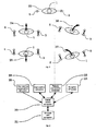
- the claimed control system is organized into logical groups or sub-systems that are illustrated in Fig. 4 .
- the Central control sub-system 30 functions as a hub for all control-related information and does central processing of the data. It is interconnected with other sub-systems, the User intention determination sub-system 29, that handles the determination and interpretation of user intentions, as will be described later on, the User interface sub-system 28, which is designed for communication with the user of the device 1, the Therapist user-interface sub-system 32, which is designed for communication with the therapist, that is in charge of the rehabilitation process, optional Navigation sub-system 33, that is determining the relation between the platform, illustrated in Fig. 1 , and the environment, while the Drivetrain unit sub-system 31 controls the drivetrain units 8 and 9.
- the platform, that the claimed control system is applied to, is illustrated in Fig. 1 .
- the platform, that can move in world coordinate system 14, consists of the base frame 13 with two drivetrain units 8 and 9, that actuate two wheels in contact with the ground, data processing unit 12, two or more un-actuated wheels 10 and 11, attachment points 6 and 7 for the user-supporting vertical struts 3 and 5, user attachment harness 4 and horizontal strut 2.
- User 1 is strapped to the platform with the help of the attachment harness 4 that together with horizontal strut 2 and vertical struts 3 and 5 allows a freedom of motion in regards to the platform's base frame 13, while providing the support in the case of the user losing balance and thus preventing the user 1 from falling.
- the elastic connecting joints 6, 7 between the vertical struts 3, 5 and base frame 13 can have adjustable stiffness, that affects the relation between the exerted force of the user 1 to the harness 4 and the vertical struts 3, 5 deflection from the vertical position, as illustrated in Fig. 2 .
- the vertical struts 3, 5 are deflected for a certain angle 16 from the neutral position 17 that is proportional to the force.
- Side motion of the user deflects the vertical struts 3, 5 from neutral vertical position 20 as illustrated by the angle 19 and the rotational motion of the user 1 in the pelvic area around the vertical axis (Patent application WO2014081400 A2 ) deflects the vertical struts 3, 5 from the vertical position in the opposite directions.
- the deflection of the struts is measured as a difference in orientation of the vertical-struts-fixed coordinate system 15, 18 in regards to the base-frame-fixed coordinate system 21, 22 or/and the world coordinate system 14.
- the deflection angles 16, 19 of the vertical struts are proportional to the forces exerted by the user 1 in regards to the platform base frame 13.
- both left 5 and right 3 vertical struts are deflected in the backwards direction, this is interpreted as user intention of accelerating in the backward direction, as depicted in 25.
- the situation with left strut 5 being deflected forwards and right strut 3 being deflected backwards is interpreted as user intention of turning in the clock-wise direction if seen from the top, as depicted in 26.
- the opposite situation with left strut 5 being deflected backwards and the right strut 3 being deflected forwards is interpreted as user intention of turning in anti-clock-wise direction, as depicted in 27.
- the main concept of the claimed control system invention lies in determining the user's intention of moving forward/backward and steering by using strut deflection angles (which is processed by the User intention determination sub-system 29), then producing the appropriate control signals in Central control sub-system 30 for the platform drivetrain (handled by the Drivetrain unit sub-system 31) to intuitively follow the user or control the platforms motion via other means (remote control via Therapist user-interface sub-system 32, full automatic navigation or semi-automatic navigation with the use of the Navigation sub-system 33 etc.).
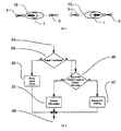
- the logic behind the control process that allows the user to control the platform is illustrated by the block diagram in Fig. 6 .
- the illustrated logic is evaluated periodically as a part of the control loop in the Central control sub-system 30. Evaluation of the control process is started at the entry point 34, where the signal, that corresponds to the quantified assessment of the user intention, defined as intended lateral and rotational motion, is compared with its deadband specification 35. If the absolute signal value is less than its specified deadband, the control signal value from previous iteration is decayed using the exponent function in order to obtain the effect of smooth transition between deadband and out-of-deadband situations.
- the direction of the signal (the assessment of the user-intended motion) is compared with the existing direction of platform's motion in block 39. Namely, if the user commands the motion that is in the opposite direction of the current motion, exponential braking step 40 is executed first to command the platform's motion to a smooth, but actively-executed stop, before accelerating in the requested direction.
- the exponential braking step 40 uses similar approach as the Decay signal values step 36 with the difference in the fact that the signal decay slope is controlled by the amplitude of the commanded signal. Therefore, bigger signal values result in more aggressive stopping motion, allowing anything from a controlled slow stop with small commanded signal values up to almost abrupt stop, as a result of large commanded signal.
- a PID controller 37 is used for controlling the motion of the platform while the direction of the commanded signal coincides with the direction of the current platform's motion.
Landscapes
- Health & Medical Sciences (AREA)
- Epidemiology (AREA)
- Pain & Pain Management (AREA)
- Physical Education & Sports Medicine (AREA)
- Rehabilitation Therapy (AREA)
- Life Sciences & Earth Sciences (AREA)
- Animal Behavior & Ethology (AREA)
- General Health & Medical Sciences (AREA)
- Public Health (AREA)
- Veterinary Medicine (AREA)
- Rehabilitation Tools (AREA)
Claims (5)
- Système d'aide à la marche comprenant :- une plate-forme comprenant en outre un châssis de base en forme de U (13) avec deux roues motorisées entraînées par des unités de transmission (8, 9) et avec au moins deux roues non entraînées (10, 11) qui permettent de déplacer la plate-forme à la fois linéairement et en rotation autour d'un axe vertical ;- un système de support à l'utilisateur comprenant en outre une paire de montants verticaux (3, 5) attachés au moyen de joints de liaison élastiques (6, 7) au châssis de base (13) de la plate-forme, un montant horizontal (2) qui interconnecte la paire de montants verticaux (3, 5) sur son extrémité supérieure, et un harnais d'utilisateur avec des sangles (4) attachées au montant horizontal (2) au moyen desquelles l'utilisateur est sanglé de manière sûre afin d'empêcher l'utilisateur de tomber, les joints de liaison élastiques (6, 7) étant formés de manière à permettre la flexion pivotante des montants (3, 5) à partir de la position verticale neutre (17) ; et- un système de commande ;caractérisé en ce que le système comprend en outre un dispositif pour mesurer les flexions des montants (3, 5) par rapport à la position verticale neutre (17), lesdites flexions étant proportionnelles aux forces exercées sur les montants par l'utilisateur (1),
le système de commande permettant à la plate-forme de suivre activement le mouvement prévu de l'utilisateur sur la base d'un signal reçu du dispositif, et le système de commande étant organisé en groupes logiques ou sous-systèmes comme suit :∘ un sous-système central de commande (30) faisant office de plaque tournante pour toutes les informations relatives à la commande et réalisant le traitement central des données ;∘ un sous-système de détermination des intentions de l'utilisateur (29) qui gère la détermination et l'interprétation des intentions de l'utilisateur,∘ un sous-système d'interface utilisateur (28) conçu pour la communication avec l'utilisateur (1) du système,∘ un sous-système d'interface utilisateur de thérapeute (32) conçu pour la communication avec le thérapeute qui est responsable du processus de réadaptation, et∘ un sous-système d'unité de transmission (31) commandant les unités de transmission (8, 9) ; ledit sous-système central de commande (30) étant interconnecté avec d'autres sous-systèmes mentionnés (29, 28, 32, 31), le sous-système de détermination des intentions de l'utilisateur (29) étant conçu pour commander le mouvement de la plate-forme comme suit :- lorsqu'il n'y a pas de flexion de la verticale gauche (5) et de la verticale droite (3), le système de commande maintient le mouvement de la plate-forme tel qu'il est,- lorsque les montants verticaux gauche (5) et droit (3) sont fléchis vers l'avant, le système de commande réagit en accélérant la plate-forme vers l'avant,- lorsque les montants verticaux gauche (5) et droit (3) sont fléchis vers l'arrière, le système de commande réagit en accélérant la plate-forme vers l'arrière,- lorsque le montant gauche (5) est fléchi vers l'avant et que le montant droit (3) est fléchi vers l'arrière, le système de commande réagit en tournant la plate-forme dans le sens horaire lorsqu'elle est vue du haut, et- lorsque le montant gauche (5) est fléchi vers l'arrière et que le montant droit (3) est fléchi vers l'avant, le système de commande réagit en tournant la plate-forme dans le sens anti-horaire lorsqu'elle est vue du haut. - Système d'aide à la marche selon la revendication 1, caractérisé en ce que le système de commande est organisé en un groupe logique ou sous-système supplémentaire, à savoir un sous-système de navigation (33) qui détermine la relation entre la plate-forme et l'environnement ; ledit sous-système central de commande (30) étant également interconnecté avec le sous-système de navigation (33).
- Système d'aide à la marche selon la revendication 1 ou 2, caractérisé en ce que le sous-système d'interface utilisateur (28) est utilisé pour communiquer à l'utilisateur l'état du système, et éventuellement pour permettre à l'utilisateur de modifier la stratégie de commande ou pour commander les paramètres du système.
- Système d'aide à la marche selon l'une quelconque des revendications 1 à 3, caractérisé en ce que le sous-système d'interface utilisateur de thérapeute (32) est utilisé pour communiquer au thérapeute l'état du système, l'évaluation des capacités de marche de l'utilisateur, et pour permettre au thérapeute de modifier la stratégie de commande ou de commander les paramètres du système.
- Procédure de commande du système selon l'une quelconque des revendications précédentes, comprenant les étapes suivantes :a) comparaison (35) de l'évaluation quantifiée de l'intention de l'utilisateur sous forme d'un signal (34) avec une bande morte ;
si la valeur absolue dudit signal est inférieure à la valeur spécifiée de la zone morte, la procédure continue avec l'étape e), sinon la procédure continue avec l'étape b),b) comparaison (39) de la direction du signal d'entrée de l'étape a) avec la direction existante du mouvement de la plate-forme ;
si les directions sont opposées, la procédure continue avec l'étape c), sinon la procédure continue avec l'étape d)c) freinage exponentiel (40) pour amener le mouvement de la plate-forme à un arrêt en douceur mais activement exécuté, la pente de décroissance du signal étant contrôlée par l'amplitude du signal commandé, puis la procédure est terminée (38) ;d) commande (37) du mouvement de la plate-forme au moyen d'un régulateur PID, puis la procédure est terminée (38) ;e) décroissance (36) des valeurs de signal, puis la procédure est terminée (38).
Priority Applications (1)
| Application Number | Priority Date | Filing Date | Title |
|---|---|---|---|
| EP16002500.3A EP3326603B1 (fr) | 2016-11-24 | 2016-11-24 | Système de commande hybride à base d'évaluation d'intention d'utilisateur pour système intelligent d'aide à la marche |
Applications Claiming Priority (1)
| Application Number | Priority Date | Filing Date | Title |
|---|---|---|---|
| EP16002500.3A EP3326603B1 (fr) | 2016-11-24 | 2016-11-24 | Système de commande hybride à base d'évaluation d'intention d'utilisateur pour système intelligent d'aide à la marche |
Publications (3)
| Publication Number | Publication Date |
|---|---|
| EP3326603A1 EP3326603A1 (fr) | 2018-05-30 |
| EP3326603A8 EP3326603A8 (fr) | 2018-12-26 |
| EP3326603B1 true EP3326603B1 (fr) | 2020-02-12 |
Family
ID=57421603
Family Applications (1)
| Application Number | Title | Priority Date | Filing Date |
|---|---|---|---|
| EP16002500.3A Active EP3326603B1 (fr) | 2016-11-24 | 2016-11-24 | Système de commande hybride à base d'évaluation d'intention d'utilisateur pour système intelligent d'aide à la marche |
Country Status (1)
| Country | Link |
|---|---|
| EP (1) | EP3326603B1 (fr) |
Family Cites Families (6)
| Publication number | Priority date | Publication date | Assignee | Title |
|---|---|---|---|---|
| DE102008029564B4 (de) * | 2008-06-21 | 2015-12-24 | medica - Medizintechnik GmbH | Mobile Trainings-Vorrichtung zum Aufbau der Muskulatur des Gehapparates |
| DE112011105572A5 (de) | 2011-08-31 | 2014-06-12 | medica - Medizintechnik GmbH | Therapeutischer Gehtrainer |
| US9907721B2 (en) * | 2012-03-29 | 2018-03-06 | GaitTronics inc. | Control system and device for patient assist |
| EP2922517B1 (fr) | 2012-11-21 | 2018-10-10 | Univerzitetni Rehabilitacijski Institut Republike Slovenije SOCA | Appareil d'entraînement de man uvres d'équilibre et de rotation dynamiques pendant la marche |
| JP2015047944A (ja) * | 2013-08-30 | 2015-03-16 | 船井電機株式会社 | 手動推進車両 |
| EP3102171A4 (fr) * | 2014-02-05 | 2018-03-28 | President and Fellows of Harvard College | Systèmes, procédés et dispositifs d'aide à la marche pour des tout-petits présentant un retard de développement |
-
2016
- 2016-11-24 EP EP16002500.3A patent/EP3326603B1/fr active Active
Non-Patent Citations (1)
| Title |
|---|
| None * |
Also Published As
| Publication number | Publication date |
|---|---|
| EP3326603A1 (fr) | 2018-05-30 |
| EP3326603A8 (fr) | 2018-12-26 |
Similar Documents
| Publication | Publication Date | Title |
|---|---|---|
| JP7174705B2 (ja) | 外骨格を動かすための方法 | |
| Colgate et al. | Cobots: Robots for collaboration with human operators | |
| CN100344419C (zh) | 双腿步行式人形机器人 | |
| CN104155976B (zh) | 自主式球轮移动机器人及其控制方法 | |
| KR101549817B1 (ko) | 로봇의 보행 제어장치 및 그 방법 | |
| US20130218345A1 (en) | Walking robot and control method thereof | |
| US20110301756A1 (en) | Control device for legged mobile robot | |
| WO2010122705A1 (fr) | Dispositif et procédé de commande de robot, et robot comportant des jambes | |
| US8972058B2 (en) | Wearable robot and control method thereof | |
| WO2003090978A1 (fr) | Dispositif de commande d'un robot mobile dote de jambes | |
| CN113568422B (zh) | 基于模型预测控制优化强化学习的四足机器人控制方法 | |
| JP5633166B2 (ja) | ロボット、及びその制御方法 | |
| US10046796B2 (en) | Travelling apparatus, control method of travelling apparatus, and control program of travelling apparatus | |
| Yi et al. | Online learning of a full body push recovery controller for omnidirectional walking | |
| Heinzmann et al. | A safe-control paradigm for human–robot interaction | |
| WO2023161228A1 (fr) | Procédés d'entraînement d'un réseau de neurones et d'utilisation dudit réseau de neurones pour stabiliser un robot bipède | |
| Ding et al. | Walking stabilization control for humanoid robots on unknown slope based on walking sequences adjustment | |
| Fontanelli et al. | Unicycle steering by brakes: a passive guidance support for an assistive cart | |
| EP3326603B1 (fr) | Système de commande hybride à base d'évaluation d'intention d'utilisateur pour système intelligent d'aide à la marche | |
| Bošnak et al. | Embedded control system for smart walking assistance device | |
| KR101698109B1 (ko) | 착용형 외골격 로봇의 자세 제어 장치 및 그 방법 | |
| Chen et al. | Enabling Shared-Control for A Riding Ballbot System | |
| CN115501089A (zh) | 一种助行设备及其控制方法 | |
| GB2538712A (en) | Hybrid user-intention-assessment based control system for a smart walking assist system | |
| Teodorescu et al. | A stochastic control strategy for safely driving a powered wheelchair |
Legal Events
| Date | Code | Title | Description |
|---|---|---|---|
| PUAI | Public reference made under article 153(3) epc to a published international application that has entered the european phase |
Free format text: ORIGINAL CODE: 0009012 |
|
| STAA | Information on the status of an ep patent application or granted ep patent |
Free format text: STATUS: THE APPLICATION HAS BEEN PUBLISHED |
|
| AK | Designated contracting states |
Kind code of ref document: A1 Designated state(s): AL AT BE BG CH CY CZ DE DK EE ES FI FR GB GR HR HU IE IS IT LI LT LU LV MC MK MT NL NO PL PT RO RS SE SI SK SM TR |
|
| AX | Request for extension of the european patent |
Extension state: BA ME |
|
| STAA | Information on the status of an ep patent application or granted ep patent |
Free format text: STATUS: REQUEST FOR EXAMINATION WAS MADE |
|
| 17P | Request for examination filed |
Effective date: 20181016 |
|
| RBV | Designated contracting states (corrected) |
Designated state(s): AL AT BE BG CH CY CZ DE DK EE ES FI FR GB GR HR HU IE IS IT LI LT LU LV MC MK MT NL NO PL PT RO RS SE SI SK SM TR |
|
| RAP1 | Party data changed (applicant data changed or rights of an application transferred) |
Owner name: SKRJANC, IGOR Owner name: BOSNAK, MATEVZ Owner name: UNIVERZA V LJUBLJANI FAKULTETA ZA ELEKTROTEHNIKO |
|
| STAA | Information on the status of an ep patent application or granted ep patent |
Free format text: STATUS: EXAMINATION IS IN PROGRESS |
|
| 17Q | First examination report despatched |
Effective date: 20190529 |
|
| GRAP | Despatch of communication of intention to grant a patent |
Free format text: ORIGINAL CODE: EPIDOSNIGR1 |
|
| STAA | Information on the status of an ep patent application or granted ep patent |
Free format text: STATUS: GRANT OF PATENT IS INTENDED |
|
| INTG | Intention to grant announced |
Effective date: 20191022 |
|
| GRAS | Grant fee paid |
Free format text: ORIGINAL CODE: EPIDOSNIGR3 |
|
| GRAA | (expected) grant |
Free format text: ORIGINAL CODE: 0009210 |
|
| STAA | Information on the status of an ep patent application or granted ep patent |
Free format text: STATUS: THE PATENT HAS BEEN GRANTED |
|
| AK | Designated contracting states |
Kind code of ref document: B1 Designated state(s): AL AT BE BG CH CY CZ DE DK EE ES FI FR GB GR HR HU IE IS IT LI LT LU LV MC MK MT NL NO PL PT RO RS SE SI SK SM TR |
|
| REG | Reference to a national code |
Ref country code: GB Ref legal event code: FG4D |
|
| REG | Reference to a national code |
Ref country code: CH Ref legal event code: EP |
|
| REG | Reference to a national code |
Ref country code: AT Ref legal event code: REF Ref document number: 1231141 Country of ref document: AT Kind code of ref document: T Effective date: 20200215 |
|
| REG | Reference to a national code |
Ref country code: IE Ref legal event code: FG4D |
|
| REG | Reference to a national code |
Ref country code: DE Ref legal event code: R096 Ref document number: 602016029335 Country of ref document: DE |
|
| REG | Reference to a national code |
Ref country code: CH Ref legal event code: NV Representative=s name: VALIPAT S.A. C/O BOVARD SA NEUCHATEL, CH |
|
| PG25 | Lapsed in a contracting state [announced via postgrant information from national office to epo] |
Ref country code: FI Free format text: LAPSE BECAUSE OF FAILURE TO SUBMIT A TRANSLATION OF THE DESCRIPTION OR TO PAY THE FEE WITHIN THE PRESCRIBED TIME-LIMIT Effective date: 20200212 Ref country code: NO Free format text: LAPSE BECAUSE OF FAILURE TO SUBMIT A TRANSLATION OF THE DESCRIPTION OR TO PAY THE FEE WITHIN THE PRESCRIBED TIME-LIMIT Effective date: 20200512 Ref country code: RS Free format text: LAPSE BECAUSE OF FAILURE TO SUBMIT A TRANSLATION OF THE DESCRIPTION OR TO PAY THE FEE WITHIN THE PRESCRIBED TIME-LIMIT Effective date: 20200212 |
|
| REG | Reference to a national code |
Ref country code: LT Ref legal event code: MG4D |
|
| REG | Reference to a national code |
Ref country code: NL Ref legal event code: MP Effective date: 20200212 |
|
| PG25 | Lapsed in a contracting state [announced via postgrant information from national office to epo] |
Ref country code: GR Free format text: LAPSE BECAUSE OF FAILURE TO SUBMIT A TRANSLATION OF THE DESCRIPTION OR TO PAY THE FEE WITHIN THE PRESCRIBED TIME-LIMIT Effective date: 20200513 Ref country code: IS Free format text: LAPSE BECAUSE OF FAILURE TO SUBMIT A TRANSLATION OF THE DESCRIPTION OR TO PAY THE FEE WITHIN THE PRESCRIBED TIME-LIMIT Effective date: 20200612 Ref country code: HR Free format text: LAPSE BECAUSE OF FAILURE TO SUBMIT A TRANSLATION OF THE DESCRIPTION OR TO PAY THE FEE WITHIN THE PRESCRIBED TIME-LIMIT Effective date: 20200212 Ref country code: LV Free format text: LAPSE BECAUSE OF FAILURE TO SUBMIT A TRANSLATION OF THE DESCRIPTION OR TO PAY THE FEE WITHIN THE PRESCRIBED TIME-LIMIT Effective date: 20200212 Ref country code: SE Free format text: LAPSE BECAUSE OF FAILURE TO SUBMIT A TRANSLATION OF THE DESCRIPTION OR TO PAY THE FEE WITHIN THE PRESCRIBED TIME-LIMIT Effective date: 20200212 Ref country code: BG Free format text: LAPSE BECAUSE OF FAILURE TO SUBMIT A TRANSLATION OF THE DESCRIPTION OR TO PAY THE FEE WITHIN THE PRESCRIBED TIME-LIMIT Effective date: 20200512 |
|
| PG25 | Lapsed in a contracting state [announced via postgrant information from national office to epo] |
Ref country code: NL Free format text: LAPSE BECAUSE OF FAILURE TO SUBMIT A TRANSLATION OF THE DESCRIPTION OR TO PAY THE FEE WITHIN THE PRESCRIBED TIME-LIMIT Effective date: 20200212 |
|
| PG25 | Lapsed in a contracting state [announced via postgrant information from national office to epo] |
Ref country code: ES Free format text: LAPSE BECAUSE OF FAILURE TO SUBMIT A TRANSLATION OF THE DESCRIPTION OR TO PAY THE FEE WITHIN THE PRESCRIBED TIME-LIMIT Effective date: 20200212 Ref country code: PT Free format text: LAPSE BECAUSE OF FAILURE TO SUBMIT A TRANSLATION OF THE DESCRIPTION OR TO PAY THE FEE WITHIN THE PRESCRIBED TIME-LIMIT Effective date: 20200705 Ref country code: LT Free format text: LAPSE BECAUSE OF FAILURE TO SUBMIT A TRANSLATION OF THE DESCRIPTION OR TO PAY THE FEE WITHIN THE PRESCRIBED TIME-LIMIT Effective date: 20200212 Ref country code: CZ Free format text: LAPSE BECAUSE OF FAILURE TO SUBMIT A TRANSLATION OF THE DESCRIPTION OR TO PAY THE FEE WITHIN THE PRESCRIBED TIME-LIMIT Effective date: 20200212 Ref country code: RO Free format text: LAPSE BECAUSE OF FAILURE TO SUBMIT A TRANSLATION OF THE DESCRIPTION OR TO PAY THE FEE WITHIN THE PRESCRIBED TIME-LIMIT Effective date: 20200212 Ref country code: EE Free format text: LAPSE BECAUSE OF FAILURE TO SUBMIT A TRANSLATION OF THE DESCRIPTION OR TO PAY THE FEE WITHIN THE PRESCRIBED TIME-LIMIT Effective date: 20200212 Ref country code: SM Free format text: LAPSE BECAUSE OF FAILURE TO SUBMIT A TRANSLATION OF THE DESCRIPTION OR TO PAY THE FEE WITHIN THE PRESCRIBED TIME-LIMIT Effective date: 20200212 Ref country code: DK Free format text: LAPSE BECAUSE OF FAILURE TO SUBMIT A TRANSLATION OF THE DESCRIPTION OR TO PAY THE FEE WITHIN THE PRESCRIBED TIME-LIMIT Effective date: 20200212 Ref country code: SK Free format text: LAPSE BECAUSE OF FAILURE TO SUBMIT A TRANSLATION OF THE DESCRIPTION OR TO PAY THE FEE WITHIN THE PRESCRIBED TIME-LIMIT Effective date: 20200212 |
|
| REG | Reference to a national code |
Ref country code: DE Ref legal event code: R097 Ref document number: 602016029335 Country of ref document: DE |
|
| REG | Reference to a national code |
Ref country code: AT Ref legal event code: MK05 Ref document number: 1231141 Country of ref document: AT Kind code of ref document: T Effective date: 20200212 |
|
| PLBE | No opposition filed within time limit |
Free format text: ORIGINAL CODE: 0009261 |
|
| STAA | Information on the status of an ep patent application or granted ep patent |
Free format text: STATUS: NO OPPOSITION FILED WITHIN TIME LIMIT |
|
| 26N | No opposition filed |
Effective date: 20201113 |
|
| PG25 | Lapsed in a contracting state [announced via postgrant information from national office to epo] |
Ref country code: AT Free format text: LAPSE BECAUSE OF FAILURE TO SUBMIT A TRANSLATION OF THE DESCRIPTION OR TO PAY THE FEE WITHIN THE PRESCRIBED TIME-LIMIT Effective date: 20200212 Ref country code: IT Free format text: LAPSE BECAUSE OF FAILURE TO SUBMIT A TRANSLATION OF THE DESCRIPTION OR TO PAY THE FEE WITHIN THE PRESCRIBED TIME-LIMIT Effective date: 20200212 |
|
| PG25 | Lapsed in a contracting state [announced via postgrant information from national office to epo] |
Ref country code: PL Free format text: LAPSE BECAUSE OF FAILURE TO SUBMIT A TRANSLATION OF THE DESCRIPTION OR TO PAY THE FEE WITHIN THE PRESCRIBED TIME-LIMIT Effective date: 20200212 Ref country code: SI Free format text: LAPSE BECAUSE OF FAILURE TO SUBMIT A TRANSLATION OF THE DESCRIPTION OR TO PAY THE FEE WITHIN THE PRESCRIBED TIME-LIMIT Effective date: 20200212 |
|
| PG25 | Lapsed in a contracting state [announced via postgrant information from national office to epo] |
Ref country code: MC Free format text: LAPSE BECAUSE OF FAILURE TO SUBMIT A TRANSLATION OF THE DESCRIPTION OR TO PAY THE FEE WITHIN THE PRESCRIBED TIME-LIMIT Effective date: 20200212 |
|
| GBPC | Gb: european patent ceased through non-payment of renewal fee |
Effective date: 20201124 |
|
| PG25 | Lapsed in a contracting state [announced via postgrant information from national office to epo] |
Ref country code: LU Free format text: LAPSE BECAUSE OF NON-PAYMENT OF DUE FEES Effective date: 20201124 |
|
| REG | Reference to a national code |
Ref country code: BE Ref legal event code: MM Effective date: 20201130 |
|
| PG25 | Lapsed in a contracting state [announced via postgrant information from national office to epo] |
Ref country code: FR Free format text: LAPSE BECAUSE OF NON-PAYMENT OF DUE FEES Effective date: 20201130 Ref country code: IE Free format text: LAPSE BECAUSE OF NON-PAYMENT OF DUE FEES Effective date: 20201124 |
|
| PG25 | Lapsed in a contracting state [announced via postgrant information from national office to epo] |
Ref country code: GB Free format text: LAPSE BECAUSE OF NON-PAYMENT OF DUE FEES Effective date: 20201124 |
|
| PG25 | Lapsed in a contracting state [announced via postgrant information from national office to epo] |
Ref country code: TR Free format text: LAPSE BECAUSE OF FAILURE TO SUBMIT A TRANSLATION OF THE DESCRIPTION OR TO PAY THE FEE WITHIN THE PRESCRIBED TIME-LIMIT Effective date: 20200212 Ref country code: MT Free format text: LAPSE BECAUSE OF FAILURE TO SUBMIT A TRANSLATION OF THE DESCRIPTION OR TO PAY THE FEE WITHIN THE PRESCRIBED TIME-LIMIT Effective date: 20200212 Ref country code: CY Free format text: LAPSE BECAUSE OF FAILURE TO SUBMIT A TRANSLATION OF THE DESCRIPTION OR TO PAY THE FEE WITHIN THE PRESCRIBED TIME-LIMIT Effective date: 20200212 |
|
| PG25 | Lapsed in a contracting state [announced via postgrant information from national office to epo] |
Ref country code: MK Free format text: LAPSE BECAUSE OF FAILURE TO SUBMIT A TRANSLATION OF THE DESCRIPTION OR TO PAY THE FEE WITHIN THE PRESCRIBED TIME-LIMIT Effective date: 20200212 Ref country code: AL Free format text: LAPSE BECAUSE OF FAILURE TO SUBMIT A TRANSLATION OF THE DESCRIPTION OR TO PAY THE FEE WITHIN THE PRESCRIBED TIME-LIMIT Effective date: 20200212 |
|
| PG25 | Lapsed in a contracting state [announced via postgrant information from national office to epo] |
Ref country code: BE Free format text: LAPSE BECAUSE OF NON-PAYMENT OF DUE FEES Effective date: 20201130 |
|
| PGFP | Annual fee paid to national office [announced via postgrant information from national office to epo] |
Ref country code: DE Payment date: 20231120 Year of fee payment: 8 Ref country code: CH Payment date: 20231201 Year of fee payment: 8 |
|
| REG | Reference to a national code |
Ref country code: DE Ref legal event code: R119 Ref document number: 602016029335 Country of ref document: DE |
|
| REG | Reference to a national code |
Ref country code: CH Ref legal event code: PL |
|
| REG | Reference to a national code |
Ref country code: CH Ref legal event code: PL |
|
| PG25 | Lapsed in a contracting state [announced via postgrant information from national office to epo] |
Ref country code: CH Free format text: LAPSE BECAUSE OF NON-PAYMENT OF DUE FEES Effective date: 20241130 |
|
| PG25 | Lapsed in a contracting state [announced via postgrant information from national office to epo] |
Ref country code: DE Free format text: LAPSE BECAUSE OF NON-PAYMENT OF DUE FEES Effective date: 20250603 |