EP3326727A2 - Dispositif d'inspection et de nettoyage de la section de conduite ou de tuyau - Google Patents
Dispositif d'inspection et de nettoyage de la section de conduite ou de tuyau Download PDFInfo
- Publication number
- EP3326727A2 EP3326727A2 EP17202676.7A EP17202676A EP3326727A2 EP 3326727 A2 EP3326727 A2 EP 3326727A2 EP 17202676 A EP17202676 A EP 17202676A EP 3326727 A2 EP3326727 A2 EP 3326727A2
- Authority
- EP
- European Patent Office
- Prior art keywords
- base body
- annular
- nozzle
- cable
- propulsion
- Prior art date
- Legal status (The legal status is an assumption and is not a legal conclusion. Google has not performed a legal analysis and makes no representation as to the accuracy of the status listed.)
- Granted
Links
Images

Classifications
-
- B—PERFORMING OPERATIONS; TRANSPORTING
- B08—CLEANING
- B08B—CLEANING IN GENERAL; PREVENTION OF FOULING IN GENERAL
- B08B9/00—Cleaning hollow articles by methods or apparatus specially adapted thereto
- B08B9/02—Cleaning pipes or tubes or systems of pipes or tubes
- B08B9/027—Cleaning the internal surfaces; Removal of blockages
- B08B9/04—Cleaning the internal surfaces; Removal of blockages using cleaning devices introduced into and moved along the pipes
- B08B9/049—Cleaning the internal surfaces; Removal of blockages using cleaning devices introduced into and moved along the pipes having self-contained propelling means for moving the cleaning devices along the pipes, i.e. self-propelled
- B08B9/0495—Nozzles propelled by fluid jets
-
- B—PERFORMING OPERATIONS; TRANSPORTING
- B08—CLEANING
- B08B—CLEANING IN GENERAL; PREVENTION OF FOULING IN GENERAL
- B08B9/00—Cleaning hollow articles by methods or apparatus specially adapted thereto
- B08B9/02—Cleaning pipes or tubes or systems of pipes or tubes
- B08B9/027—Cleaning the internal surfaces; Removal of blockages
- B08B9/04—Cleaning the internal surfaces; Removal of blockages using cleaning devices introduced into and moved along the pipes
- B08B9/049—Cleaning the internal surfaces; Removal of blockages using cleaning devices introduced into and moved along the pipes having self-contained propelling means for moving the cleaning devices along the pipes, i.e. self-propelled
- B08B9/051—Cleaning the internal surfaces; Removal of blockages using cleaning devices introduced into and moved along the pipes having self-contained propelling means for moving the cleaning devices along the pipes, i.e. self-propelled the cleaning devices having internal motors, e.g. turbines for powering cleaning tools
-
- E—FIXED CONSTRUCTIONS
- E03—WATER SUPPLY; SEWERAGE
- E03F—SEWERS; CESSPOOLS
- E03F9/00—Arrangements or fixed installations methods or devices for cleaning or clearing sewer pipes, e.g. by flushing
- E03F9/002—Cleaning sewer pipes by mechanical means
-
- E—FIXED CONSTRUCTIONS
- E03—WATER SUPPLY; SEWERAGE
- E03F—SEWERS; CESSPOOLS
- E03F9/00—Arrangements or fixed installations methods or devices for cleaning or clearing sewer pipes, e.g. by flushing
- E03F9/007—Devices providing a flushing surge
-
- F—MECHANICAL ENGINEERING; LIGHTING; HEATING; WEAPONS; BLASTING
- F16—ENGINEERING ELEMENTS AND UNITS; GENERAL MEASURES FOR PRODUCING AND MAINTAINING EFFECTIVE FUNCTIONING OF MACHINES OR INSTALLATIONS; THERMAL INSULATION IN GENERAL
- F16L—PIPES; JOINTS OR FITTINGS FOR PIPES; SUPPORTS FOR PIPES, CABLES OR PROTECTIVE TUBING; MEANS FOR THERMAL INSULATION IN GENERAL
- F16L55/00—Devices or appurtenances for use in, or in connection with, pipes or pipe systems
- F16L55/26—Pigs or moles, i.e. devices movable in a pipe or conduit with or without self-contained propulsion means
- F16L55/28—Constructional aspects
- F16L55/30—Constructional aspects of the propulsion means, e.g. towed by cables
- F16L55/32—Constructional aspects of the propulsion means, e.g. towed by cables being self-contained
- F16L55/36—Constructional aspects of the propulsion means, e.g. towed by cables being self-contained jet driven
-
- B—PERFORMING OPERATIONS; TRANSPORTING
- B08—CLEANING
- B08B—CLEANING IN GENERAL; PREVENTION OF FOULING IN GENERAL
- B08B9/00—Cleaning hollow articles by methods or apparatus specially adapted thereto
- B08B9/02—Cleaning pipes or tubes or systems of pipes or tubes
- B08B9/027—Cleaning the internal surfaces; Removal of blockages
- B08B9/04—Cleaning the internal surfaces; Removal of blockages using cleaning devices introduced into and moved along the pipes
- B08B9/049—Cleaning the internal surfaces; Removal of blockages using cleaning devices introduced into and moved along the pipes having self-contained propelling means for moving the cleaning devices along the pipes, i.e. self-propelled
- B08B9/0495—Nozzles propelled by fluid jets
- B08B9/0497—Nozzles propelled by fluid jets provided with additional mechanical cleaning tools
-
- E—FIXED CONSTRUCTIONS
- E03—WATER SUPPLY; SEWERAGE
- E03C—DOMESTIC PLUMBING INSTALLATIONS FOR FRESH WATER OR WASTE WATER; SINKS
- E03C1/00—Domestic plumbing installations for fresh water or waste water; Sinks
- E03C1/12—Plumbing installations for waste water; Basins or fountains connected thereto; Sinks
- E03C1/30—Devices to facilitate removing of obstructions in waste-pipes or sinks
-
- F—MECHANICAL ENGINEERING; LIGHTING; HEATING; WEAPONS; BLASTING
- F16—ENGINEERING ELEMENTS AND UNITS; GENERAL MEASURES FOR PRODUCING AND MAINTAINING EFFECTIVE FUNCTIONING OF MACHINES OR INSTALLATIONS; THERMAL INSULATION IN GENERAL
- F16L—PIPES; JOINTS OR FITTINGS FOR PIPES; SUPPORTS FOR PIPES, CABLES OR PROTECTIVE TUBING; MEANS FOR THERMAL INSULATION IN GENERAL
- F16L2101/00—Uses or applications of pigs or moles
- F16L2101/10—Treating the inside of pipes
- F16L2101/12—Cleaning
-
- F—MECHANICAL ENGINEERING; LIGHTING; HEATING; WEAPONS; BLASTING
- F16—ENGINEERING ELEMENTS AND UNITS; GENERAL MEASURES FOR PRODUCING AND MAINTAINING EFFECTIVE FUNCTIONING OF MACHINES OR INSTALLATIONS; THERMAL INSULATION IN GENERAL
- F16L—PIPES; JOINTS OR FITTINGS FOR PIPES; SUPPORTS FOR PIPES, CABLES OR PROTECTIVE TUBING; MEANS FOR THERMAL INSULATION IN GENERAL
- F16L2101/00—Uses or applications of pigs or moles
- F16L2101/30—Inspecting, measuring or testing
Definitions
- the invention relates to a device for inspection and cleaning of a pipe or pipe section with the features of the preamble of claim 1.
- the line or pipe section is in particular a rain and / or wastewater leading pipe or pipe section, d. H. a pipe or pipe section used to drain a building or land.
- Dewatering devices of the type mentioned above must be checked at certain intervals for their functionality.
- the functionality may be impaired, for example, by deposits, cracks and / or pipe offsets, so that backflow and / or leaks occur. These can lead to significant damage to the buildings concerned.
- probes In order to check the operability of a pipe or pipe section, known from the prior art probes are equipped with a camera and are inserted via a cable and / or a hose in a pipe or pipe section to images of the interior of the line - To transfer or pipe section to a monitor arranged outside.
- a probe of the type mentioned above is an example of the published patent application DE 10 2009 057 284 A1 out.
- the camera is arranged at a front end of the probe and connected via a signal line to a signal box.
- a propulsion device is further provided, which comprises a plurality of circumferentially arranged nozzles, which are acted upon by associated pressure medium lines with a pressure medium. If only a part of the nozzles is acted upon by the pressure medium and / or the pressure varies, the direction of advance can be influenced in such a way that it is possible to navigate the probe in order, for example, to penetrate into a branching pipe.
- the nozzles of the propulsion device serve on the one hand the propulsion of the probe, on the other hand, the cleaning of the line or pipe section.
- the nozzles are oriented obliquely backwards, wherein the exact alignment of the nozzles can be optimized in terms of propulsion and / or cleaning effect.
- the present invention has for its object to provide a device for inspection and cleaning of a pipe or pipe section, which allows efficient cleaning and is versatile.
- the device proposed for inspection and cleaning of a line or pipe section comprises a camera device arranged at the end of a cable and a propulsion device which, for the fluid supply, is at least one angled, in particular perpendicular to a main propulsion direction aligned nozzle is connected to a hose.
- the nozzle is formed in or on a ring body, which is rotatably mounted on a one or more parts formed body of the propulsion device. Due to the rotatable mounting, the ring body including the nozzle can rotate. The rotation of the nozzle ensures a uniform distribution of the cleaning fluid in the circumferential direction. In this way, a high cleaning effect is achieved because the pipe or pipe section to be cleaned is flushed over its entire inner circumference.
- water can be used as the cleaning or rinsing fluid which is subsequently removed via the dewatering device.
- the fluid which is discharged via the nozzle for cleaning or rinsing the line or pipe section is preferably pressurized. Because the pressure promotes the discharge of the fluid through the nozzle. At the same time the cleaning effect is further increased. Preferably, the fluid is pressurized.
- the fluid carrying hose is therefore preferably designed as a high-pressure hose.
- the cable which is connected to the camera device and in particular serves to transmit image data, is preferably guided separately from the hose. In case of damage to the cable or the hose, this or this can be replaced separately. This reduces the repair costs.
- the separate guidance of the cable allows a modular design of the device according to the invention.
- the camera device connected to the cable and the propulsion device connected to the hose preferably form independent modules.
- the camera devices could differ, for example, with regard to the orientation of their camera and / or whether the camera is rigidly aligned or pivotable.
- the propulsion device could be combined with a camera device having further nozzles. Analogous to that The aforementioned prior art, the other nozzles could be designed as cleaning and / or propulsion nozzles, which also allow navigation of the device through the inspected and / or cleaned line or pipe section.
- the proposed modular design leads to a device that is versatile.
- the separate guidance of the cable also ensures that the cable or the at least one data transfer line arranged therein does not come into contact with the cleaning or flushing fluid.
- the cable is partially received in the main body of the propulsion device.
- the cable thus comes to lie radially inward with respect to the rotating nozzle and the annulus forming the nozzle. This ensures that the jet of fluid emitted via the rotating nozzle, which is directed essentially radially outwards onto the inner wall surface of the line or pipe section, does not strike the cable.
- the cable is arranged eccentrically with respect to a central longitudinal axis of the propulsion device, which defines the main propulsion direction.
- the eccentric arrangement leaves enough space to realize a separate connection of the hose to the main body.
- the connection of the tube is preferably concentric with respect to the central longitudinal axis of the body. This allows a parallel arrangement of the hose with respect to the cable, whereby a radial distance between the hose and the cable can be maintained.
- the base body is at least partially cylindrical.
- the base body is preferably designed as a rotationally symmetrical body.
- the cylindrical shape and / or the symmetry around one Axis of rotation contributes or contribute to the fact that the base body can be driven easier in a line or pipe section.
- a first part of the base body is at least partially cylindrical.
- the cylindrical shape of a portion or portion of the body preferably merges into a cone or spherical shape at at least one end to counteract tilting within the conduit or tube portion when propelled.
- the base body or the first part of the base body on an outer peripheral side longitudinal slot and / or an outer peripheral side longitudinal groove for receiving sections of the cable. Since in a longitudinal slot and / or a longitudinal groove, the cable can be inserted from the outside into the slot or in the groove, the assembly of the device is facilitated in this way. This proves to be particularly advantageous in a modular design of the device, since then the replacement of a module is simplified. In addition, the inclusion of the cable in an outer peripheral side longitudinal slot or in an outer peripheral side longitudinal groove almost inevitably leads to an eccentric arrangement of the cable with respect to the central longitudinal axis of the body.
- the base body is made in several parts and comprises a further part which is of annular design.
- the annular further component is preferably pushed onto the at least sectionally cylindrical first part in such a way that it covers the longitudinal slot and / or the longitudinal groove at least in sections.
- the further part may also have an inner peripheral side longitudinal groove for receiving portions of the cable, so that the cable is fixed in position between the first and the further part of the base body.
- the angular position of the other part with respect to the first part of the body is given in this case, since the trained in the other part Longitudinal groove in overlap with the longitudinal slot or the longitudinal groove of the first part is to bring.
- the main body preferably the first part of the base body, has a recess for receiving an end portion of the hose. That is, preferably, the tube terminates in the body while the cable is passed through the body.
- the at least one nozzle of the propulsion device is supplied with fluid via the recess formed in the main body or in the first part of the main body.
- the recess is preferably arranged centrally in the base body.
- the multiple nozzles can be designed as rotating and / or fixed nozzles, depending on whether they are formed in the rotating ring body or in the main body. Depending on the arrangement and configuration of the nozzles, the fluid supplied to them may serve for cleaning the line or pipe section and / or the propulsion of the device within the line or pipe section.
- the recess formed in the main body or in the first part of the main body passes through the main body or the first part of the main body in the axial direction.
- the recess is suitable for receiving a further end section of a hose via which the propulsion device can be connected to the camera device in order to supply fluid to any further cleaning and / or propulsion nozzles of the camera device.
- the fluid must be guided radially outward to the at least one rotating nozzle.
- the main body preferably the annular part of the body, and the nozzle body having annular body define an annular space through which the nozzle is supplied with fluid.
- the annular space ensures the fluid supply to the nozzle regardless of its angular position with respect to the base body, so that the nozzle is always supplied with sufficient fluid.
- the annular space is preferably formed by a circumferential groove formed in the annular body and / or in the main body, preferably in the annular part of the main body.
- the annular groove may in principle have any desired cross-section, with a rounded cross-sectional shape being preferred for the purpose of optimizing flow.
- the annular space is preferably connected via at least one bore formed in the main body, in particular a radial bore, to the preferably centrally arranged recess.
- the bore, in particular radial bore is preferably formed in at least part of the base body for this purpose. This means that it can also extend over several parts of the body. In this case, the angular position of the bore having parts of the base body is predetermined to each other.
- the execution of the bore as a radial bore is preferred because it represents the shortest connection of the annular space with the recess.
- a plurality of radial bores are formed at the same angular distance from each other in the main body, so that the radially outer annular space is uniformly supplied with fluid.
- the annular body preferably has at least one bore which extends from radially inward to radially outward. That is, the bore preferably exits the previously described annulus to provide fluid to the nozzle.
- the bore itself forms the nozzle, so that a nozzle insert is dispensable.
- the insert may be designed such that a change in the nozzle cross-section and / or the nozzle orientation is possible.
- the insert may comprise a valve which can be shut off, so that no fluid is discharged via the nozzle.
- the intended for the formation of the rotating nozzle bore of the annular body preferably extends obliquely to an imaginary radial.
- the discharged via the nozzle fluid jet thus hits obliquely on the inner wall of the pipe or pipe section to be cleaned, whereby the cleaning effect is further increased.
- the fluid jet is also located on an axis that has no point of intersection with the axis of rotation of the annular body in common, a moment is generated which causes the annular body in rotation.
- the rotation of the ring body or the nozzle formed in or on the ring body therefore requires no further drive means.
- the propulsion device can thus be designed to be particularly simple and compact.
- the annular body is rotatably supported via a slide bearing on the base body, preferably on the annular part of the base body.
- the rotatable mounting on a slide bearing is particularly simple and inexpensive to implement, since the ring body can be mounted directly on the body or on the annular part of the body.
- the materials of the contact partners are preferably matched.
- the main body is advantageously made of metal, since a metallic base body is particularly robust. Ideally If the metal is stainless steel, because stainless steel does not rust.
- the ring body is preferably made of a material with good sliding properties, such as brass.
- the annular body is rotatably supported via a ball bearing on the base body, preferably on the annular part of the base body.
- a drive device in particular an electric motor, may be provided, by means of which the annular body can be driven in a rotational movement.
- a separate drive device is not absolutely necessary, since - as previously mentioned - the rotation of the ring body can also be effected via the nozzle itself, if it is aligned obliquely with respect to the inner wall of the line or pipe section.
- a separate drive means proves to be advantageous.
- a braking device may be provided, by means of which the rotational speed of the annular body can be selectively reduced if necessary.
- the braking device also allows in this way a control of the rotational movement of the annular body.
- the braking effect of the braking device can be due in particular to frictional forces, magnetic forces and / or flow forces.
- the rotating ring body may be configured in the manner of a propeller or a turbine to create a vortex that acts as a brake.
- the annular body has at least one cleaning tool, for example in the form of a chain, a brush or a cutting tool, in an outer peripheral area.
- a cleaning tool for example in the form of a chain, a brush or a cutting tool, in an outer peripheral area.
- the at least one nozzle is controllable via a valve, so that in particular the flow through the nozzle is variable.
- the fluid jet, which exits via the nozzle can be modified in such a way that an optimum cleaning effect is achieved for the respective application.
- the rotational speed of the annular body can be influenced via a change in the flow rate if the fluid jet exiting via the nozzle also serves to drive the rotationally movably mounted annular body.
- the valve should also allow shut off the nozzle to interrupt the fluid discharge when needed.
- the valve can be arranged at any point, for example in the region of the nozzle or in a recess or bore of the main body.
- the valve may also be arranged upstream of the main body in the hose. With several nozzles each nozzle can be assigned a valve. Alternatively, multiple nozzles can be controlled via a valve.
- At least one oblique bore for forming a propulsion nozzle is formed in the main body of the propulsion device.
- the oblique bore is oriented obliquely backwards with respect to the main propulsion direction.
- the discharged over this fluid leads when hitting the inner wall of the inspected and / or to be cleaned line or pipe section to a recoil effect, which drives the propulsion device on.
- a plurality of such oblique bores or propulsion nozzles are arranged at the same angular distance from one another in order to achieve a uniform distribution of the propulsive force.
- the propulsion nozzles are controllable to allow navigation of the propulsion device. The control of the propulsion nozzles can be effected via valves.
- a nozzle insert may be inserted in the at least one oblique bore. Otherwise, the oblique bore itself forms the Propulsion nozzle off.
- the oblique bore is preferably connected to the recess provided in the main body or in the first part of the main body, namely directly or indirectly via a further bore.
- propulsion nozzle Since the fluid discharged via a propulsion nozzle at the same time causes a cleaning of the line or pipe section, the correct designation would actually have to be "propulsion and cleaning nozzle". For the sake of simplicity and to better distinguish between other nozzles, which are primarily used for cleaning, however, the term "propulsion nozzle" is used in the context of this application.
- the camera device and the propulsion device form separate modules, which are detachably connected to one another.
- a module can be exchanged and / or connected to another module in order to achieve optimum adaptation of the device to the respective place of use.
- the detachable connection of the camera device and the propulsion device via the hose and / or the cable is made.
- a connection via the hose is required in particular if the camera device also has one or more nozzles which have to be supplied with fluid.
- the at least one nozzle of the camera device may be both a propulsion nozzle and a cleaning nozzle.
- a connection of the camera device and the propulsion device via the cable is not mandatory. However, in order to prevent the cable from being damaged by the fluid jet of the at least one rotating nozzle of the Protecting propulsion device, this is preferably added in sections in the main body of the propulsion device.
- the cable is preferably first guided through the annular body of the propulsion device and - if present - through the annular part of the main body of the propulsion device. Subsequently, the cable is inserted into the outer peripheral side longitudinal slot and / or in the outer peripheral side longitudinal groove of the main body and the first part of the base body.
- the ring body and the annular part are pushed onto the first part of the base body, so that they cover the longitudinal slot and the longitudinal groove.
- the cable is held captive in this way in the propulsion device.
- the parts of a multipart base body are secured against rotation.
- the rotation can be effected in particular by means of a pin or a screw.
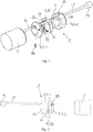
- the in the Fig. 1 Device shown comprises a arranged at the end of a cable 3 camera device 1, which is shown only schematically in the present case, since such camera devices are basically known.
- the cable 3 has at its other end a connection 19 for an extension cable (not shown).
- On the cable 3 several parts of a propulsion device 2 are arranged in a loose arrangement. These comprise a ring body 6 and a first part 7.1 and a further part 7.2 of a multipart base body 7, which must be connected for complete assembly of the device.
- the annular part 7.2 of the body 7 and the ring body 6 were pushed from the side of the terminal 19 forth on the cable 3.
- the cable 3 in an outer peripheral side longitudinal slot 8 and in an outer peripheral side longitudinal groove 9 of the first part 7.1 of the body 7 was inserted.
- the fully assembled device is in the Fig. 2 shown in a side view.
- the annular body 6 and the annular part 7.2 of the main body 7 were pushed onto the first part 7.1 of the main body 7, so that at least the longitudinal groove 9 completely covered and the cable 3 is held captive in the main body 7.
- the annular part 7.2 of the base body 7 was then secured against rotation (see also Fig. 4 ).
- the annular body 6 is mounted rotatably.
- the rotationally movable mounting takes place via the annular part 7.2 of the main body 7, which has a ring body 6 receiving collar-shaped projection 20 to form a sliding bearing 16 (see Fig. 1 and Fig. 4 ). Due to the rotatable mounting of the ring body 6, this is able to one Central longitudinal axis of the main body 7 to rotate.
- a nozzle 4 is formed for a cleaning fluid, which also rotates with rotating annular body 6 about the central longitudinal axis. In this way, a uniform discharge of the cleaning fluid in the circumferential direction is achieved.
- the annular body 6 has a bore 15 which extends obliquely to an imaginary radial (see Fig. 3 ). Since the bore 15 lies on an axis which does not intersect the central longitudinal axis of the main body 7, that is to say the axis of rotation of the annular body 6, a moment is generated via the fluid jet emerging from the nozzle 4, which drives the annular body 6 in a rotational movement.
- a peripheral groove 13 is formed on the inner circumference side in the annular body 6, so that the annular body 6 and the annular part 7.2 of the main body 7 together define an annular space 12 which serves to distribute the fluid over the circumference ( please refer Fig. 3 ).
- the annular space 12 is connected via bores 14, which extend radially through the annular part 7.2 and the first part 7.1 of the main body 7, with a central recess 11 of the first part 7.1 of the main body 7, which is supplied via a hose 5 with fluid ( please refer Fig. 4 ).
- An end portion of the tube 5 is plugged into the central recess 11, preferably screwed or pressed.
- the central recess 11 of the base body 7 is designed as a stepped bore.
- a further tube 5 ' is provided, which connects the camera device 1 with the propulsion device 2 (see Fig. 4 ).
- oblique holes 17 are formed (see FIG. 3 and FIG. 4 ), which are indirectly connected via the holes 14 with the central recess 11, so that they are supplied with fluid.
- the orientation of the inclined bores 17 is such that the fluid discharged therefrom generates a propulsion.
- cleaning of the pipe or pipe section is achieved via the fluid.
- the cable 3 is arranged eccentrically with respect to the central longitudinal axis of the propulsion device 2. This allows a central arrangement of the tube 5 and the tube 5 'while maintaining a radial distance between the cable 3 and the tube 5 or the tube 5'.
- the cable 3 can be removed from the longitudinal slot 8 and the longitudinal groove 9 by loosening the screw 18 and removing the annular part 7.2 including the annular body 6 from the first part 7.1 of the main body 7.
- the camera device 1 can then be removed and replaced by the other camera device 1.
- the annular part 7.2 of the main body 7 has a longitudinal groove 10, which, however, in contrast to the longitudinal groove 9 of the first part 7.1 of the base body 7 is arranged on the inner peripheral side.
- the depth of the longitudinal groove 9 can thus be reduced by the depth of the longitudinal groove 10 in overlapping with the longitudinal groove 9, the longitudinal groove 10 of the area-wise receiving the cable 3. (Fig Fig. 3 ).
Landscapes
- Engineering & Computer Science (AREA)
- Mechanical Engineering (AREA)
- Hydrology & Water Resources (AREA)
- Health & Medical Sciences (AREA)
- Public Health (AREA)
- Water Supply & Treatment (AREA)
- Life Sciences & Earth Sciences (AREA)
- Chemical & Material Sciences (AREA)
- Combustion & Propulsion (AREA)
- General Engineering & Computer Science (AREA)
- Cleaning In General (AREA)
- Instruments For Viewing The Inside Of Hollow Bodies (AREA)
- Investigating Materials By The Use Of Optical Means Adapted For Particular Applications (AREA)
Applications Claiming Priority (1)
| Application Number | Priority Date | Filing Date | Title |
|---|---|---|---|
| DE102016123038.3A DE102016123038A1 (de) | 2016-11-29 | 2016-11-29 | Vorrichtung zur Inspektion und Reinigung eines Leitungs- oder Rohrabschnitts |
Publications (3)
| Publication Number | Publication Date |
|---|---|
| EP3326727A2 true EP3326727A2 (fr) | 2018-05-30 |
| EP3326727A3 EP3326727A3 (fr) | 2018-08-22 |
| EP3326727B1 EP3326727B1 (fr) | 2022-06-08 |
Family
ID=60450431
Family Applications (1)
| Application Number | Title | Priority Date | Filing Date |
|---|---|---|---|
| EP17202676.7A Active EP3326727B1 (fr) | 2016-11-29 | 2017-11-21 | Dispositif d'inspection et de nettoyage de la section de conduite ou de tuyau |
Country Status (2)
| Country | Link |
|---|---|
| EP (1) | EP3326727B1 (fr) |
| DE (1) | DE102016123038A1 (fr) |
Cited By (5)
| Publication number | Priority date | Publication date | Assignee | Title |
|---|---|---|---|---|
| CN109261663A (zh) * | 2018-12-04 | 2019-01-25 | 张若玮 | 电力暗管牵引式清理器 |
| CN110847339A (zh) * | 2019-11-26 | 2020-02-28 | 中铁十八局集团建筑安装工程有限公司 | 一种排水管道定向清淤装置 |
| US20210245207A1 (en) * | 2020-02-07 | 2021-08-12 | Enz Technik Ag | Pipe cleaning and/or inspection nozzle comprising extension sleeve |
| CN113477634A (zh) * | 2021-07-16 | 2021-10-08 | 江苏禹顺建设工程有限公司 | 一种水利工程疏通用清淤装置 |
| CN116498832A (zh) * | 2023-04-28 | 2023-07-28 | 深圳市施罗德工业集团有限公司 | 一种管道检测机器人 |
Family Cites Families (5)
| Publication number | Priority date | Publication date | Assignee | Title |
|---|---|---|---|---|
| JPH11114513A (ja) * | 1997-10-13 | 1999-04-27 | Kantool:Kk | 配管用のカメラ付き高圧ジェット洗浄装置 |
| EP1291991A3 (fr) * | 2001-09-10 | 2005-09-28 | Alcatel | Procédé d'installation d'un élément tubulaire dans une cavité inaccessible à un opérateur |
| DE102009057284B4 (de) | 2009-12-07 | 2020-07-30 | Ritec Rohrinspektionstechnik Gmbh | Vorrichtung zur Inspektion und/oder Reinigung von Leitungen für industrielles, häusliches und gewerbliches Abwasser, insbesondere von Kanalrohren für Abwässer |
| DE202010002714U1 (de) * | 2010-02-24 | 2011-09-07 | Arnold Pläsier | Spülkopf und Spülvorrichtung |
| DE102012012688A1 (de) * | 2012-06-27 | 2014-04-24 | Arnold Pläsier | Drehvorrichtung und Kanalspül- und Inspektionssystem |
-
2016
- 2016-11-29 DE DE102016123038.3A patent/DE102016123038A1/de not_active Ceased
-
2017
- 2017-11-21 EP EP17202676.7A patent/EP3326727B1/fr active Active
Cited By (7)
| Publication number | Priority date | Publication date | Assignee | Title |
|---|---|---|---|---|
| CN109261663A (zh) * | 2018-12-04 | 2019-01-25 | 张若玮 | 电力暗管牵引式清理器 |
| CN110847339A (zh) * | 2019-11-26 | 2020-02-28 | 中铁十八局集团建筑安装工程有限公司 | 一种排水管道定向清淤装置 |
| US20210245207A1 (en) * | 2020-02-07 | 2021-08-12 | Enz Technik Ag | Pipe cleaning and/or inspection nozzle comprising extension sleeve |
| US11975367B2 (en) * | 2020-02-07 | 2024-05-07 | Enz Technik Ag | Pipe cleaning and/or pipe inspection nozzle including extension sleeve |
| CN113477634A (zh) * | 2021-07-16 | 2021-10-08 | 江苏禹顺建设工程有限公司 | 一种水利工程疏通用清淤装置 |
| CN113477634B (zh) * | 2021-07-16 | 2022-10-11 | 江苏禹顺建设工程有限公司 | 一种水利工程疏通用清淤装置 |
| CN116498832A (zh) * | 2023-04-28 | 2023-07-28 | 深圳市施罗德工业集团有限公司 | 一种管道检测机器人 |
Also Published As
| Publication number | Publication date |
|---|---|
| EP3326727B1 (fr) | 2022-06-08 |
| DE102016123038A1 (de) | 2018-05-30 |
| EP3326727A3 (fr) | 2018-08-22 |
Similar Documents
| Publication | Publication Date | Title |
|---|---|---|
| EP3326727B1 (fr) | Dispositif d'inspection et de nettoyage de la section de conduite ou de tuyau | |
| DE102008003968B3 (de) | Bohranlage | |
| EP0157395A2 (fr) | Jet à tourbillons utilisé comme outil de travail hydraulique | |
| DE102011106953B4 (de) | Rotationsdüsenanordnung mit einer Abdichtugspatrone und Verfahren zum Warten einer Rotationsdüsenanordnung | |
| DE102017125733B4 (de) | Einheit für die Kanalrohrinspektion- und/oder -sanierung im Haupt- und Nebenkanal | |
| DE202010010979U1 (de) | Rotationsdüse | |
| DE102011103161A1 (de) | Reinigungsvorrichtung | |
| DE102012112411B3 (de) | Pressbohrlenkvorrichtung | |
| WO2009092659A2 (fr) | Tête d'injection | |
| DE102005050932B3 (de) | Überbohrvorrichtung | |
| WO2010145737A2 (fr) | Dispositif et procédé pour nettoyer des tuyaux et conduits | |
| DE602005000272T2 (de) | Vorrichtung zum Schmieren eines Teils in einem Zusammenbau | |
| CH717511A2 (de) | Rotorkörper einer Rohrreinigungsdüse, mit angeformten Befestigungsmitteln. | |
| DE102010044953B4 (de) | Gerät zum Reinigen von Kanalrohrwänden | |
| DE202015001636U1 (de) | Bohrfräse zur Rohrreinigung | |
| DE102019000932B4 (de) | Vorrichtung zum Bohren in Erdreich und Verfahren zum Warten einer Vorrichtung zum Bohren in Erdreich | |
| EP2158047B1 (fr) | Cylindre en plusieurs parties | |
| DE102017112001B4 (de) | Vorrichtung zum Reinigen von Oberflächen | |
| EP1890068A1 (fr) | Passage rotatif pour un liquide sous haute pression | |
| CH677807A5 (en) | Pipe-cleaning rotor-driving method - deflects pressure medium against impact face to generate torque | |
| CH717510B1 (de) | Rotorkörper einer Kreuzstrahlreinigungsdüse, hergestellt durch additive Fertigung. | |
| DE102007001076B4 (de) | Werkzeug zum Abziehen von Lagern, Buchsen oder dergleichen | |
| DE3141856C2 (de) | Vorrichtung zum Herstellen von Bohrlöchern in Kohle | |
| DE10211833A1 (de) | Vorrichtung zum grabenlosen Austauschen von Leitungen | |
| WO2002092955A2 (fr) | Dispositif de forage |
Legal Events
| Date | Code | Title | Description |
|---|---|---|---|
| PUAI | Public reference made under article 153(3) epc to a published international application that has entered the european phase |
Free format text: ORIGINAL CODE: 0009012 |
|
| STAA | Information on the status of an ep patent application or granted ep patent |
Free format text: STATUS: THE APPLICATION HAS BEEN PUBLISHED |
|
| AK | Designated contracting states |
Kind code of ref document: A2 Designated state(s): AL AT BE BG CH CY CZ DE DK EE ES FI FR GB GR HR HU IE IS IT LI LT LU LV MC MK MT NL NO PL PT RO RS SE SI SK SM TR |
|
| AX | Request for extension of the european patent |
Extension state: BA ME |
|
| PUAL | Search report despatched |
Free format text: ORIGINAL CODE: 0009013 |
|
| AK | Designated contracting states |
Kind code of ref document: A3 Designated state(s): AL AT BE BG CH CY CZ DE DK EE ES FI FR GB GR HR HU IE IS IT LI LT LU LV MC MK MT NL NO PL PT RO RS SE SI SK SM TR |
|
| AX | Request for extension of the european patent |
Extension state: BA ME |
|
| RIC1 | Information provided on ipc code assigned before grant |
Ipc: F16L 101/30 20060101ALN20180718BHEP Ipc: F16L 101/12 20060101ALN20180718BHEP Ipc: B08B 9/049 20060101AFI20180718BHEP Ipc: F16L 55/36 20060101ALI20180718BHEP Ipc: B08B 9/051 20060101ALI20180718BHEP Ipc: E03F 9/00 20060101ALI20180718BHEP |
|
| STAA | Information on the status of an ep patent application or granted ep patent |
Free format text: STATUS: REQUEST FOR EXAMINATION WAS MADE |
|
| 17P | Request for examination filed |
Effective date: 20190129 |
|
| RBV | Designated contracting states (corrected) |
Designated state(s): AL AT BE BG CH CY CZ DE DK EE ES FI FR GB GR HR HU IE IS IT LI LT LU LV MC MK MT NL NO PL PT RO RS SE SI SK SM TR |
|
| GRAP | Despatch of communication of intention to grant a patent |
Free format text: ORIGINAL CODE: EPIDOSNIGR1 |
|
| STAA | Information on the status of an ep patent application or granted ep patent |
Free format text: STATUS: GRANT OF PATENT IS INTENDED |
|
| INTG | Intention to grant announced |
Effective date: 20220204 |
|
| GRAS | Grant fee paid |
Free format text: ORIGINAL CODE: EPIDOSNIGR3 |
|
| GRAA | (expected) grant |
Free format text: ORIGINAL CODE: 0009210 |
|
| STAA | Information on the status of an ep patent application or granted ep patent |
Free format text: STATUS: THE PATENT HAS BEEN GRANTED |
|
| AK | Designated contracting states |
Kind code of ref document: B1 Designated state(s): AL AT BE BG CH CY CZ DE DK EE ES FI FR GB GR HR HU IE IS IT LI LT LU LV MC MK MT NL NO PL PT RO RS SE SI SK SM TR |
|
| REG | Reference to a national code |
Ref country code: AT Ref legal event code: REF Ref document number: 1496558 Country of ref document: AT Kind code of ref document: T Effective date: 20220615 Ref country code: CH Ref legal event code: EP |
|
| REG | Reference to a national code |
Ref country code: DE Ref legal event code: R096 Ref document number: 502017013275 Country of ref document: DE |
|
| REG | Reference to a national code |
Ref country code: IE Ref legal event code: FG4D Free format text: LANGUAGE OF EP DOCUMENT: GERMAN |
|
| REG | Reference to a national code |
Ref country code: LT Ref legal event code: MG9D |
|
| REG | Reference to a national code |
Ref country code: NL Ref legal event code: MP Effective date: 20220608 |
|
| PG25 | Lapsed in a contracting state [announced via postgrant information from national office to epo] |
Ref country code: SE Free format text: LAPSE BECAUSE OF FAILURE TO SUBMIT A TRANSLATION OF THE DESCRIPTION OR TO PAY THE FEE WITHIN THE PRESCRIBED TIME-LIMIT Effective date: 20220608 Ref country code: NO Free format text: LAPSE BECAUSE OF FAILURE TO SUBMIT A TRANSLATION OF THE DESCRIPTION OR TO PAY THE FEE WITHIN THE PRESCRIBED TIME-LIMIT Effective date: 20220908 Ref country code: LT Free format text: LAPSE BECAUSE OF FAILURE TO SUBMIT A TRANSLATION OF THE DESCRIPTION OR TO PAY THE FEE WITHIN THE PRESCRIBED TIME-LIMIT Effective date: 20220608 Ref country code: HR Free format text: LAPSE BECAUSE OF FAILURE TO SUBMIT A TRANSLATION OF THE DESCRIPTION OR TO PAY THE FEE WITHIN THE PRESCRIBED TIME-LIMIT Effective date: 20220608 Ref country code: GR Free format text: LAPSE BECAUSE OF FAILURE TO SUBMIT A TRANSLATION OF THE DESCRIPTION OR TO PAY THE FEE WITHIN THE PRESCRIBED TIME-LIMIT Effective date: 20220909 Ref country code: FI Free format text: LAPSE BECAUSE OF FAILURE TO SUBMIT A TRANSLATION OF THE DESCRIPTION OR TO PAY THE FEE WITHIN THE PRESCRIBED TIME-LIMIT Effective date: 20220608 Ref country code: ES Free format text: LAPSE BECAUSE OF FAILURE TO SUBMIT A TRANSLATION OF THE DESCRIPTION OR TO PAY THE FEE WITHIN THE PRESCRIBED TIME-LIMIT Effective date: 20220608 Ref country code: BG Free format text: LAPSE BECAUSE OF FAILURE TO SUBMIT A TRANSLATION OF THE DESCRIPTION OR TO PAY THE FEE WITHIN THE PRESCRIBED TIME-LIMIT Effective date: 20220908 |
|
| PG25 | Lapsed in a contracting state [announced via postgrant information from national office to epo] |
Ref country code: RS Free format text: LAPSE BECAUSE OF FAILURE TO SUBMIT A TRANSLATION OF THE DESCRIPTION OR TO PAY THE FEE WITHIN THE PRESCRIBED TIME-LIMIT Effective date: 20220608 Ref country code: LV Free format text: LAPSE BECAUSE OF FAILURE TO SUBMIT A TRANSLATION OF THE DESCRIPTION OR TO PAY THE FEE WITHIN THE PRESCRIBED TIME-LIMIT Effective date: 20220608 |
|
| PG25 | Lapsed in a contracting state [announced via postgrant information from national office to epo] |
Ref country code: NL Free format text: LAPSE BECAUSE OF FAILURE TO SUBMIT A TRANSLATION OF THE DESCRIPTION OR TO PAY THE FEE WITHIN THE PRESCRIBED TIME-LIMIT Effective date: 20220608 |
|
| PG25 | Lapsed in a contracting state [announced via postgrant information from national office to epo] |
Ref country code: SM Free format text: LAPSE BECAUSE OF FAILURE TO SUBMIT A TRANSLATION OF THE DESCRIPTION OR TO PAY THE FEE WITHIN THE PRESCRIBED TIME-LIMIT Effective date: 20220608 Ref country code: SK Free format text: LAPSE BECAUSE OF FAILURE TO SUBMIT A TRANSLATION OF THE DESCRIPTION OR TO PAY THE FEE WITHIN THE PRESCRIBED TIME-LIMIT Effective date: 20220608 Ref country code: RO Free format text: LAPSE BECAUSE OF FAILURE TO SUBMIT A TRANSLATION OF THE DESCRIPTION OR TO PAY THE FEE WITHIN THE PRESCRIBED TIME-LIMIT Effective date: 20220608 Ref country code: PT Free format text: LAPSE BECAUSE OF FAILURE TO SUBMIT A TRANSLATION OF THE DESCRIPTION OR TO PAY THE FEE WITHIN THE PRESCRIBED TIME-LIMIT Effective date: 20221010 Ref country code: EE Free format text: LAPSE BECAUSE OF FAILURE TO SUBMIT A TRANSLATION OF THE DESCRIPTION OR TO PAY THE FEE WITHIN THE PRESCRIBED TIME-LIMIT Effective date: 20220608 Ref country code: CZ Free format text: LAPSE BECAUSE OF FAILURE TO SUBMIT A TRANSLATION OF THE DESCRIPTION OR TO PAY THE FEE WITHIN THE PRESCRIBED TIME-LIMIT Effective date: 20220608 |
|
| PG25 | Lapsed in a contracting state [announced via postgrant information from national office to epo] |
Ref country code: PL Free format text: LAPSE BECAUSE OF FAILURE TO SUBMIT A TRANSLATION OF THE DESCRIPTION OR TO PAY THE FEE WITHIN THE PRESCRIBED TIME-LIMIT Effective date: 20220608 Ref country code: IS Free format text: LAPSE BECAUSE OF FAILURE TO SUBMIT A TRANSLATION OF THE DESCRIPTION OR TO PAY THE FEE WITHIN THE PRESCRIBED TIME-LIMIT Effective date: 20221008 |
|
| REG | Reference to a national code |
Ref country code: DE Ref legal event code: R097 Ref document number: 502017013275 Country of ref document: DE |
|
| PG25 | Lapsed in a contracting state [announced via postgrant information from national office to epo] |
Ref country code: AL Free format text: LAPSE BECAUSE OF FAILURE TO SUBMIT A TRANSLATION OF THE DESCRIPTION OR TO PAY THE FEE WITHIN THE PRESCRIBED TIME-LIMIT Effective date: 20220608 |
|
| PLBE | No opposition filed within time limit |
Free format text: ORIGINAL CODE: 0009261 |
|
| STAA | Information on the status of an ep patent application or granted ep patent |
Free format text: STATUS: NO OPPOSITION FILED WITHIN TIME LIMIT |
|
| PG25 | Lapsed in a contracting state [announced via postgrant information from national office to epo] |
Ref country code: DK Free format text: LAPSE BECAUSE OF FAILURE TO SUBMIT A TRANSLATION OF THE DESCRIPTION OR TO PAY THE FEE WITHIN THE PRESCRIBED TIME-LIMIT Effective date: 20220608 |
|
| 26N | No opposition filed |
Effective date: 20230310 |
|
| PG25 | Lapsed in a contracting state [announced via postgrant information from national office to epo] |
Ref country code: SI Free format text: LAPSE BECAUSE OF FAILURE TO SUBMIT A TRANSLATION OF THE DESCRIPTION OR TO PAY THE FEE WITHIN THE PRESCRIBED TIME-LIMIT Effective date: 20220608 |
|
| PG25 | Lapsed in a contracting state [announced via postgrant information from national office to epo] |
Ref country code: MC Free format text: LAPSE BECAUSE OF FAILURE TO SUBMIT A TRANSLATION OF THE DESCRIPTION OR TO PAY THE FEE WITHIN THE PRESCRIBED TIME-LIMIT Effective date: 20220608 |
|
| GBPC | Gb: european patent ceased through non-payment of renewal fee |
Effective date: 20221121 |
|
| REG | Reference to a national code |
Ref country code: BE Ref legal event code: MM Effective date: 20221130 |
|
| PG25 | Lapsed in a contracting state [announced via postgrant information from national office to epo] |
Ref country code: LU Free format text: LAPSE BECAUSE OF NON-PAYMENT OF DUE FEES Effective date: 20221121 |
|
| PG25 | Lapsed in a contracting state [announced via postgrant information from national office to epo] |
Ref country code: IE Free format text: LAPSE BECAUSE OF NON-PAYMENT OF DUE FEES Effective date: 20221121 Ref country code: GB Free format text: LAPSE BECAUSE OF NON-PAYMENT OF DUE FEES Effective date: 20221121 |
|
| PG25 | Lapsed in a contracting state [announced via postgrant information from national office to epo] |
Ref country code: BE Free format text: LAPSE BECAUSE OF NON-PAYMENT OF DUE FEES Effective date: 20221130 |
|
| PG25 | Lapsed in a contracting state [announced via postgrant information from national office to epo] |
Ref country code: IT Free format text: LAPSE BECAUSE OF FAILURE TO SUBMIT A TRANSLATION OF THE DESCRIPTION OR TO PAY THE FEE WITHIN THE PRESCRIBED TIME-LIMIT Effective date: 20220608 |
|
| PG25 | Lapsed in a contracting state [announced via postgrant information from national office to epo] |
Ref country code: HU Free format text: LAPSE BECAUSE OF FAILURE TO SUBMIT A TRANSLATION OF THE DESCRIPTION OR TO PAY THE FEE WITHIN THE PRESCRIBED TIME-LIMIT; INVALID AB INITIO Effective date: 20171121 |
|
| PG25 | Lapsed in a contracting state [announced via postgrant information from national office to epo] |
Ref country code: CY Free format text: LAPSE BECAUSE OF FAILURE TO SUBMIT A TRANSLATION OF THE DESCRIPTION OR TO PAY THE FEE WITHIN THE PRESCRIBED TIME-LIMIT Effective date: 20220608 |
|
| PG25 | Lapsed in a contracting state [announced via postgrant information from national office to epo] |
Ref country code: MK Free format text: LAPSE BECAUSE OF FAILURE TO SUBMIT A TRANSLATION OF THE DESCRIPTION OR TO PAY THE FEE WITHIN THE PRESCRIBED TIME-LIMIT Effective date: 20220608 |
|
| PG25 | Lapsed in a contracting state [announced via postgrant information from national office to epo] |
Ref country code: MT Free format text: LAPSE BECAUSE OF FAILURE TO SUBMIT A TRANSLATION OF THE DESCRIPTION OR TO PAY THE FEE WITHIN THE PRESCRIBED TIME-LIMIT Effective date: 20220608 |
|
| PG25 | Lapsed in a contracting state [announced via postgrant information from national office to epo] |
Ref country code: BG Free format text: LAPSE BECAUSE OF FAILURE TO SUBMIT A TRANSLATION OF THE DESCRIPTION OR TO PAY THE FEE WITHIN THE PRESCRIBED TIME-LIMIT Effective date: 20220608 |
|
| PG25 | Lapsed in a contracting state [announced via postgrant information from national office to epo] |
Ref country code: BG Free format text: LAPSE BECAUSE OF FAILURE TO SUBMIT A TRANSLATION OF THE DESCRIPTION OR TO PAY THE FEE WITHIN THE PRESCRIBED TIME-LIMIT Effective date: 20220608 |
|
| REG | Reference to a national code |
Ref country code: CH Ref legal event code: U11 Free format text: ST27 STATUS EVENT CODE: U-0-0-U10-U11 (AS PROVIDED BY THE NATIONAL OFFICE) Effective date: 20251201 |
|
| PG25 | Lapsed in a contracting state [announced via postgrant information from national office to epo] |
Ref country code: TR Free format text: LAPSE BECAUSE OF FAILURE TO SUBMIT A TRANSLATION OF THE DESCRIPTION OR TO PAY THE FEE WITHIN THE PRESCRIBED TIME-LIMIT Effective date: 20220608 |
|
| PGFP | Annual fee paid to national office [announced via postgrant information from national office to epo] |
Ref country code: DE Payment date: 20251126 Year of fee payment: 9 |
|
| PGFP | Annual fee paid to national office [announced via postgrant information from national office to epo] |
Ref country code: AT Payment date: 20251124 Year of fee payment: 9 |
|
| PGFP | Annual fee paid to national office [announced via postgrant information from national office to epo] |
Ref country code: FR Payment date: 20251120 Year of fee payment: 9 |
|
| PGFP | Annual fee paid to national office [announced via postgrant information from national office to epo] |
Ref country code: CH Payment date: 20251201 Year of fee payment: 9 |