EP3326858B1 - Fahrzeugsitz, insbesondere ein kraftfahrzeugsitz - Google Patents
Fahrzeugsitz, insbesondere ein kraftfahrzeugsitz Download PDFInfo
- Publication number
- EP3326858B1 EP3326858B1 EP17203538.8A EP17203538A EP3326858B1 EP 3326858 B1 EP3326858 B1 EP 3326858B1 EP 17203538 A EP17203538 A EP 17203538A EP 3326858 B1 EP3326858 B1 EP 3326858B1
- Authority
- EP
- European Patent Office
- Prior art keywords
- adapter
- vehicle seat
- catch
- fitting
- spring element
- Prior art date
- Legal status (The legal status is an assumption and is not a legal conclusion. Google has not performed a legal analysis and makes no representation as to the accuracy of the status listed.)
- Active
Links
Images


Classifications
-
- B—PERFORMING OPERATIONS; TRANSPORTING
- B60—VEHICLES IN GENERAL
- B60N—SEATS SPECIALLY ADAPTED FOR VEHICLES; VEHICLE PASSENGER ACCOMMODATION NOT OTHERWISE PROVIDED FOR
- B60N2/00—Seats specially adapted for vehicles; Arrangement or mounting of seats in vehicles
- B60N2/02—Seats specially adapted for vehicles; Arrangement or mounting of seats in vehicles the seat or part thereof being movable, e.g. adjustable
- B60N2/22—Seats specially adapted for vehicles; Arrangement or mounting of seats in vehicles the seat or part thereof being movable, e.g. adjustable the back-rest being adjustable
- B60N2/235—Seats specially adapted for vehicles; Arrangement or mounting of seats in vehicles the seat or part thereof being movable, e.g. adjustable the back-rest being adjustable by gear-pawl type mechanisms
- B60N2/2356—Seats specially adapted for vehicles; Arrangement or mounting of seats in vehicles the seat or part thereof being movable, e.g. adjustable the back-rest being adjustable by gear-pawl type mechanisms with internal pawls
-
- B—PERFORMING OPERATIONS; TRANSPORTING
- B60—VEHICLES IN GENERAL
- B60N—SEATS SPECIALLY ADAPTED FOR VEHICLES; VEHICLE PASSENGER ACCOMMODATION NOT OTHERWISE PROVIDED FOR
- B60N2/00—Seats specially adapted for vehicles; Arrangement or mounting of seats in vehicles
- B60N2/02—Seats specially adapted for vehicles; Arrangement or mounting of seats in vehicles the seat or part thereof being movable, e.g. adjustable
- B60N2/0296—Central command actuator to selectively switch on or engage one of several special purpose circuits or mechanisms
-
- B—PERFORMING OPERATIONS; TRANSPORTING
- B60—VEHICLES IN GENERAL
- B60N—SEATS SPECIALLY ADAPTED FOR VEHICLES; VEHICLE PASSENGER ACCOMMODATION NOT OTHERWISE PROVIDED FOR
- B60N2/00—Seats specially adapted for vehicles; Arrangement or mounting of seats in vehicles
- B60N2/02—Seats specially adapted for vehicles; Arrangement or mounting of seats in vehicles the seat or part thereof being movable, e.g. adjustable
- B60N2/22—Seats specially adapted for vehicles; Arrangement or mounting of seats in vehicles the seat or part thereof being movable, e.g. adjustable the back-rest being adjustable
- B60N2/2222—Seats specially adapted for vehicles; Arrangement or mounting of seats in vehicles the seat or part thereof being movable, e.g. adjustable the back-rest being adjustable the back-rest having two or more parts
-
- B—PERFORMING OPERATIONS; TRANSPORTING
- B60—VEHICLES IN GENERAL
- B60N—SEATS SPECIALLY ADAPTED FOR VEHICLES; VEHICLE PASSENGER ACCOMMODATION NOT OTHERWISE PROVIDED FOR
- B60N2205/00—General mechanical or structural details
- B60N2205/50—Interlocking shaft arrangements transmitting movement between hinge mechanisms on both sides of a seat
Definitions
- the invention relates to a vehicle seat, in particular a motor vehicle seat, with a seat part, a backrest adjustable in its inclination, at least one fitting for pivotably mounting the backrest on the seat part, wherein an inclination setting of the backrest can be locked by means of the fitting, and a handle for actuating an unlocking of the fitting.
- Vehicle seats are known in which the backrests can be adjusted in their inclination relative to a seat part.
- an occupant sitting in the vehicle seat needs to be able to operate the seat in order to adjust this large number of different functions.
- the US 2009/134679 A1 discloses a control device for regulating the adjustment of vehicle seats.
- the control device is a dual function control arm which combines the manual recliner and the lumbar mechanism in a single handle.
- the handle is moved in a first direction to release the backrest mechanism without affecting the lumbar adjustment mechanism.
- the same handle is moved in a second direction to operate the lumbar adjustment mechanism without affecting the recliner mechanism.
- the DE 10 2007 027564 A1 discloses a seat adjustment device comprising a first locking mechanism which is movable between an engaged position in which a vehicle seat bottom is movable forwards or backwards relative to the vehicle floor, and an engaged position in which the seat bottom is prevented from moving.
- a second locking mechanism is movable between a disengaged position in which a seat back of the vehicle seat device is pivotally movable forwards or backwards relative to the seat bottom, and an engaged position in which the seat back is prevented from moving.
- An actuating mechanism is mechanically connected to the first and second locking mechanisms and is movable between a first actuating position and a second actuating position. In the first actuating position, the first locking mechanism is in the disengaged position and the second locking mechanism remains in the engaged position. In the second actuating position, the second locking mechanism is in the disengaged position and the first locking mechanism remains in the engaged position.
- a vehicle seat with a seat part from the US 4 626 028 A known in which a lower backrest section of a two-part backrest is adjustable in its inclination to the seat part by a fitting and an upper backrest section is adjustable in its inclination relative to the lower backrest section by a fitting.
- the invention is based on the object of improving a vehicle seat of the type mentioned at the outset, in particular to provide a vehicle seat with a reduced number of actuating means despite the same number of adjustment components, or to provide a vehicle seat with an increased number of adjustment components despite the same number of actuating means.
- the vehicle seat in particular a motor vehicle seat, has a seat part, a backrest whose inclination is adjustable, at least one fitting for pivotably mounting the backrest on the seat part, and a handle for unlocking the fitting, wherein an angle of inclination of the backrest can be locked by means of the fitting, wherein an adapter is rotatably mounted and coupled to the fitting, wherein a driver is arranged between the handle and the adapter, wherein the driver interacts with the adapter in a first direction of rotation in a coupled manner, and a rotation of the driver in the first direction of rotation unlocks the fitting, wherein a rotation of the driver in a second direction of rotation actuates a locking device of a further adjustment component of the vehicle seat.
- an adapter is rotatably mounted and coupled to the fitting, wherein a driver is arranged between the handle and the adapter, wherein the driver interacts with the adapter in a first direction of rotation in a coupled manner, and a rotation of the driver in the first direction of rotation unlocks the fitting, wherein a rotation of the driver in a second direction of rotation actuates a locking device of a further adjustment component of the vehicle seat, the fitting for adjusting the angle of inclination of the backrest can be unlocked by means of the handle, and when actuated in the opposite direction of rotation, a locking device of a further adjustment component of the vehicle seat can be released, unlocked or actuated.
- a shaft extending in a transverse direction can be provided, which is operatively connected to the at least one fitting such that rotation of the shaft unlocks the fitting.
- a second fitting can be provided, which is arranged on a side of the vehicle seat opposite the first fitting.
- the shaft can be arranged coaxially to a pivot axis of the backrest.
- the two fittings can be operatively connected by means of the shaft, so that both fittings can be unlocked at the same time.
- a through-opening of the adapter and an opening of the driver can be arranged coaxially to the shaft.
- the adapter can be connected to the shaft in a rotationally fixed manner.
- the adapter can be made of a plastic material.
- the adapter can be manufactured using an injection molding process.
- the adapter can be operatively connected to the fitting.
- the driver can have a stop surface (a stop).
- the adapter can have a stop surface, in particular a stop surface oriented perpendicular to a circumferential direction.
- the driver can have a stop in the area of an opening, which can be brought into contact with the stop surface of the adapter by rotating the driver in a predetermined direction of rotation.
- a one-sided coupling for driving can be provided by means of the stop of the driver and the stop surface of the adapter. In a direction of rotation opposite to the previously mentioned direction of rotation, the driver can be rotatable independently of the adapter, in particular rotatable along an idle path.
- a first spring element can act between the adapter and the fitting in order to preload the adapter in the direction of a basic position.
- the first spring element can be a spiral spring.
- the adapter can be preloaded by means of the first spring element.
- the adapter can be preloaded by means of the first spring element in a first direction of rotation, in particular in the direction of a first end position of the adapter in which the fitting is locked.
- the end position of the adapter is defined relative to the vehicle seat.
- the adapter can be rotatable in a second direction of rotation starting from a first end position, for example rotatable by up to 30°.
- a second spring element can act between the adapter and the driver in order to preload the driver in the direction of a basic position.
- the second spring element can be a spiral spring.
- the driver can be preloaded by means of the second spring element.
- the driver can be preloaded by means of the second spring element in a second direction of rotation, in particular in the direction of a first end position of the driver, in which a stop of the driver and a stop surface of the adapter are in contact.
- the first end position of the driver is defined in relation to the adapter and is displaced in accordance with the rotation when the adapter is rotated.
- the second spring element preferably acts on the driver in an opposite direction of rotation to that of the first spring element on the adapter.
- the driver can be rotatable in a first direction of rotation starting from its first end position, for example rotatable by up to 20°.
- the driver can have at least one cam, in particular a radially protruding cam, which interacts with a projection of the adapter when the adapter is rotated together with the driver along the second direction of rotation.
- the driver can have an arm, in particular a radially protruding arm.
- the arm can have a receptacle for connecting an end section of a Bowden cable.
- the end of the Bowden cable opposite the arm can be operatively connected to the locking device of another adjustment component of the vehicle seat.
- the further adjustment component of the vehicle seat serves to adjust an inclination of an upper backrest section of a two-part backrest relative to a lower backrest section of the two-part backrest.
- the invention also relates to a motor vehicle, in particular a commercial vehicle (e.g. a bus or a truck), with a vehicle seat as disclosed herein.
- a motor vehicle in particular a commercial vehicle (e.g. a bus or a truck), with a vehicle seat as disclosed herein.
- Fig. 1 shows a vehicle seat 1 according to the invention.
- the vehicle seat 1 has a seat part 3 and a backrest 5 whose inclination can be adjusted.
- At least one fitting 10 is provided on the seat part 3, wherein an inclination setting of the backrest 5 can be locked by means of the fitting 10.
- a fitting 10 is preferably arranged on each side of the vehicle seat 1.
- a handle 7 for actuating an unlocking of the fitting 10 is shown, which in the present case is arranged in alignment with the fitting 10.
- the vehicle seat 1 can be included in particular in a motor vehicle, in particular a commercial vehicle.
- the commercial vehicle can be a bus or a truck.
- Fig. 2 shows a perspective view of a fitting system of the vehicle seat 1 from Fig. 1
- the fitting system has two fittings 10, each of which can be mounted on an opposite side of the vehicle seat 1.
- the fittings 10 are designed in the form of locking fittings known from the prior art, such as those known from DE 102008024853 A1 are known.
- the fittings 10 each have a lower fitting part 10a and an upper fitting part 10b, which can be rotated relative to one another when the fitting 10 is unlocked.
- the lower fitting part 10a is known to be connectable to a frame part of the seat part 3 of the vehicle seat 1, wherein the upper fitting part 10b is connectable to a frame section of the backrest 5 of the vehicle seat 1.
- a shaft 12 extending in a transverse direction y is provided, which is operatively connected to the two fittings 10 in this case.
- the shaft 12 is arranged coaxially to a pivot axis of the backrest 5.
- the two fittings 10 are operatively connected to one another by means of the shaft 12, which can also be referred to as a transmission rod, in such a way that actuation of the shaft 12 unlocks or locks both fittings 10, or the actuation movement of one of the two fittings 10 can be transferred to the other fitting 10 by means of the shaft 12.
- the handle 7 is arranged in alignment with the shaft 12 and operatively connected to the shaft 12. In other words, the two fittings 10 are operatively connected by means of the shaft 12, so that both fittings 10 can be unlocked at the same time using just one handle 7.
- the Figures 3 and 4 shown components are arranged. These are an adapter 20, a driver 30, a first spring element 40 and a second spring element 50.
- the first spring element 40 has the shape of a leg spring.
- the second spring element 50 has the shape of a leg spring.
- the driver 30 has an arm 36, at whose free end a receptacle for connection to an end section of a Bowden cable 60 is provided.
- Fig. 5 shows a partial view of the vehicle seat 1 with the components according to Fig. 4 which are arranged around an end section of the shaft 12.
- the adapter 20 is directly connected in a rotationally fixed manner to the shaft 12, which in turn is operatively connected in a rotationally fixed manner to the two fittings 10.
- the adapter 20 is arranged to act on the fitting 10.
- the driver 30 is attached to the adapter 20.
- the driver 30 is coupled to the adapter 20 in a first direction of rotation 80 to unlock the fitting 10.
- a locking device 70 of a further adjustment component of the vehicle seat 1 can also be actuated when the driver 30 is moved along a second direction of rotation 82.
- the Bowden cable 60 is operatively connected with its end opposite the arm 36 of the driver 30 to the locking device 70 of the further adjustment component of the vehicle seat 1, in particular connected to an actuating lever 72 of the locking device 70.
- the further adjustment component of the vehicle seat 1 can be used to adjust an inclination of the seat part 3 or to adjust an inclination of an upper backrest section 5b, relative to a lower backrest section 5a, of a two-part backrest 5.
- Fig. 6 shows a partial representation of the vehicle seat 1, starting from the vehicle seat 1 according to Fig. 5 First, a side cover is mounted and then the handle 7 is mounted flush with the shaft 12. The handle 7 is connected to the driver 30 in a rotationally fixed manner.
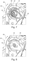
- Fig. 7 shows an enlarged view of the adapter 20 mounted on the fitting 10 of the vehicle seat 1, with the driver 30 arranged thereon.
- the adapter 20 has a through opening 22 that deviates from a rotationally symmetrical cross section, by means of which it can be plugged onto the shaft 12. Due to the non-rotationally symmetrical opening cross section, the adapter 20 is connected to the shaft 12 in a rotationally fixed manner, with the shaft 12 preferably having a correspondingly cooperating cross section.
- the shaft 12 has a splined shaft profile.
- the adapter 20 has a stop surface 24, in particular a stop surface 24 oriented perpendicular to a circumferential direction.
- the driver 30 has in the region of an opening 38 has a stop 32 which can be brought into contact with the stop surface 24 of the adapter 20 by rotating the driver 30 in a direction of rotation 80.
- a one-sided coupling for driving is provided by means of the stop 32 of the driver 30 and the stop surface 24 of the adapter 20.
- the driver 30 In a direction of rotation 82 opposite to the previously mentioned direction of rotation 80, the driver 30 can be rotated independently of the adapter 20, in particular along an idle path.
- the in Fig. 7 The state of the components shown represents a basic position of the driver 30 and the adapter 20, in which the fittings 10 and the locking device 70 are not actuated.
- the first spring element 40 is arranged between the adapter 20 and the fitting 10 in order to transfer the adapter 20 into the basic position.
- the adapter 20 is preloaded by means of the first spring element 40 in the direction of rotation 82 in the direction of a first end position of the adapter 20.
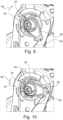
- the end position of the adapter 20 is defined relative to the vehicle seat 1 and can be predetermined, for example, by means of an end stop. Starting from the first end position of the adapter 20, which corresponds to the basic position, the adapter 20 can be rotated in the direction of rotation 80, for example by up to 30°. In the basic position, the two fittings 10 are locked. This state is in Fig. 9 shown.
- the second spring element 50 is arranged to act between the adapter 20 and the driver 30.
- One spring end of the second spring element 50 is supported on the adapter 20 and the driver 30.
- the second spring element 50 serves to transfer the driver 30 into a basic position relative to the adapter 20.
- the driver 30 is preloaded by means of the second spring element 50 in the direction of rotation 80 in the direction of the basic position of the driver 30, in which the stop 32 of the driver 30 and the stop surface 24 of the adapter 20 are in contact.
- the basic position of the driver 30 shown is defined in relation to the adapter 20 and is displaced when the adapter 20 is rotated in accordance with the rotation.
- the second spring element 50 acts in the first direction of rotation 80 on the driver 30.
- the first spring element 40 acts in a second direction of rotation 82 on the adapter 20.
- the driver 30 can be rotated in the direction of rotation 82 starting from its end position, for example by up to 20°.
- the stop 32 is released from the stop surface 24. This state is in Fig. 10 shown.
- Fig. 8 is a sectional view of the driver 30 and the adapter 20.
- the driver 30 has three radially projecting cams 34, which are accommodated in pocket-like projections 26 of the adapter 20, provided that the driver 30 is in the basic position.
- the pocket-like projections 26 are open radially inwards and in the direction of rotation 82.
- the pocket-like projections 26 are closed radially outwards and in the direction of rotation 80. If the driver 30 is rotated relative to the adapter 20, the cams 34 rotate out of the projections 26. If the driver 30 is rotated in the direction of rotation 80, the cams 34 are in engagement with the projections 26 and thereby safely transmit the rotational force into the adapter 20 and rotate it in the same direction of rotation 80.
Landscapes
- Engineering & Computer Science (AREA)
- Aviation & Aerospace Engineering (AREA)
- Transportation (AREA)
- Mechanical Engineering (AREA)
- Seats For Vehicles (AREA)
Description
- Die Erfindung betrifft einen Fahrzeugsitz, insbesondere einen Kraftfahrzeugsitz, mit einem Sitzteil, einer in ihrer Neigung einstellbaren Lehne, wenigstens einem Beschlag zur schwenkbaren Lagerung der Lehne an dem Sitzteil, wobei eine Neigungseinstellung der Lehne mittels des Beschlags arretierbar ist, und einem Handgriff zur Betätigung einer Entriegelung des Beschlags.
- Es sind Fahrzeugsitze bekannt, deren Lehnen relativ zu einem Sitzteil in ihrer Neigung einstellbar sind. Mit fortschreitender Technik und zunehmender Integration einer Vielzahl an Funktionen und Einstellmöglichkeiten bei Fahrzeugsitzen, bedarf es einer jeweiligen Betätigungsmöglichkeit durch einen in dem Fahrzeugsitz sitzenden Insassen, um diese Vielzahl an unterschiedlichen Funktionen einzustellen.
- Die
US 2009/134679 A1 offenbart eine Steuervorrichtung zum Regeln der Einstellung von Fahrzeugsitzen. Die Steuervorrichtung ist ein Doppelfunktions-Steuerarm, der den manuellen Liegestuhl und den Lendenwirbelmechanismus in einem einzigen Griff vereint. Der Griff wird in eine erste Richtung bewegt, um den Mechanismus der Rückenlehne zu lösen, ohne den Mechanismus der Lendenverstellung zu beeinflussen. Der gleiche Griff wird in eine zweite Richtung bewegt, um den Lendenverstellmechanismus zu betätigen, ohne den Liegemechanismus zu beeinflussen. - Die
DE 10 2007 027564 A1 offenbart eine Sitzverstellvorrichtung umfassend einen ersten Verriegelungsmechanismus, der zwischen einer eingerückten Position, in welcher ein Fahrzeugsitzunterteil relativ zu dem Fahrzeugboden nach vorne oder hinten bewegbar ist, und einer eingerückten Position beweglich ist, in welcher der Sitzunterteil an einer Bewegung gehindert ist. Ein zweiter Verriegelungsmechanismus ist zwischen einer ausgerückten Position, in welcher eine Sitzlehne der Fahrzeugsitzeinrichtung relativ zu dem Sitzunterteil schwenkend nach vorne oder hinten bewegbar ist, und einer eingerückten Position beweglich, in welcher die Sitzlehne daran gehindert wird, sich zu bewegen. Ein Betätigungsmechanismus ist mit dem ersten und zweiten Verriegelungsmechanismus mechanisch verbunden und zwischen einer ersten Betätigungsposition und einer zweiten Betätigungsposition beweglich. In der ersten Betätigungsposition ist der erste Verriegelungsmechanismus in der ausgerückten Position und bleibt der zweite Verriegelungsmechanismus in der eingerückten Position. In der zweiten Betätigungsposition ist der zweite Verriegelungsmechanismus in der ausgerückten Position und verbleibt der erste Verriegelungsmechanismus in der eingerückten Position. - Weitere Fahrzeugsitze sind bspw. aus der
EP 1 099 593 A2 und derFR 2 829 439 A1 US 4 626 028 A bekannt, bei dem ein unterer Lehnenabschnitt einer zweiteiligen Lehne durch einen Beschlag in seiner Neigung zum Sitzteil einstellbar ist und ein oberer Lehnenabschnitt durch einen Beschlag in seiner Neigung relativ zu dem unteren Lehnenabschnitt einstellbar ist. - Der Erfindung liegt die Aufgabe zu Grunde, einen Fahrzeugsitz der eingangs genannten Art zu verbessern, insbesondere einen Fahrzeugsitz mit einer reduzierten Anzahl an Betätigungsmitteln trotz gleichbleibender Anzahl an Einstellkomponenten, bzw. einen Fahrzeugsitz mit einer erhöhten Anzahl an Einstellkomponenten trotz gleichbleibender Anzahl an Betätigungsmitteln bereitzustellen.
- Diese Aufgabe wird erfindungsgemäß gelöst durch einen Fahrzeugsitz gemäß Anspruch 1. Der Fahrzeugsitz, insbesondere Kraftfahrzeugsitz, weist einen Sitzteil, eine in ihrer Neigung einstellbare Lehne, wenigstens einen Beschlag zur schwenkbaren Lagerung der Lehne an dem Sitzteil, und einen Handgriff zur Entriegelung des Beschlags auf, wobei ein Neigungswinkel der Lehne mittels des Beschlags arretierbar ist, wobei ein Adapter drehbar gelagert und mit dem Beschlag gekoppelt ist, wobei zwischen dem Handgriff und dem Adapter ein Mitnehmer angeordnet ist, wobei der Mitnehmer mit dem Adapter in einer ersten Drehrichtung auf Mitnahme gekoppelt zusammenwirkt, und eine Drehung des Mitnehmers in der ersten Drehrichtung den Beschlag entriegelt, wobei eine Drehung des Mitnehmers in einer zweiten Drehrichtung eine Verriegelungsvorrichtung einer weiteren Einstellkomponente des Fahrzeugsitzes betätigt.
- Dadurch, dass ein Adapter drehbar gelagert und mit dem Beschlag gekoppelt ist, wobei zwischen dem Handgriff und dem Adapter ein Mitnehmer angeordnet ist, wobei der Mitnehmer mit dem Adapter in einer ersten Drehrichtung auf Mitnahme gekoppelt zusammenwirkt, und eine Drehung des Mitnehmers in der ersten Drehrichtung den Beschlag entriegelt, wobei eine Drehung des Mitnehmers in einer zweiten Drehrichtung eine Verriegelungsvorrichtung einer weiteren Einstellkomponente des Fahrzeugsitzes betätigt, kann mittels des Handgriffs sowohl der Beschlag zur Einstellung des Neigungswinkels der Lehne entriegelt werden, als auch bei einer Betätigung in entgegengesetzter Drehrichtung eine Verriegelungsvorrichtung einer weiteren Einstellkomponente des Fahrzeugsitzes freigegeben oder entriegelt oder betätigt werden.
- Vorteilhafte Ausgestaltungen, welche einzeln oder in Kombination miteinander eingesetzt werden können, sind Gegenstand der Unteransprüche.
- Ferner kann eine sich in einer Querrichtung erstreckende Welle vorgesehen sein, welche mit dem wenigsten einen Beschlag derart wirkverbunden ist, dass eine Drehung der Welle den Beschlag entriegelt. Ferner kann ein zweiter Beschlag vorgesehen sein, welcher an einer dem ersten Beschlag gegenüberliegenden Seite des Fahrzeugsitzes angeordnet ist. Die Welle kann koaxial zu einer Schwenkachse der Lehne angeordnet sein. Die beiden Beschläge können mittels der Welle wirkverbunden sein, so dass beide Beschläge zeitgleich entriegelbar sind.
- Eine Durchgangsöffnung des Adapters und eine Öffnung des Mitnehmers können koaxial zur Welle angeordnet sein. Der Adapter kann drehfest mit der Welle verbunden sein. Der Adapter kann aus einem Kunststoffmaterial gefertigt sein. Der Adapter kann mittels eines Spritzgussverfahrens gefertigt sein. Der Adapter kann mit dem Beschlag wirkverbunden sein. Der Mitnehmer kann eine Anschlagsfläche (einen Anschlag) aufweisen. Der Adapter kann eine Anschlagsfläche aufweisen, insbesondere eine senkrecht zu einer Umfangsrichtung orientierten Anschlagsfläche. Der Mitnehmer kann im Bereich einer Öffnung einen Anschlag aufweisen, welcher durch eine Drehung des Mitnehmers in einer vorgegebenen Drehrichtung mit der Anschlagsfläche des Adapters in Kontakt bringbar ist. Mittels des Anschlags des Mitnehmers und der Anschlagfläche des Adapters kann eine einseitige Kopplung auf Mitnahme bereitstellbar sein. In einer der zuvor genannten Drehrichtung entgegengesetzte Drehrichtung kann der Mitnehmer unabhängig von dem Adapter drehbar sein, insbesondere entlang eines Leerweges drehbar sein.
- Ein erstes Federelement kann zwischen Adapter und Beschlag wirken, um den Adapter in Richtung einer Grundstellung vorzuspannen. Das erste Federelement kann eine Spiralfeder sein. Der Adapter kann mittels des ersten Federelements vorgespannt sein. Der Adapter kann mittels des ersten Federelements in einer ersten Drehrichtung, insbesondere in Richtung einer ersten Endstellung des Adapters, in welcher der Beschlag verriegelt ist, vorgespannt sein. Die Endstellung des Adapters ist relativ zum Fahrzeugsitz definiert. Der Adapter kann ausgehend von einer ersten Endstellung in einer zweiten Drehrichtung drehbar sein, beispielsweise um bis zu 30° drehbar sein.
- Darüber hinaus kann ein zweites Federelement zwischen dem Adapter und dem Mitnehmer wirken, um den Mitnehmer in Richtung einer Grundstellung vorzuspannen. Das zweite Federelement kann eine Spiralfeder sein. Der Mitnehmer kann mittels des zweiten Federelements vorgespannt sein. Der Mitnehmer kann mittels des zweiten Federelements in einer zweiten Drehrichtung, insbesondere in Richtung einer ersten Endstellung des Mitnehmers, in welcher sich ein Anschlag des Mitnehmers und eine Anschlagfläche des Adapters in Anlage befinden, vorgespannt sein. Die erste Endstellung des Mitnehmers ist in Relation zum Adapter definiert und wird bei einer Drehung des Adapters entsprechend der Drehung mit verlagert. Das zweite Federelement wirkt bevorzugt in einer entgegengesetzten Drehrichtung auf den Mitnehmer, als das erste Federelement auf den Adapter. Der Mitnehmer kann ausgehend von seiner ersten Endstellung in einer ersten Drehrichtung drehbar sein, beispielsweise um bis zu 20° drehbar sein.
- Der Mitnehmer kann wenigstens einen Nocken, insbesondere einen radial abstehenden Nocken, aufweisen, welcher mit einem Vorsprung des Adapters zusammenwirkt, wenn der Adapter zusammen mit dem Mitnehmer entlang der zweiten Drehrichtung verdreht ist. Der Mitnehmer kann einen Arm aufweisen, insbesondere einen radial abstehenden Arm. Der Arm kann eine Aufnahme zur Verbindung eines Endabschnittes eines Bowdenzuges aufweisen.
- Der Bowdenzug kann mit seinem dem Arm gegenüberliegenden Ende mit der Verriegelungsvorrichtung einer weiteren Einstellkomponente des Fahrzeugsitzes wirkverbunden sein.
- Erfindungsgemäß dient die weitere Einstellkomponente des Fahrzeugsitzes der Einstellung einer Neigung eines oberen Lehnenabschnitts einer zweiteiligen Lehne, relativ zu einem unteren Lehnenabschnitt der zweiteiligen Lehne.
- Die Erfindung betrifft auch ein Kraftfahrzeug, insbesondere ein Nutzfahrzeug (z. B. einen Omnibus oder einen Lastkraftwagen), mit einem Fahrzeugsitz wie hierin offenbart.
- Bevor nachfolgend Ausgestaltungen der Erfindung eingehender an Hand von Zeichnungen beschrieben werden, ist zunächst festzuhalten, dass die Erfindung nicht auf die beschriebenen Komponenten oder die beschriebenen Verfahrensschritte beschränkt ist. Weiterhin stellt auch die verwendete Terminologie keine Einschränkung dar, sondern hat lediglich beispielhaften Charakter. Soweit nachfolgend in der Beschreibung und den Ansprüchen der Singular verwendet wird ist dabei jeweils der Plural mitumfasst, soweit der Kontext dies nicht explizit ausschließt.
- Im Folgenden ist die Erfindung anhand eines in den Figuren dargestellten vorteilhaften Ausführungsbeispiels näher erläutert. Die Erfindung ist jedoch nicht auf dieses Ausführungsbeispiel beschränkt. Es zeigen:
- Fig. 1:
- eine schematische Darstellung eines erfindungsgemäßen Fahrzeugsitzes,
- Fig. 2:
- eine perspektivische Ansicht eines Beschlagsystems des Fahrzeugsitzes aus
Fig. 1 , - Fig. 3:
- eine Explosionsdarstellung eines Adapters, eines Mitnehmers, eines ersten und zweiten Federelements,
- Fig. 4:
- eine perspektivische Ansicht der Komponenten aus
Fig. 3 in zusammengesetztem Zustand, - Fig. 5:
- eine ausschnittsweise Darstellung des Fahrzeugsitzes mit den Komponenten gemäß
Fig. 4 , - Fig. 6:
- eine ausschnittsweise Darstellung des Fahrzeugsitzes gemäß
Fig. 5 mit einem montierten Handgriff, - Fig. 7:
- eine vergrößerte Ansicht des Beschlagsystems des Fahrzeugsitzes,
- Fig. 8:
- eine Schnittdarstellung des Beschlagsystems von
Fig. 7 , - Fig. 9:
- eine Ansicht des Beschlagsystems von
Fig. 7 in einem Zustand mit gedrehtem Adapter, und - Fig. 10:
- eine Ansicht des Beschlagsystems von
Fig. 7 in einem Zustand mit gedrehtem Mitnehmer. - Die in den Figuren gezeigten Ausführungsformen stimmen zumindest teilweise überein, so dass ähnliche oder identische Teile mit den gleichen Bezugszeichen versehen sind und zu deren Erläuterung auch auf die Beschreibung der anderen Ausführungsformen bzw. Figuren verwiesen wird, um Wiederholungen zu vermeiden.
-
Fig. 1 zeigt einen erfindungsgemäßen Fahrzeugsitz 1. Der Fahrzeugsitz 1 weist einen Sitzteil 3 und eine in ihrer Neigung einstellbare Lehne 5 auf. Zur schwenkbaren Lagerung der Lehne 5 an dem Sitzteil 3 ist wenigstens ein Beschlag 10 vorgesehen, wobei eine Neigungseinstellung der Lehne 5 mittels des Beschlags 10 arretierbar ist. Bevorzugt ist auf jeder Seites des Fahrzeugsitzes 1 ein Beschlag 10 angeordnet. Ferner ist ein Handgriff 7 zur Betätigung einer Entriegelung des Beschlags 10 gezeigt, welcher vorliegend fluchtend zu dem Beschlag 10 angeordnet ist. - Der Fahrzeugsitz 1 kann insbesondere in einem Kraftfahrzeug, insbesondere einem Nutzfahrzeug, umfasst sein. Beispielsweise kann das Nutzfahrzeug ein Omnibus oder ein Lastkraftwagen sein.
-
Fig. 2 zeigt eine perspektivische Ansicht eines Beschlagsystems des Fahrzeugsitzes 1 ausFig. 1 . Das Beschlagsystem weist zwei Beschläge 10 auf, welche jeweils auf einer gegenüberliegenden Seite des Fahrzeugsitzes 1 montierbar sind. Die Beschläge 10 sind in Form von aus dem Stand der Technik bekannten Rastbeschlägen ausgebildet, wie sie beispielsweise aus derDE 102008024853 A1 bekannt sind. Die Beschläge 10 weisen jeweils ein unteres Beschlagteil 10a und ein oberes Beschlagteil 10b auf, welche bei entriegeltem Beschlag 10 gegeneinander verdrehbar sind. Das untere Beschlagteil 10a ist bekanntermaßen mit einem Rahmenteil des Sitzteils 3 des Fahrzeugsitzes 1 verbindbar, wobei das obere Beschlagteil 10b mit einem Rahmenabschnitt der Lehne 5 des Fahrzeugsitzes 1 verbindbar ist. - Ferner ist eine sich in einer Querrichtung y erstreckende Welle 12 vorgesehen, welche mit den vorliegend zwei Beschlägen 10 wirkverbunden ist. Die Welle 12 ist koaxial zu einer Schwenkachse der Lehne 5 angeordnet. Die beiden Beschläge 10 sind mittels der Welle 12, welche auch als Übertragungsstange bezeichnet sein kann, derart miteinander wirkverbunden, dass eine Betätigung der Welle 12 beide Beschläge 10 entriegelt oder verriegelt, bzw. die Betätigungsbewegung eines der beiden Beschläge 10 mittels der Welle 12 auf den jeweils anderen Beschlag 10 übertragbar ist. Der Handgriff 7 ist fluchtend zur Welle 12 angeordnet und mit der Welle 12 wirkverbunden. Anders ausgedrückt, sind die beiden Beschläge 10 mittels der Welle 12 wirkverbunden, so dass beide Beschläge 10 mittels nur genau eines Handgriffs 7 zeitgleich entriegelbar sind.
- Zwischen dem Handgriff 7 und dem jeweils dem Handgriff benachbarten Beschlag 10 sind die in den
Figuren 3 und 4 gezeigten Komponenten angeordnet. Hierbei handelt es sich um einen Adapter 20, einen Mitnehmer 30, ein erstes Federelement 40 und ein zweites Federelement 50. Das erste Federelement 40 weist die Form einer Schenkelfeder auf. Das zweite Federelement 50 weist die Form einer Schenkelfeder auf. Der Mitnehmer 30 weist einen Arm 36 auf, an dessen freiem Ende eine Aufnahme zur Verbindung mit einem Endabschnitt eines Bowdenzuges 60 vorgesehen ist. -
Fig. 5 zeigt eine ausschnittsweise Darstellung des Fahrzeugsitzes 1 mit den Komponenten gemäßFig. 4 , welche um einen Endabschnitt der Welle 12 angeordnet sind. Vorliegend ist der Adapter 20 unmittelbar drehfest mit der Welle 12 verbunden, welche wiederum drehfest mit den beiden Beschlägen 10 wirkverbunden ist. Hierdurch ist der Adapter 20 auf den Beschlag 10 wirkend angeordnet. Ferner ist der Mitnehmer 30 auf den Adapter 20 aufgesteckt. - Der Mitnehmer 30 ist zur Entriegelung des Beschlages 10 mit dem Adapter 20 in einer ersten Drehrichtung 80 auf Mitnahme gekoppelt. Eine Verriegelungsvorrichtung 70 einer weiteren Einstellkomponente des Fahrzeugsitzes 1 ist ferner dadurch betätigbar, wenn der Mitnehmer 30 entlang einer zweiten Drehrichtung 82 bewegt wird.
- Der Bowdenzug 60 ist mit seinem dem Arm 36 des Mitnehmers 30 gegenüberliegenden Ende mit der Verriegelungsvorrichtung 70 der weiteren Einstellkomponente des Fahrzeugsitzes 1 wirkverbunden, insbesondere mit einem Betätigungshebel 72 der Verriegelungsvorrichtung 70 verbunden. Die weitere Einstellkomponente des Fahrzeugsitzes 1 kann der Einstellung einer Neigung des Sitzteils 3 oder der Einstellung einer Neigung eines oberen Lehnenabschnitts 5b, relativ zu einem unteren Lehnenabschnitt 5a, einer zweiteiligen Lehne 5 dienen.
-
Fig. 6 zeigt eine ausschnittsweise Darstellung des Fahrzeugsitzes 1, wobei ausgehend von dem Fahrzeugsitz 1 gemäßFig. 5 zunächst eine seitliche Abdeckung montiert ist und anschließend der Handgriff 7 fluchtend zur Welle 12 montiert wurde. Der Handgriff 7 ist hierbei mit dem Mitnehmer 30 drehfest verbunden. -
Fig. 7 zeigt eine vergrößerte Ansicht des an dem Beschlag 10 des Fahrzeugsitzes 1 montierten Adapters 20, mit daran angeordnetem Mitnehmer 30. Der Adapter 20 weist eine von einem rotationssymmetrischen Querschnitt abweichende Durchgangsöffnung 22 auf, mittels welcher er auf die Welle 12 aufsteckbar ist. Durch den nicht rotationssymmetrischen Öffnungsquerschnitt ist der Adapter 20 drehfest mit der Welle 12 verbunden, wobei die Welle 12 bevorzugt einen entsprechend kooperierenden Querschnitt aufweist. Vorliegend weist die Welle 12 ein Keilwellenprofil auf. - Der Adapter 20 weist eine Anschlagsfläche 24 auf, insbesondere eine senkrecht zu einer Umfangsrichtung orientierte Anschlagsfläche 24. Der Mitnehmer 30 weist im Bereich einer Öffnung 38 einen Anschlag 32 auf, welcher durch eine Drehung des Mitnehmers 30 in einer Drehrichtung 80 mit der Anschlagsfläche 24 des Adapters 20 in Kontakt bringbar. Mittels des Anschlags 32 des Mitnehmers 30 und der Anschlagfläche 24 des Adapters 20 ist eine einseitige Kopplung auf Mitnahme bereitgestellt. In einer der zuvor genannten Drehrichtung 80 entgegengesetzten Drehrichtung 82 ist der Mitnehmer 30 unabhängig von dem Adapter 20 drehbar, insbesondere entlang eines Leerweges drehbar.
- Der in
Fig. 7 gezeigte Zustand der dargestellten Komponenten stellt eine Grundstellung des Mitnehmers 30 und des Adapters 20 dar, in welcher die Beschläge 10 sowie die Verriegelungsvorrichtung 70 nicht betätigt sind. Das erste Federelement 40 ist zwischen Adapter 20 und Beschlag 10 wirkend angeordnet, um den Adapter 20 in die Grundstellung zu überführen. Der Adapter 20 ist hierbei mittels des ersten Federelements 40 in der Drehrichtung 82 in Richtung einer ersten Endstellung des Adapters 20 vorgespannt. Die Endstellung des Adapters 20 ist relativ zum Fahrzeugsitz 1 definiert und kann beispielsweise mittels eines Endanschlages vorgegeben sein. Der Adapter 20 ist ausgehend von der ersten Endstellung des Adapters 20, welche der Grundstellung entspricht, in der Drehrichtung 80 drehbar, beispielsweise um bis zu 30° drehbar. In der Grundstellung sind die beiden Beschläge 10 verriegelt. Dieser Zustand ist inFig. 9 dargestellt. - Das zweite Federelement 50 ist zwischen dem Adapter 20 und dem Mitnehmer 30 wirkend angeordnet. Jeweils ein Federende des zweiten Federelements 50 stützt sich an dem Adapter 20 und dem Mitnehmer 30 ab. Das zweite Federelement 50 dient einer Überführung des Mitnehmers 30 in eine Grundstellung relativ zum Adapter 20. Der Mitnehmer 30 ist mittels des zweiten Federelements 50 in der Drehrichtung 80 in Richtung der Grundstellung des Mitnehmers 30, in welcher sich der Anschlag 32 des Mitnehmers 30 und die Anschlagfläche 24 des Adapters 20 in Anlage befinden, vorgespannt. Die dargestellte Grundstellung des Mitnehmers 30 ist in Relation zum Adapter 20 definiert und wird bei einer Drehung des Adapters 20 entsprechend der Drehung mit verlagert. Das zweite Federelement 50 wirkt in der ersten Drehrichtung 80 auf den Mitnehmer 30. Das erste Federelement 40 wirkt in einer zweiten Drehrichtung 82 auf den Adapter 20. Der Mitnehmer 30 kann ausgehend von seiner Endstellung in der Drehrichtung 82 drehbar sein, beispielsweise um bis zu 20° drehbar sein. Dabei löst sich der Anschlag 32 von der Anschlagfläche 24. Dieser Zustand ist in
Fig. 10 dargestellt. - In
Fig. 8 ist eine Schnittdarstellung des Mitnehmers 30 und des Adapters 20 gezeigt. Der Mitnehmer 30 weist vorliegend drei radial abstehende Nocken 34 auf, welche in taschenartigen Vorsprüngen 26 des Adapters 20 aufgenommen sind, sofern sich der Mitnehmer 30 in der Grundstellung befindet. Die taschenartigen Vorsprünge 26 sind radial nach innen, sowie in Drehrichtung 82 geöffnet. Die taschenartigen Vorsprünge 26 sind radial nach außen und in Drehrichtung 80 geschlossen. Wird der Mitnehmer 30 relativ zum Adapter 20 verdreht, drehen die Nocken 34 aus den Vorsprüngen 26 heraus. Wird der Mitnehmer 30 in der Drehrichtung 80 verdreht, befinden sich die Nocken 34 in Eingriff mit den Vorsprüngen 26 und leiten die Rotationskraft hierdurch sicher in den Adapter 20 ein und verdrehen diesen in gleicher Drehrichtung 80. - Obwohl die Erfindung in den Zeichnungen und der vorausgegangenen Darstellung im Detail beschrieben wurde, sind die Darstellungen illustrativ und beispielhaft und nicht einschränkend zu verstehen. Insbesondere ist die Wahl der zeichnerisch dargestellten Proportionen der einzelnen Elemente nicht als erforderlich oder beschränkend auszulegen. Weiterhin ist die Erfindung insbesondere nicht auf die erläuterten Ausführungsbeispiele beschränkt. Weitere Varianten der Erfindung und ihre Ausführung ergeben sich für den Fachmann aus der vorangegangenen Offenbarung, den Figuren und den Ansprüchen.
- In den Ansprüchen verwendete Begriffe wie "umfassen", "aufweisen", "beinhalten", "enthalten" und dergleichen schließen weitere Elemente oder Schritte nicht aus. Die Verwendung des unbestimmten Artikels schließt eine Mehrzahl nicht aus.
-
- 1
- Fahrzeugsitz
- 3
- Sitzteil
- 5
- Lehne
- 5a
- unterer Lehnenabschnitt
- 5b
- oberer Lehnenabschnitt
- 7
- Handgriff
- 10
- Beschlag
- 10a
- unteres Beschlagteil
- 10b
- oberes Beschlagteil
- 12
- Welle
- 20
- Adapter
- 22
- Durchgangsöffnung
- 24
- Anschlagfläche
- 26
- Vorsprung
- 30
- Mitnehmer
- 32
- Anschlag
- 34
- Nocken
- 36
- Arm
- 38
- Öffnung
- 40
- Federelement
- 50
- Federelement
- 60
- Bowdenzug
- 70
- Verriegelungsvorrichtung
- 72
- Betätigungshebel
- 80
- Drehrichtung
- 82
- Drehrichtung
Claims (14)
- Fahrzeugsitz (1), insbesondere ein Kraftfahrzeugsitz, mit einem Sitzteil (3), einer in ihrer Neigung einstellbaren Lehne (5), wenigstens einem Beschlag (10) zur schwenkbaren Lagerung der Lehne (5) an dem Sitzteil (3), und einem Handgriff (7) zur Entriegelung des Beschlags (10), wobei ein Neigungswinkel der Lehne (5) mittels des Beschlags (10) arretierbar ist,
wobei:- ein Adapter (20) drehbar gelagert und mit dem Beschlag (10) gekoppelt ist,- zwischen dem Handgriff (7) und dem Adapter (20) ein Mitnehmer (30) angeordnet ist,- der Mitnehmer (30) mit dem Adapter (20) in einer ersten Drehrichtung (80) auf Mitnahme gekoppelt zusammenwirkt, und eine Drehung des Mitnehmers (30) in der ersten Drehrichtung (80) den Beschlag (10) entriegelt, und- eine Drehung des Mitnehmers (30) in einer zweiten Drehrichtung (82) eine Verriegelungsvorrichtung (70) einer weiteren Einstellkomponente des Fahrzeugsitzes (1) betätigt,dadurch gekennzeichnet, dass die weitere Einstellkomponente des Fahrzeugsitzes (1) zur Einstellung einer Neigung eines oberen Lehnenabschnitts (5b) einer zweiteiligen Lehne relativ zu einem unteren Lehnenabschnitt (5a) der zweiteiligen Lehne ausgebildet ist. - Fahrzeugsitz (1) nach Anspruch 1, wobei:eine sich in einer Querrichtung erstreckende Welle (12) vorgesehen ist, welche mit dem wenigsten einen Beschlag (10) derart wirkverbunden ist, dass eine Drehung der Welle (12) den Beschlag (10) entriegelt; und/oderein zweiter Beschlag (10) vorgesehen ist, welcher an einer dem ersten Beschlag (10) gegenüberliegenden Seite des Fahrzeugsitzes (1) angeordnet ist.
- Fahrzeugsitz (1) Anspruch 2, wobei:die Welle (12) koaxial zu einer Schwenkachse der Lehne (5) angeordnet ist; und/oderdie beiden Beschläge (10) mittels der Welle (12) wirkverbunden sind, so dass beide Beschläge (10) zeitgleich entriegelbar sind; und/odereine Durchgangsöffnung (22) des Adapters (20) und eine Öffnung (38) des Mitnehmers (30) koaxial zur Welle (12) angeordnet sind; und/oderder Adapter (20) drehfest mit der Welle (12) verbunden ist.
- Fahrzeugsitz (1) nach einem der vorherigen Ansprüche, wobei:der Adapter (20) aus einem Kunststoffmaterial gefertigt ist; und/oderder Adapter (20) mittels eines Spritzgussverfahrens gefertigt ist.
- Fahrzeugsitz (1) nach einem der vorherigen Ansprüche, wobei:der Mitnehmer (30) einen Anschlag (32) aufweist; und/oderder Adapter (20) eine Anschlagfläche (24) aufweist, insbesondere eine senkrecht zu einer Umfangsrichtung orientierte Anschlagfläche (24).
- Fahrzeugsitz (1) nach Anspruch 5, wobei:der Mitnehmer (30) im Bereich einer Öffnung (38) den Anschlag (32) aufweist, welcher durch eine Drehung des Mitnehmers (30) in einer vorgegebenen Drehrichtung mit der Anschlagfläche (24) des Adapters (20) in Kontakt bringbar ist; und/odermittels des Anschlags (32) des Mitnehmers (30) und der Anschlagfläche (24) des Adapters (20) eine einseitige Kopplung auf Mitnahme bereitstellbar ist; und/oderder Mitnehmer (30) in einer Drehrichtung unabhängig von dem Adapter (20) drehbar ist, insbesondere entlang eines Leerweges drehbar ist.
- Fahrzeugsitz (1) nach einem der vorherigen Ansprüche, wobei:ein erstes Federelement (40) zwischen dem Adapter (20) und dem Beschlag (10) wirkt, um den Adapter (20) in Richtung einer Grundstellung vorzuspannen, und/oderein zweites Federelement (50) zwischen dem Adapter (20) und dem Mitnehmer (30) wirkt, um den Mitnehmer (30) in Richtung einer Grundstellung vorzuspannen.
- Fahrzeugsitz (1) nach Anspruch 7, wobei:das erste Federelement (40) eine Spiralfeder ist; und/oderder Adapter (20) mittels des ersten Federelements (40) vorgespannt ist.
- Fahrzeugsitz (1) nach Anspruch 7 oder Anspruch 8, wobei:der Adapter (20) mittels des ersten Federelements (40) in einer ersten Drehrichtung, insbesondere in Richtung einer ersten Endstellung des Adapters (20), in welcher der Beschlag (10) verriegelt ist, vorgespannt ist, und/oderder Adapter (20) ausgehend von einer ersten Endstellung in einer zweiten Drehrichtung drehbar ist, beispielsweise um bis zu 30° drehbar ist.
- Fahrzeugsitz (1) nach einem der Ansprüche 7 bis 9, wobei:das zweite Federelement (50) eine Spiralfeder ist; und/oderder Mitnehmer (30) mittels des zweiten Federelements (50) vorgespannt ist; und/oderder Mitnehmer (30) mittels des zweiten Federelements (50) in einer zweiten Drehrichtung, insbesondere in Richtung einer ersten Endstellung des Mitnehmers (30), in welcher sich ein Anschlag (32) des Mitnehmers (30) und eine Anschlagsfläche (24) des Adapters (20) in Anlage befinden, vorgespannt ist.
- Fahrzeugsitz (1) nach einem der Ansprüche 7 bis 10, wobei:das zweite Federelement (50) in einer entgegengesetzten Drehrichtung auf den Mitnehmer (30) wirkt, als das erste Federelement (40) auf den Adapter (20); und/oderder Mitnehmer (30) ausgehend von seiner ersten Endstellung in einer ersten Drehrichtung drehbar ist, beispielsweise um bis zu 20° drehbar ist.
- Fahrzeugsitz (1) nach einem der vorherigen Ansprüche, wobei:der Mitnehmer (30) wenigstens einen Nocken (34), insbesondere einen radial abstehenden Nocken, aufweist, welcher mit einem Vorsprung (26) des Adapters (20) zusammenwirkt, wenn der Adapter (20) zusammen mit dem Mitnehmer (30) entlang der zweiten Drehrichtung verdreht ist; und/oderder Mitnehmer (30) einen Arm (36) aufweist, insbesondere einen radial abstehenden Arm.
- Fahrzeugsitz (1) nach Anspruch 12, wobei:
der Arm (36) eine Aufnahme zur Verbindung eines Endabschnittes eines Bowdenzuges (60) aufweist und, insbesondere, der Bowdenzug (60) mit seinem dem Arm (36) gegenüberliegenden Ende mit der Verriegelungsvorrichtung (70) der weiteren Einstellkomponente des Fahrzeugsitzes (1) wirkverbunden ist. - Kraftfahrzeug, insbesondere Nutzfahrzeug, mit einem Fahrzeugsitz nach einem der vorherigen Ansprüche.
Priority Applications (1)
| Application Number | Priority Date | Filing Date | Title |
|---|---|---|---|
| EP24207533.1A EP4523961A1 (de) | 2016-11-25 | 2017-11-24 | Fahrzeugsitz, insbesondere ein kraftfahrzeugsitz |
Applications Claiming Priority (1)
| Application Number | Priority Date | Filing Date | Title |
|---|---|---|---|
| DE102016223457 | 2016-11-25 |
Related Child Applications (1)
| Application Number | Title | Priority Date | Filing Date |
|---|---|---|---|
| EP24207533.1A Division EP4523961A1 (de) | 2016-11-25 | 2017-11-24 | Fahrzeugsitz, insbesondere ein kraftfahrzeugsitz |
Publications (2)
| Publication Number | Publication Date |
|---|---|
| EP3326858A1 EP3326858A1 (de) | 2018-05-30 |
| EP3326858B1 true EP3326858B1 (de) | 2024-10-23 |
Family
ID=60452525
Family Applications (2)
| Application Number | Title | Priority Date | Filing Date |
|---|---|---|---|
| EP24207533.1A Pending EP4523961A1 (de) | 2016-11-25 | 2017-11-24 | Fahrzeugsitz, insbesondere ein kraftfahrzeugsitz |
| EP17203538.8A Active EP3326858B1 (de) | 2016-11-25 | 2017-11-24 | Fahrzeugsitz, insbesondere ein kraftfahrzeugsitz |
Family Applications Before (1)
| Application Number | Title | Priority Date | Filing Date |
|---|---|---|---|
| EP24207533.1A Pending EP4523961A1 (de) | 2016-11-25 | 2017-11-24 | Fahrzeugsitz, insbesondere ein kraftfahrzeugsitz |
Country Status (1)
| Country | Link |
|---|---|
| EP (2) | EP4523961A1 (de) |
Families Citing this family (1)
| Publication number | Priority date | Publication date | Assignee | Title |
|---|---|---|---|---|
| DE102024129225A1 (de) * | 2024-09-06 | 2026-03-12 | Adient Us Llc | Beschlagsystem für einen fahrzeugsitz sowie fahrzeugsitz |
Citations (1)
| Publication number | Priority date | Publication date | Assignee | Title |
|---|---|---|---|---|
| US4626028A (en) * | 1984-10-11 | 1986-12-02 | Mitsubishi Motors Corp. | Seat for vehicles |
Family Cites Families (5)
| Publication number | Priority date | Publication date | Assignee | Title |
|---|---|---|---|---|
| JP3550517B2 (ja) * | 1999-11-10 | 2004-08-04 | 富士機工株式会社 | シートリクライニング装置のベースプレート補強構造 |
| FR2829439B1 (fr) * | 2001-09-07 | 2004-01-16 | Faurecia Sieges Automobile | Pietement de siege de vehicule, siege comportant un tel pietement et ensemble d'assise comportant un tel siege |
| US20080012411A1 (en) * | 2006-07-14 | 2008-01-17 | Lear Corporation | Vehicle seat adjusting assembly |
| US7942479B2 (en) * | 2007-11-28 | 2011-05-17 | Ford Global Technologies, Llc | Combined manual recline and manual lumbar adjustment mechanism |
| DE102008024853B4 (de) | 2008-05-19 | 2024-03-07 | Keiper Seating Mechanisms Co., Ltd. | Beschlag für einen Fahrzeugsitz, Fahrzeugsitz und Verfahren zur Erzeugung einer axialen Sicherung |
-
2017
- 2017-11-24 EP EP24207533.1A patent/EP4523961A1/de active Pending
- 2017-11-24 EP EP17203538.8A patent/EP3326858B1/de active Active
Patent Citations (1)
| Publication number | Priority date | Publication date | Assignee | Title |
|---|---|---|---|---|
| US4626028A (en) * | 1984-10-11 | 1986-12-02 | Mitsubishi Motors Corp. | Seat for vehicles |
Also Published As
| Publication number | Publication date |
|---|---|
| EP3326858A1 (de) | 2018-05-30 |
| EP4523961A1 (de) | 2025-03-19 |
Similar Documents
| Publication | Publication Date | Title |
|---|---|---|
| DE69500872T2 (de) | Gelenkbeschlag mit Verstellungspositionsspeicher für Sitze | |
| EP2726324B1 (de) | Beschlagsystem für einen fahrzeugsitz | |
| EP2352660B1 (de) | Fahrzeugsitz mit klinkenanordnung | |
| DE10107237B4 (de) | Verstelleinrichtung für Kraftfahrzeugsitze | |
| EP2958769B1 (de) | Beschlag für einen fahrzeugsitz, verfahren zur montage eines beschlags für einen fahrzeugsitz sowie fahrzeugsitz | |
| EP2768697B1 (de) | Verriegelungs- und neigungsverstellanordnung, insbesondere lehnenschloss | |
| EP2956333B1 (de) | Rastbeschlag für einen fahrzeugsitz sowie fahrzeugsitz | |
| DE19935161C2 (de) | Gelenk, insbesondere für einen Kraftfahrzeugsitz | |
| EP2714463A1 (de) | Kraftfahrzeugsitz, kraftfahrzeug sowie verfahren hierzu | |
| WO2021214127A1 (de) | Fahrzeugsitz mit einem kinematikhebel | |
| EP1718494A1 (de) | Fahrzeugsitz, insbesondere für ein kraftfahrzeug, mit einer klappbaren lehne und einerklappbaren sitzbasis und verfahren | |
| WO2008116436A1 (de) | Fahrzeugsitz | |
| EP3694744B1 (de) | Fahrzeugsitz mit einem easy-entry-mechanismus | |
| EP3326858B1 (de) | Fahrzeugsitz, insbesondere ein kraftfahrzeugsitz | |
| DE102012004695A1 (de) | Verriegelungseinrichtung, Verstellvorrichtung, Kraftfahrzeugsitz, Kraftfahr-zeug sowie Verfahren hierzu | |
| EP0755824A1 (de) | Fahrzeugsitz | |
| DE112013001759T5 (de) | Schanieranordnung für einen Fahrzeugsitz | |
| DE102005020915B4 (de) | Gelenkmechanismus und mit einem solchen Gelenkmechanismus ausgerüsteter Fahrzeugsitz | |
| DE69700609T2 (de) | Einstellbare Rücklehne für Fahrzeugsitz | |
| WO2023208797A1 (de) | Fahrzeugsitz mit einer längsverstellsperre | |
| DE102014216951B3 (de) | Verriegelungsvorrichtung | |
| DE10356293B4 (de) | Vorrichtung zur Winkelverstellung einer um eine Drehachse drehbar vorgesehenen Komponente, Komponente, insbesondere Armlehne, sowie Sitz mit einer solchen Vorrichtung | |
| DE102012218139B4 (de) | Rastbeschlag für einen Fahrzeugsitz, Beschlagsystem und Fahrzeugsitz mit Beschlagsystem | |
| DE102017203428A1 (de) | Entriegelungsvorrichtung, Längseinsteller und Fahrzeugsitz | |
| EP2146867B1 (de) | Betätigungseinrichtung, insbesondere für einen fahrzeugsitz |
Legal Events
| Date | Code | Title | Description |
|---|---|---|---|
| PUAI | Public reference made under article 153(3) epc to a published international application that has entered the european phase |
Free format text: ORIGINAL CODE: 0009012 |
|
| STAA | Information on the status of an ep patent application or granted ep patent |
Free format text: STATUS: THE APPLICATION HAS BEEN PUBLISHED |
|
| AK | Designated contracting states |
Kind code of ref document: A1 Designated state(s): AL AT BE BG CH CY CZ DE DK EE ES FI FR GB GR HR HU IE IS IT LI LT LU LV MC MK MT NL NO PL PT RO RS SE SI SK SM TR |
|
| AX | Request for extension of the european patent |
Extension state: BA ME |
|
| STAA | Information on the status of an ep patent application or granted ep patent |
Free format text: STATUS: REQUEST FOR EXAMINATION WAS MADE |
|
| 17P | Request for examination filed |
Effective date: 20181130 |
|
| RBV | Designated contracting states (corrected) |
Designated state(s): AL AT BE BG CH CY CZ DE DK EE ES FI FR GB GR HR HU IE IS IT LI LT LU LV MC MK MT NL NO PL PT RO RS SE SI SK SM TR |
|
| RAP1 | Party data changed (applicant data changed or rights of an application transferred) |
Owner name: MAN TRUCK & BUS SE |
|
| STAA | Information on the status of an ep patent application or granted ep patent |
Free format text: STATUS: EXAMINATION IS IN PROGRESS |
|
| 17Q | First examination report despatched |
Effective date: 20200702 |
|
| GRAP | Despatch of communication of intention to grant a patent |
Free format text: ORIGINAL CODE: EPIDOSNIGR1 |
|
| STAA | Information on the status of an ep patent application or granted ep patent |
Free format text: STATUS: GRANT OF PATENT IS INTENDED |
|
| INTG | Intention to grant announced |
Effective date: 20240626 |
|
| GRAS | Grant fee paid |
Free format text: ORIGINAL CODE: EPIDOSNIGR3 |
|
| GRAA | (expected) grant |
Free format text: ORIGINAL CODE: 0009210 |
|
| STAA | Information on the status of an ep patent application or granted ep patent |
Free format text: STATUS: THE PATENT HAS BEEN GRANTED |
|
| AK | Designated contracting states |
Kind code of ref document: B1 Designated state(s): AL AT BE BG CH CY CZ DE DK EE ES FI FR GB GR HR HU IE IS IT LI LT LU LV MC MK MT NL NO PL PT RO RS SE SI SK SM TR |
|
| REG | Reference to a national code |
Ref country code: GB Ref legal event code: FG4D Free format text: NOT ENGLISH |
|
| REG | Reference to a national code |
Ref country code: CH Ref legal event code: EP |
|
| REG | Reference to a national code |
Ref country code: DE Ref legal event code: R096 Ref document number: 502017016508 Country of ref document: DE |
|
| REG | Reference to a national code |
Ref country code: IE Ref legal event code: FG4D Free format text: LANGUAGE OF EP DOCUMENT: GERMAN |
|
| REG | Reference to a national code |
Ref country code: NL Ref legal event code: FP |
|
| REG | Reference to a national code |
Ref country code: SE Ref legal event code: TRGR |
|
| REG | Reference to a national code |
Ref country code: LT Ref legal event code: MG9D |
|
| PG25 | Lapsed in a contracting state [announced via postgrant information from national office to epo] |
Ref country code: HR Free format text: LAPSE BECAUSE OF FAILURE TO SUBMIT A TRANSLATION OF THE DESCRIPTION OR TO PAY THE FEE WITHIN THE PRESCRIBED TIME-LIMIT Effective date: 20241023 Ref country code: IS Free format text: LAPSE BECAUSE OF FAILURE TO SUBMIT A TRANSLATION OF THE DESCRIPTION OR TO PAY THE FEE WITHIN THE PRESCRIBED TIME-LIMIT Effective date: 20250223 Ref country code: PT Free format text: LAPSE BECAUSE OF FAILURE TO SUBMIT A TRANSLATION OF THE DESCRIPTION OR TO PAY THE FEE WITHIN THE PRESCRIBED TIME-LIMIT Effective date: 20250224 |
|
| PG25 | Lapsed in a contracting state [announced via postgrant information from national office to epo] |
Ref country code: FI Free format text: LAPSE BECAUSE OF FAILURE TO SUBMIT A TRANSLATION OF THE DESCRIPTION OR TO PAY THE FEE WITHIN THE PRESCRIBED TIME-LIMIT Effective date: 20241023 |
|
| PG25 | Lapsed in a contracting state [announced via postgrant information from national office to epo] |
Ref country code: BG Free format text: LAPSE BECAUSE OF FAILURE TO SUBMIT A TRANSLATION OF THE DESCRIPTION OR TO PAY THE FEE WITHIN THE PRESCRIBED TIME-LIMIT Effective date: 20241023 |
|
| PG25 | Lapsed in a contracting state [announced via postgrant information from national office to epo] |
Ref country code: ES Free format text: LAPSE BECAUSE OF FAILURE TO SUBMIT A TRANSLATION OF THE DESCRIPTION OR TO PAY THE FEE WITHIN THE PRESCRIBED TIME-LIMIT Effective date: 20241023 |
|
| PG25 | Lapsed in a contracting state [announced via postgrant information from national office to epo] |
Ref country code: NO Free format text: LAPSE BECAUSE OF FAILURE TO SUBMIT A TRANSLATION OF THE DESCRIPTION OR TO PAY THE FEE WITHIN THE PRESCRIBED TIME-LIMIT Effective date: 20250123 |
|
| PG25 | Lapsed in a contracting state [announced via postgrant information from national office to epo] |
Ref country code: LV Free format text: LAPSE BECAUSE OF FAILURE TO SUBMIT A TRANSLATION OF THE DESCRIPTION OR TO PAY THE FEE WITHIN THE PRESCRIBED TIME-LIMIT Effective date: 20241023 Ref country code: GR Free format text: LAPSE BECAUSE OF FAILURE TO SUBMIT A TRANSLATION OF THE DESCRIPTION OR TO PAY THE FEE WITHIN THE PRESCRIBED TIME-LIMIT Effective date: 20250124 |
|
| PG25 | Lapsed in a contracting state [announced via postgrant information from national office to epo] |
Ref country code: PL Free format text: LAPSE BECAUSE OF FAILURE TO SUBMIT A TRANSLATION OF THE DESCRIPTION OR TO PAY THE FEE WITHIN THE PRESCRIBED TIME-LIMIT Effective date: 20241023 |
|
| PG25 | Lapsed in a contracting state [announced via postgrant information from national office to epo] |
Ref country code: RS Free format text: LAPSE BECAUSE OF FAILURE TO SUBMIT A TRANSLATION OF THE DESCRIPTION OR TO PAY THE FEE WITHIN THE PRESCRIBED TIME-LIMIT Effective date: 20250123 |
|
| REG | Reference to a national code |
Ref country code: CH Ref legal event code: PL |
|
| PG25 | Lapsed in a contracting state [announced via postgrant information from national office to epo] |
Ref country code: SM Free format text: LAPSE BECAUSE OF FAILURE TO SUBMIT A TRANSLATION OF THE DESCRIPTION OR TO PAY THE FEE WITHIN THE PRESCRIBED TIME-LIMIT Effective date: 20241023 |
|
| PG25 | Lapsed in a contracting state [announced via postgrant information from national office to epo] |
Ref country code: MC Free format text: LAPSE BECAUSE OF FAILURE TO SUBMIT A TRANSLATION OF THE DESCRIPTION OR TO PAY THE FEE WITHIN THE PRESCRIBED TIME-LIMIT Effective date: 20241023 |
|
| PG25 | Lapsed in a contracting state [announced via postgrant information from national office to epo] |
Ref country code: DK Free format text: LAPSE BECAUSE OF FAILURE TO SUBMIT A TRANSLATION OF THE DESCRIPTION OR TO PAY THE FEE WITHIN THE PRESCRIBED TIME-LIMIT Effective date: 20241023 |
|
| PG25 | Lapsed in a contracting state [announced via postgrant information from national office to epo] |
Ref country code: LU Free format text: LAPSE BECAUSE OF NON-PAYMENT OF DUE FEES Effective date: 20241124 |
|
| REG | Reference to a national code |
Ref country code: CH Ref legal event code: PL |
|
| PG25 | Lapsed in a contracting state [announced via postgrant information from national office to epo] |
Ref country code: EE Free format text: LAPSE BECAUSE OF FAILURE TO SUBMIT A TRANSLATION OF THE DESCRIPTION OR TO PAY THE FEE WITHIN THE PRESCRIBED TIME-LIMIT Effective date: 20241023 |
|
| PG25 | Lapsed in a contracting state [announced via postgrant information from national office to epo] |
Ref country code: CH Free format text: LAPSE BECAUSE OF NON-PAYMENT OF DUE FEES Effective date: 20241130 |
|
| PG25 | Lapsed in a contracting state [announced via postgrant information from national office to epo] |
Ref country code: RO Free format text: LAPSE BECAUSE OF FAILURE TO SUBMIT A TRANSLATION OF THE DESCRIPTION OR TO PAY THE FEE WITHIN THE PRESCRIBED TIME-LIMIT Effective date: 20241023 |
|
| REG | Reference to a national code |
Ref country code: DE Ref legal event code: R097 Ref document number: 502017016508 Country of ref document: DE |
|
| PG25 | Lapsed in a contracting state [announced via postgrant information from national office to epo] |
Ref country code: SK Free format text: LAPSE BECAUSE OF FAILURE TO SUBMIT A TRANSLATION OF THE DESCRIPTION OR TO PAY THE FEE WITHIN THE PRESCRIBED TIME-LIMIT Effective date: 20241023 |
|
| PG25 | Lapsed in a contracting state [announced via postgrant information from national office to epo] |
Ref country code: CZ Free format text: LAPSE BECAUSE OF FAILURE TO SUBMIT A TRANSLATION OF THE DESCRIPTION OR TO PAY THE FEE WITHIN THE PRESCRIBED TIME-LIMIT Effective date: 20241023 |
|
| REG | Reference to a national code |
Ref country code: BE Ref legal event code: MM Effective date: 20241130 |
|
| PLBE | No opposition filed within time limit |
Free format text: ORIGINAL CODE: 0009261 |
|
| STAA | Information on the status of an ep patent application or granted ep patent |
Free format text: STATUS: NO OPPOSITION FILED WITHIN TIME LIMIT |
|
| GBPC | Gb: european patent ceased through non-payment of renewal fee |
Effective date: 20250123 |
|
| 26N | No opposition filed |
Effective date: 20250724 |
|
| PG25 | Lapsed in a contracting state [announced via postgrant information from national office to epo] |
Ref country code: BE Free format text: LAPSE BECAUSE OF NON-PAYMENT OF DUE FEES Effective date: 20241130 Ref country code: GB Free format text: LAPSE BECAUSE OF NON-PAYMENT OF DUE FEES Effective date: 20250123 |
|
| PG25 | Lapsed in a contracting state [announced via postgrant information from national office to epo] |
Ref country code: IE Free format text: LAPSE BECAUSE OF NON-PAYMENT OF DUE FEES Effective date: 20241124 |
|
| PGFP | Annual fee paid to national office [announced via postgrant information from national office to epo] |
Ref country code: NL Payment date: 20251124 Year of fee payment: 9 |
|
| PGFP | Annual fee paid to national office [announced via postgrant information from national office to epo] |
Ref country code: DE Payment date: 20251126 Year of fee payment: 9 |
|
| PG25 | Lapsed in a contracting state [announced via postgrant information from national office to epo] |
Ref country code: AT Free format text: LAPSE BECAUSE OF NON-PAYMENT OF DUE FEES Effective date: 20241124 |
|
| PGFP | Annual fee paid to national office [announced via postgrant information from national office to epo] |
Ref country code: IT Payment date: 20251121 Year of fee payment: 9 |
|
| PGFP | Annual fee paid to national office [announced via postgrant information from national office to epo] |
Ref country code: FR Payment date: 20251124 Year of fee payment: 9 |
|
| REG | Reference to a national code |
Ref country code: AT Ref legal event code: MM01 Ref document number: 1734585 Country of ref document: AT Kind code of ref document: T Effective date: 20241124 |
|
| PGFP | Annual fee paid to national office [announced via postgrant information from national office to epo] |
Ref country code: SE Payment date: 20251124 Year of fee payment: 9 |
|
| PG25 | Lapsed in a contracting state [announced via postgrant information from national office to epo] |
Ref country code: HU Free format text: LAPSE BECAUSE OF FAILURE TO SUBMIT A TRANSLATION OF THE DESCRIPTION OR TO PAY THE FEE WITHIN THE PRESCRIBED TIME-LIMIT; INVALID AB INITIO Effective date: 20171124 |
|
| PG25 | Lapsed in a contracting state [announced via postgrant information from national office to epo] |
Ref country code: CY Free format text: LAPSE BECAUSE OF FAILURE TO SUBMIT A TRANSLATION OF THE DESCRIPTION OR TO PAY THE FEE WITHIN THE PRESCRIBED TIME-LIMIT; INVALID AB INITIO Effective date: 20171124 |