EP3326880B1 - Procédé de commande d'un entraînement hybride d'un véhicule automobile et entraînement hybride d'un véhicule automobile - Google Patents
Procédé de commande d'un entraînement hybride d'un véhicule automobile et entraînement hybride d'un véhicule automobile Download PDFInfo
- Publication number
- EP3326880B1 EP3326880B1 EP17195840.8A EP17195840A EP3326880B1 EP 3326880 B1 EP3326880 B1 EP 3326880B1 EP 17195840 A EP17195840 A EP 17195840A EP 3326880 B1 EP3326880 B1 EP 3326880B1
- Authority
- EP
- European Patent Office
- Prior art keywords
- difference
- internal combustion
- combustion engine
- hybrid drive
- dynamic state
- Prior art date
- Legal status (The legal status is an assumption and is not a legal conclusion. Google has not performed a legal analysis and makes no representation as to the accuracy of the status listed.)
- Active
Links
Images
Classifications
-
- B—PERFORMING OPERATIONS; TRANSPORTING
- B60—VEHICLES IN GENERAL
- B60W—CONJOINT CONTROL OF VEHICLE SUB-UNITS OF DIFFERENT TYPE OR DIFFERENT FUNCTION; CONTROL SYSTEMS SPECIALLY ADAPTED FOR HYBRID VEHICLES; ROAD VEHICLE DRIVE CONTROL SYSTEMS FOR PURPOSES NOT RELATED TO THE CONTROL OF A PARTICULAR SUB-UNIT
- B60W10/00—Conjoint control of vehicle sub-units of different type or different function
- B60W10/04—Conjoint control of vehicle sub-units of different type or different function including control of propulsion units
- B60W10/06—Conjoint control of vehicle sub-units of different type or different function including control of propulsion units including control of combustion engines
-
- B—PERFORMING OPERATIONS; TRANSPORTING
- B60—VEHICLES IN GENERAL
- B60W—CONJOINT CONTROL OF VEHICLE SUB-UNITS OF DIFFERENT TYPE OR DIFFERENT FUNCTION; CONTROL SYSTEMS SPECIALLY ADAPTED FOR HYBRID VEHICLES; ROAD VEHICLE DRIVE CONTROL SYSTEMS FOR PURPOSES NOT RELATED TO THE CONTROL OF A PARTICULAR SUB-UNIT
- B60W10/00—Conjoint control of vehicle sub-units of different type or different function
- B60W10/04—Conjoint control of vehicle sub-units of different type or different function including control of propulsion units
- B60W10/08—Conjoint control of vehicle sub-units of different type or different function including control of propulsion units including control of electric propulsion units, e.g. motors or generators
-
- B—PERFORMING OPERATIONS; TRANSPORTING
- B60—VEHICLES IN GENERAL
- B60W—CONJOINT CONTROL OF VEHICLE SUB-UNITS OF DIFFERENT TYPE OR DIFFERENT FUNCTION; CONTROL SYSTEMS SPECIALLY ADAPTED FOR HYBRID VEHICLES; ROAD VEHICLE DRIVE CONTROL SYSTEMS FOR PURPOSES NOT RELATED TO THE CONTROL OF A PARTICULAR SUB-UNIT
- B60W20/00—Control systems specially adapted for hybrid vehicles
- B60W20/10—Controlling the power contribution of each of the prime movers to meet required power demand
- B60W20/15—Control strategies specially adapted for achieving a particular effect
- B60W20/16—Control strategies specially adapted for achieving a particular effect for reducing engine exhaust emissions
-
- B—PERFORMING OPERATIONS; TRANSPORTING
- B60—VEHICLES IN GENERAL
- B60W—CONJOINT CONTROL OF VEHICLE SUB-UNITS OF DIFFERENT TYPE OR DIFFERENT FUNCTION; CONTROL SYSTEMS SPECIALLY ADAPTED FOR HYBRID VEHICLES; ROAD VEHICLE DRIVE CONTROL SYSTEMS FOR PURPOSES NOT RELATED TO THE CONTROL OF A PARTICULAR SUB-UNIT
- B60W20/00—Control systems specially adapted for hybrid vehicles
- B60W20/10—Controlling the power contribution of each of the prime movers to meet required power demand
- B60W20/15—Control strategies specially adapted for achieving a particular effect
- B60W20/19—Control strategies specially adapted for achieving a particular effect for achieving enhanced acceleration
-
- F—MECHANICAL ENGINEERING; LIGHTING; HEATING; WEAPONS; BLASTING
- F02—COMBUSTION ENGINES; HOT-GAS OR COMBUSTION-PRODUCT ENGINE PLANTS
- F02D—CONTROLLING COMBUSTION ENGINES
- F02D41/00—Electrical control of supply of combustible mixture or its constituents
- F02D41/0002—Controlling intake air
- F02D41/0007—Controlling intake air for control of turbo-charged or super-charged engines
-
- F—MECHANICAL ENGINEERING; LIGHTING; HEATING; WEAPONS; BLASTING
- F02—COMBUSTION ENGINES; HOT-GAS OR COMBUSTION-PRODUCT ENGINE PLANTS
- F02D—CONTROLLING COMBUSTION ENGINES
- F02D41/00—Electrical control of supply of combustible mixture or its constituents
- F02D41/02—Circuit arrangements for generating control signals
- F02D41/04—Introducing corrections for particular operating conditions
- F02D41/045—Detection of accelerating or decelerating state
-
- F—MECHANICAL ENGINEERING; LIGHTING; HEATING; WEAPONS; BLASTING
- F02—COMBUSTION ENGINES; HOT-GAS OR COMBUSTION-PRODUCT ENGINE PLANTS
- F02D—CONTROLLING COMBUSTION ENGINES
- F02D41/00—Electrical control of supply of combustible mixture or its constituents
- F02D41/02—Circuit arrangements for generating control signals
- F02D41/14—Introducing closed-loop corrections
- F02D41/1438—Introducing closed-loop corrections using means for determining characteristics of the combustion gases; Sensors therefor
- F02D41/1444—Introducing closed-loop corrections using means for determining characteristics of the combustion gases; Sensors therefor characterised by the characteristics of the combustion gases
- F02D41/1454—Introducing closed-loop corrections using means for determining characteristics of the combustion gases; Sensors therefor characterised by the characteristics of the combustion gases the characteristics being an oxygen content or concentration or the air-fuel ratio
- F02D41/1458—Introducing closed-loop corrections using means for determining characteristics of the combustion gases; Sensors therefor characterised by the characteristics of the combustion gases the characteristics being an oxygen content or concentration or the air-fuel ratio with determination means using an estimation
-
- B—PERFORMING OPERATIONS; TRANSPORTING
- B60—VEHICLES IN GENERAL
- B60W—CONJOINT CONTROL OF VEHICLE SUB-UNITS OF DIFFERENT TYPE OR DIFFERENT FUNCTION; CONTROL SYSTEMS SPECIALLY ADAPTED FOR HYBRID VEHICLES; ROAD VEHICLE DRIVE CONTROL SYSTEMS FOR PURPOSES NOT RELATED TO THE CONTROL OF A PARTICULAR SUB-UNIT
- B60W50/00—Details of control systems for road vehicle drive control not related to the control of a particular sub-unit, e.g. process diagnostic or vehicle driver interfaces
- B60W2050/0062—Adapting control system settings
- B60W2050/0075—Automatic parameter input, automatic initialising or calibrating means
- B60W2050/009—Priority selection
-
- B—PERFORMING OPERATIONS; TRANSPORTING
- B60—VEHICLES IN GENERAL
- B60W—CONJOINT CONTROL OF VEHICLE SUB-UNITS OF DIFFERENT TYPE OR DIFFERENT FUNCTION; CONTROL SYSTEMS SPECIALLY ADAPTED FOR HYBRID VEHICLES; ROAD VEHICLE DRIVE CONTROL SYSTEMS FOR PURPOSES NOT RELATED TO THE CONTROL OF A PARTICULAR SUB-UNIT
- B60W2510/00—Input parameters relating to a particular sub-units
- B60W2510/06—Combustion engines, Gas turbines
- B60W2510/0614—Position of fuel or air injector
- B60W2510/0619—Air-fuel ratio
-
- B—PERFORMING OPERATIONS; TRANSPORTING
- B60—VEHICLES IN GENERAL
- B60W—CONJOINT CONTROL OF VEHICLE SUB-UNITS OF DIFFERENT TYPE OR DIFFERENT FUNCTION; CONTROL SYSTEMS SPECIALLY ADAPTED FOR HYBRID VEHICLES; ROAD VEHICLE DRIVE CONTROL SYSTEMS FOR PURPOSES NOT RELATED TO THE CONTROL OF A PARTICULAR SUB-UNIT
- B60W2510/00—Input parameters relating to a particular sub-units
- B60W2510/06—Combustion engines, Gas turbines
- B60W2510/0633—Turbocharger state
-
- B—PERFORMING OPERATIONS; TRANSPORTING
- B60—VEHICLES IN GENERAL
- B60W—CONJOINT CONTROL OF VEHICLE SUB-UNITS OF DIFFERENT TYPE OR DIFFERENT FUNCTION; CONTROL SYSTEMS SPECIALLY ADAPTED FOR HYBRID VEHICLES; ROAD VEHICLE DRIVE CONTROL SYSTEMS FOR PURPOSES NOT RELATED TO THE CONTROL OF A PARTICULAR SUB-UNIT
- B60W2510/00—Input parameters relating to a particular sub-units
- B60W2510/06—Combustion engines, Gas turbines
- B60W2510/0671—Engine manifold pressure
-
- B—PERFORMING OPERATIONS; TRANSPORTING
- B60—VEHICLES IN GENERAL
- B60Y—INDEXING SCHEME RELATING TO ASPECTS CROSS-CUTTING VEHICLE TECHNOLOGY
- B60Y2400/00—Special features of vehicle units
- B60Y2400/43—Engines
- B60Y2400/435—Supercharger or turbochargers
-
- B—PERFORMING OPERATIONS; TRANSPORTING
- B60—VEHICLES IN GENERAL
- B60Y—INDEXING SCHEME RELATING TO ASPECTS CROSS-CUTTING VEHICLE TECHNOLOGY
- B60Y2400/00—Special features of vehicle units
- B60Y2400/43—Engines
- B60Y2400/442—Exhaust gas recirculation [EGR]
-
- F—MECHANICAL ENGINEERING; LIGHTING; HEATING; WEAPONS; BLASTING
- F02—COMBUSTION ENGINES; HOT-GAS OR COMBUSTION-PRODUCT ENGINE PLANTS
- F02D—CONTROLLING COMBUSTION ENGINES
- F02D2200/00—Input parameters for engine control
- F02D2200/02—Input parameters for engine control the parameters being related to the engine
- F02D2200/04—Engine intake system parameters
- F02D2200/0406—Intake manifold pressure
-
- F—MECHANICAL ENGINEERING; LIGHTING; HEATING; WEAPONS; BLASTING
- F02—COMBUSTION ENGINES; HOT-GAS OR COMBUSTION-PRODUCT ENGINE PLANTS
- F02D—CONTROLLING COMBUSTION ENGINES
- F02D2200/00—Input parameters for engine control
- F02D2200/02—Input parameters for engine control the parameters being related to the engine
- F02D2200/06—Fuel or fuel supply system parameters
- F02D2200/0614—Actual fuel mass or fuel injection amount
-
- Y—GENERAL TAGGING OF NEW TECHNOLOGICAL DEVELOPMENTS; GENERAL TAGGING OF CROSS-SECTIONAL TECHNOLOGIES SPANNING OVER SEVERAL SECTIONS OF THE IPC; TECHNICAL SUBJECTS COVERED BY FORMER USPC CROSS-REFERENCE ART COLLECTIONS [XRACs] AND DIGESTS
- Y02—TECHNOLOGIES OR APPLICATIONS FOR MITIGATION OR ADAPTATION AGAINST CLIMATE CHANGE
- Y02T—CLIMATE CHANGE MITIGATION TECHNOLOGIES RELATED TO TRANSPORTATION
- Y02T10/00—Road transport of goods or passengers
- Y02T10/10—Internal combustion engine [ICE] based vehicles
- Y02T10/12—Improving ICE efficiencies
-
- Y—GENERAL TAGGING OF NEW TECHNOLOGICAL DEVELOPMENTS; GENERAL TAGGING OF CROSS-SECTIONAL TECHNOLOGIES SPANNING OVER SEVERAL SECTIONS OF THE IPC; TECHNICAL SUBJECTS COVERED BY FORMER USPC CROSS-REFERENCE ART COLLECTIONS [XRACs] AND DIGESTS
- Y02—TECHNOLOGIES OR APPLICATIONS FOR MITIGATION OR ADAPTATION AGAINST CLIMATE CHANGE
- Y02T—CLIMATE CHANGE MITIGATION TECHNOLOGIES RELATED TO TRANSPORTATION
- Y02T10/00—Road transport of goods or passengers
- Y02T10/10—Internal combustion engine [ICE] based vehicles
- Y02T10/40—Engine management systems
-
- Y—GENERAL TAGGING OF NEW TECHNOLOGICAL DEVELOPMENTS; GENERAL TAGGING OF CROSS-SECTIONAL TECHNOLOGIES SPANNING OVER SEVERAL SECTIONS OF THE IPC; TECHNICAL SUBJECTS COVERED BY FORMER USPC CROSS-REFERENCE ART COLLECTIONS [XRACs] AND DIGESTS
- Y02—TECHNOLOGIES OR APPLICATIONS FOR MITIGATION OR ADAPTATION AGAINST CLIMATE CHANGE
- Y02T—CLIMATE CHANGE MITIGATION TECHNOLOGIES RELATED TO TRANSPORTATION
- Y02T10/00—Road transport of goods or passengers
- Y02T10/60—Other road transportation technologies with climate change mitigation effect
- Y02T10/62—Hybrid vehicles
Definitions
- the invention relates to a method for controlling a hybrid drive of a motor vehicle and a hybrid drive of a motor vehicle.
- a hybrid drive is characterized in that it comprises an internal combustion engine and an electric drive, both of which are used to drive the motor vehicle.
- the electric drive is used in a hybrid drive in order to reduce the emissions of the internal combustion engine and thus of the motor vehicle. Accordingly, the electric drive relieves the engine in certain operating conditions of the hybrid drive.
- stationary operating points are stored in a control unit of the motor vehicle, to which the electric drive contributes a torque to the total torque of the motor vehicle or is charged.
- a method for controlling a hybrid drive in which an internal combustion engine and an electric motor are used together to drive a hybrid vehicle.
- delay of the conversion of target torque is calculated by a control device in advance.
- the electric motor is activated.
- the object of the invention is to provide a hybrid drive and a method for controlling a hybrid drive, so that the emissions of the internal combustion engine are minimized.
- the object is achieved by a hybrid drive of a motor vehicle, with an internal combustion engine, an electric drive and a control unit which is adapted to detect a dynamic state of the internal combustion engine by the control unit, a scavenging gradient of the internal combustion engine and / or the combustion air ratio on the difference determined between a current injection quantity of the internal combustion engine and a limiting injection quantity, in particular a decrease in the combustion air ratio detected.
- the control unit is set up to prioritize the electric drive if a dynamic state has been detected.
- the basic idea of the invention is to reduce the emissions, for example carbon dioxide (CO 2 ) and nitrogen oxide (NO x ) emissions, most effectively by relieving the electric drive of the internal combustion engine in a dynamic state of the motor vehicle, ie if the motor vehicle just accelerated.
- the difference between the current injection quantity and the limiting injection quantity via which the combustion air ratio can be concluded, is characteristic of the state of the internal combustion engine, in particular the course of combustion, so that dynamic state can be detected quickly.
- the difference between the current injection quantity and the limiting injection quantity may also be referred to as an injection quantity difference over which the dynamic state can be detected, since the current injection quantity increases abruptly during acceleration (dynamic state), whereby the injection quantity difference also increases accordingly.
- the injection quantity difference decreases in the dynamic case because the injected injection quantity increases more than the limiting injection quantity. Accordingly, the combustion air ratio decreases.
- the limiting injection quantity can be determined as a function of the combustion air ratio.
- the combustion air ratio is also generally referred to as air-fuel ratio ( ⁇ ) or air ratio and, inter alia, establishes a direct relationship between an injection quantity, a boost pressure and an exhaust gas recirculation rate.
- ⁇ air-fuel ratio
- the boost pressure can not immediately reach the intended target value during acceleration, whereas the current injection quantity is suddenly raised during acceleration. As a result, the combustion air ratio decreases correspondingly, which is detected. Due to the low combustion air ratio, the efficiency of the internal combustion engine deteriorates, and as a result, the carbon dioxide emission increases, which is disadvantageous. In addition, due to the decreasing combustion air ratio, the exhaust gas recirculation rate should be reduced, but this leads to an increase of the nitrogen oxide emission. This is also disadvantageous. Therefore, as the combustion air ratio decreases, the electric drive is used to reduce the emissions.
- the combustion air ratio is thus determined before or while the fuel is burned in the internal combustion engine. Accordingly, the combustion air ratio is not determined in the exhaust gas area, because then the electric drive could not be used to relieve the engine in the dynamic state to reduce emissions.
- the combustion air ratio or the injection quantity difference can be used as a measure of the dynamics or as a measure of the quality of combustion in the internal combustion engine.
- about the combustion air ratio or the difference between the current Injection amount of the internal combustion engine and the limiting injection quantity can be concluded on the efficiency of the internal combustion engine.
- the scavenging gradient of the internal combustion engine can be determined in order to conclude the dynamic state.
- the previous detection of the dynamic state can be checked via the injection quantity difference.
- charge exchange losses can be found, in particular their change.
- the increased scavenging causes an increased charge cycle, which is accompanied by corresponding charge cycle losses that would cause emissions to increase, which should be avoided.
- the hybrid drive can accordingly have a turbocharger, which builds up the boost pressure.
- the difference between a current boost pressure and a target value of the boost pressure is determined, via which the detection of the dynamic state is checked and / or wherein the difference is used as a control variable.
- control unit can be set up to determine the difference between a current charge pressure and a setpoint value of the charge pressure.
- boost pressure difference This difference can also be referred to as a boost pressure difference, which can also be concluded that a dynamic state. Due to the above-described behavior of the internal combustion engine during acceleration can be concluded via the boost pressure, in particular the boost pressure difference, on a dynamic state and thus on the emissions of the motor vehicle.
- the difference between a current exhaust gas recirculation rate and a target value of the exhaust gas recirculation rate can be determined, via which the detection of the dynamic state is checked and / or wherein the difference is used as a control variable.
- control device may be configured to determine the difference between a current exhaust gas recirculation rate and a desired value of the exhaust gas recirculation rate.
- exhaust gas recirculation rate difference This difference can be referred to as exhaust gas recirculation rate difference, due to which it can also be concluded that a dynamic state. Due to the above-described behavior of the internal combustion engine during acceleration can be concluded about the exhaust gas recirculation rate, in particular the exhaust gas recirculation rate difference, on a dynamic state and thus on the emissions of the motor vehicle.
- the target value of the exhaust gas recirculation rate is, for example, that for the stationary state.
- the difference between an exhaust back pressure and a boost pressure is detected in order to determine the scavenging gradient.
- This difference can be referred to as a pressure difference.
- a flap of the turbocharger or a valve of the turbocharger which can also be referred to as a nozzle, whereby the exhaust gas back pressure increases.
- the increasing exhaust back pressure in turn has an increased purge gradient result.
- the exhaust gas back pressure as well as the boost pressure can be determined easily via corresponding sensors so that the purging gradient can be deduced.
- the scavenging gradient can therefore be determined on the basis of a boost pressure deviation, in particular due to the present exhaust gas backpressure.
- the position of a turbine nozzle can be detected in order to determine the scavenging gradient.
- the dynamic state can be determined because the nozzle of the turbine of an exhaust gas turbocharger when accelerating (further than in the stationary case) is closed, whereby the high exhaust back pressure is created, the purge rate elevated.
- an injection system of the internal combustion engine is provided, with which the control unit is connected.
- the control unit can access the injection quantities used by the injection system.
- the injection system has at least one sensor which detects the current injection quantity, the position of a distributor, the exhaust backpressure and / or the charge pressure.
- This makes it possible in a simple manner to detect the injection quantity, in particular the current injection quantity and to transmit the data to the control unit.
- the injected amount is determined, for example, based on the drive duration of the injector and the rail pressure sensor, and the drive duration of the injector is calculated using the measured current and the measured voltage.
- control unit may be configured to perform the aforementioned method. This ensures that the emissions generated by the internal combustion engine during normal operation of the motor vehicle are minimized, since the electric drive is used when the motor vehicle is in a dynamic state. This is determined on the basis of the injection quantity difference.
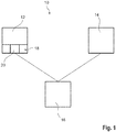
- a hybrid drive 10 of a motor vehicle which comprises an internal combustion engine 12 and an electric drive 14.
- control unit 16 is provided, which is coupled to both the internal combustion engine 12 and the electric drive 14, so that both data from the internal combustion engine 12 and data from the electric drive 14 can be detected via the control unit 16.
- control unit 16 is designed to control at least the electric drive 14.
- the internal combustion engine 12 comprises an injection system 18, which has a sensor 20, via which the injection system 18, the internal combustion engine 12, in particular the individual cylinders of the internal combustion engine 12, supplied To detect injection quantity.
- the data acquired by the sensor 20 are transmitted to the control unit 16, which is connected to the injection system 18.
- the control unit 16 Due to the data transmitted to it, the control unit 16 is able to detect a dynamic state of the internal combustion engine 12, on the basis of which the control unit 16 controls the electric drive 14 in such a way that the electric drive 14 relieves the internal combustion engine 12, provided that the control unit 16 has a dynamic State of the internal combustion engine 12 has detected, so an acceleration of the motor vehicle.
- control unit 16 determines the combustion air ratio, which will be present in the internal combustion engine 12, in particular in the respective cylinders of the internal combustion engine 12. About the combustion air ratio can be concluded that a dynamic state of the internal combustion engine 12.
- the combustion air ratio is determined before the burning of the fuel, so that the electric drive 14 can still be controlled so that it relieves the engine 12 in the correspondingly recognized dynamic state of the motor vehicle.
- the combustion air ratio is thus a measure of the dynamics.
- the dynamic state determination control unit 16 accesses the current injection quantity data transmitted from the sensor 20 of the injection system 18 to determine the difference between the current injection quantity of the engine 12 and a limiting injection amount, also referred to as the injection quantity difference can be. Due to this injection quantity difference can be concluded that the dynamic state.
- the dynamic state of the hybrid drive 10 or the motor vehicle due to a flushing gradient of the internal combustion engine 12 can be detected.
- the previous detection of the dynamic state via the injection quantity difference can be checked in this way.
- the purging gradient of the internal combustion engine 12 is an indicator of the charge cycle losses occurring in the internal combustion engine 12, in particular their change, which are also responsible for increased emissions.
- the purging gradient can be detected by the difference between an exhaust backpressure and a boost pressure.
- This difference can also be referred to as a pressure difference.
- the distributor of a turbocharger coupled to the internal combustion engine 12 closes, that is to say a flap or a valve. This leads to a rise in the exhaust backpressure, which sets an increased scavenging gradient.
- the hybrid drive 10 includes corresponding sensors that determine the present exhaust back pressure and / or the present boost pressure, so that it can be concluded that the present purging gradient over which the dynamic state is detected. Depending on the present exhaust gas back pressure, the purging gradient can thus be determined on the basis of a detected boost pressure deviation.
- the purging gradient can also be detected via the position of the turbine nozzle of the turbocharger.
- the position of the distributor that is to say that of the flap or of the valve, specifies how high the exhaust backpressure is that has an influence on the flushing gradient. Accordingly, the dynamic state can be determined thereby.
- the position of the distributor can also be detected by a corresponding sensor.
- the hybrid drive 10 may thus include a turbine turbocharger coupled to the engine 12.
- control unit 16 is configured such that it determines the difference between a current boost pressure and a desired value of the boost pressure.
- This difference which may also be referred to as boost pressure difference, is also suitable to serve as a measure of a dynamic state. Accordingly, the boost pressure difference can be used as an additional control variable and / or as a check, whether the dynamic state has been determined correctly due to the injection amount difference or the Spülge housess.
- control unit 16 is set up, the difference between a current exhaust gas recirculation rate and a desired value of
- the difference may be referred to as exhaust gas recirculation rate difference.
- This exhaust gas recirculation rate difference can also serve as a measure of the quality of the combustion of the internal combustion engine 12 or as a measure of the efficiency of the internal combustion engine 12. Due to the exhaust gas recirculation rate difference can thus be checked in an analogous manner, whether the detection of the dynamic state due to the injection quantity difference or the Spülge housess is correct. Further, the exhaust gas recirculation rate difference may be used as an additional control quantity.
- the injection quantity difference as well as the present scavenging gradient allows direct conclusions to be drawn regarding the nitrogen oxide or carbon dioxide emissions of the internal combustion engine 12 which occur in a dynamic state of the internal combustion engine 12, that is to say when the vehicle is accelerating. Due to this, the hybrid drive 10, in particular the control unit 16, is able to control the electric drive 14 so that the electric drive 14 relieves the engine 12 in the dynamic states in which the emissions are highest, that is, during acceleration of the motor vehicle ,
Landscapes
- Engineering & Computer Science (AREA)
- Chemical & Material Sciences (AREA)
- Combustion & Propulsion (AREA)
- Mechanical Engineering (AREA)
- Transportation (AREA)
- General Engineering & Computer Science (AREA)
- Automation & Control Theory (AREA)
- Hybrid Electric Vehicles (AREA)
- Output Control And Ontrol Of Special Type Engine (AREA)
Claims (10)
- Procédé de commande d'un entraînement hybride (10) d'un véhicule qui comporte un moteur à combustion interne (12) et un entraînement électrique (14) comprenant les étapes suivantes consistant à :a) identifier un état dynamique du moteur à combustion interne (12), en particulier une accélération du véhicule en déterminant un gradient de balayage du moteur à combustion interne (12), et/ou en déterminant le rapport d'air de combustion par la différence entre la quantité d'injection actuelle du moteur à combustion interne (12) et une quantité d'injection limite, en particulier en détectant une chute du rapport d'air de combustion,b) donner priorité à l'entraînement électrique (14) du moteur hybride (10) dans la mesure où un état dynamique a été identifié.
- Procédé conforme à la revendication 1,
caractérisé en ce qu'
on détermine la différence entre la pression de charge actuelle et une valeur de consigne de la pression de charge à partir de laquelle l'identification de l'état dynamique est contrôlée et/ou la différence est utilisée en tant que grandeur de commande. - Procédé conforme à l'une des revendications précédentes, caractérisé en ce qu'
on détecte la différence entre le taux de recirculation des gaz d'échappement actuel et une valeur de consigne du taux de recirculation des gaz d'échappement à partir de laquelle l'identification de l'état dynamique est contrôlé et/ou la différence est utilisée en tant que grandeur de commande. - Procédé conforme à l'une des revendications précédentes, caractérisé en ce qu'
on détecte la différence entre la contre-pression des gaz d'échappement et la pression de charge et/ou la position d'un appareil de guidage d'une turbine d'un turboréacteur de gaz d'échappement pour déterminer le gradient de balayage. - Système d'entraînement hybride (10) d'un véhicule comprenant un moteur à combustion interne (12), un entraînement électrique (14) ainsi qu'une unité de commande (16) qui est réalisée pour identifier un état dynamique du moteur à combustion interne (12) en déterminant un gradient de balayage et/ou en déterminant le rapport d'air de combustion par la différence entre la quantité d'injection actuelle du moteur à combustion interne (12) et une quantité d'injection limite, en particulier en détectant une chute du rapport d'air de combustion, l'unité de commande (16) étant réalisée pour donner priorité à l'entraînement électrique (14) dans la mesure où un état dynamique a été identifié.
- Système d'entraînement hybride (10) conforme à la revendication 5, caractérisé en ce qu'
il est prévu un système d'injection (18) du moteur à combustion interne (12) avec lequel est reliée l'unité de commande (16). - Système d'entraînement hybride (10) conforme à la revendication 6, caractérisé en ce que
le système d'injection (18) comporte au moins un capteur (20) qui détecte la quantité d'injection actuelle, la position d'un appareil de guidage, la contrepression des gaz d'échappement et/ou la pression de charge. - Système d'entraînement hybride (10) conforme à l'une des revendications 5 à 7,
caractérisé en ce que
l'unité de commande (16) est réalisée pour déterminer la différence entre la pression de charge actuelle et une valeur de consigne de la pression de charge. - Système d'entraînement hybride (10) conforme à l'une des revendications 5 à 8,
caractérisé en ce que
l'unité de commande (16) est réalisée pour déterminer la différence entre le taux de récupération des gaz d'échappement actuel et une valeur de consigne du taux de récupération des gaz d'échappement. - Système d'entraînement hybride (10) conforme à l'une des revendications 5 à 9,
caractérisé en ce que
l'unité de commande (16) est réalisée pour permettre de mettre en oeuvre un procédé conforme à l'une des revendications 1 à 4.
Applications Claiming Priority (1)
| Application Number | Priority Date | Filing Date | Title |
|---|---|---|---|
| DE102016223632.6A DE102016223632A1 (de) | 2016-11-29 | 2016-11-29 | Verfahren zur Steuerung eines Hybridantriebs eines Kraftfahrzeugs sowie Hybridantrieb eines Kraftfahrzeugs |
Publications (2)
| Publication Number | Publication Date |
|---|---|
| EP3326880A1 EP3326880A1 (fr) | 2018-05-30 |
| EP3326880B1 true EP3326880B1 (fr) | 2019-01-30 |
Family
ID=60083123
Family Applications (1)
| Application Number | Title | Priority Date | Filing Date |
|---|---|---|---|
| EP17195840.8A Active EP3326880B1 (fr) | 2016-11-29 | 2017-10-11 | Procédé de commande d'un entraînement hybride d'un véhicule automobile et entraînement hybride d'un véhicule automobile |
Country Status (2)
| Country | Link |
|---|---|
| EP (1) | EP3326880B1 (fr) |
| DE (1) | DE102016223632A1 (fr) |
Families Citing this family (1)
| Publication number | Priority date | Publication date | Assignee | Title |
|---|---|---|---|---|
| FR3103223B1 (fr) * | 2019-11-14 | 2021-10-08 | Continental Automotive | Procédé d’optimisation du gradient temporel de montée en pression dans un système d’injection d’un véhicule automobile hybride |
Family Cites Families (10)
| Publication number | Priority date | Publication date | Assignee | Title |
|---|---|---|---|---|
| DE19532128A1 (de) * | 1995-08-31 | 1997-03-06 | Clouth Gummiwerke Ag | Antriebssystem, insbesondere für ein Kraftfahrzeug, und Verfahren zum Betreiben desselben |
| US6823840B1 (en) * | 2003-08-21 | 2004-11-30 | General Motors Corporation | Manifold absolute pressure control system and method for a hybrid electric vehicle |
| JP3783712B2 (ja) * | 2003-12-03 | 2006-06-07 | トヨタ自動車株式会社 | ハイブリッド車両における内燃機関の制御方法 |
| DE102005008156A1 (de) * | 2005-02-23 | 2006-09-07 | Volkswagen Ag | Verfahren zum Betreiben eines Hybridantriebsystems und Vorrichtung zur Durchführung des Verfahrens |
| DE102005032670A1 (de) * | 2005-07-13 | 2007-02-01 | Iav Gmbh Ingenieurgesellschaft Auto Und Verkehr | Verfahren zur Steuerung der Antriebsleistungsverteilung in einem Kraftfahrzeug mit Hybridantrieb |
| DE102006044427A1 (de) * | 2006-09-21 | 2008-04-03 | Robert Bosch Gmbh | Verfahren zum Betreiben eines Hybridantriebs eines Kraftfahrzeugs |
| AT505717A2 (de) * | 2008-12-09 | 2009-03-15 | Avl List Gmbh | Verfahren zum betreiben eines antriebssystems |
| DE102011002541A1 (de) * | 2011-01-12 | 2012-07-12 | Zf Friedrichshafen Ag | Verfahren zum Betreiben eines Hybridantriebs sowie Steuerungseinrichtung eines Hybridantriebs |
| DE102012201111A1 (de) * | 2012-01-26 | 2013-08-01 | Zf Friedrichshafen Ag | Verfahren zum Betreiben eines Hybridantriebs und Steuerungseinrichtung |
| US9328674B2 (en) * | 2014-02-07 | 2016-05-03 | Cummins Inc. | Controls for performance optimization of internal combustion engine systems |
-
2016
- 2016-11-29 DE DE102016223632.6A patent/DE102016223632A1/de not_active Withdrawn
-
2017
- 2017-10-11 EP EP17195840.8A patent/EP3326880B1/fr active Active
Non-Patent Citations (1)
| Title |
|---|
| None * |
Also Published As
| Publication number | Publication date |
|---|---|
| DE102016223632A1 (de) | 2018-05-30 |
| EP3326880A1 (fr) | 2018-05-30 |
Similar Documents
| Publication | Publication Date | Title |
|---|---|---|
| DE102017220524B3 (de) | Abgasführung mit aktuierbarer Abgasturbine | |
| DE102013223723A1 (de) | Abgasrückführungsgerät für eine Kraftmaschine | |
| EP1582709B1 (fr) | Méthode de régénération d'un filtre à particule ainsi qu'un système d'échappement avec un filtre à particule | |
| WO2017097614A1 (fr) | Dosage de carburant pour le fonctionnement d'un moteur à combustion interne | |
| DE102013001043B3 (de) | Verfahren zum Betreiben einer Brennkraftmaschine sowie entsprechende Brennkraftmaschine | |
| EP4374052B1 (fr) | Procédé de fonctionnement d'un moteur à combustion interne d'un véhicule automobile et véhicule automobile | |
| EP2633175A1 (fr) | Procédé pour surveiller une adaptation d'un temps d'injection d'une soupape d'injection d'un moteur à combustion interne | |
| WO2016096607A1 (fr) | Procédé pour faire fonctionner un moteur à combustion interne | |
| EP2142783B1 (fr) | Procédé et dispositif de commande d'un moteur à combustion interne | |
| EP3326880A1 (fr) | Procédé de commande d'un entraînement hybride d'un véhicule automobile et entraînement hybride d'un véhicule automobile | |
| EP3688295B1 (fr) | Procédé permettant de faire fonctionner un dispositif d'entraînement et dispositif d'entraînement correspondant | |
| DE102018124922B4 (de) | Diesel-Hybrid Antriebstechnik mit Harnstoff-freier NOx Umwandlung | |
| EP1306537A2 (fr) | Méthode et dispositif de commande d'un moteur à combustion interne | |
| EP1826378A2 (fr) | Procédé de fonctionnement pour moteur thermique, en particulier d'automobile | |
| WO2017055121A1 (fr) | Procédé de fonctionnement d'un moteur à combustion interne pour un véhicule automobile et système pour un moteur à combustion interne | |
| DE102020100434A1 (de) | Verfahren zum Betreiben einer Antriebseinrichtung für ein Kraftfahrzeug sowie entsprechende Antriebseinrichtung | |
| DE102007012309B4 (de) | Verfahren und Vorrichtung zur Erkennung der Kraftstoffqualität bei einer Brennkraftmaschine | |
| EP1966468B1 (fr) | Procede et dispositif de regeneration d'un systeme de traitement de gaz d'echappement | |
| DE102011013392A1 (de) | Verfahren zur Regelung eines Verbrennungsmotors | |
| EP1029168B1 (fr) | Procede d'exploitation d'un moteur a combustion interne, en particulier, de vehicule automobile | |
| DE4425938B4 (de) | Traktionsregelungssystem für Motorfahrzeuge | |
| DE102010011240A1 (de) | Drosselklappensteuerung für einen Verbrennungsmotor | |
| EP2173991B1 (fr) | Procédé et dispositif de fonctionnement d'un moteur à combustion interne | |
| DE102018125820A1 (de) | Verfahren zum Betreiben eines Antriebsstranges eines Kraftfahrzeugs | |
| DE102006060308A1 (de) | Verfahren zum Betreiben einer Antriebseinheit |
Legal Events
| Date | Code | Title | Description |
|---|---|---|---|
| PUAI | Public reference made under article 153(3) epc to a published international application that has entered the european phase |
Free format text: ORIGINAL CODE: 0009012 |
|
| STAA | Information on the status of an ep patent application or granted ep patent |
Free format text: STATUS: THE APPLICATION HAS BEEN PUBLISHED |
|
| AK | Designated contracting states |
Kind code of ref document: A1 Designated state(s): AL AT BE BG CH CY CZ DE DK EE ES FI FR GB GR HR HU IE IS IT LI LT LU LV MC MK MT NL NO PL PT RO RS SE SI SK SM TR |
|
| AX | Request for extension of the european patent |
Extension state: BA ME |
|
| STAA | Information on the status of an ep patent application or granted ep patent |
Free format text: STATUS: REQUEST FOR EXAMINATION WAS MADE |
|
| 17P | Request for examination filed |
Effective date: 20180810 |
|
| RBV | Designated contracting states (corrected) |
Designated state(s): AL AT BE BG CH CY CZ DE DK EE ES FI FR GB GR HR HU IE IS IT LI LT LU LV MC MK MT NL NO PL PT RO RS SE SI SK SM TR |
|
| REG | Reference to a national code |
Ref country code: DE Ref legal event code: R079 Ref document number: 502017000716 Country of ref document: DE Free format text: PREVIOUS MAIN CLASS: B60W0010060000 Ipc: B60W0020190000 |
|
| GRAP | Despatch of communication of intention to grant a patent |
Free format text: ORIGINAL CODE: EPIDOSNIGR1 |
|
| STAA | Information on the status of an ep patent application or granted ep patent |
Free format text: STATUS: GRANT OF PATENT IS INTENDED |
|
| RIC1 | Information provided on ipc code assigned before grant |
Ipc: B60W 10/06 20060101ALI20180926BHEP Ipc: F02D 41/14 20060101ALI20180926BHEP Ipc: F02D 41/00 20060101ALI20180926BHEP Ipc: B60W 20/16 20160101ALI20180926BHEP Ipc: B60W 10/08 20060101ALI20180926BHEP Ipc: F02D 41/04 20060101ALI20180926BHEP Ipc: B60W 20/19 20160101AFI20180926BHEP |
|
| INTG | Intention to grant announced |
Effective date: 20181017 |
|
| GRAS | Grant fee paid |
Free format text: ORIGINAL CODE: EPIDOSNIGR3 |
|
| GRAA | (expected) grant |
Free format text: ORIGINAL CODE: 0009210 |
|
| STAA | Information on the status of an ep patent application or granted ep patent |
Free format text: STATUS: THE PATENT HAS BEEN GRANTED |
|
| AK | Designated contracting states |
Kind code of ref document: B1 Designated state(s): AL AT BE BG CH CY CZ DE DK EE ES FI FR GB GR HR HU IE IS IT LI LT LU LV MC MK MT NL NO PL PT RO RS SE SI SK SM TR |
|
| REG | Reference to a national code |
Ref country code: GB Ref legal event code: FG4D Free format text: NOT ENGLISH |
|
| REG | Reference to a national code |
Ref country code: CH Ref legal event code: EP |
|
| REG | Reference to a national code |
Ref country code: AT Ref legal event code: REF Ref document number: 1093011 Country of ref document: AT Kind code of ref document: T Effective date: 20190215 |
|
| REG | Reference to a national code |
Ref country code: IE Ref legal event code: FG4D Free format text: LANGUAGE OF EP DOCUMENT: GERMAN |
|
| REG | Reference to a national code |
Ref country code: DE Ref legal event code: R096 Ref document number: 502017000716 Country of ref document: DE |
|
| REG | Reference to a national code |
Ref country code: NL Ref legal event code: MP Effective date: 20190130 |
|
| REG | Reference to a national code |
Ref country code: LT Ref legal event code: MG4D |
|
| PG25 | Lapsed in a contracting state [announced via postgrant information from national office to epo] |
Ref country code: ES Free format text: LAPSE BECAUSE OF FAILURE TO SUBMIT A TRANSLATION OF THE DESCRIPTION OR TO PAY THE FEE WITHIN THE PRESCRIBED TIME-LIMIT Effective date: 20190130 Ref country code: FI Free format text: LAPSE BECAUSE OF FAILURE TO SUBMIT A TRANSLATION OF THE DESCRIPTION OR TO PAY THE FEE WITHIN THE PRESCRIBED TIME-LIMIT Effective date: 20190130 Ref country code: NL Free format text: LAPSE BECAUSE OF FAILURE TO SUBMIT A TRANSLATION OF THE DESCRIPTION OR TO PAY THE FEE WITHIN THE PRESCRIBED TIME-LIMIT Effective date: 20190130 Ref country code: PT Free format text: LAPSE BECAUSE OF FAILURE TO SUBMIT A TRANSLATION OF THE DESCRIPTION OR TO PAY THE FEE WITHIN THE PRESCRIBED TIME-LIMIT Effective date: 20190530 Ref country code: SE Free format text: LAPSE BECAUSE OF FAILURE TO SUBMIT A TRANSLATION OF THE DESCRIPTION OR TO PAY THE FEE WITHIN THE PRESCRIBED TIME-LIMIT Effective date: 20190130 Ref country code: NO Free format text: LAPSE BECAUSE OF FAILURE TO SUBMIT A TRANSLATION OF THE DESCRIPTION OR TO PAY THE FEE WITHIN THE PRESCRIBED TIME-LIMIT Effective date: 20190430 Ref country code: LT Free format text: LAPSE BECAUSE OF FAILURE TO SUBMIT A TRANSLATION OF THE DESCRIPTION OR TO PAY THE FEE WITHIN THE PRESCRIBED TIME-LIMIT Effective date: 20190130 Ref country code: PL Free format text: LAPSE BECAUSE OF FAILURE TO SUBMIT A TRANSLATION OF THE DESCRIPTION OR TO PAY THE FEE WITHIN THE PRESCRIBED TIME-LIMIT Effective date: 20190130 |
|
| PG25 | Lapsed in a contracting state [announced via postgrant information from national office to epo] |
Ref country code: IS Free format text: LAPSE BECAUSE OF FAILURE TO SUBMIT A TRANSLATION OF THE DESCRIPTION OR TO PAY THE FEE WITHIN THE PRESCRIBED TIME-LIMIT Effective date: 20190530 Ref country code: RS Free format text: LAPSE BECAUSE OF FAILURE TO SUBMIT A TRANSLATION OF THE DESCRIPTION OR TO PAY THE FEE WITHIN THE PRESCRIBED TIME-LIMIT Effective date: 20190130 Ref country code: BG Free format text: LAPSE BECAUSE OF FAILURE TO SUBMIT A TRANSLATION OF THE DESCRIPTION OR TO PAY THE FEE WITHIN THE PRESCRIBED TIME-LIMIT Effective date: 20190430 Ref country code: LV Free format text: LAPSE BECAUSE OF FAILURE TO SUBMIT A TRANSLATION OF THE DESCRIPTION OR TO PAY THE FEE WITHIN THE PRESCRIBED TIME-LIMIT Effective date: 20190130 Ref country code: HR Free format text: LAPSE BECAUSE OF FAILURE TO SUBMIT A TRANSLATION OF THE DESCRIPTION OR TO PAY THE FEE WITHIN THE PRESCRIBED TIME-LIMIT Effective date: 20190130 Ref country code: GR Free format text: LAPSE BECAUSE OF FAILURE TO SUBMIT A TRANSLATION OF THE DESCRIPTION OR TO PAY THE FEE WITHIN THE PRESCRIBED TIME-LIMIT Effective date: 20190501 |
|
| PG25 | Lapsed in a contracting state [announced via postgrant information from national office to epo] |
Ref country code: CZ Free format text: LAPSE BECAUSE OF FAILURE TO SUBMIT A TRANSLATION OF THE DESCRIPTION OR TO PAY THE FEE WITHIN THE PRESCRIBED TIME-LIMIT Effective date: 20190130 Ref country code: AL Free format text: LAPSE BECAUSE OF FAILURE TO SUBMIT A TRANSLATION OF THE DESCRIPTION OR TO PAY THE FEE WITHIN THE PRESCRIBED TIME-LIMIT Effective date: 20190130 Ref country code: SK Free format text: LAPSE BECAUSE OF FAILURE TO SUBMIT A TRANSLATION OF THE DESCRIPTION OR TO PAY THE FEE WITHIN THE PRESCRIBED TIME-LIMIT Effective date: 20190130 Ref country code: EE Free format text: LAPSE BECAUSE OF FAILURE TO SUBMIT A TRANSLATION OF THE DESCRIPTION OR TO PAY THE FEE WITHIN THE PRESCRIBED TIME-LIMIT Effective date: 20190130 Ref country code: DK Free format text: LAPSE BECAUSE OF FAILURE TO SUBMIT A TRANSLATION OF THE DESCRIPTION OR TO PAY THE FEE WITHIN THE PRESCRIBED TIME-LIMIT Effective date: 20190130 Ref country code: RO Free format text: LAPSE BECAUSE OF FAILURE TO SUBMIT A TRANSLATION OF THE DESCRIPTION OR TO PAY THE FEE WITHIN THE PRESCRIBED TIME-LIMIT Effective date: 20190130 |
|
| REG | Reference to a national code |
Ref country code: DE Ref legal event code: R097 Ref document number: 502017000716 Country of ref document: DE |
|
| PG25 | Lapsed in a contracting state [announced via postgrant information from national office to epo] |
Ref country code: SM Free format text: LAPSE BECAUSE OF FAILURE TO SUBMIT A TRANSLATION OF THE DESCRIPTION OR TO PAY THE FEE WITHIN THE PRESCRIBED TIME-LIMIT Effective date: 20190130 |
|
| PLBE | No opposition filed within time limit |
Free format text: ORIGINAL CODE: 0009261 |
|
| STAA | Information on the status of an ep patent application or granted ep patent |
Free format text: STATUS: NO OPPOSITION FILED WITHIN TIME LIMIT |
|
| 26N | No opposition filed |
Effective date: 20191031 |
|
| PG25 | Lapsed in a contracting state [announced via postgrant information from national office to epo] |
Ref country code: TR Free format text: LAPSE BECAUSE OF FAILURE TO SUBMIT A TRANSLATION OF THE DESCRIPTION OR TO PAY THE FEE WITHIN THE PRESCRIBED TIME-LIMIT Effective date: 20190130 |
|
| PG25 | Lapsed in a contracting state [announced via postgrant information from national office to epo] |
Ref country code: MC Free format text: LAPSE BECAUSE OF FAILURE TO SUBMIT A TRANSLATION OF THE DESCRIPTION OR TO PAY THE FEE WITHIN THE PRESCRIBED TIME-LIMIT Effective date: 20190130 |
|
| PG25 | Lapsed in a contracting state [announced via postgrant information from national office to epo] |
Ref country code: LU Free format text: LAPSE BECAUSE OF NON-PAYMENT OF DUE FEES Effective date: 20191011 |
|
| REG | Reference to a national code |
Ref country code: BE Ref legal event code: MM Effective date: 20191031 |
|
| PG25 | Lapsed in a contracting state [announced via postgrant information from national office to epo] |
Ref country code: BE Free format text: LAPSE BECAUSE OF NON-PAYMENT OF DUE FEES Effective date: 20191031 |
|
| PG25 | Lapsed in a contracting state [announced via postgrant information from national office to epo] |
Ref country code: IE Free format text: LAPSE BECAUSE OF NON-PAYMENT OF DUE FEES Effective date: 20191011 |
|
| PG25 | Lapsed in a contracting state [announced via postgrant information from national office to epo] |
Ref country code: CY Free format text: LAPSE BECAUSE OF FAILURE TO SUBMIT A TRANSLATION OF THE DESCRIPTION OR TO PAY THE FEE WITHIN THE PRESCRIBED TIME-LIMIT Effective date: 20190130 |
|
| REG | Reference to a national code |
Ref country code: CH Ref legal event code: PL |
|
| PG25 | Lapsed in a contracting state [announced via postgrant information from national office to epo] |
Ref country code: CH Free format text: LAPSE BECAUSE OF FAILURE TO SUBMIT A TRANSLATION OF THE DESCRIPTION OR TO PAY THE FEE WITHIN THE PRESCRIBED TIME-LIMIT Effective date: 20201031 Ref country code: LI Free format text: LAPSE BECAUSE OF FAILURE TO SUBMIT A TRANSLATION OF THE DESCRIPTION OR TO PAY THE FEE WITHIN THE PRESCRIBED TIME-LIMIT Effective date: 20201031 |
|
| PG25 | Lapsed in a contracting state [announced via postgrant information from national office to epo] |
Ref country code: HU Free format text: LAPSE BECAUSE OF FAILURE TO SUBMIT A TRANSLATION OF THE DESCRIPTION OR TO PAY THE FEE WITHIN THE PRESCRIBED TIME-LIMIT; INVALID AB INITIO Effective date: 20171011 Ref country code: MT Free format text: LAPSE BECAUSE OF FAILURE TO SUBMIT A TRANSLATION OF THE DESCRIPTION OR TO PAY THE FEE WITHIN THE PRESCRIBED TIME-LIMIT Effective date: 20190130 |
|
| PG25 | Lapsed in a contracting state [announced via postgrant information from national office to epo] |
Ref country code: SI Free format text: LAPSE BECAUSE OF FAILURE TO SUBMIT A TRANSLATION OF THE DESCRIPTION OR TO PAY THE FEE WITHIN THE PRESCRIBED TIME-LIMIT Effective date: 20190130 |
|
| PG25 | Lapsed in a contracting state [announced via postgrant information from national office to epo] |
Ref country code: MK Free format text: LAPSE BECAUSE OF FAILURE TO SUBMIT A TRANSLATION OF THE DESCRIPTION OR TO PAY THE FEE WITHIN THE PRESCRIBED TIME-LIMIT Effective date: 20190130 |
|
| P01 | Opt-out of the competence of the unified patent court (upc) registered |
Effective date: 20230502 |
|
| REG | Reference to a national code |
Ref country code: AT Ref legal event code: MM01 Ref document number: 1093011 Country of ref document: AT Kind code of ref document: T Effective date: 20221011 |
|
| PG25 | Lapsed in a contracting state [announced via postgrant information from national office to epo] |
Ref country code: AT Free format text: LAPSE BECAUSE OF NON-PAYMENT OF DUE FEES Effective date: 20221011 |
|
| PGFP | Annual fee paid to national office [announced via postgrant information from national office to epo] |
Ref country code: DE Payment date: 20251021 Year of fee payment: 9 |
|
| PGFP | Annual fee paid to national office [announced via postgrant information from national office to epo] |
Ref country code: GB Payment date: 20251024 Year of fee payment: 9 |
|
| PGFP | Annual fee paid to national office [announced via postgrant information from national office to epo] |
Ref country code: IT Payment date: 20251031 Year of fee payment: 9 |
|
| PGFP | Annual fee paid to national office [announced via postgrant information from national office to epo] |
Ref country code: FR Payment date: 20251024 Year of fee payment: 9 |