EP3327191B1 - Fabrication de tissus non tissés comprenant un composant - Google Patents
Fabrication de tissus non tissés comprenant un composant Download PDFInfo
- Publication number
- EP3327191B1 EP3327191B1 EP17203193.2A EP17203193A EP3327191B1 EP 3327191 B1 EP3327191 B1 EP 3327191B1 EP 17203193 A EP17203193 A EP 17203193A EP 3327191 B1 EP3327191 B1 EP 3327191B1
- Authority
- EP
- European Patent Office
- Prior art keywords
- fibers
- substrate
- woven fabric
- component
- onto
- Prior art date
- Legal status (The legal status is an assumption and is not a legal conclusion. Google has not performed a legal analysis and makes no representation as to the accuracy of the status listed.)
- Active
Links
Images



Classifications
-
- D—TEXTILES; PAPER
- D01—NATURAL OR MAN-MADE THREADS OR FIBRES; SPINNING
- D01D—MECHANICAL METHODS OR APPARATUS IN THE MANUFACTURE OF ARTIFICIAL FILAMENTS, THREADS, FIBRES, BRISTLES OR RIBBONS
- D01D11/00—Other features of manufacture
- D01D11/06—Coating with spinning solutions or melts
-
- A—HUMAN NECESSITIES
- A43—FOOTWEAR
- A43B—CHARACTERISTIC FEATURES OF FOOTWEAR; PARTS OF FOOTWEAR
- A43B1/00—Footwear characterised by the material
- A43B1/0063—Footwear characterised by the material made at least partially of material that can be recycled
-
- A—HUMAN NECESSITIES
- A43—FOOTWEAR
- A43B—CHARACTERISTIC FEATURES OF FOOTWEAR; PARTS OF FOOTWEAR
- A43B23/00—Uppers; Boot legs; Stiffeners; Other single parts of footwear
- A43B23/02—Uppers; Boot legs
- A43B23/0205—Uppers; Boot legs characterised by the material
-
- A—HUMAN NECESSITIES
- A43—FOOTWEAR
- A43B—CHARACTERISTIC FEATURES OF FOOTWEAR; PARTS OF FOOTWEAR
- A43B23/00—Uppers; Boot legs; Stiffeners; Other single parts of footwear
- A43B23/02—Uppers; Boot legs
- A43B23/0205—Uppers; Boot legs characterised by the material
- A43B23/0215—Plastics or artificial leather
-
- A—HUMAN NECESSITIES
- A43—FOOTWEAR
- A43B—CHARACTERISTIC FEATURES OF FOOTWEAR; PARTS OF FOOTWEAR
- A43B23/00—Uppers; Boot legs; Stiffeners; Other single parts of footwear
- A43B23/02—Uppers; Boot legs
- A43B23/0205—Uppers; Boot legs characterised by the material
- A43B23/0225—Composite materials, e.g. material with a matrix
-
- A—HUMAN NECESSITIES
- A43—FOOTWEAR
- A43B—CHARACTERISTIC FEATURES OF FOOTWEAR; PARTS OF FOOTWEAR
- A43B23/00—Uppers; Boot legs; Stiffeners; Other single parts of footwear
- A43B23/02—Uppers; Boot legs
- A43B23/0245—Uppers; Boot legs characterised by the constructive form
- A43B23/0255—Uppers; Boot legs characterised by the constructive form assembled by gluing or thermo bonding
-
- A—HUMAN NECESSITIES
- A43—FOOTWEAR
- A43B—CHARACTERISTIC FEATURES OF FOOTWEAR; PARTS OF FOOTWEAR
- A43B23/00—Uppers; Boot legs; Stiffeners; Other single parts of footwear
- A43B23/02—Uppers; Boot legs
- A43B23/04—Uppers made of one piece; Uppers with inserted gussets
- A43B23/042—Uppers made of one piece
-
- A—HUMAN NECESSITIES
- A43—FOOTWEAR
- A43D—MACHINES, TOOLS, EQUIPMENT OR METHODS FOR MANUFACTURING OR REPAIRING FOOTWEAR
- A43D3/00—Lasts
- A43D3/02—Lasts for making or repairing shoes
-
- B—PERFORMING OPERATIONS; TRANSPORTING
- B29—WORKING OF PLASTICS; WORKING OF SUBSTANCES IN A PLASTIC STATE IN GENERAL
- B29D—PRODUCING PARTICULAR ARTICLES FROM PLASTICS OR FROM SUBSTANCES IN A PLASTIC STATE
- B29D35/00—Producing footwear
- B29D35/12—Producing parts thereof, e.g. soles, heels, uppers, by a moulding technique
- B29D35/126—Uppers
-
- B—PERFORMING OPERATIONS; TRANSPORTING
- B29—WORKING OF PLASTICS; WORKING OF SUBSTANCES IN A PLASTIC STATE IN GENERAL
- B29D—PRODUCING PARTICULAR ARTICLES FROM PLASTICS OR FROM SUBSTANCES IN A PLASTIC STATE
- B29D35/00—Producing footwear
- B29D35/12—Producing parts thereof, e.g. soles, heels, uppers, by a moulding technique
- B29D35/128—Moulds or apparatus therefor
-
- B—PERFORMING OPERATIONS; TRANSPORTING
- B29—WORKING OF PLASTICS; WORKING OF SUBSTANCES IN A PLASTIC STATE IN GENERAL
- B29D—PRODUCING PARTICULAR ARTICLES FROM PLASTICS OR FROM SUBSTANCES IN A PLASTIC STATE
- B29D35/00—Producing footwear
- B29D35/12—Producing parts thereof, e.g. soles, heels, uppers, by a moulding technique
- B29D35/14—Multilayered parts
- B29D35/146—Uppers
-
- B—PERFORMING OPERATIONS; TRANSPORTING
- B29—WORKING OF PLASTICS; WORKING OF SUBSTANCES IN A PLASTIC STATE IN GENERAL
- B29D—PRODUCING PARTICULAR ARTICLES FROM PLASTICS OR FROM SUBSTANCES IN A PLASTIC STATE
- B29D35/00—Producing footwear
- B29D35/12—Producing parts thereof, e.g. soles, heels, uppers, by a moulding technique
- B29D35/14—Multilayered parts
- B29D35/148—Moulds or apparatus therefor
-
- D—TEXTILES; PAPER
- D01—NATURAL OR MAN-MADE THREADS OR FIBRES; SPINNING
- D01D—MECHANICAL METHODS OR APPARATUS IN THE MANUFACTURE OF ARTIFICIAL FILAMENTS, THREADS, FIBRES, BRISTLES OR RIBBONS
- D01D5/00—Formation of filaments, threads, or the like
- D01D5/08—Melt spinning methods
- D01D5/098—Melt spinning methods with simultaneous stretching
- D01D5/0985—Melt spinning methods with simultaneous stretching by means of a flowing gas (e.g. melt-blowing)
-
- D—TEXTILES; PAPER
- D04—BRAIDING; LACE-MAKING; KNITTING; TRIMMINGS; NON-WOVEN FABRICS
- D04H—MAKING TEXTILE FABRICS, e.g. FROM FIBRES OR FILAMENTARY MATERIAL; FABRICS MADE BY SUCH PROCESSES OR APPARATUS, e.g. FELTS, NON-WOVEN FABRICS; COTTON-WOOL; WADDING ; NON-WOVEN FABRICS FROM STAPLE FIBRES, FILAMENTS OR YARNS, BONDED WITH AT LEAST ONE WEB-LIKE MATERIAL DURING THEIR CONSOLIDATION
- D04H1/00—Non-woven fabrics formed wholly or mainly of staple fibres or like relatively short fibres
- D04H1/40—Non-woven fabrics formed wholly or mainly of staple fibres or like relatively short fibres from fleeces or layers composed of fibres without existing or potential cohesive properties
- D04H1/42—Non-woven fabrics formed wholly or mainly of staple fibres or like relatively short fibres from fleeces or layers composed of fibres without existing or potential cohesive properties characterised by the use of certain kinds of fibres insofar as this use has no preponderant influence on the consolidation of the fleece
- D04H1/4374—Non-woven fabrics formed wholly or mainly of staple fibres or like relatively short fibres from fleeces or layers composed of fibres without existing or potential cohesive properties characterised by the use of certain kinds of fibres insofar as this use has no preponderant influence on the consolidation of the fleece using different kinds of webs, e.g. by layering webs
-
- D—TEXTILES; PAPER
- D04—BRAIDING; LACE-MAKING; KNITTING; TRIMMINGS; NON-WOVEN FABRICS
- D04H—MAKING TEXTILE FABRICS, e.g. FROM FIBRES OR FILAMENTARY MATERIAL; FABRICS MADE BY SUCH PROCESSES OR APPARATUS, e.g. FELTS, NON-WOVEN FABRICS; COTTON-WOOL; WADDING ; NON-WOVEN FABRICS FROM STAPLE FIBRES, FILAMENTS OR YARNS, BONDED WITH AT LEAST ONE WEB-LIKE MATERIAL DURING THEIR CONSOLIDATION
- D04H1/00—Non-woven fabrics formed wholly or mainly of staple fibres or like relatively short fibres
- D04H1/40—Non-woven fabrics formed wholly or mainly of staple fibres or like relatively short fibres from fleeces or layers composed of fibres without existing or potential cohesive properties
- D04H1/54—Non-woven fabrics formed wholly or mainly of staple fibres or like relatively short fibres from fleeces or layers composed of fibres without existing or potential cohesive properties by welding together the fibres, e.g. by partially melting or dissolving
- D04H1/56—Non-woven fabrics formed wholly or mainly of staple fibres or like relatively short fibres from fleeces or layers composed of fibres without existing or potential cohesive properties by welding together the fibres, e.g. by partially melting or dissolving in association with fibre formation, e.g. immediately following extrusion of staple fibres
-
- D—TEXTILES; PAPER
- D04—BRAIDING; LACE-MAKING; KNITTING; TRIMMINGS; NON-WOVEN FABRICS
- D04H—MAKING TEXTILE FABRICS, e.g. FROM FIBRES OR FILAMENTARY MATERIAL; FABRICS MADE BY SUCH PROCESSES OR APPARATUS, e.g. FELTS, NON-WOVEN FABRICS; COTTON-WOOL; WADDING ; NON-WOVEN FABRICS FROM STAPLE FIBRES, FILAMENTS OR YARNS, BONDED WITH AT LEAST ONE WEB-LIKE MATERIAL DURING THEIR CONSOLIDATION
- D04H1/00—Non-woven fabrics formed wholly or mainly of staple fibres or like relatively short fibres
- D04H1/70—Non-woven fabrics formed wholly or mainly of staple fibres or like relatively short fibres characterised by the method of forming fleeces or layers, e.g. reorientation of fibres
- D04H1/76—Non-woven fabrics formed wholly or mainly of staple fibres or like relatively short fibres characterised by the method of forming fleeces or layers, e.g. reorientation of fibres otherwise than in a plane, e.g. in a tubular way
-
- D—TEXTILES; PAPER
- D04—BRAIDING; LACE-MAKING; KNITTING; TRIMMINGS; NON-WOVEN FABRICS
- D04H—MAKING TEXTILE FABRICS, e.g. FROM FIBRES OR FILAMENTARY MATERIAL; FABRICS MADE BY SUCH PROCESSES OR APPARATUS, e.g. FELTS, NON-WOVEN FABRICS; COTTON-WOOL; WADDING ; NON-WOVEN FABRICS FROM STAPLE FIBRES, FILAMENTS OR YARNS, BONDED WITH AT LEAST ONE WEB-LIKE MATERIAL DURING THEIR CONSOLIDATION
- D04H13/00—Other non-woven fabrics
-
- D—TEXTILES; PAPER
- D04—BRAIDING; LACE-MAKING; KNITTING; TRIMMINGS; NON-WOVEN FABRICS
- D04H—MAKING TEXTILE FABRICS, e.g. FROM FIBRES OR FILAMENTARY MATERIAL; FABRICS MADE BY SUCH PROCESSES OR APPARATUS, e.g. FELTS, NON-WOVEN FABRICS; COTTON-WOOL; WADDING ; NON-WOVEN FABRICS FROM STAPLE FIBRES, FILAMENTS OR YARNS, BONDED WITH AT LEAST ONE WEB-LIKE MATERIAL DURING THEIR CONSOLIDATION
- D04H3/00—Non-woven fabrics formed wholly or mainly of yarns or like filamentary material of substantial length
- D04H3/02—Non-woven fabrics formed wholly or mainly of yarns or like filamentary material of substantial length characterised by the method of forming fleeces or layers, e.g. reorientation of yarns or filaments
- D04H3/07—Non-woven fabrics formed wholly or mainly of yarns or like filamentary material of substantial length characterised by the method of forming fleeces or layers, e.g. reorientation of yarns or filaments otherwise than in a plane, e.g. in a tubular way
-
- D—TEXTILES; PAPER
- D04—BRAIDING; LACE-MAKING; KNITTING; TRIMMINGS; NON-WOVEN FABRICS
- D04H—MAKING TEXTILE FABRICS, e.g. FROM FIBRES OR FILAMENTARY MATERIAL; FABRICS MADE BY SUCH PROCESSES OR APPARATUS, e.g. FELTS, NON-WOVEN FABRICS; COTTON-WOOL; WADDING ; NON-WOVEN FABRICS FROM STAPLE FIBRES, FILAMENTS OR YARNS, BONDED WITH AT LEAST ONE WEB-LIKE MATERIAL DURING THEIR CONSOLIDATION
- D04H3/00—Non-woven fabrics formed wholly or mainly of yarns or like filamentary material of substantial length
- D04H3/08—Non-woven fabrics formed wholly or mainly of yarns or like filamentary material of substantial length characterised by the method of strengthening or consolidating
- D04H3/16—Non-woven fabrics formed wholly or mainly of yarns or like filamentary material of substantial length characterised by the method of strengthening or consolidating with bonds between thermoplastic filaments produced in association with filament formation, e.g. immediately following extrusion
-
- D—TEXTILES; PAPER
- D10—INDEXING SCHEME ASSOCIATED WITH SUBLASSES OF SECTION D, RELATING TO TEXTILES
- D10B—INDEXING SCHEME ASSOCIATED WITH SUBLASSES OF SECTION D, RELATING TO TEXTILES
- D10B2331/00—Fibres made from polymers obtained otherwise than by reactions only involving carbon-to-carbon unsaturated bonds, e.g. polycondensation products
- D10B2331/10—Fibres made from polymers obtained otherwise than by reactions only involving carbon-to-carbon unsaturated bonds, e.g. polycondensation products polyurethanes
-
- D—TEXTILES; PAPER
- D10—INDEXING SCHEME ASSOCIATED WITH SUBLASSES OF SECTION D, RELATING TO TEXTILES
- D10B—INDEXING SCHEME ASSOCIATED WITH SUBLASSES OF SECTION D, RELATING TO TEXTILES
- D10B2501/00—Wearing apparel
- D10B2501/04—Outerwear; Protective garments
- D10B2501/043—Footwear
-
- Y—GENERAL TAGGING OF NEW TECHNOLOGICAL DEVELOPMENTS; GENERAL TAGGING OF CROSS-SECTIONAL TECHNOLOGIES SPANNING OVER SEVERAL SECTIONS OF THE IPC; TECHNICAL SUBJECTS COVERED BY FORMER USPC CROSS-REFERENCE ART COLLECTIONS [XRACs] AND DIGESTS
- Y02—TECHNOLOGIES OR APPLICATIONS FOR MITIGATION OR ADAPTATION AGAINST CLIMATE CHANGE
- Y02P—CLIMATE CHANGE MITIGATION TECHNOLOGIES IN THE PRODUCTION OR PROCESSING OF GOODS
- Y02P70/00—Climate change mitigation technologies in the production process for final industrial or consumer products
- Y02P70/50—Manufacturing or production processes characterised by the final manufactured product
- Y02P70/62—Manufacturing or production processes characterised by the final manufactured product related technologies for production or treatment of textile or flexible materials or products thereof, including footwear
Definitions
- the present invention relates to a method of manufacturing a three-dimensional non-woven fabric and to a non-woven fabric obtained by such a method.
- Non-woven fabrics are made from fibers bonded together by chemical, mechanical, heat or solvent treatment. Different than woven or knitted fabrics, the fibers in non-woven fabrics are not present as yarns which are mechanically fixed by a mesh or loop structure. Non-woven fabrics are used for wide variety of products and articles including shoes, apparel and sports equipment.
- US 2006/0276095 A1 relates to an article of footwear of non-woven material and a method of manufacturing the same.
- WO 2016/099687 A1 is directed to a non-woven material, method of making the same, and articles incorporating the non-woven material.
- WO 2014/167420 A2 relates to an apparatus for producing non-woven product in a non-industrial environment.
- GB 1 363 675 is directed to a method of making shoes.
- EP 2 412 856 B1 relates to an apparatus for fabricating a three-dimensional non-woven fabric structure.
- US 2006276095 A1 concerns a method of forming a portion of an article of footwear that includes the steps of providing a last having an exterior surface, extruding a plurality of polymeric fibers, projecting a stream of the extruded polymeric fibers onto the last to form a mat having the shape of the exterior of the last, and subjecting the mat to heat and pressure in a mold.
- US 2013320584 A1 concerns a method of manufacturing a textured element that may include (a) collecting a plurality of filaments upon a textured surface to form a non-woven textile and (b) separating the non-woven textile from the textured surface.
- US 2013285294 A1 concerns a method of making a double-sided embossed non-woven fabric that includes: forming a stack of semi-molten fibers on a screen assembly, the screen assembly including a first layer structure that has a plurality of suction holes arranged into a first pattern, and a second layer structure that is disposed on the first layer structure and that has a plurality of elements arranged into a second pattern; and embossing the stack of the semi-molten fibers on the screen assembly by suctioning the stack of the semi-molten fibers using a suctioning device such that the stack of the semi-molten fibers is drawn into the holes to wrap the elements.
- US 4741941 A concerns a nonwoven web and method of making including interbonded thermoplastic fibers in an array of hollow projections extending outwardly from at least one surface of said web.
- WO 2016077221 A1 is directed to production of constructs of footwear and components thereof by jet extrusion.
- the non-woven fabrics in such articles is often not very rigid and resistant.
- this problem is solved by a method of manufacturing a non-woven fabric according to the subject-matter of claim 1.
- the substrate is air permeable in at least a portion of its surface and the method comprises the step of applying a pressure differential to the air permeable portion. More particularly, the pressure differential is applied, so that the fibers transferred onto the substrate are attracted by the pressure differential. This allows to compact the fibers together to obtain a more dense non-woven fabric. On the other hand, the fibers are not compacted in those areas of the surface of the substrate not being air permeable for example. Thus, it is possible to provide a non-woven fabric with padded zones (non-compacted fibers) and areas with increased structural strength (compacted fibers).
- Suction provided by a pressure differential is especially advantageous with concave three-dimensional substrates because the fibers otherwise have a tendency to bridge across the concave portions of such a shape.
- a pressure differential and in some embodiments with a higher pressure differential applied in the concave portions of the substrate, the fibers are sucked in the concave portions, such that they conform to the shape of the substrate.
- the pressure differential is varied across the surface of the substrate.
- the fibers may be compacted to a different degree across the non-woven fabric.
- the thickness of the non-woven fabric may be locally varied.
- a variation of the pressure differential may influence the trajectories of the fibers to guide the fibers to specific locations on the substrate.
- the fibers may be guided to concave areas (or recesses) where the fibers may accumulate to create, for example, a padding portion.
- the substrate may comprise different air permeable areas with different local air permeability averages. For example, some portions may be non-permeable, while at least one other portion may be air permeable.
- the air permeable portion comprises a plurality of holes. This allows to vary the air permeability in a rather simple way, by varying for example the density and/or diameter of the holes across the surface of the substrate.
- the substrate may be a three-dimensional shape.
- the three-dimensional shape may be a three-dimensional shape comprising a combination of convex and concave portions of surface.
- the three-dimensional shape may for example be a last of a shoe, a shape of a bra or of a torso. It may also be a ball shape such as the shape of a ball bladder.
- the non-woven fabric may be a portion of an apparel, shoe or sports equipment. Thus, no additional forming of the non-woven fabric is required as it is directly made to its useful shape.
- Forming the non-woven fabric directly on a three-dimensional shape is advantageous in the context of the present invention because the component can be placed on the three-dimensional shape as well. This reduces or avoids the formation of crinkles which would for example occur if the non-woven fabric was formed on a planar substrate and bent into a three-dimensional form. Furthermore, integrating the component into the non-woven fabric while it is formed on the three-dimensional shape is beneficial as the component may be rigid and can thus be made directly in its final three-dimensional shape, for example by injection molding. In such embodiments, no additional step of deforming the component from a two-dimensional shape to a three-dimensional shape is required.
- the method may further comprise the steps of placing a component at least partially onto the first plurality of fibers transferred to the substrate; and transferring a second plurality of fibers onto at least a portion of the component and onto at least a portion of the first plurality of fibers.
- the component may be rigid or semi rigid to provide for example stiffness and/or support to the non-woven fabric.
- a heel counter and/or toe counter may directly be incorporated into a non-woven fabric for a shoe upper.
- the component may also be a soft component, such as a foam or a non-woven pad. It may be used, for example in a shoe, as an additional padding for comfort and protection of the foot.
- An additional manufacturing step of joining the component to the non-woven fabric can be omitted which accelerates the manufacturing process and saves manufacturing costs.
- the component may not separate from the non-woven fabric.
- the final product or article in which the non-woven fabric is to be used is much more durable.
- the component can be integrated and attached to the non-woven layer without use of additional elements such as stitches or glue. It is therefore easier to create a single material product with a component made of the same material as the fibers of the non-woven. Such product is thus easier to recycle.
- the varied pressure differential may help to maintain the component on the first layer (formed by the first plurality of fibers) before the second layer (formed by the second plurality of fibers) is applied.
- the method step of applying the pressure differential can be performed at least partially while the first plurality of fibers is applied and/or at least partially while the second plurality of fibers is applied.
- the pressure differential may be applied while the first plurality of fibers is applied, but not while the second plurality of fibers is applied.
- the pressure differential may be applied while the second plurality of fibers is applied, but not while the first plurality of fibers is applied.
- the pressure differential may be applied while the first plurality of fibers is applied and while the second plurality of fibers is applied.
- the pressure differential may be applied while a component is placed on the first plurality of fibers and before the second plurality of fibers is applied so as to maintain the component in place on the substrate.
- the component may have a three dimensional shape. This includes surfaces which extend in three dimensions. Thus, complex three-dimensional non-woven fabrics may be obtained.
- the component may have the three-dimensional shape of a heel or toe counter or padding element.
- the fiber transfer device may be a meltblown head.
- molten filament emerge from a spinneret are drawn by a primary air flow and broken into staple fibers by eddy currents.
- a secondary air flow transfers the fibers onto the substrate.
- Melt blowing is a very efficient process for producing non-woven fabrics. Thereby the non-woven is a melt-blown non-woven.
- the surface area of the component may be smaller than the surface area of the non-woven fabric and the component may be placed, such that it is embedded in the non-woven fabric.
- the component is entirely enclosed by the fibers of the non-woven and held in place in all directions. Furthermore, it is protected by the fibers of the non-woven fabric against mechanical or chemical (including moisture) stress from the outside. This may in particular be advantageous if the component is an electronic component.
- the component may comprise at least one appendix adapted to be surrounded by fibers.
- the appendix ensures that the component is fixed relative to the non-woven fabric and further avoids an unintended slipping of the component inside the non-woven fabric.
- the component may comprise at least one opening, such that fibers of the second plurality of fibers applied inside the opening are transferred onto the first plurality of fibers.
- the component may comprise a loop-like structure. In this way, the component is firmly held in place at least by the fibers inside the opening.
- the component may comprise such a shape that it is held in place by fibers.
- the component may comprise such a shape that it is held in place by fibers of the first plurality of fibers and/or the second plurality of fibers. This may for example be achieved by the appendix and/or the opening as described before.
- the component may comprise a textured surface. In this way, the fibers coming into contact with the surface of the component will adhere better to the component.
- At least one surface of the component may comprise a meltable layer.
- the meltable layer may face the first plurality of fibers or the second plurality of fibers.
- the fibers may melt or soften the meltable layer as they reach the surface of the component with a residual heat. This provides for a strong bond between the component and the fibers.
- at least one surface of the component may comprise an adhesive layer.
- the melting temperature of the meltable layer may be below the temperature of the fibers when hitting the component. In this way, the heat of the fibers can be used to melt or soften the meltable layer. A further, additional heating of the meltable layer may therefore be omitted.
- the temperature of the transferred fibers is so that the transferred fibers are soft/molten enough when they hit the laid down fibers to stick to the laid down fibers.
- the component may have a varying thickness.
- the component may be a piece of foam or of non-woven, an air bubble or a pocket enclosing a fluid such as e.g. air. In this way, a cushioning or damping effect may be achieved.
- the three-dimensional shape may be a last for a shoe or a portion thereof.
- the method may advantageously be used to manufacture a shoe upper or a portion thereof.
- the step of forming a two-dimensional non-woven fabric into a shoe upper shape may be omitted as the non-woven is formed in three-dimensional shape following the three-dimensional contour of the last.
- Such technique may provide a shoe upper with no seam, making it faster to produce and more comfortable.
- the three-dimensional shape may be ball-shaped and the non-woven fabric may be suitable to be used as a layer of a ball or as a part thereof.
- a layer or part may be for example a bladder, a carcass, a padding, a panel, an outer surface, etc.
- layer or part of a ball may be manufactured in a single process and directly in a three-dimensional shape. The usual difficulties of forming a two-dimensional ball component into a three-dimensional ball-component such as for example assembly of multiple panels are avoided.
- the three-dimensional shape may be ball-shaped and the non-woven fabric may be suitable to be used as an outer surface of a ball.
- the method may further comprise the step of heating and compressing the non-woven fabric.
- the non-woven fabric may be textured. Such a texture may improve the aerodynamics and gripping properties of the final ball.
- a spray PU may be applied on the non-woven fabric so as to form an outer layer with more abrasion resistance, less water intake, colors, etc.
- the substrate may be hold by what will become the valve opening (since no non-woven can be applied where the support of the substrate connects with the substrate).
- the substrate may be a ball bladder.
- Another option is to roll a spherical substrate under the fiber transfer device in many different directions, so that every side is sprayed with non-woven.
- the method may further comprise the step of feeding the fiber transfer device with a thermoplastic polyurethane (TPU) material.
- TPU thermoplastic polyurethane
- These materials are well suited for a meltblown process.
- TPU has a wide processing window making it easy to work with.
- TPU also has excellent mechanical properties, such as high elasticity.
- TPU has good adhesion to itself due to a low crystallization temperature making formation of multiple layers easier.
- TPU is commonly used in shoe production e.g. for plates in football boots, soles, heel counters etc., making recycling of the complete shoe more simple.
- This material is also suitable for making components to be integrated in the non-woven, such that a single material product may be produced. As these materials are also recyclable, the easiness of recycling of such product is improved.
- the polypropylene material may be a medium melt viscosity polypropylene that is suitable for processing into a wide range of filament sizes and web structures.
- the meltblown head may comprise a plurality of nozzles. In this way, the rate of blown fibers per time unit and the surface receiving meltblown fibers can be increased and overall process time may be reduced.
- the method may further comprise the steps of feeding at least a first nozzle with a first material; and feeding at least a second nozzle with a second material, wherein the first material and the second material differ.
- a non-woven fabric with a mixture of fibers of different materials with possibly different properties e.g. elasticity, color, diameter, etc.
- the two types of material may be mixed or may each form a portion of the non-woven fabric.
- the method may further comprise the steps of transferring a first material for a first time duration; and transferring a second material for a second time duration, wherein the first material and the second material differ.
- a first layer of a first material may be created and then a second layer with a second material. Due to the different materials of the fibers, the layers may have different properties, yet they may be joined to each other without gluing, stitching or welding.
- the method may further comprise the steps of transferring a first material onto a first portion of the shape; and transferring a second material onto a second portion of the shape, wherein the first material and the second material differ.
- the final non-woven fabric may be provided with different materials in different portions.
- a shoe upper may comprise a more stiff material in the toe and heel area and a more elastic material in the remaining parts of the shoe upper. Thanks to the process according to the invention, the two portions may bond to each other without additional attaching means like gluing, stitching or welding. In particular, an integral, one-piece non-woven fabric may be obtained in this way and seams may be avoided.
- the second material may be transferred with only a short delay after the first material such that the first material is still soft when the second material is applied to ensure a good bonding between the two materials.
- the temperature of the second material when it is applied may be set high enough to soften or melt the first material when the two materials come into contact with each other.
- the temperature of the second material when it hits the first material may be about 60-70 °C.
- the method may further comprise the step of feeding at least one nozzle of the meltblown-head with a first material and a second material in a side-by-side configuration. In this way, multi-material fibers may be produced.
- the first material may be a first TPU material and the second material may be a second TPU material, wherein the first TPU material has a different grade than the second TPU material. In this way, a very good bonding of the fibers can be achieved. At the same time, hardness and mechanical properties can be varied.
- the material used for forming the fibers may be chosen so as to have more or less stretch once set (i.e. cooled down).
- the stretch may be selected based on the desired application of the non-woven fabric.
- the invention allows creating thin flexible layers in one piece, even with complex shapes like a last, in particular a last including convex shapes. Indeed, although a last is rigid and inside the non-woven fabric, it may be removed easily out of the three-dimensional non-woven fabric even when the last displays one or more convex shape(s) because the non-woven fabric can stretch to allow the removal of the last, for example through an ankle opening of the shoe upper.
- the method may further comprise the step of transferring at least a third plurality of fibers onto the substrate after the first plurality of fibers or after the second plurality of fibers, wherein the material of the third plurality of fibers differs from the material of the first plurality of fibers and/or of the second plurality of fibers.
- the third plurality of fibers may be transferred along the same direction as the first and/or second plurality of fibers or along a different direction.
- the method may further comprise the step of moving the fiber transfer device relative to the substrate.
- the fibers may be applied to the substrate at different locations and/or at different distances and/or from different directions. This allows to manufacture a rather complex non-woven fabric, for example with a varying thickness.
- the substrate is a three-dimensional shape, it is possible to distribute the fibers essentially uniformly by moving the fiber transfer device and the substrate accordingly. For example, it is possible to have the fibers hit the three-dimensional shape at a right angle on every portion of the substrate which would not be possible with a static arrangement of the three-dimensional shape and the fiber transfer device.
- “Movement" in the context of the present invention is understood as comprising translation, rotation and a combination of both.
- the relative movement may be a linear translation only or may be a combination of a linear translation and small rotations. In particular, if rotations and translations are used, the rotations are beneficially at a higher frequency.
- the disclosure also encompasses a method of manufacturing a non-woven fabric comprising a step of laying a higher proportion of fibers in a predetermined direction than in other directions.
- the relative movement of the fiber transfer device relative to the substrate may be used to lay a higher proportion of fibers in a predetermined direction than in other directions in order to create an anisotropic non-woven fabric.
- Such step may be combined or not combined with other steps of methods according to the invention. In particular, this may also be obtained without integrating a component as proposed by the present disclosure.
- the substrate may be placed on a robotic arm.
- the robotic arm may be moved to provide a uniform distribution of fibers.
- the robotic arm may follow a complex pattern, for example a combination of translations in different directions and rotations.
- To displace the substrate rather than the fiber transfer devide is beneficial as it is usually more simple to displace the substrate in three dimensions than the fiber transfer device, since the latter needs at least one feed of fiber material.
- a robotic arm is also beneficial in case of some complex three-dimensional shapes such as a shoe last as it allows to rotate the three-dimensional shape at 360 degrees.
- the robotic arm also allows to control the distance between a surface of the substrate and the fiber transfer device in order to provide each area of the non-woven fabric with particular characteristics. Indeed the distance between the fiber transfer device and the surface may impact the structure and/or the thickness of the non-woven layer: The smaller the distance, the denser and/or thicker the non-woven layer.
- the robotic arm allows for example to maintain a constant distance between a surface of the substrate and the fiber transfer device, even with complex shapes such as a last, so that the characteristics of the non-woven layer is consistent across the whole shape.
- the fiber transfer device may be placed on a robotic arm.
- the fiber transfer device is fixed. Indeed a fixed fiber transfer device is easier to maintain and cheaper than a movable fiber transfer device.
- the method may further comprise the step of using an air stream to control the direction of fiber transfer.
- an air stream to control the direction of fiber transfer.
- a tertiary air stream may be used to control the direction of the fiber trajectories.
- the method may further comprise the step of controlling the distance between the fiber transfer device and the substrate and/or controlling the speed of relative movement between the fiber transfer device and the substrate. In this way, the distribution of fibers across the three-dimensional shape can be controlled. A slower relative movement of the substrate and the fiber transfer device results in a thicker and in some embodiments denser deposition of fibers and vice versa.
- the fiber diameter may be varied during the transfer of the fibers.
- the non-woven fabric may be provided with areas of different fiber diameters.
- the characteristics (such as density, breathability, etc.) of the non-woven fabric may therefore be locally varied.
- Varying the fiber diameter may comprise using at least two different spinneret holes with different diameters. In this way, the fiber diameter may be varied across a broad range of diameters. Alternatively or additionally, varying the fiber diameter may comprise varying the air flow. Alternatively, or additionally, a first portion of fibers is transferred from a first meltblown head and a second plurality of fibers is transferred from a second meltblown head, wherein at least one nozzle of the first meltblown head comprises a smaller diameter than at least one nozzle of the second meltblown head.
- the fiber diameter influences the hand feel and mechanical properties of the non-woven fabric. For example, the non-woven fabric may have a stiff bottom section with thicker fibers and a more compliant top layer with finer fibers to give a better hand feel.
- the distance and/or the speed may be varied during blowing the fibers onto the substrate.
- the non-woven fabric may be provided with a different thickness in different areas.
- the non-woven may be thicker in a first area than in a second area.
- the shape may be concave and the method may further comprise the step of transferring the fibers onto an inner surface of the three-dimensional shape.
- the three-dimensional shape may be a shoe cavity such as a shoe mold (like a negative last) or an upper layer created with a method according to the invention or with any other available method (such as knitting, weaving, molding, etc.).
- an inner layer of a shoe upper may be created of a non-woven fabric, which may provide a particularly good fit.
- the inner layer forms e.g. an inner sock and/or a padding.
- the first layer and the non-woven layer may each ensure a different function.
- the first layer may ensure waterproofing or support of the foot in certain areas, while the non-woven layer may be an inner sock ensuring comfort.
- Such feature also allows creating a shoe upper of a single material (e.g. TPU) by combining a layer or component of a given material and a non-woven component or layer of the same material. Thereby recycling of the shoe is facilitated.
- the method according to the invention allows to create a non-woven, three-dimensional sock, whether by blowing fibers onto a last or in a shoe cavity, which therefore also comprises a bottom portion, i.e. a portion under the foot.
- Such technique may also allow the formation of a non-woven fabric on the three-dimensional shape in some areas only so as to create a padding, in some embodiments a padding of the same material as the rest of the shoe.
- the formation of a non-woven fabric in layers may allow obtaining an isotropic layer or an anisotropic layer.
- An anisotropic layer may be obtained by laying a higher proportion of fibers in a predetermined direction than in other directions. This may for example be achieved by moving the fiber transfer device relative to the substrate in the predetermined direction.
- the method may further comprise the steps of covering the substrate at least partly with a base layer; and transferring at least a portion of the first plurality of fibers and/or of the second plurality of fibers onto the base layer.
- the non-woven fabric may directly be bonded to a base layer without an additional joining step.
- a non-woven fabric for a shoe upper may be directly formed on a water-repellant membrane.
- the base layer may for example be a textile such as a woven or knitted fabric.
- the base layer may be for example a leather or a non-woven.
- the method may further comprise the step of transferring the first plurality of fibers and/or the second plurality of fibers onto a first area of the substrate, but not onto a second area.
- a non-woven fabric for a shoe upper may be formed by only transferring fibers onto an upper surface of a last, but not onto a lower surface.
- fibers may be transferred to a rear portion of a last, but not to a front portion. Thanks to the invention, it is possible to directly integrate a heel counter in the heel portion of the shoe upper.
- the method may comprise the step of varying the duration of application of fibers.
- fibers may be first applied in only a first area, then in only a second area.
- fibers are first applied almost everywhere to the substrate and/or component and then only to a second area (or vice-versa).
- the holes may also be provided by the loops of a mesh or the pores of a porous material.
- the substrate maybe a porous last.
- a substrate with hole may be obtained by additive manufacturing, such as 3D-printing.
- the strength of the pressure differential may be varied across the surface of the substrate to locally vary the thickness of the non-woven fabric.
- the non-woven fabric for a shoe upper may be thicker in the area of the heel to provide for some padding in this area.
- the three-dimensional shape may be textured.
- the non-woven fabric may easily be provided with a textured surface.
- a non-woven fabric for a shoe upper for a soccer shoe may be provided with a texture to increase the grip with a soccer ball.
- the texture applied to the non-woven fabric may be controlled by selecting the structure and/or the porosity of the surface of the substrate. If a pressure differential is applied as described above, the texture can also be controlled by the strength of the pressure differential.
- the method may further comprise the step of placing a removable membrane over the non-woven fabric while it is located on the three-dimensional shape. This is in particular advantageous in combination with applying a pressure differential by the substrate as it allows to compact the non-woven fabric even more.
- the method may further comprise the step of applying a pressure differential after the removable membrane has been placed.
- the non-woven fabric can be consolidated.
- the non-woven fabric can be provided with a surface texturing.
- the membrane may be textured.
- the non-woven fabric may be provided with a textured upper surface (i.e. the surface pointing away from the substrate) as well.
- a textured substrate it is possible to provide the non-woven fabric with a texture on both of its sides.
- the method may further comprise the step of applying pressure and/or heat to the non-woven fabric.
- the method may further comprise the step of applying pressure and/or heat to the non-woven fabric while it is located on the three-dimensional shape. This step may for example be performed while the membrane is placed over the non-woven fabric. In this way, the surface of the non-woven fabric may be consolidated and or finished. In particular it may be textured and/or compacted. Applying heat will also improve abrasion resistance and other mechanical properties such as tensile strength and tear strength. Pressure and/or heat may be applied locally only, i.e. to only certain areas of the non-woven fabric.
- pressure and/or heat may be applied to the non-woven locally in order to modify locally the properties of the non-woven. It may for example allow creating some reinforcements locally.
- heat and/or pressure may be applied through calendering.
- the curing of the outer surface of the non-woven fabric may permit to create a layer that is firmer, with less water intake, better abrasion resistance, etc.
- a design may be imprinted on the outside of the non-woven fabric by application of heat and/or pressure.
- a further aspect of the present invention relates to a non-woven fabric manufactured according to a method as described above.
- a further aspect of the present invention is directed to a method of manufacturing a shoe upper.
- the method comprises the step of manufacturing a first non-woven fabric according to a method as described before, wherein the first non-woven fabric is a part of the shoe upper.
- the method of manufacturing a shoe upper may further comprise the steps of manufacturing a second non-woven fabric according a method as described before, wherein the second non-woven fabric is a part of the shoe upper; and joining the first non-woven fabric and the second non-woven fabric.
- different portions of a shoe upper may be created in the form of shoe upper components with a three-dimensional shape, and then assembled together, for example by the application of heat (e.g. welding), or glue, etc.
- heat e.g. welding
- glue glue
- Such a component may also be assembled to layers or components of different nature. For example to components made of different materials, and/or components made through different methods of manufacturing (e.g. by knitting or weaving).
- a further aspect of the present invention relates to a shoe upper manufactured according to a method as described before.
- a still further aspect of the present disclosure relates to a method of manufacturing a non-woven fabric, comprising the steps of (a.) providing a substrate; (b.) providing a meltblown head adapted to transfer fibers onto the substrate; (c.) feeding at least a first nozzle of the meltblown head with a first material; (d.) feeding at least a second nozzle of the meltblown head with a second material, wherein the first material and the second material differ; and (e.) transferring the first material and the second material onto the substrate.
- a non-woven fabric with a mixture of fibers of different materials with possibly different properties (e.g. elasticity, color, diameter, etc.) may be formed.
- the two types of material may be mixed or may each form a portion of the non-woven layer.
- the method may further comprise the steps of transferring the first material for a first time duration; and transferring the second material for a second time duration, wherein the first material and the second material differ.
- a first layer of a first material may be created and then a second layer with a second material. Due to the different materials of the fibers, the layers may have different properties, yet they may be joined to each other without gluing, stitching or welding.
- the method may further comprise the steps of transferring the first material onto a first portion of the shape; and transferring the second material onto a second portion of the shape, wherein the first material and the second material differ.
- the final non-woven fabric may be provided with different materials in different portions.
- a shoe upper may comprise a more stiff material in the toe and heel area and a more elastic material in the remaining parts of the shoe upper. Thanks to the process according to the disclosure, the two portions may bond to each other without additional attaching means like gluing, stitching or welding. In particular, an integral, one-piece non-woven fabric may be obtained in this way and seams may be avoided.
- the second material may be transferred with only a short delay after the first material such that the first material is still soft when the second material is applied to ensure a good bonding between the two materials.
- the temperature of the second material when it is applied may be set high enough to soften or melt the first material when the two materials come into contact with each other.
- the temperature of the second material when it hits the first material may be about 60-70 °C.
- the first material may be a first TPU material and the second material may be a second TPU material, wherein the first TPU material has a different grade than the second TPU material. In this way, a very good bonding of the fibers can be achieved. At the same time, hardness and mechanical properties can be varied.
- a still further aspect of the present disclosure relates to a method of manufacturing a non-woven fabric, comprising the steps of (a.) providing a substrate; (b.) providing a meltblown head adapted to transfer fibers onto the substrate; (c.) feeding at least one nozzle of the meltblown head with a first material and a second material in a side-by-side configuration; and (d.) transferring the first material and the second material onto the substrate.
- a. providing a substrate
- a meltblown head adapted to transfer fibers onto the substrate
- feeding at least one nozzle of the meltblown head with a first material and a second material in a side-by-side configuration and
- transferring the first material and the second material onto the substrate In this way, multi-material fibers may be produced.
- the first material may be a first TPU material and the second material may be a second TPU material, wherein the first TPU material has a different grade than the second TPU material. In this way, a very good bonding of the fibers can be achieved. At the same time, hardness and mechanical properties can be varied.
- a still further aspect of the present disclosure relates to a method of manufacturing a non-woven fabric, comprising the steps of (a.) providing a substrate; (b.) providing a fiber transfer device adapted to transfer fibers onto the substrate; (c.) transferring fibers onto the substrate by means of the fiber transfer device; and (d.) controlling the distance between the fiber transfer device and the substrate and/or controlling the speed of relative movement between the fiber transfer device and the substrate.
- the distribution of fibers across the three-dimensional shape can be controlled.
- a slower relative movement of the substrate and the fiber transfer device results in a thicker and in some embodiments denser deposition of fibers and vice versa.
- Controlling the distance between the fiber transfer device and the substrate and/or controlling the speed of relative movement between the fiber transfer device and the substrate may be obtained by mounting the fiber transfer device and/or the substrate on a robotic device such as a robotic arm, of which the path is predetermined and/or controlled.
- the relative movements of the fiber transfer device and the substrate may in particular be controlled by a computer program.
- the fiber diameter may be varied during the transfer of the fibers.
- the non-woven fabric may be provided with areas of different fiber diameters.
- the characteristics (such as density, breathability, etc.) of the non-woven fabric may therefore be locally varied.
- Varying the fiber diameter may comprise using at least two different spinneret holes with different diameters. In this way, the fiber diameter may be varied across a broad range of diameters. Alternatively, or additionally, varying the fiber diameter may comprise varying the air flow. Alternatively, or additionally, a first portion of fibers is transferred from a first fiber transfer device and a second plurality of fibers is transferred from a second fiber transfer device, wherein the first portion of fibers comprises a smaller average diameter than the second portion of fibers.
- the fiber diameter influences the hand feel and mechanical properties of the non-woven fabric. For example, the non-woven fabric may have a stiff bottom section with thicker fibers and a more compliant top layer with finer fibers to give a better hand feel.
- the shape may be concave and the method may further comprise the step of transferring the fibers onto an inner surface of the three-dimensional shape.
- the three-dimensional shape may be a shoe cavity such as a shoe mold (like a negative last) or an upper layer created with a method according to the invention or with any other available method (such as knitting, weaving, molding, etc.).
- an inner layer of a shoe upper may be created of a non-woven fabric, which may provide a particularly good fit.
- the first layer and the non-woven layer may each ensure a different function.
- the first layer may ensure waterproofing or support of the foot in certain areas, while the non-woven layer may be an inner sock ensuring comfort.
- Such feature also allows creating a shoe upper of a single material (e.g. TPU) by combining a layer or component of a given material and a non-woven component or layer of the same material. Thereby recycling of the shoe is facilitated.
- the non-woven fabric may be used as a first layer of a sound insulation structure for a garment.
- the sound insulation structure may comprise at least a first layer comprising a sound absorbing material and at least a second layer adapted to be either sound reflecting, sound diffusing or both.
- the size and density of the fibers of the non-woven fabric may be chosen to obtain a high sound absorption in a targeted range of frequencies.
- the second layer may be obtained by a post-processing of one face of the non-woven first layer, for example by application of heat and/or pressure.
- the second layer may also be obtained by applying heat and/or pressure to the non-woven fabric and then be combined to the first layer.
- the substrate on which the non-woven fabric is formed may be a three-dimensional shape as described above.
- the non-woven layer may be directly formed in a three dimensional shape of the final product.
- the three-dimensional shape may for example be a shape of a head or of a hood, of a pocket, etc.
- the substrate may have a texture.
- the non-woven layer thereby adopts a negative texture on its face in contact with the substrate. Such texture may enhance comfort and/or sound diffusion.
- the substrate may comprise a plurality of holes in at least a portion of its surface and the method may further comprise the step of applying a pressure differential to the plurality of holes, so that the fibers transferred onto the substrate are attracted by the pressure differential.
- This allows to compact the fibers together to obtain a more dense non-woven fabric.
- it may also allow to create a texture on the surface so as to improve its sound diffusion, sound absorption and/or comfort: in particular with a substrate having the shape of a wide array in which the fibers are pulled in the holes of the array so as to form padded humps on the inner surface of the non-woven fabric.
- Fig. 1 illustrates an example of how fibers 11 can be transferred onto a substrate 12 to form a non-woven fabric 13.
- the process schematically depicted in Fig. 1 is a meltblown process.
- any technique by which fibers can be transferred onto the substrate 12 can be used.
- An example for such an alternative technique is the usage of electrostatic forces, i.e. an electrical field applied between a fiber transfer device, like the one shown in Fig. 1 with the reference numeral 14, and the substrate 12.
- a resin 15 is fed into a spinneret 16.
- An example for an easy to process resin suitable for producing a range of different non-woven structures is a polypropylene homopolymer.
- any material suitable to be used in a meltblown process may be used.
- An example for such a material is thermoplastic polyurethane (TPU).
- the resin 15 is heated in the spinneret 16 to a temperature above its melting temperature.
- the spinneret 16 comprises an opening with a small diameter such as between 15 and 30 microns, thus forming a nozzle 17.
- the molten resin 15 is drawn by a primary air flow 18 out of the nozzle 17 as filaments. Eddy currents break up the filaments into fibers 11 of a certain length called staple fibers.
- a secondary air flow 19 transfers the fibers 11 onto the substrate 12.
- the air flow causes the fibers to fall like an inverse tornado, they circle with the eddy (roating) currents in the air with the diameter of the circles getting wider towards the target In this way, the non-woven fabric 13 is formed as a random array of fibers.
- the fibers 11 thus produced may have a diameter of 1 ⁇ m to 100 ⁇ m, preferably between 5 ⁇ m and 50 ⁇ m, more preferably at about 10 ⁇ m and 30 ⁇ m.
- the fiber transfer device 14 may comprise a plurality of such nozzles 17 to increase the production rate of fibers 11. It is also possible to feed a first portion of a plurality of nozzles 17 with a first material and a second portion of nozzles 17 with a second material, wherein the first material and the second material differ. To this end, different resins 15 may be used. In this way, different types of fibers may be transferred onto the substrate 12. Those fibers may mix when transferred or they may hit the substrate 12 at different locations so that areas with different materials are formed on the substrate 12.
- first transfer fibers 11 of a first material onto the substrate move the substrate 12 relative to the fiber transfer device as will be described in more detail below and then to apply fibers 11 of a second, different material onto the substrate. This may be achieved by exchanging the resin 15 or by using different nozzles 17 fed by different resins 15.
- the fiber transfer device 14 may comprise two reservoirs for two different resins 15.
- the substrate 12 is shown as having a hemispherical three-dimensional shape.
- the substrate may have an arbitrary three-dimensional shape and may comprise convex and/or concave surfaces.
- the three-dimensional shape of the substrate 12 is adapted to the shape of the final non-woven fabric as it is used in an article.
- the hemispherical shape in Fig. 1 results in a hemispherical non-woven fabric 13.
- Such a hemispherical non-woven fabric 13 may for example be used as a bladder, carcass or a padding for a ball or a part thereof.
- the substrate 12 in Fig. 1 is shown to be convex, it may also have a concave shape, for example a hollow hemisphere. In this case, fibers 11 may be transferred to an inner surface of the hollow hemisphere.
- the substrate 12 may be a last. Accordingly, the non-woven fabric 13 formed on the last may have the shape of a shoe upper, a shoe sole or a part thereof. It should be noted that in the context of the present invention, the substrate 12 may have a two-dimensional shape as well, i.e. it may be planar.
- the substrate 12 may be moved relative to the fiber transfer device 14. This may be accomplished by either moving the substrate 12 and holding the fiber transfer device 14 in place or vice versa. It is also possible to move both, the substrate 12 and the fiber transfer device 14. As indicated by the arrows 110, the substrate 12 is moved along a linear trajectory under the fiber transfer device 14. Thus, fibers are first transferred to the peripheral area of the substrate 12 on the right side of the hemisphere, then to the center of the hemisphere and finally to the peripheral area on the left side of the hemisphere. If the direction of fiber transfer is held constant during the movement of the substrate 12, more fibers will be deposited on the top of the hemisphere than on the sides of the hemisphere. Accordingly, the resulting non-woven fabric 13 will be thicker at the top.
- the substrate 12 may perform more complex movements as indicated by the arrows 111.
- the substrate may be rotated around a vertical direction and/or a horizontal direction.
- a "movement" is understood as comprising translation(s), rotation(s) or a combination of translation(s) and rotation(s).
- a rotation may be performed along an arbitrary direction in space and a movement may be along an arbitrary trajectory in space.
- Complex movements may be achieved by mounting the substrate 12 on a robotic arm (not shown in the figures).
- the robotic arm may be moved to provide a uniform distribution of fibers 11.
- the robotic arm may follow a complex pattern, for example a combination of translations in different directions and rotations around one or more axis.
- a robotic arm is very advantageous in case of some specific three-dimensional shapes such as a shoe last as it allows to rotate the three-dimensional shape at 360 degrees.
- the robotic arm also allows to control the distance 112 between a surface of the substrate 12 and the fiber transfer device 14 in order to provide each area of the non-woven fabric 13 with particular characteristics. Indeed the distance 112 between the fiber transfer device 14 and the surface may impact some characteristics such as the structure and/or the thickness of the non-woven layer 13.
- the robotic arm allows for example to maintain a constant distance between a surface of the substrate 12 and the fiber transfer device 14, so that the characteristics of the non-woven layer 13 is consistent across the whole shape, even in case of a complex substrate shape.
- the speed of movement of the robotic arm may be controlled and varied while fibers 11 are transferred onto the substrate 12.
- meltblown head may be placed on a robotic arm.
- the same considerations as above apply.
- a base layer (not shown in the figures) on the substrate 12 and to transfer the fibers onto the base layer.
- the fibers 11 may bond to the base layer.
- a base layer may for example be a non-woven, woven or knitted fabric.
- the material of the base layer may be the same as the material of the fibers 11 to facilitate bonding of the fibers 11 to the base layer.
- the fibers 11 may also not be applied to the entire substrate 12.
- a non-woven fabric 13 for a shoe upper may be formed by only transferring fibers onto an upper surface of a last, but not onto a lower surface.
- fibers 11 may be transferred to a rear portion of a last, but not to a front portion.
- a partial application of fibers 11 onto the substrate 12 may for example be achieved by mounting the substrate 12 or the fiber transfer device 14 or both on a robotic arm as described above.
- a pressure differential is applied to the substrate 12.
- the substrate 12 is air permeable in at least a portion of its surface.
- the substrate 12 in the exemplary embodiment of Fig. 1 comprises a plurality of holes, three of which are exemplarily denoted by the reference numeral 114 in Fig. 1 .
- the pressure differential causes the fibers 11 blown onto the three-dimensional shape 12 to be attracted by the pressure differential.
- the fibers 11 are compacted together to obtain a more dense non-woven fabric 13.
- the pressure differential may be generated by a vacuum source, pump, or similar device connected to the substrate 12, such that a flow of air is generated through the holes 114 as indicated by the arrows 113. In this way, a suction is generated.
- the strength of the pressure differential is varied across the surface of the substrate 12. Varying the strength of the pressure differential across the surface of the substrate 12 may allow to locally vary properties, such as e.g. the thickness, of the non-woven fabric 13.
- the non-woven fabric 13 for a shoe upper may be thicker in the area of the heel to provide for some padding in this area.
- the variation of the pressure differential may be achieved by varying the size and/or shape and/or density of the holes 114 across the surface of the substrate 12.
- the substrate may comprise some areas deprived of holes, and other areas with holes 114. In particular some areas may comprise hole arrays.
- FIGS. 4A, 4B and 4C show a substrate 12 in the shape of a last.
- the last 12 comprises different zones with holes of which some are exemplarily denoted by the reference numeral 114.
- a first zone 41 is arranged on a lateral instep portion of the last 12.
- a second zone 42 is arranged on the medial instep portion of the last 12.
- a third zone 43 is arranged on a central instep portion of the last 12.
- a fourth zone 44 is arranged on a heel portion of the last 12.
- a fifth zone 45 is arranged on the collar portion of the last 12.
- a sixth zone 46 is arranged at the lower medial midfoot portion of the last 12.
- a seventh zone 47 is arranged on a lower medial side of a forefoot portion of the last 12.
- the fibers are made to conform to the shape of the last 12.
- the fibers conform to the concave shape of the last 12 instead of bridging over this concave zone.
- the thickness of the non-woven fabric can be increased as compared to the areas of the last 12 not having any holes, so as to form some padded zones.
- the holes 114 are arranged in zones and different vacuum sources or pumps with different strengths are connected to the various zones. It is of course also possible that the substrate 12 comprises holes 114 in only a specific area, but not in another area as described with respect to figures 4A-C . For example on the embodiment of figures 4A-C the upper forefoot area does not have any hole, such that it is not permeable to air.
- the holes 114 may be placed in concave portions 41, 42, 43, 44 (or recesses) of the substrate 12. Placing holes in concave portions of the substrate may allow ensuring that the fibers are attracted into this concave portion and do not bridge over the concave portion. Placing holes in the concave portions of the substrate thereby allows creating some padded zones. As can be seen on the examples of Figs. 4A-C , on a shoe last 12 such concave portions have been created in the heel area 44 and in the tongue area 43 to provide padding in these areas. On the other hand, holes have been placed in the concave portion of the lower midfoot 46 in order to ensure that the shape of the non-woven layer conforms to the shape of the last 12. Also holes have been place in the lower forefoot area 47 in order to ensure that the fibers conform to the shape of the last 12 along a line of small internal angle.
- the substrate may comprise holes along lines corresponding to the edge of the finished product like for example the collar zone 45 in the example of figures 4A-C . Indeed, this allows obtaining a denser configuration of the non-woven material along these lines, thereby providing a cleaner edge on the final product after the non-woven fabric is cut along such line.
- the substrate may be selected so as to provide a texture to the non-woven fabric.
- texture may be used to provide comfort to the user, or a tactile feedback for example.
- the non-woven fabric may be turned inside out after application on the substrate, such that the inside face that was in contact with the substrate during fibers application on the substrate becomes the outer face of the non-woven fabric. This may be used to create some aesthetic effects, or to improve grip for example.
- the texture of the substrate may thus be transferred as negative texture of the outer surface of the final product, e.g. of a shoe upper.
- the substrate may be created by additive manufacturing. This may allow obtaining complex shapes of the substrate. Such technique may also allow creating holes with very small diameters, for example of less than imm, in particular less than 0.5mm, for example between 0.1mm and 0.5mm.
- the non-woven fabric 13 with a textured surface, it is possible to use a substrate 12 with a surface texturing (not shown in Fig. 1 ).
- the texture of the substrate 12 will be transferred to the non-woven fabric 13 as a negative. This effect can be amplified by using a pressure differential as explained above.
- the effect of the pressure differential to compact the fibers may be amplified by placing a removable membrane (not shown in Fig. 1 ) over the non-woven fabric 13 while it is located on the three-dimensional shape 12. If the membrane is impermeable or at least partially impermeable to air or gas, the membrane will be sucked onto the non-woven fabric 13 and will compact the fibers 11. Additionally, heat can be applied to the membrane, for example by an infrared radiator or another suitable heat source. The heat is transferred by the membrane to the non-woven fabric 13 to consolidate the fibers 11 by melting or softening the fibers 11 at least partially. Application of heat can strengthen the bonds between individual fibers 11 and can help to maintain the non-woven fabric in a compacted state.
- An example of a suitable material for the membrane is silicone.
- a first plurality of fibers 11 is transferred to the substrate 12 as explained above. Then, a component (not shown in Fig. 1 ) is placed onto the first plurality of fibers 11 transferred to the substrate 12. Subsequently, a second plurality of fibers 11 is transferred onto at least a portion of the component and onto at least a portion of the first plurality of fibers 11.
- the transfer of fibers 11 may be interrupted while placing the component onto the first plurality of fiber 11 and after the component has been placed, the transfer of fibers 11 may continue. Alternatively, the transfer of fibers 11 is not interrupted and the component is placed while fibers 11 are transferred onto the substrate 12, the first plurality of fibers and/or the component.
- the component may for example be a reinforcement with the function of locally lowering the stretch of the non-woven fabric as will be shown in more detail with reference to figures 2A and 2B . It may also be a padding, cushioning, electronic component, membrane (eg. waterproof membrane), etc.
- the component may be placed manually or may be placed by a robotic arm (not shown in Fig. 1 ). In both cases, the component may be taken from a stack comprising a plurality of similar components.
- the number of components placed on the first plurality of fibers is arbitrary and may at least be one. Thus, it is also possible to place two, three or more components on the first plurality of fibers and to subsequently transfer fibers 11 to one or more of those placed components.
- the components may partly or entirely overlap or may be separate from each other.
- the invention it is also possible to place one or more first components onto the first plurality of fibers 11, transfer a second plurality of fibers 11 onto the first plurality of fibers 11 and the one or more first components, place one or more second components on the second plurality of fibers 11 and/or the one or more first components and transfer a third plurality of fibers 11 onto the first plurality of fibers 11 and/or the second plurality of fibers 11 and/or first one or more components and/or second one or more components.
- the non-woven fabric 13 may also be subject to certain post-processing or finishing steps. For example, heat and/or pressure may be applied to modify the characteristics of the non-woven fabric. To do so, different techniques may be used, including passing the non-woven fabric between two cylinders of a calender. In particular, application of pressure and heat has the effect of densifying the material locally, thereby modifying at least the thickness and/or the stretchability. Also, transparency may be obtained through this process in order to obtain visually attractive designs.
- a spray may be applied to the non-woven fabric 13.
- a polyurethane (PU) spray may be applied that would locally modify the characteristics of the non-woven fabric 13.
- the spray may alternatively or in combination be of a specific color to enhance the visual aspect of the non-woven fabric 13.
- the spray may in particular soak in the non-woven so as to modify its characteristics, in particular its mechanical characteristics,
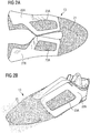
- Figures 2A and 2B show an exemplary non-woven fabric 13.
- the non-woven fabric 13 in the example of figures 2A and 2B has the shape of a shoe upper. In Fig. 2A the part of the non-woven fabric 13 is shown in a planar, two-dimensional configuration, whereas in Fig. 2B it is shown in a three-dimensional configuration.
- the non-woven fabric 13 comprises a first plurality 21 of fibers which have been transferred to a planar substrate (not shown in figures 2A and 2B ) as described above with respect to Fig. 1 .
- Two components 22A and 22B are placed on the first plurality 21 of fibers and the second plurality of fibers has been transferred onto the first plurality 21 of fibers and the components 22A and 22B as described above.
- the two components 22A and 22B are still visible through the second plurality of fibers.
- the components 22A and 22B are reinforcements of the shoe upper which are located on the medial and lateral sides of the shoe upper, respectively.
- the components in the example of figures 2A and 2B are made of TPU.
- a compact TPU material can be used which ensures a good bonding to the TPU fibers and comprises better recycling properties.
- the components 22A and 22B each comprise an opening 23A and 23B, respectively.
- the second plurality of fibers 11 When the second plurality of fibers 11 is transferred to the non-woven fabric 23, fibers 11 will be arranged inside the openings 23A and 23B.
- the fibers of the first plurality 21 of fibers and the second plurality of fibers are bond to each other inside the openings 23A and 23B, but also outside of the components 22A and 22B, respectively. In this way, the components 22A and 22B are firmly held in place by the fibers.
- the component in the context of the present invention may comprise an arbitrary number of openings or may comprise no opening at all.
- the components 22A and 22B may comprise at least one appendix (not shown in the figures) adapted to be surrounded by fibers 11.
- an appendix could have the shape of an anchor or simply be a linear extension.
- the appendix ensures that the component is fixed inside the non-woven and further avoids an unintended slipping of the component.
- the component placed on the first plurality 21 of fibers may comprise such a shape that it is held in place by fibers.
- the component may comprise a textured surface (not shown in the figures). In this way, the fibers coming into contact with the surface of the component will adhere better to the component.
- the components 23A and 23B extend until the edges of the shoe upper.
- the edge of the finished non-woven fabric 13 will show the components 23A and 23B "sandwiched" between the first plurality 21 of fibers and the second plurality of fibers.
- the components 23A and 23B are smaller than the shape of the shoe upper and, thus, are entirely embedded inside the non-woven fabric 13. In this case, the components 23A and 23B may not be visible at all, not even at the edge of the non-woven fabric 13, depending on the non-woven material, color and thickness.
- the at least one surface of the component comprises a meltable layer.
- the meltable layer may face the first plurality 21 of fibers or the second plurality of fibers.
- the hot fibers may melt or soften the meltable layer and may bond to the meltable layer.
- the component may comprise an adhesive which adheres to the fibers 11 without the application of heat. Adhesives or meltable layers may be applied to both sides of a component, such that the component adheres to both the first 21 plurality of fibers and the second plurality of fibers.
- the non-woven fabric 13 shown in figures 2A and 2B has been subject to a heat and pressure treatment in the heel area making the non-woven layer 21 more translucent.
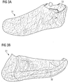
- Figures 3A and 3B show an exemplary non-woven fabric in the shape of a sock-like shoe upper 31 which has been obtained by the method according to the invention as described above.
- the shoe upper 31 comprises a bottom side 32 facing a sole of a shoe (not shown in figures 3A and 3B ).
- the shoe upper 31 has a closed geometry except for the foot opening 33 and is essentially sock-like.
- a sole structure may directly be applied to the bottom side 32 of the shoe upper 31 e.g. by stitching, gluing or welding. It is also possible to apply the shoe sole structure by injection molding. If the sole structure comprises fibers, for example as a cushioning or padding, it is even possible to transfer the fibers from a fiber transfer device 14 as described above while the shoe upper 31 is still on a last. In this way, a part of the sole structure (or even the entire sole structure) may be integrally formed with the shoe upper 31 in a single process.
- first and a second non-woven fabric for a shoe upper are manufactured as described herein. Both non-woven fabrics are different parts of the shoe upper.
- the first non-woven fabric may be a rear portion including a heel counter as a component embedded in the non-woven fabric
- the second non-woven fabric may be a corresponding front portion including a toe counter as a component embedded in the non-woven fabric. Both portions may then be joined by gluing, stitching, welding, etc. to obtain the shoe upper.
- an arbitrary number of such components may be joined to obtain a shoe upper.
- figures 2A, 2B , 3A and 3B show a non-woven fabric 13 obtained according to the method of the invention as a shoe upper or a part thereof
- the non-woven fabric may be generally be used for arbitrary articles and products including for example entire apparels or portions thereof, shoes or portions thereof (including sole structures), sports equipment or portions thereof (including bladders and carcasses), bags or portions thereof, accessories or portions thereof, etc. This list is neither concluding nor limiting.
- Figures 5A and 5B show an embodiment of a variation of the idea of the present invention, namely a shoe 51 comprising a shoe upper 52 and a sole structure 53.
- the shoe upper was obtained by a 2D meltblown process.
- the fibers are blown on a flat surface to form a base layer.
- the base layer is then for example cut to a shoe upper shape and stitched to a lasting board to create a 3D shape.
- the tapes 54 may be created via applying a thicker layer of fibers, for example by spraying/blowing more fibers in certain areas.
- the tapes may be created via heat pressing the base-layer in the areas where tapes needs to be placed. The heating pressing may happen in the areas of the base layer with a higher thickness.
- the tapes may be produced separately and then joined, e.g. heat pressed, to the base layer.
- the tapes may be placed on the base layer and then the intermediate assembly comprising at least a tape and the base layer may be heat pressed so as to be joined together.
- a texturing may be created on the tape and/or on the base layer when heat pressed.
- the different tapes can have a different stretch, for example 5%, 10% or 15% of the stretch of the non-woven base layer.
- the tapes may beneficially be of the same material as the base layer.
- One benefit of this 2D blown fiber/non-woven technology is that a TPU cover layer is not needed, because the non-woven is water resistant.
- an isotropic upper i.e. with equal stretch everywhere
- the local stretch may be modified by the application of tape(s).
- a tape may wrap around the shoe upper or may be interrupted in the form of a patch.
Landscapes
- Engineering & Computer Science (AREA)
- Textile Engineering (AREA)
- Mechanical Engineering (AREA)
- Chemical & Material Sciences (AREA)
- Materials Engineering (AREA)
- Composite Materials (AREA)
- Footwear And Its Accessory, Manufacturing Method And Apparatuses (AREA)
- Nonwoven Fabrics (AREA)
- Laminated Bodies (AREA)
Claims (15)
- Procédé de fabrication d'un textile non tissé (13), comprenant les étapes suivantes :a. mise en place d'un substrat (12), le substrat (12) étant perméable à l'air au moins dans une partie de la surface, la partie perméable à l'air comprenant une pluralité d'orifices (114);b. mise en place d'un dispositif de transfert de fibres (14) apte à transférer des fibres (11) sur le substrat (12),c. transfert sur le substrat (12) d'une première pluralité (21) de fibres (11) ; etd. application d'un différentiel de pression à la partie perméable à l'air du substrat, le différentiel de pression étant appliqué de telle manière que les fibres transférées sur le substrat soient attirées par le différentiel de pression, le niveau du différentiel de pression étant rendu variable sur l'étendue de la surface du substrat (12),
dans lequel :la densité et/ou le diamètre des orifices (114) sont rendus variables sur l'étendue de la surface du substrat (12), et/ou dans lequelles orifices (114) sont agencés en zones, et des sources d'aspiration ou des pompes ayant des puissances différentes sont reliées aux diverses zones. - Procédé selon la revendication précédente, dans lequel le substrat (12) est une forme tridimensionnelle.
- Procédé selon l'une des revendications précédentes, comprenant en outre les étapes suivantes :placement d'un composant (22A, 22B) au moins partiellement sur la première pluralité (21) de fibres (11) transférées sur le substrat (12) ; ettransfert d'une seconde pluralité de fibres (11) sur au moins une partie du composant (22A, 22B) et sur au moins une partie de la première pluralité (21) de fibres (11).
- Procédé selon la revendication précédente, dans lequel le composant a une forme tridimensionnelle.
- Procédé selon l'une des revendications précédentes, dans lequel le dispositif de transfert de fibres (14) est une tête de fusion-soufflage.
- Procédé selon l'une des revendications précédentes, dans lequel le textile non tissé est une partie d'un vêtement, d'une chaussure ou d'un équipement de sport.
- Procédé selon l'une des revendications 2 à 6, dans lequel la forme tridimensionnelle (12) est en forme de ballon et le textile non tissé (13) convient à une utilisation en tant que couche d'un ballon ou en tant que partie de celui-ci.
- Procédé selon l'une des revendications 5 à 7, dans lequel la tête de fusion-soufflage (14) comprend une pluralité de buses (17).
- Procédé selon la revendication précédente, comprenant en outre les étapes suivantes :alimentation d'au moins une première buse (17) par un premier matériau ; etalimentation d'au moins une seconde buse (17) par un second matériau, le premier matériau et le second matériau étant différents.
- Procédé selon l'une des revendications précédentes, comprenant en outre les étapes suivantes :transfert d'un premier matériau pendant un premier laps de temps ; ettransfert d'un second matériau pendant un second laps de temps, le premier matériau et le second matériau étant différents.
- Procédé selon l'une des revendications précédentes, comprenant en outre les étapes suivantes :transfert d'un premier matériau sur une première partie du substrat (12) ; ettransfert d'un second matériau sur une seconde partie du substrat (12), le premier matériau et le second matériau étant différents.
- Textile non tissé (13) fabriqué conformément à un procédé de l'une des revendications précédentes.
- Procédé de fabrication d'une tige de chaussure (13, 31), comprenant l'étape suivante:
fabrication d'un premier textile non tissé (13) conformément au procédé de la revendication 6, le premier textile non tissé étant une partie de la tige de chaussure (13, 31). - Procédé de fabrication d'une tige de chaussure (13, 31) selon la revendication précédente, comprenant en outre les étapes suivantes :fabrication d'un second textile non tissé conformément au procédé de la revendication 6, le second textile non tissé étant une partie de la tige de chaussure (13, 31) ; etassemblage du premier textile non tissé (13) et du second textile non tissé.
- Tige de chaussure (13, 31) fabriquée conformément à un procédé selon l'une des revendications 13 ou 14.
Applications Claiming Priority (1)
| Application Number | Priority Date | Filing Date | Title |
|---|---|---|---|
| DE102016223571.0A DE102016223571B4 (de) | 2016-11-28 | 2016-11-28 | Herstellung von Vliesstoffen einschließlich einer Komponente |
Publications (2)
| Publication Number | Publication Date |
|---|---|
| EP3327191A1 EP3327191A1 (fr) | 2018-05-30 |
| EP3327191B1 true EP3327191B1 (fr) | 2020-10-07 |
Family
ID=60450539
Family Applications (1)
| Application Number | Title | Priority Date | Filing Date |
|---|---|---|---|
| EP17203193.2A Active EP3327191B1 (fr) | 2016-11-28 | 2017-11-23 | Fabrication de tissus non tissés comprenant un composant |
Country Status (5)
| Country | Link |
|---|---|
| US (1) | US10975500B2 (fr) |
| EP (1) | EP3327191B1 (fr) |
| JP (1) | JP6560732B2 (fr) |
| CN (1) | CN108118446B (fr) |
| DE (1) | DE102016223571B4 (fr) |
Families Citing this family (11)
| Publication number | Priority date | Publication date | Assignee | Title |
|---|---|---|---|---|
| US12232564B2 (en) | 2015-11-09 | 2025-02-25 | Under Armour, Inc. | Method of forming an article of footwear |
| EP3589150B1 (fr) * | 2017-02-28 | 2023-05-10 | Under Armour, Inc. | Tige et article chaussant comprenant une tige |
| US10874172B2 (en) * | 2018-04-04 | 2020-12-29 | Adidas Ag | Articles of footwear with uppers comprising a wound component and methods of making the same |
| DE102018220513B4 (de) | 2018-11-28 | 2021-08-26 | Adidas Ag | Verfahren zum Bereitstellen mindestens eines Abschnitts eines Kleidungsstücks oder Schuhwerks und Abschnitt eines Kleidungsstücks oder Schuhwerks |
| DE102019208275B4 (de) * | 2019-06-06 | 2025-03-13 | Adidas Ag | Verfahren zum Bereitstellen eines Vliesstoffes |
| CN111411449B (zh) * | 2020-04-13 | 2021-06-11 | 苏州经结纬面料科技有限公司 | 一种褶皱熔喷面料制备装置及其制备方法 |
| US11602196B2 (en) | 2020-07-13 | 2023-03-14 | Adidas Ag | Articles of footwear comprising a wound component and methods of making the same |
| CH717906A2 (de) * | 2020-09-30 | 2022-03-31 | On Clouds Gmbh C/O On Ag | Verfahren zur Herstellung eines Textilmaterials. |
| US11701823B1 (en) | 2021-05-19 | 2023-07-18 | Under Armour, Inc. | Method of making footwear components |
| WO2025045678A1 (fr) * | 2023-08-31 | 2025-03-06 | On Clouds Gmbh | Produit en feuille textile |
| US12553165B2 (en) | 2023-12-29 | 2026-02-17 | Adidas Ag | Rotational winding apparatus and method |
Citations (1)
| Publication number | Priority date | Publication date | Assignee | Title |
|---|---|---|---|---|
| JP3074549B2 (ja) * | 1991-11-08 | 2000-08-07 | 鈴木総業株式会社 | 不織布製身体装着品並びにその製造方法 |
Family Cites Families (30)
| Publication number | Priority date | Publication date | Assignee | Title |
|---|---|---|---|---|
| GB1363675A (en) | 1971-10-29 | 1974-08-14 | Spraymould Ltd | Method of making shoes |
| US4741941A (en) * | 1985-11-04 | 1988-05-03 | Kimberly-Clark Corporation | Nonwoven web with projections |
| US4666647A (en) * | 1985-12-10 | 1987-05-19 | Kimberly-Clark Corporation | Apparatus and process for forming a laid fibrous web |
| JP2884004B2 (ja) | 1990-06-29 | 1999-04-19 | チッソ株式会社 | 極細繊維成型体の製造方法 |
| WO1992016361A1 (fr) * | 1991-03-20 | 1992-10-01 | Sabee Reinhardt N | Non-tisses presentant des gradients de quantite de fibres |
| CA2105026C (fr) * | 1993-04-29 | 2003-12-16 | Henry Louis Griesbach Iii | Non-tisse forme et sa methode de fabrication |
| JPH07132206A (ja) | 1993-11-09 | 1995-05-23 | Toray Ind Inc | 濾 材 |
| DE19740338A1 (de) * | 1997-09-13 | 1999-03-18 | Truetzschler Gmbh & Co Kg | Vorrichtung zum Herstellen eines Faservlieses, z. B. aus Baumwolle, Chemiefasern, Fasermischungen u. dgl. |
| US6319455B1 (en) * | 1999-08-13 | 2001-11-20 | First Quality Nonwovens, Inc. | Nonwoven fabric with high CD elongation and method of making same |
| JP2002242069A (ja) | 2001-02-15 | 2002-08-28 | Mitsui Chemicals Inc | 混合繊維からなる不織布及びその製造方法並びに該不織布からなる積層体 |
| JP4670166B2 (ja) | 2001-03-21 | 2011-04-13 | トヨタ紡織株式会社 | フィルタの製造方法 |
| DE10132563A1 (de) * | 2001-07-10 | 2003-01-30 | Fleissner Maschf Gmbh Co | Verfahren zur farblosen Musterung einer Warenbahn und Vorrichtung zur Durchführung des Verfahrens |
| DE102005004454B3 (de) * | 2005-02-01 | 2006-10-12 | ERKO Trützschler GmbH | Verfahren zur Herstellung von textilen Formstücken |
| US20060276095A1 (en) | 2005-06-02 | 2006-12-07 | Nike, Inc. | Article of footwear of nonwoven material and method of manufacturing same |
| DE102007035729A1 (de) | 2007-07-30 | 2009-02-05 | Puma Aktiengesellschaft Rudolf Dassler Sport | Verfahren zum Herstellen eines Schuhoberteils |
| KR101597859B1 (ko) | 2008-12-23 | 2016-02-25 | 쓰리엠 이노베이티브 프로퍼티즈 컴파니 | 패턴화된 스펀본드 섬유질 웨브와 그의 제조 및 사용 방법 |
| US8906275B2 (en) | 2012-05-29 | 2014-12-09 | Nike, Inc. | Textured elements incorporating non-woven textile materials and methods for manufacturing the textured elements |
| TWI414657B (zh) | 2010-07-30 | 2013-11-11 | Taiwan Textile Res Inst | 製備立體不織布結構之設備及其方法 |
| CN102345210B (zh) | 2010-07-30 | 2013-07-24 | 财团法人纺织产业综合研究所 | 制备立体不织布结构的设备及其方法 |
| US20130269154A1 (en) * | 2010-10-21 | 2013-10-17 | Norbert Kühl | Method and apparatus for producing a composite nonwoven |
| WO2012168143A1 (fr) * | 2011-06-09 | 2012-12-13 | Oerlikon Textile Gmbh & Co. Kg | Dispositif pour produire un produit fibreux par pose de fibres filées par fusion-soufflage |
| ITTV20120021A1 (it) | 2012-02-10 | 2013-08-11 | Stemma Srl | Metodo per l'applicazione di un inserto in materiale polimerico su un supporto e attrezzatura per l'esecuzione di tale metodo. |
| US9175428B2 (en) | 2012-04-30 | 2015-11-03 | Chen-Cheng Huang | Method of making a double-sided embossed non-woven fabric |
| CN202969127U (zh) * | 2012-12-18 | 2013-06-05 | 潮州市金山塑胶有限公司 | 环保型水性聚氨酯篮球革 |
| US20140272359A1 (en) | 2013-03-15 | 2014-09-18 | The Procter & Gamble Company | Nonwoven substrates |
| JP6326434B2 (ja) | 2013-03-15 | 2018-05-16 | タミケア リミテッド | 非工業的な環境で不織製品を製造するための装置 |
| JP6542787B2 (ja) | 2013-11-26 | 2019-07-10 | スリーエム イノベイティブ プロパティズ カンパニー | 寸法安定性メルトブローン不織布繊維構造とその製造方法及び製造装置 |
| JP2016052721A (ja) | 2014-09-02 | 2016-04-14 | 株式会社フットテクノ | 複合ファブリック3次元構造体 |
| HK1244519B (zh) | 2014-11-10 | 2020-03-20 | 北面服饰公司 | 通过射流挤出工艺形成的鞋类以及其他制品 |
| US20160168774A1 (en) | 2014-12-16 | 2016-06-16 | Nike, Inc. | Nonwoven Material, Method Of Making Same, And Articles Incorporating The Nonwoven Material |
-
2016
- 2016-11-28 DE DE102016223571.0A patent/DE102016223571B4/de active Active
-
2017
- 2017-11-17 US US15/816,141 patent/US10975500B2/en active Active
- 2017-11-23 EP EP17203193.2A patent/EP3327191B1/fr active Active
- 2017-11-27 JP JP2017226406A patent/JP6560732B2/ja active Active
- 2017-11-28 CN CN201711214008.8A patent/CN108118446B/zh active Active
Patent Citations (1)
| Publication number | Priority date | Publication date | Assignee | Title |
|---|---|---|---|---|
| JP3074549B2 (ja) * | 1991-11-08 | 2000-08-07 | 鈴木総業株式会社 | 不織布製身体装着品並びにその製造方法 |
Also Published As
| Publication number | Publication date |
|---|---|
| DE102016223571A1 (de) | 2018-05-30 |
| US20180148861A1 (en) | 2018-05-31 |
| DE102016223571B4 (de) | 2020-08-13 |
| CN108118446A (zh) | 2018-06-05 |
| JP6560732B2 (ja) | 2019-08-14 |
| CN108118446B (zh) | 2021-11-26 |
| US10975500B2 (en) | 2021-04-13 |
| EP3327191A1 (fr) | 2018-05-30 |
| JP2018096021A (ja) | 2018-06-21 |
Similar Documents
| Publication | Publication Date | Title |
|---|---|---|
| US10975500B2 (en) | Method of non-woven fabrics including a component | |
| CN110461587B (zh) | 利用载体网形成的纤维结合工程化材料 | |
| CN107208335B (zh) | 通过射流挤出工艺形成的鞋类以及其他制品 | |
| CN103620100B (zh) | 层状热塑性非编织织物元件 | |
| JP7194108B2 (ja) | 機能性膜を有する層状製品、そのような層状製品を含む履物及び製造方法 | |
| EP2659798B1 (fr) | Procédé de fabrication d'une tige de chaussure | |
| CN106923437A (zh) | 三维形状织物涂层的制造方法 | |
| WO2018218122A1 (fr) | Article chaussant | |
| HK1244519A1 (en) | Footwear and other articles formed by jet extrusion processes | |
| CN121647443A (zh) | 使用区域性垫料形成的纤维结合工程化材料 | |
| WO2018144118A1 (fr) | Matériaux façonnés liés par des fibres, formés sous la forme d'un cuir synthétique | |
| JP2017095849A (ja) | 横編ジャカード方式で製織された接着性生地及びこれを利用した表面モルディング方法 | |
| US12075884B2 (en) | Fiber-bound engineered materials formed using foundation scrims | |
| WO2018137647A1 (fr) | Composé de caoutchouc, semelle en caoutchouc et son procédé de fabrication | |
| KR101647964B1 (ko) | 중공사 결합을 통한 주름방지를 위한 차량용 시트 및 그 제조방법 | |
| CN103031735B (zh) | 仿皮革触感织布的制造方法及由其制得的仿皮革触感织布 | |
| KR20160019724A (ko) | 접착성 원단이 부착된 인솔 | |
| US20260053232A1 (en) | Footwear | |
| TWI484079B (zh) | The method of making the leather felt weaving cloth and the woven fabric made by the method | |
| KR101848372B1 (ko) | 횡편 자카드 방식으로 직조된 접착성 원단 및 이를 이용한 표면 몰딩 방법 | |
| EP4699485A1 (fr) | Chaussure | |
| TW201912395A (zh) | 布面結構及其製造方法 | |
| TWI592531B (zh) | 透氣複合纖維織物 | |
| CN212666879U (zh) | 多层材料 | |
| CN114009899A (zh) | 一种具有高弹性的立体式飞织鞋面及其生产工艺 |
Legal Events
| Date | Code | Title | Description |
|---|---|---|---|
| PUAI | Public reference made under article 153(3) epc to a published international application that has entered the european phase |
Free format text: ORIGINAL CODE: 0009012 |
|
| STAA | Information on the status of an ep patent application or granted ep patent |
Free format text: STATUS: REQUEST FOR EXAMINATION WAS MADE |
|
| 17P | Request for examination filed |
Effective date: 20171123 |
|
| AK | Designated contracting states |
Kind code of ref document: A1 Designated state(s): AL AT BE BG CH CY CZ DE DK EE ES FI FR GB GR HR HU IE IS IT LI LT LU LV MC MK MT NL NO PL PT RO RS SE SI SK SM TR |
|
| AX | Request for extension of the european patent |
Extension state: BA ME |
|
| STAA | Information on the status of an ep patent application or granted ep patent |
Free format text: STATUS: EXAMINATION IS IN PROGRESS |
|
| 17Q | First examination report despatched |
Effective date: 20181218 |
|
| GRAP | Despatch of communication of intention to grant a patent |
Free format text: ORIGINAL CODE: EPIDOSNIGR1 |
|
| STAA | Information on the status of an ep patent application or granted ep patent |
Free format text: STATUS: GRANT OF PATENT IS INTENDED |
|
| RIC1 | Information provided on ipc code assigned before grant |
Ipc: D04H 3/07 20120101ALI20191106BHEP Ipc: B29D 35/00 20100101ALI20191106BHEP Ipc: D04H 1/4374 20120101AFI20191106BHEP Ipc: D04H 1/56 20060101ALI20191106BHEP Ipc: D04H 1/76 20120101ALI20191106BHEP Ipc: A43B 7/00 20060101ALI20191106BHEP Ipc: D04H 3/16 20060101ALI20191106BHEP Ipc: A43B 23/00 20060101ALI20191106BHEP |
|
| INTG | Intention to grant announced |
Effective date: 20191202 |
|
| GRAJ | Information related to disapproval of communication of intention to grant by the applicant or resumption of examination proceedings by the epo deleted |
Free format text: ORIGINAL CODE: EPIDOSDIGR1 |
|
| STAA | Information on the status of an ep patent application or granted ep patent |
Free format text: STATUS: EXAMINATION IS IN PROGRESS |
|
| GRAP | Despatch of communication of intention to grant a patent |
Free format text: ORIGINAL CODE: EPIDOSNIGR1 |
|
| STAA | Information on the status of an ep patent application or granted ep patent |
Free format text: STATUS: GRANT OF PATENT IS INTENDED |
|
| INTC | Intention to grant announced (deleted) | ||
| INTG | Intention to grant announced |
Effective date: 20200423 |
|
| GRAS | Grant fee paid |
Free format text: ORIGINAL CODE: EPIDOSNIGR3 |
|
| GRAA | (expected) grant |
Free format text: ORIGINAL CODE: 0009210 |
|
| STAA | Information on the status of an ep patent application or granted ep patent |
Free format text: STATUS: THE PATENT HAS BEEN GRANTED |
|
| AK | Designated contracting states |
Kind code of ref document: B1 Designated state(s): AL AT BE BG CH CY CZ DE DK EE ES FI FR GB GR HR HU IE IS IT LI LT LU LV MC MK MT NL NO PL PT RO RS SE SI SK SM TR |
|
| REG | Reference to a national code |
Ref country code: GB Ref legal event code: FG4D |
|
| REG | Reference to a national code |
Ref country code: CH Ref legal event code: EP Ref country code: AT Ref legal event code: REF Ref document number: 1321249 Country of ref document: AT Kind code of ref document: T Effective date: 20201015 |
|
| REG | Reference to a national code |
Ref country code: IE Ref legal event code: FG4D |
|
| REG | Reference to a national code |
Ref country code: DE Ref legal event code: R096 Ref document number: 602017024937 Country of ref document: DE |
|
| REG | Reference to a national code |
Ref country code: NL Ref legal event code: MP Effective date: 20201007 |
|
| REG | Reference to a national code |
Ref country code: AT Ref legal event code: MK05 Ref document number: 1321249 Country of ref document: AT Kind code of ref document: T Effective date: 20201007 |
|
| PG25 | Lapsed in a contracting state [announced via postgrant information from national office to epo] |
Ref country code: FI Free format text: LAPSE BECAUSE OF FAILURE TO SUBMIT A TRANSLATION OF THE DESCRIPTION OR TO PAY THE FEE WITHIN THE PRESCRIBED TIME-LIMIT Effective date: 20201007 Ref country code: GR Free format text: LAPSE BECAUSE OF FAILURE TO SUBMIT A TRANSLATION OF THE DESCRIPTION OR TO PAY THE FEE WITHIN THE PRESCRIBED TIME-LIMIT Effective date: 20210108 Ref country code: NO Free format text: LAPSE BECAUSE OF FAILURE TO SUBMIT A TRANSLATION OF THE DESCRIPTION OR TO PAY THE FEE WITHIN THE PRESCRIBED TIME-LIMIT Effective date: 20210107 Ref country code: RS Free format text: LAPSE BECAUSE OF FAILURE TO SUBMIT A TRANSLATION OF THE DESCRIPTION OR TO PAY THE FEE WITHIN THE PRESCRIBED TIME-LIMIT Effective date: 20201007 Ref country code: PT Free format text: LAPSE BECAUSE OF FAILURE TO SUBMIT A TRANSLATION OF THE DESCRIPTION OR TO PAY THE FEE WITHIN THE PRESCRIBED TIME-LIMIT Effective date: 20210208 |
|
| REG | Reference to a national code |
Ref country code: LT Ref legal event code: MG4D |
|
| PG25 | Lapsed in a contracting state [announced via postgrant information from national office to epo] |
Ref country code: IS Free format text: LAPSE BECAUSE OF FAILURE TO SUBMIT A TRANSLATION OF THE DESCRIPTION OR TO PAY THE FEE WITHIN THE PRESCRIBED TIME-LIMIT Effective date: 20210207 Ref country code: PL Free format text: LAPSE BECAUSE OF FAILURE TO SUBMIT A TRANSLATION OF THE DESCRIPTION OR TO PAY THE FEE WITHIN THE PRESCRIBED TIME-LIMIT Effective date: 20201007 Ref country code: LV Free format text: LAPSE BECAUSE OF FAILURE TO SUBMIT A TRANSLATION OF THE DESCRIPTION OR TO PAY THE FEE WITHIN THE PRESCRIBED TIME-LIMIT Effective date: 20201007 Ref country code: BG Free format text: LAPSE BECAUSE OF FAILURE TO SUBMIT A TRANSLATION OF THE DESCRIPTION OR TO PAY THE FEE WITHIN THE PRESCRIBED TIME-LIMIT Effective date: 20210107 Ref country code: AT Free format text: LAPSE BECAUSE OF FAILURE TO SUBMIT A TRANSLATION OF THE DESCRIPTION OR TO PAY THE FEE WITHIN THE PRESCRIBED TIME-LIMIT Effective date: 20201007 Ref country code: ES Free format text: LAPSE BECAUSE OF FAILURE TO SUBMIT A TRANSLATION OF THE DESCRIPTION OR TO PAY THE FEE WITHIN THE PRESCRIBED TIME-LIMIT Effective date: 20201007 Ref country code: SE Free format text: LAPSE BECAUSE OF FAILURE TO SUBMIT A TRANSLATION OF THE DESCRIPTION OR TO PAY THE FEE WITHIN THE PRESCRIBED TIME-LIMIT Effective date: 20201007 |
|
| PG25 | Lapsed in a contracting state [announced via postgrant information from national office to epo] |
Ref country code: NL Free format text: LAPSE BECAUSE OF FAILURE TO SUBMIT A TRANSLATION OF THE DESCRIPTION OR TO PAY THE FEE WITHIN THE PRESCRIBED TIME-LIMIT Effective date: 20201007 Ref country code: HR Free format text: LAPSE BECAUSE OF FAILURE TO SUBMIT A TRANSLATION OF THE DESCRIPTION OR TO PAY THE FEE WITHIN THE PRESCRIBED TIME-LIMIT Effective date: 20201007 |
|
| REG | Reference to a national code |
Ref country code: CH Ref legal event code: PL |
|
| REG | Reference to a national code |
Ref country code: DE Ref legal event code: R097 Ref document number: 602017024937 Country of ref document: DE |
|
| PG25 | Lapsed in a contracting state [announced via postgrant information from national office to epo] |
Ref country code: LU Free format text: LAPSE BECAUSE OF NON-PAYMENT OF DUE FEES Effective date: 20201123 Ref country code: LT Free format text: LAPSE BECAUSE OF FAILURE TO SUBMIT A TRANSLATION OF THE DESCRIPTION OR TO PAY THE FEE WITHIN THE PRESCRIBED TIME-LIMIT Effective date: 20201007 Ref country code: MC Free format text: LAPSE BECAUSE OF FAILURE TO SUBMIT A TRANSLATION OF THE DESCRIPTION OR TO PAY THE FEE WITHIN THE PRESCRIBED TIME-LIMIT Effective date: 20201007 Ref country code: CZ Free format text: LAPSE BECAUSE OF FAILURE TO SUBMIT A TRANSLATION OF THE DESCRIPTION OR TO PAY THE FEE WITHIN THE PRESCRIBED TIME-LIMIT Effective date: 20201007 Ref country code: EE Free format text: LAPSE BECAUSE OF FAILURE TO SUBMIT A TRANSLATION OF THE DESCRIPTION OR TO PAY THE FEE WITHIN THE PRESCRIBED TIME-LIMIT Effective date: 20201007 Ref country code: SM Free format text: LAPSE BECAUSE OF FAILURE TO SUBMIT A TRANSLATION OF THE DESCRIPTION OR TO PAY THE FEE WITHIN THE PRESCRIBED TIME-LIMIT Effective date: 20201007 Ref country code: SK Free format text: LAPSE BECAUSE OF FAILURE TO SUBMIT A TRANSLATION OF THE DESCRIPTION OR TO PAY THE FEE WITHIN THE PRESCRIBED TIME-LIMIT Effective date: 20201007 Ref country code: RO Free format text: LAPSE BECAUSE OF FAILURE TO SUBMIT A TRANSLATION OF THE DESCRIPTION OR TO PAY THE FEE WITHIN THE PRESCRIBED TIME-LIMIT Effective date: 20201007 |
|
| REG | Reference to a national code |
Ref country code: BE Ref legal event code: MM Effective date: 20201130 |
|
| PLBE | No opposition filed within time limit |
Free format text: ORIGINAL CODE: 0009261 |
|
| STAA | Information on the status of an ep patent application or granted ep patent |
Free format text: STATUS: NO OPPOSITION FILED WITHIN TIME LIMIT |
|
| PG25 | Lapsed in a contracting state [announced via postgrant information from national office to epo] |
Ref country code: LI Free format text: LAPSE BECAUSE OF NON-PAYMENT OF DUE FEES Effective date: 20201130 Ref country code: DK Free format text: LAPSE BECAUSE OF FAILURE TO SUBMIT A TRANSLATION OF THE DESCRIPTION OR TO PAY THE FEE WITHIN THE PRESCRIBED TIME-LIMIT Effective date: 20201007 Ref country code: CH Free format text: LAPSE BECAUSE OF NON-PAYMENT OF DUE FEES Effective date: 20201130 |
|
| 26N | No opposition filed |
Effective date: 20210708 |
|
| PG25 | Lapsed in a contracting state [announced via postgrant information from national office to epo] |
Ref country code: IT Free format text: LAPSE BECAUSE OF FAILURE TO SUBMIT A TRANSLATION OF THE DESCRIPTION OR TO PAY THE FEE WITHIN THE PRESCRIBED TIME-LIMIT Effective date: 20201007 Ref country code: AL Free format text: LAPSE BECAUSE OF FAILURE TO SUBMIT A TRANSLATION OF THE DESCRIPTION OR TO PAY THE FEE WITHIN THE PRESCRIBED TIME-LIMIT Effective date: 20201007 Ref country code: IE Free format text: LAPSE BECAUSE OF NON-PAYMENT OF DUE FEES Effective date: 20201123 |
|
| PG25 | Lapsed in a contracting state [announced via postgrant information from national office to epo] |
Ref country code: SI Free format text: LAPSE BECAUSE OF FAILURE TO SUBMIT A TRANSLATION OF THE DESCRIPTION OR TO PAY THE FEE WITHIN THE PRESCRIBED TIME-LIMIT Effective date: 20201007 |
|
| PG25 | Lapsed in a contracting state [announced via postgrant information from national office to epo] |
Ref country code: IS Free format text: LAPSE BECAUSE OF FAILURE TO SUBMIT A TRANSLATION OF THE DESCRIPTION OR TO PAY THE FEE WITHIN THE PRESCRIBED TIME-LIMIT Effective date: 20210207 Ref country code: TR Free format text: LAPSE BECAUSE OF FAILURE TO SUBMIT A TRANSLATION OF THE DESCRIPTION OR TO PAY THE FEE WITHIN THE PRESCRIBED TIME-LIMIT Effective date: 20201007 Ref country code: MT Free format text: LAPSE BECAUSE OF FAILURE TO SUBMIT A TRANSLATION OF THE DESCRIPTION OR TO PAY THE FEE WITHIN THE PRESCRIBED TIME-LIMIT Effective date: 20201007 Ref country code: CY Free format text: LAPSE BECAUSE OF FAILURE TO SUBMIT A TRANSLATION OF THE DESCRIPTION OR TO PAY THE FEE WITHIN THE PRESCRIBED TIME-LIMIT Effective date: 20201007 |
|
| PG25 | Lapsed in a contracting state [announced via postgrant information from national office to epo] |
Ref country code: MK Free format text: LAPSE BECAUSE OF FAILURE TO SUBMIT A TRANSLATION OF THE DESCRIPTION OR TO PAY THE FEE WITHIN THE PRESCRIBED TIME-LIMIT Effective date: 20201007 |
|
| PG25 | Lapsed in a contracting state [announced via postgrant information from national office to epo] |
Ref country code: BE Free format text: LAPSE BECAUSE OF NON-PAYMENT OF DUE FEES Effective date: 20201130 |
|
| PGFP | Annual fee paid to national office [announced via postgrant information from national office to epo] |
Ref country code: DE Payment date: 20251022 Year of fee payment: 9 |
|
| PGFP | Annual fee paid to national office [announced via postgrant information from national office to epo] |
Ref country code: GB Payment date: 20251023 Year of fee payment: 9 |
|
| PGFP | Annual fee paid to national office [announced via postgrant information from national office to epo] |
Ref country code: FR Payment date: 20251022 Year of fee payment: 9 |