EP3327233A1 - Schiebesystem eines fenster- oder türflügels - Google Patents
Schiebesystem eines fenster- oder türflügels Download PDFInfo
- Publication number
- EP3327233A1 EP3327233A1 EP17203170.0A EP17203170A EP3327233A1 EP 3327233 A1 EP3327233 A1 EP 3327233A1 EP 17203170 A EP17203170 A EP 17203170A EP 3327233 A1 EP3327233 A1 EP 3327233A1
- Authority
- EP
- European Patent Office
- Prior art keywords
- cage
- carriage
- longitudinal
- rail
- support
- Prior art date
- Legal status (The legal status is an assumption and is not a legal conclusion. Google has not performed a legal analysis and makes no representation as to the accuracy of the status listed.)
- Granted
Links
Images


Classifications
-
- E—FIXED CONSTRUCTIONS
- E05—LOCKS; KEYS; WINDOW OR DOOR FITTINGS; SAFES
- E05D—HINGES OR SUSPENSION DEVICES FOR DOORS, WINDOWS OR WINGS
- E05D15/00—Suspension arrangements for wings
- E05D15/06—Suspension arrangements for wings for wings sliding horizontally more or less in their own plane
- E05D15/0621—Details, e.g. suspension or supporting guides
- E05D15/066—Details, e.g. suspension or supporting guides for wings supported at the bottom
- E05D15/0678—Details, e.g. suspension or supporting guides for wings supported at the bottom on balls or floating rollers
-
- E—FIXED CONSTRUCTIONS
- E05—LOCKS; KEYS; WINDOW OR DOOR FITTINGS; SAFES
- E05D—HINGES OR SUSPENSION DEVICES FOR DOORS, WINDOWS OR WINGS
- E05D15/00—Suspension arrangements for wings
- E05D15/06—Suspension arrangements for wings for wings sliding horizontally more or less in their own plane
- E05D15/0621—Details, e.g. suspension or supporting guides
- E05D15/066—Details, e.g. suspension or supporting guides for wings supported at the bottom
- E05D15/0682—Details, e.g. suspension or supporting guides for wings supported at the bottom on sliding blocks
-
- E—FIXED CONSTRUCTIONS
- E05—LOCKS; KEYS; WINDOW OR DOOR FITTINGS; SAFES
- E05D—HINGES OR SUSPENSION DEVICES FOR DOORS, WINDOWS OR WINGS
- E05D15/00—Suspension arrangements for wings
- E05D15/06—Suspension arrangements for wings for wings sliding horizontally more or less in their own plane
- E05D15/0621—Details, e.g. suspension or supporting guides
- E05D15/066—Details, e.g. suspension or supporting guides for wings supported at the bottom
- E05D15/0686—Tracks
-
- F—MECHANICAL ENGINEERING; LIGHTING; HEATING; WEAPONS; BLASTING
- F16—ENGINEERING ELEMENTS AND UNITS; GENERAL MEASURES FOR PRODUCING AND MAINTAINING EFFECTIVE FUNCTIONING OF MACHINES OR INSTALLATIONS; THERMAL INSULATION IN GENERAL
- F16C—SHAFTS; FLEXIBLE SHAFTS; ELEMENTS OR CRANKSHAFT MECHANISMS; ROTARY BODIES OTHER THAN GEARING ELEMENTS; BEARINGS
- F16C29/00—Bearings for parts moving only linearly
- F16C29/04—Ball or roller bearings
- F16C29/06—Ball or roller bearings in which the rolling bodies circulate partly without carrying load
- F16C29/0602—Details of the bearing body or carriage or parts thereof, e.g. methods for manufacturing or assembly
- F16C29/0604—Details of the bearing body or carriage or parts thereof, e.g. methods for manufacturing or assembly of the load bearing section
-
- F—MECHANICAL ENGINEERING; LIGHTING; HEATING; WEAPONS; BLASTING
- F16—ENGINEERING ELEMENTS AND UNITS; GENERAL MEASURES FOR PRODUCING AND MAINTAINING EFFECTIVE FUNCTIONING OF MACHINES OR INSTALLATIONS; THERMAL INSULATION IN GENERAL
- F16C—SHAFTS; FLEXIBLE SHAFTS; ELEMENTS OR CRANKSHAFT MECHANISMS; ROTARY BODIES OTHER THAN GEARING ELEMENTS; BEARINGS
- F16C29/00—Bearings for parts moving only linearly
- F16C29/04—Ball or roller bearings
- F16C29/06—Ball or roller bearings in which the rolling bodies circulate partly without carrying load
- F16C29/0602—Details of the bearing body or carriage or parts thereof, e.g. methods for manufacturing or assembly
- F16C29/0609—Details of the bearing body or carriage or parts thereof, e.g. methods for manufacturing or assembly of the ends of the bearing body or carriage where the rolling elements change direction, e.g. end caps
-
- F—MECHANICAL ENGINEERING; LIGHTING; HEATING; WEAPONS; BLASTING
- F16—ENGINEERING ELEMENTS AND UNITS; GENERAL MEASURES FOR PRODUCING AND MAINTAINING EFFECTIVE FUNCTIONING OF MACHINES OR INSTALLATIONS; THERMAL INSULATION IN GENERAL
- F16C—SHAFTS; FLEXIBLE SHAFTS; ELEMENTS OR CRANKSHAFT MECHANISMS; ROTARY BODIES OTHER THAN GEARING ELEMENTS; BEARINGS
- F16C29/00—Bearings for parts moving only linearly
- F16C29/04—Ball or roller bearings
- F16C29/06—Ball or roller bearings in which the rolling bodies circulate partly without carrying load
- F16C29/0633—Ball or roller bearings in which the rolling bodies circulate partly without carrying load with a bearing body defining a U-shaped carriage, i.e. surrounding a guide rail or track on three sides
- F16C29/0635—Ball or roller bearings in which the rolling bodies circulate partly without carrying load with a bearing body defining a U-shaped carriage, i.e. surrounding a guide rail or track on three sides whereby the return paths are provided as bores in a main body of the U-shaped carriage, e.g. the main body of the U-shaped carriage is a single part with end caps provided at each end
- F16C29/0638—Ball or roller bearings in which the rolling bodies circulate partly without carrying load with a bearing body defining a U-shaped carriage, i.e. surrounding a guide rail or track on three sides whereby the return paths are provided as bores in a main body of the U-shaped carriage, e.g. the main body of the U-shaped carriage is a single part with end caps provided at each end with balls
- F16C29/064—Ball or roller bearings in which the rolling bodies circulate partly without carrying load with a bearing body defining a U-shaped carriage, i.e. surrounding a guide rail or track on three sides whereby the return paths are provided as bores in a main body of the U-shaped carriage, e.g. the main body of the U-shaped carriage is a single part with end caps provided at each end with balls with two rows of balls, one on each side of the rail
-
- E—FIXED CONSTRUCTIONS
- E05—LOCKS; KEYS; WINDOW OR DOOR FITTINGS; SAFES
- E05Y—INDEXING SCHEME ASSOCIATED WITH SUBCLASSES E05D AND E05F, RELATING TO CONSTRUCTION ELEMENTS, ELECTRIC CONTROL, POWER SUPPLY, POWER SIGNAL OR TRANSMISSION, USER INTERFACES, MOUNTING OR COUPLING, DETAILS, ACCESSORIES, AUXILIARY OPERATIONS NOT OTHERWISE PROVIDED FOR, APPLICATION THEREOF
- E05Y2201/00—Constructional elements; Accessories therefor
- E05Y2201/60—Suspension or transmission members; Accessories therefor
- E05Y2201/622—Suspension or transmission members elements
- E05Y2201/628—Bearings
-
- E—FIXED CONSTRUCTIONS
- E05—LOCKS; KEYS; WINDOW OR DOOR FITTINGS; SAFES
- E05Y—INDEXING SCHEME ASSOCIATED WITH SUBCLASSES E05D AND E05F, RELATING TO CONSTRUCTION ELEMENTS, ELECTRIC CONTROL, POWER SUPPLY, POWER SIGNAL OR TRANSMISSION, USER INTERFACES, MOUNTING OR COUPLING, DETAILS, ACCESSORIES, AUXILIARY OPERATIONS NOT OTHERWISE PROVIDED FOR, APPLICATION THEREOF
- E05Y2201/00—Constructional elements; Accessories therefor
- E05Y2201/60—Suspension or transmission members; Accessories therefor
- E05Y2201/622—Suspension or transmission members elements
- E05Y2201/638—Cams; Ramps
-
- E—FIXED CONSTRUCTIONS
- E05—LOCKS; KEYS; WINDOW OR DOOR FITTINGS; SAFES
- E05Y—INDEXING SCHEME ASSOCIATED WITH SUBCLASSES E05D AND E05F, RELATING TO CONSTRUCTION ELEMENTS, ELECTRIC CONTROL, POWER SUPPLY, POWER SIGNAL OR TRANSMISSION, USER INTERFACES, MOUNTING OR COUPLING, DETAILS, ACCESSORIES, AUXILIARY OPERATIONS NOT OTHERWISE PROVIDED FOR, APPLICATION THEREOF
- E05Y2600/00—Mounting or coupling arrangements for elements provided for in this subclass
- E05Y2600/10—Adjustable
- E05Y2600/30—Adjustment motion
- E05Y2600/31—Linear motion
- E05Y2600/314—Vertical motion
-
- E—FIXED CONSTRUCTIONS
- E05—LOCKS; KEYS; WINDOW OR DOOR FITTINGS; SAFES
- E05Y—INDEXING SCHEME ASSOCIATED WITH SUBCLASSES E05D AND E05F, RELATING TO CONSTRUCTION ELEMENTS, ELECTRIC CONTROL, POWER SUPPLY, POWER SIGNAL OR TRANSMISSION, USER INTERFACES, MOUNTING OR COUPLING, DETAILS, ACCESSORIES, AUXILIARY OPERATIONS NOT OTHERWISE PROVIDED FOR, APPLICATION THEREOF
- E05Y2900/00—Application of doors, windows, wings or fittings thereof
- E05Y2900/10—Application of doors, windows, wings or fittings thereof for buildings or parts thereof
- E05Y2900/13—Type of wing
- E05Y2900/132—Doors
-
- E—FIXED CONSTRUCTIONS
- E05—LOCKS; KEYS; WINDOW OR DOOR FITTINGS; SAFES
- E05Y—INDEXING SCHEME ASSOCIATED WITH SUBCLASSES E05D AND E05F, RELATING TO CONSTRUCTION ELEMENTS, ELECTRIC CONTROL, POWER SUPPLY, POWER SIGNAL OR TRANSMISSION, USER INTERFACES, MOUNTING OR COUPLING, DETAILS, ACCESSORIES, AUXILIARY OPERATIONS NOT OTHERWISE PROVIDED FOR, APPLICATION THEREOF
- E05Y2900/00—Application of doors, windows, wings or fittings thereof
- E05Y2900/10—Application of doors, windows, wings or fittings thereof for buildings or parts thereof
- E05Y2900/13—Type of wing
- E05Y2900/148—Windows
-
- F—MECHANICAL ENGINEERING; LIGHTING; HEATING; WEAPONS; BLASTING
- F16—ENGINEERING ELEMENTS AND UNITS; GENERAL MEASURES FOR PRODUCING AND MAINTAINING EFFECTIVE FUNCTIONING OF MACHINES OR INSTALLATIONS; THERMAL INSULATION IN GENERAL
- F16C—SHAFTS; FLEXIBLE SHAFTS; ELEMENTS OR CRANKSHAFT MECHANISMS; ROTARY BODIES OTHER THAN GEARING ELEMENTS; BEARINGS
- F16C2226/00—Joining parts; Fastening; Assembling or mounting parts
- F16C2226/50—Positive connections
- F16C2226/60—Positive connections with threaded parts, e.g. bolt and nut connections
-
- F—MECHANICAL ENGINEERING; LIGHTING; HEATING; WEAPONS; BLASTING
- F16—ENGINEERING ELEMENTS AND UNITS; GENERAL MEASURES FOR PRODUCING AND MAINTAINING EFFECTIVE FUNCTIONING OF MACHINES OR INSTALLATIONS; THERMAL INSULATION IN GENERAL
- F16C—SHAFTS; FLEXIBLE SHAFTS; ELEMENTS OR CRANKSHAFT MECHANISMS; ROTARY BODIES OTHER THAN GEARING ELEMENTS; BEARINGS
- F16C2350/00—Machines or articles related to building
Definitions
- the present invention relates to the field of sliding systems of windows leaves or doors.
- the invention applies in particular to windows sliding on a rail on the ground.
- doors or windows with one or more sliding leaves relative to a frame.
- a leaf is able to slide in a generally vertical plane to open or close an opening defined by the frame in a wall for example.
- the leaf or sliding leaf is guided along a guide rail that includes the frame, most often placed on the ground at the bottom rail of the latter.
- the sliding leaf comprises, vis-à-vis the guide rail, one or more carriages which are slidable along the rail, so as to allow the opening and closing of the door or window.
- carriages are fixed to a cross member of the leaf, generally under a lower cross member of the sliding leaf, the weight of the leaf being supported by the carriages resting on the rail then disposed in the cross-beam on the ground.
- a solution to meet the standards for recommendations to fight against energy loss is to increase the insulating surface or favoring the solar gain of the windows leaves for example. Therefore one of the trends is to seek to have the highest possible height of the leaf panel to increase and decrease the part of the technical profile surrounding the panel where the energy losses are observed. For a bay window, so we try to increase the glazed part, called the clear glazing, compared to the so-called technical part.
- the height of the sliding carriages carrying the leaf conditioning the technical metal part it is necessary to seek to minimize the height occupied at the leaf by the sliding carriages.
- the invention aims to meet this need.
- a conventional sliding carriage in the case of a sliding leaf guided by a rail on the ground, comprises a support which is fixed under the lower crossbar of the sliding leaf, and a roller race cage inserted in this support, the rollers being rotatably mounted on their respective axes.
- the truck is not secured to the rail.
- a solution to increase the surface of the leaf panel would involve reducing the height of the carriages, and therefore that of the rollers.
- the Applicant has found, however, that it is difficult to reduce the height of the rollers of such carriages without altering the proper functioning, including the quality of the rolling.
- the patent application KR 2009 0100876A describes a system for opening or closing a sliding window leaf comprising a ball bearing carriage placed under the window jamb and guided in translation on a rail in the frame of the window.
- the trolley T-shaped inverted, comprises a simple cage containing a single ball circulation circuit between a housing in the upper part of the cage and a longitudinal open channel disposed in the center of the cage. The balls present in the channel roll on a central track of said rail.
- the leaf may have a greater glazing clarity, however such trolley is relatively unstable when rolling on a rail. It can easily derail or crash.
- the invention aims to provide an opening assembly whose panel portion occupies as large a surface as possible, and whose sliding system is stable, reliable and able to allow to move a relatively heavy leaf, including a bay window, on a rail in a sleeper cross on the ground.
- the invention provides a sliding system of a leaf capable of sliding in a generally vertical plane to open or close an opening defined by a frame, said system comprising at least one slide carriage fixing under the leaf, and a guide rail of the carriage located at the bottom of the frame.
- Said carriage comprises a rolling cage containing rolling elements in the form of balls or rollers.
- Said carriage cage comprises at its upper part at least one longitudinal housing which contains said rolling elements and in its lower part at least one longitudinal open circulation channel at its base, retaining said rolling elements, said housing and said channel being arranged so that they communicate with each other via hollow sections and receiving curves of the rolling elements, defining recirculation sections capable of guiding the rolling elements between said housing and said channel so that said rolling elements can circulate.
- said sliding system is characterized in that said carriage cage comprises a longitudinal central body which comprises in its upper part two so-called longitudinal housings, and disposed substantially symmetrically with respect to the central longitudinal vertical plane of the cage, and in its lower part two so-called longitudinal traffic channels, open at their base, and disposed substantially symmetrically with respect to said longitudinal central vertical plane of the cage, and in that said cage comprises two end recirculating members respectively abutting with said central body, said parts each comprising two recirculation sections disposed opposite each other; on either side of said central longitudinal vertical plane of the cage, the recirculation sections of the same longitudinal side of the recirculation parts respectively connecting an end of said housing and a said channel of said same side.
- said cage is inserted into a support to be fixed to the leaf, said support comprising two hollow support pieces arranged in respective engagement with said recirculating parts of the cage so that the cage is retained between these two support pieces, and said support pieces and said recirculation pieces have respective contacting surfaces which are sloping for one another and the other convex so that said stepped and curved surfaces cooperate with each other to allow a rocking movement of the sliding carriage resting on the rail.
- the two housings and the two channels are thus arranged so that a housing and a channel on the same longitudinal side of the cage communicate with each other via two recirculation sections, a section connecting the respective ends of a housing and channel closer to each other.
- Said housing, said channel and the recirculation sections connecting them define a circulation circuit rolling elements of the carriage for a given side of the carriage.
- the carriage according to the invention therefore comprises two circulation circuits of the rolling elements arranged symmetrically with respect to the central longitudinal vertical plane of the cage.
- the housings are arranged parallel to each other, as are the channels are parallel to each other.
- the central body of the cage is particularly advantageously of parallelepipedal shape.
- Said carriage of the sliding system according to the invention is thus very stable, and is able to roll on a rail disposed in the lower part of a frame particularly placed on the ground. It is able to slide a leaf along a guide rail with a rocking movement that tracks the relief of the rail.
- the rolling elements, balls or rollers are arranged contiguous and so that they can be made mobile in rotation on themselves and in translation by guiding in the circulation circuit under the action of translational movement of the carriage, in support along the guide rail under the weight of the leaf on which is exerted thrust.
- the carriage of the sliding system according to the invention is able to roll bearing on the guide rail during the movement of the leaf, said carriage resting on the rail without enclosing said rail.
- the carriage is not secured to the rail, so it can be installed or removed from the leaf, the rail being in place.
- said respective surfaces of the recirculating pieces and support pieces coming into contact are formed for one by a sloping inner ramp present on each of the longitudinal (internal) side walls of each of said parts. support and for others by a curved surface on the upper face of each of said recirculation pieces.
- the curved surfaces can be provided on the inside of the support parts and the sloping surfaces provided at the level of the cage, however this embodiment is a little less effective than the preferred mode described above to generate the truck rocking movement to follow the relief of the rail.
- each recirculation piece comprises a proximal portion whose surface is curved, and each said support piece has on its longitudinal side walls a sloping inner ramp coming into contact with the convex face of said upper face of the recirculation room.
- said recirculation pieces each have an upper face comprising a generally horizontal proximal portion whose surface is curved, extended by an inclined distal portion.
- the inclined portion promotes in particular the handling of the truck during installation under the leaf.
- the qualifiers "distal” and “proximal” are defined relative to the central body of the cage.
- the cage comprising two circuits for circulating the rolling elements
- this part comprises two hollow and curved recirculation sections which are arranged facing each other on either side of said part, in particular on the one hand and on the other side.
- other of the vertical longitudinal plane of symmetry of the housing and circulation channels ie the central longitudinal vertical plane of the cage, so that a section opens on the one hand at the end of a housing of the upper part of the central body and on the other hand at the end of a circulation channel in the lower part of the central body, channel open at its base, and which are present on the same side of said plane of symmetry.
- said housings in the upper part of the central body of the cage are eccentric with respect to said corresponding channels in the lower part, the recirculation sections connecting a said housing and a said channel on the same longitudinal side of the cage being in a plane substantially inclined relative to the longitudinal vertical plane of the cage.
- the guide rail comprises two longitudinal raceways, arranged so that a path comes in correspondence with the base of the carriage circulation channel on the same side as it. More particularly, said two raceways are arranged symmetrically with respect to the longitudinal vertical plane of symmetry of the longitudinal traffic channels of the carriage, so that the rolling elements retained in a circulation channel appearing in the open base of said channel can rest in support. on said raceway in correspondence with the channel, when the carriage is mounted under the leaf.
- said paths are parallel to one another. Said raceways are present on the upper face of the rail.
- said two longitudinal raceways of the rail arranged so that the rolling elements retained in a circulation channel and appearing in its open base can bear on the race in correspondence with said channel ( when the carriage is under the leaf), are such that each raceway of the rail is in the form of a groove (hollowed in the rail) of a shape substantially adapted to that of the rolling elements.
- said rail of the sliding system has a central longitudinal edge useful for guiding the carriage, said edge being positioned between the longitudinal channels of the carriage when the carriage is resting on the rail, or when the carriage is mounted under the leaf.
- said paths are separated by said central edge useful for guiding the carriage.
- said support pieces are retained together by a screw-nut type connection.
- the carriage is further adjustable in height, and by a screw-nut type connection solidarisant the two support parts together.
- said connecting screw allows the height adjustment of the cage in its support, under the action of screwing / unscrewing of said screw, by sliding of the upper face of a recirculation piece in its workpiece.
- support which has on each of its longitudinal walls a sloping inner ramp coming into contact with a convex surface of said upper face of the cage.
- said connecting screw also passes through a groove present along the upper face of the cage.
- said sliding system comprises a fastening stud secured to the carriage support by interlocking at the end of one of said parts of the carriage support, and which makes it possible to fix the carriage to the gate of the leaf.
- said carriage may be equipped with scrapers, preferably of beveled shape, arranged at its ends, at the level of the recirculation pieces, in order to remove various soils, and in particular pebbles or gravel present on the rail sliding.
- the invention also relates to an opening assembly comprising a leaf capable of sliding in a generally vertical plane to open or close an opening delimited by a frame and a sliding system to at least one carriage secured to the lower rail of the leaf, guided in support on a rail secured to the frame, characterized in that said sliding system is as previously described.
- said rail is arranged at the bottom of the frame. More particularly according to the invention, said rail is secured to the bottom rail of the frame placed on the ground. The leaf thus slides in its own vertical plane, on a rail in a crossbar on the ground.
- the leaf is glazed.
- it is fully glazed, forming a bay window.
- the invention also relates to a sliding leaf, able to be guided along a guide rail, in particular a rail arranged in a horizontal low sleeper cross.
- Said leaf comprises, secured to one of its horizontal sleepers, at least a rolling carriage with recirculation of rolling elements in the form of balls or rollers, which allows its sliding along said rail for its opening and closing in a sliding system as described above according to the invention.
- the invention relates to a leaf with glazed panel, in particular entirely glazed.
- the invention will be described in the context of a particular non-limiting example of a sliding system comprising a trolley recirculating rolling elements in the form of balls, and fixing in the lower part of the leaf that it supports.
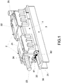
- the figure 1 represents a sliding system according to the invention, comprising a sliding carriage and a rail, said carriage comprising a cage 1, containing rolling balls, inserted in its support 2, and shown positioned on a guide rail 3, said carriage being intended to be fixed to the cross section P of a sliding leaf V, for example a window, as schematically illustrated in FIG. figure 7 .
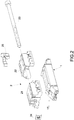
- a feature of the invention is the cage of the carriage shown exploded in figure 3 and in longitudinal section in figure 4 .
- This cage 1 comprises two longitudinal cylindrical housings 100 and 101, hollowed in the upper part of the central body 10 of the cage.
- the central body of the cage has a generally parallelepipedal shape.
- These housings are arranged parallel to each other in the body of the cage, symmetrically with respect to the longitudinal vertical plane of the cage, and they contain balls B0.
- Each end of the housing is extended by a recirculation section formed by a cavity, having a cylindrical shape describing a curve in a substantially vertical longitudinal plane.
- a housing 100 is extended by two extreme cavities 1001, 1002 present respectively at each cage end 11, 12, which guide the balls in circulation in a generally substantially vertical longitudinal plane.
- These cavities are connected at their other end to channels present in part bottom of the central body of the cage.
- These longitudinal channels of circulation of the balls 102, 103 are open at their base ( figure 5 or 4 ).
- the circulation channel is sufficiently open at its base so that the balls B1 can be in contact with the rail, while being sufficiently closed to keep the balls captive.
- the circulation channel has indeed a generally cylindrical shape with a radius of curvature adapted to the size of the balls which allows to retain the balls while guiding their circulation by contact on the raceway of the guide rail of the trolley. support on the rail.
- the balls in a housing 100 in the upper part of the central body of the cage are circulated pushed by the balls which move contiguously in the circulation channel during displacement by longitudinal translation of the carriage carrying the leaf that is to slide .
- Said housing 100 guides them to its exit towards a recirculation cavity of the cage 1002 which guides them to the longitudinal circulation channel 102 in the lower part of the central body 10 of the cage until reaching at the end of the cage another recirculation recirculation cavity 1001 which guide them again in said longitudinal housing 100.
- the balls thus circulate in a loop between their housing and the open circulation channel on the raceway of the carriage guide rail when the carriage moves to make slide the leaf in translation by guiding against the rail.
- the carriage comprising two symmetrical arrangements of rows of contiguous balls, and it rolls on two parallel longitudinal raceways between them, present symmetrically on either side of the guide rail. Said paths are advantageously separated by a central longitudinal edge contributing to the guiding of the carriage.
- the housing in the upper part of the central body of the cage are slightly eccentric compared to the channels at the bottom.
- the recirculation sections connecting a housing and a channel of the same side are then slightly inclined relative to the longitudinal vertical plane.
- the angle of inclination can be in particular chosen between 30 and 45 degrees.
- the sliding carriage, sliding leaf carrier is such that the cage comprises the rolling elements (balls or rollers) arranged tightly tight so as to form in the open base of the channels a continuous rolling surface.
- the number of rolling elements contained in the carriage is a function of the weight of the leaf that said carriage must support.
- the length of the carriage is accordingly a function of the number of rolling elements necessary for said elements of a given circulation circuit remain contiguous.
- the material of the rolling elements is chosen according to the technical criteria of use and physical characteristics of the leaves to be equipped. They may be for example metal, in particular steel, or a material based on polymer (s), composite or ceramic.
- the diameter of the rolling elements is chosen to suit the minimum dimension of the carriage corresponding to the minimum sliding cross member to be equipped. For example, a diameter of 4 mm could be suitable for a leaf of usual window.
- the cage ends are in this particular example in the form of separate parts 11, 12, said recirculation parts, which comprise the curved cavities forming the recirculation sections abutting respectively on either side of the central body of the cage.
- said recirculation pieces 11, 12 are secured by screwing to the central body of the cage 10.
- the fixing screws 15, 16 of the recirculation member 12 which will pass through said part passing through the corresponding respective slot 150, 160 of said part to be screwed respectively in the corresponding lights 19, 18 of the central body 10 .
- each of the ends 11 and 12 of the cage of the carriage has a particular curved surface shape to give, in cooperation with stepped internal surfaces of the support forms, a certain amplitude of relative movements between the cage and its support. It is indeed created as a possible rocking movement between the rectilinear ramps 210, 220 of the support members 21, 22 and the curved faces 111, 121 of the cage.
- the carriage can thus roll with a certain so-called rocking movement which allows the carriage to follow the tracks of the guide rail which may not be perfectly flat both in the horizontal and vertical plane.
- This shape comprises a tapered portion at the distal upper portion 110, 120 and a domed portion at the proximal upper portion 111, 121.
- the upper face of each end of the cage of the carriage comprises a proximal portion in a generally horizontal plane but whose surface is curved, extended by an inclined distal portion.
- the support 2 may, according to a preferred example of the invention, comprise two separate recessed parts 21, 22, which respectively fit at the ends of the cage 11, 12, the two recirculating elements of the rolling elements, engaged with each other. their upper faces 110, 111; 120,121, a screw-type connection solidarisant the support parts together so that said support parts hold the cage between them.
- sloping ramps 210, 220 which bear on the convex proximal face of the corresponding cage end.
- the shape of these ends is useful for adjusting the height of the carriage by a wedge effect that will raise or lower the cage in the support under the action of a screw-nut type connection between the cage and the support.
- a concave central groove 17 is hollowed longitudinally on the upper external face of the cage, on the recirculation pieces and the central body, to receive the connecting screw 23.
- the screw head 23 is introduced into a hole made in the transverse wall (Extreme) of one of the two parts of the support 22 which covers an end wall of the cage, where it is retained by the head.
- the screw goes into the groove of the cage until its threaded end opens through a light in the transverse wall (end) of the other support part 21 which covers the other end wall of the cage, and to fit and screw into a nut 24 embedded in this support part end.
- the cage is maintained at its ends, taken in pincers, between the two parts of the support.
- the parts of the support 21, 22 are slid on the cage by sliding of the internal ramps of the support pieces resting on the curved faces 111, 121 of the end pieces of the cage 11, 12 , which makes it possible to act on the height of the cage in the support, and consequently to adjust the height of the carriage by wedge effect.
- the angle of inclination of the distal upper face of the ends of the cage is preferably about 60 degrees with respect to the treads of the carriage on the rail (i.e. the horizontal).
- the connecting screw 23 between the cage and its support may have a relatively long adjustment stroke, which is advantageous for adjusting the height of a carriage carrying a relatively heavy leaf.
- the adjustment of the height of the carriage can be easily finalized once the leaf is placed in its receiver frame.
- a fastening stud 25 is secured to the carriage support, for example by interlocking at the end of one of the parts of the carriage support 22, which block makes it possible to fix the carriage to the cross member of the leaf, according to this example in FIG. the lower crossbar of the leaf V, in particular under the crossbar.
- this stud may also be useful for guiding the tightening key of the cage-support connection screw and also for adjusting the height of the carriage, for example by virtue of a recess into which the key will pass.
- the carriage according to the invention can operate on a guide rail known per se and commonly used for roller carriages, the raceways for the rolling elements (balls or rollers) located on the upper face of the rail, on either side of the central longitudinal projecting guiding line of substantially triangular section and which usually serves as a rolling track of the rollers.
- the guide rail of the carriage is advantageously a rail adapted to the carriage with ball bearings (or rollers), described above.
- each raceway of the guide rail is then in the form of a longitudinal groove 31, 32.
- the groove has a shape adapted to the rolling elements, for example for balls it has a Concave shape whose rounding is adapted to ensure good contact between the balls and the rail and to help better guide and rolling balls. Such an example is illustrated in figure 1 or figure 5 .
- FIG 5 in a transverse central sectional view of the carriage of the carriage disposed on the guide rail 3, illustrates the balls B12 and B13 circulating on their respective longitudinal raceway 32, 31 of the rail 3, while being also guided, respectively at their carriage side, in the longitudinal channels 102, 103 open at the bottom of the central body of the cage.
- the central ridge 30 which protrudes by separating these raceways on the upper face of the rail may be useful for improving the guidance of the carriage on the rail.
- the carriage in order to avoid soiling during the use of the slide carriage on a rail on the ground in particular, the carriage can advantageously be equipped with scrapers R1, R2 preferably of beveled shape for greater efficiency, arranged at its ends, at the level of the recirculation pieces 11, 12.
- Brushes can also be installed on the carriage and / or on the leaf, and preferably disposed more ends than the scrapers when they are on the carriage.
- the invention has been illustrated in the context of the particular example of a recirculating ball carriage, but may be easily adapted to the case of rolls which are in the form of small cylinders.
- the rolling elements are in the form of a plurality of rollers
- said elements are arranged one after the other, transversely, along their axis of revolution, in the receiving parts.
- the carriage cage that are the housing, channels and recirculation sections forming the circulation circuit of said elements.
- Said receiving parts have a generally parallelepipedal shape adapted to contain or retain these elements.
- the grooves forming the raceways of the guide rail have a generally parallelepiped shape adapted to the rollers.
- the sliding system according to the invention makes it possible, surprisingly, to obtain a good rolling of the carriage on the rail in order to slide a leaf which it supports, even of high weight, even though the rolling elements, balls or rollers, are smaller in diameter than the pebbles usually used in this field. Because the height of the carriage is less than that of a roller carriage, the cage being very compact, advantageously allows that the so-called clear part of the window glazing may be larger, this favoring the solar gains, while having a stable ride.
- the carriage being balanced by its operation with two circulation circuits gives a sliding carriage, and therefore the leaf, very stable.
- the carriage of the sliding system makes it possible to sliding a leaf along a guide rail with a rocking movement that tracks the relief of the rail, which prevents the truck from blocking or derailing on its running path. And although the rail and the carriage are not directly attached to each other, the carriage being secured only to the leaf, and the rail to the frame.
- the sliding system according to the invention is well suited to provide a sliding system for a sliding picture window on a guide rail arranged at the bottom of a frame, particularly on the ground.
- this carriage also has the additional advantage of being adjustable in height, even secured to a leaf already installed.
Landscapes
- Engineering & Computer Science (AREA)
- General Engineering & Computer Science (AREA)
- Mechanical Engineering (AREA)
- Bearings For Parts Moving Linearly (AREA)
Priority Applications (1)
| Application Number | Priority Date | Filing Date | Title |
|---|---|---|---|
| PL17203170T PL3327233T3 (pl) | 2016-11-23 | 2017-11-22 | System przesuwu skrzydła drzwiowego |
Applications Claiming Priority (1)
| Application Number | Priority Date | Filing Date | Title |
|---|---|---|---|
| FR1661385A FR3059030B1 (fr) | 2016-11-23 | 2016-11-23 | Chariot porteur de vantail coulissant et systeme de coulissement le comprenant |
Publications (2)
| Publication Number | Publication Date |
|---|---|
| EP3327233A1 true EP3327233A1 (de) | 2018-05-30 |
| EP3327233B1 EP3327233B1 (de) | 2019-11-20 |
Family
ID=58213248
Family Applications (1)
| Application Number | Title | Priority Date | Filing Date |
|---|---|---|---|
| EP17203170.0A Active EP3327233B1 (de) | 2016-11-23 | 2017-11-22 | Schiebesystem eines fenster- oder türflügels |
Country Status (6)
| Country | Link |
|---|---|
| EP (1) | EP3327233B1 (de) |
| ES (1) | ES2767091T3 (de) |
| FR (1) | FR3059030B1 (de) |
| MA (1) | MA44220B1 (de) |
| PL (1) | PL3327233T3 (de) |
| PT (1) | PT3327233T (de) |
Cited By (3)
| Publication number | Priority date | Publication date | Assignee | Title |
|---|---|---|---|---|
| IT201900006348A1 (it) * | 2019-04-24 | 2020-10-24 | Giesse Spa | Serramento scorrevole. |
| IT201900006352A1 (it) * | 2019-04-24 | 2020-10-24 | Giesse Spa | Serramento scorrevole. |
| DE102020210443A1 (de) | 2020-08-17 | 2022-02-17 | Roto Frank Fenster- und Türtechnologie GmbH | Laufwagenanordnung mit wälzlagergeführter Kraftabtragung in Verschieberichtung sowie Fenster oder Tür mit einer solchen Laufwagenanordnung |
Citations (4)
| Publication number | Priority date | Publication date | Assignee | Title |
|---|---|---|---|---|
| FR730922A (fr) * | 1932-02-02 | 1932-08-26 | Ver Baubeschlag Gretsch Co | Roulement à billes pour portes coulissantes |
| JPH076350U (ja) * | 1993-06-30 | 1995-01-31 | 株式会社マルハチ | 天窓装置 |
| JP2003184410A (ja) * | 2001-12-17 | 2003-07-03 | Icm:Kk | 可動式間仕切りシステム |
| KR20090100876A (ko) * | 2008-03-21 | 2009-09-24 | (주)엘지하우시스 | 창문 개/폐용 베어링 타입의 회전형 롤러 |
-
2016
- 2016-11-23 FR FR1661385A patent/FR3059030B1/fr active Active
-
2017
- 2017-11-22 MA MA44220A patent/MA44220B1/fr unknown
- 2017-11-22 ES ES17203170T patent/ES2767091T3/es active Active
- 2017-11-22 EP EP17203170.0A patent/EP3327233B1/de active Active
- 2017-11-22 PL PL17203170T patent/PL3327233T3/pl unknown
- 2017-11-22 PT PT172031700T patent/PT3327233T/pt unknown
Patent Citations (4)
| Publication number | Priority date | Publication date | Assignee | Title |
|---|---|---|---|---|
| FR730922A (fr) * | 1932-02-02 | 1932-08-26 | Ver Baubeschlag Gretsch Co | Roulement à billes pour portes coulissantes |
| JPH076350U (ja) * | 1993-06-30 | 1995-01-31 | 株式会社マルハチ | 天窓装置 |
| JP2003184410A (ja) * | 2001-12-17 | 2003-07-03 | Icm:Kk | 可動式間仕切りシステム |
| KR20090100876A (ko) * | 2008-03-21 | 2009-09-24 | (주)엘지하우시스 | 창문 개/폐용 베어링 타입의 회전형 롤러 |
Cited By (7)
| Publication number | Priority date | Publication date | Assignee | Title |
|---|---|---|---|---|
| IT201900006348A1 (it) * | 2019-04-24 | 2020-10-24 | Giesse Spa | Serramento scorrevole. |
| IT201900006352A1 (it) * | 2019-04-24 | 2020-10-24 | Giesse Spa | Serramento scorrevole. |
| WO2020217125A1 (en) * | 2019-04-24 | 2020-10-29 | Giesse S.P.A. | Sliding door or window |
| WO2020217148A1 (en) * | 2019-04-24 | 2020-10-29 | Giesse S.P.A. | Sliding door or window. |
| DE102020210443A1 (de) | 2020-08-17 | 2022-02-17 | Roto Frank Fenster- und Türtechnologie GmbH | Laufwagenanordnung mit wälzlagergeführter Kraftabtragung in Verschieberichtung sowie Fenster oder Tür mit einer solchen Laufwagenanordnung |
| WO2022037903A1 (de) | 2020-08-17 | 2022-02-24 | Roto Frank Fenster- und Türtechnologie GmbH | Laufwagenanordnung mit wälzlagergeführter kraftabtragung in verschieberichtung sowie fenster oder tür mit einer solchen laufwagenanordnung |
| US12104418B1 (en) | 2020-08-17 | 2024-10-01 | Roto Frank Fenster- und Türtechnologie GmbH | Window or door having a carriage arrangement with roller bearing-guided force dissipation in the displacement direction |
Also Published As
| Publication number | Publication date |
|---|---|
| PT3327233T (pt) | 2020-01-30 |
| MA44220A (fr) | 2018-05-30 |
| FR3059030B1 (fr) | 2021-06-04 |
| PL3327233T3 (pl) | 2020-05-18 |
| ES2767091T3 (es) | 2020-06-16 |
| EP3327233B1 (de) | 2019-11-20 |
| FR3059030A1 (fr) | 2018-05-25 |
| MA44220B1 (fr) | 2020-04-30 |
Similar Documents
| Publication | Publication Date | Title |
|---|---|---|
| EP3327233B1 (de) | Schiebesystem eines fenster- oder türflügels | |
| FR2573143A1 (fr) | Glissiere a rouleaux a mouvement lineaire | |
| FR2516612A1 (fr) | Glissiere de roulement | |
| EP2339104B1 (de) | Laufwagen für eine Schiebetür und aufweisend drei Laufrollen. | |
| FR2546995A1 (fr) | Dispositif de reglage de jeu dans une glissiere lineaire de support | |
| FR2958141A1 (fr) | Chariot d'entrainement pour rideau coulissant | |
| EP1656974B1 (de) | Einrichtung zur Montage von Sicherheitsbindungsteilen auf einen Ski | |
| FR2936005A1 (fr) | Systeme de porte pour salle propre. | |
| FR2613005A1 (fr) | Systemes coulissants en particulier du type a palier lisse lineaire | |
| FR2925098A1 (fr) | Dispositif formant chariot mobile | |
| FR3088949A1 (fr) | Chariot pour ouvrant coulissant, ouvrant coulissant et ensemble ouvrant comprenant un tel chariot | |
| FR2601408A1 (fr) | Dispositif de support et/ou de guidage de la partie inferieure d'une paroi coulissante verticale. | |
| FR2514088A1 (fr) | Patin de roulement | |
| WO2020188166A1 (fr) | Dispositif de guidage pour vitre coulissante de vehicule | |
| FR2464789A1 (fr) | Systeme de glissieres pour machine-outil et procede de montage de deux chariots de machine l'un sur l'autre | |
| EP2288775B1 (de) | Schliesseinrichtung mit schiebeflügeln | |
| EP1116843B1 (de) | Laufschuh für Schiebeflügel, insbesondere für Flügel mit unterbrochener Wärmebrücke | |
| EP1054129A1 (de) | Motorisierte Öffnungs- und Schliessvorrichtung für einen Torflügel oder dergleichen | |
| FR2544814A1 (fr) | Glissiere a billes et table coulissante | |
| EP0876239A1 (de) | Hochgenauigkeitslinearführung | |
| FR2502677A1 (fr) | Dispositif de guidage en translation et baie coulissante pourvue d'un tel dispositif | |
| EP0816615B1 (de) | Aufhängevorrichtung mit profilierten Rollen | |
| FR2696780A1 (fr) | Dispositif d'indexation pour vantail de porte monté coulissant par des roulettes à gorge sur un rail de guidage. | |
| FR2911162A1 (fr) | Chariot de coulissement pour vantail coulissant dans un dormant. | |
| FR3025549A1 (fr) | Chariot de coulissement reglable en hauteur |
Legal Events
| Date | Code | Title | Description |
|---|---|---|---|
| PUAI | Public reference made under article 153(3) epc to a published international application that has entered the european phase |
Free format text: ORIGINAL CODE: 0009012 |
|
| STAA | Information on the status of an ep patent application or granted ep patent |
Free format text: STATUS: THE APPLICATION HAS BEEN PUBLISHED |
|
| AK | Designated contracting states |
Kind code of ref document: A1 Designated state(s): AL AT BE BG CH CY CZ DE DK EE ES FI FR GB GR HR HU IE IS IT LI LT LU LV MC MK MT NL NO PL PT RO RS SE SI SK SM TR |
|
| AX | Request for extension of the european patent |
Extension state: BA ME |
|
| STAA | Information on the status of an ep patent application or granted ep patent |
Free format text: STATUS: REQUEST FOR EXAMINATION WAS MADE |
|
| GRAP | Despatch of communication of intention to grant a patent |
Free format text: ORIGINAL CODE: EPIDOSNIGR1 |
|
| STAA | Information on the status of an ep patent application or granted ep patent |
Free format text: STATUS: GRANT OF PATENT IS INTENDED |
|
| 17P | Request for examination filed |
Effective date: 20181120 |
|
| RAV | Requested validation state of the european patent: fee paid |
Extension state: MA Effective date: 20181120 |
|
| RBV | Designated contracting states (corrected) |
Designated state(s): AL AT BE BG CH CY CZ DE DK EE ES FI FR GB GR HR HU IE IS IT LI LT LU LV MC MK MT NL NO PL PT RO RS SE SI SK SM TR |
|
| RIC1 | Information provided on ipc code assigned before grant |
Ipc: E05D 15/06 20060101AFI20181130BHEP Ipc: F16C 29/06 20060101ALI20181130BHEP Ipc: F16C 29/04 20060101ALN20181130BHEP |
|
| INTG | Intention to grant announced |
Effective date: 20181221 |
|
| RIC1 | Information provided on ipc code assigned before grant |
Ipc: E05D 15/06 20060101AFI20181207BHEP Ipc: F16C 29/04 20060101ALN20181207BHEP Ipc: F16C 29/06 20060101ALI20181207BHEP |
|
| GRAJ | Information related to disapproval of communication of intention to grant by the applicant or resumption of examination proceedings by the epo deleted |
Free format text: ORIGINAL CODE: EPIDOSDIGR1 |
|
| STAA | Information on the status of an ep patent application or granted ep patent |
Free format text: STATUS: REQUEST FOR EXAMINATION WAS MADE |
|
| GRAP | Despatch of communication of intention to grant a patent |
Free format text: ORIGINAL CODE: EPIDOSNIGR1 |
|
| INTC | Intention to grant announced (deleted) | ||
| STAA | Information on the status of an ep patent application or granted ep patent |
Free format text: STATUS: GRANT OF PATENT IS INTENDED |
|
| INTG | Intention to grant announced |
Effective date: 20190606 |
|
| RIC1 | Information provided on ipc code assigned before grant |
Ipc: F16C 29/04 20060101ALN20190527BHEP Ipc: E05D 15/06 20060101AFI20190527BHEP Ipc: F16C 29/06 20060101ALI20190527BHEP |
|
| GRAS | Grant fee paid |
Free format text: ORIGINAL CODE: EPIDOSNIGR3 |
|
| GRAA | (expected) grant |
Free format text: ORIGINAL CODE: 0009210 |
|
| STAA | Information on the status of an ep patent application or granted ep patent |
Free format text: STATUS: THE PATENT HAS BEEN GRANTED |
|
| AK | Designated contracting states |
Kind code of ref document: B1 Designated state(s): AL AT BE BG CH CY CZ DE DK EE ES FI FR GB GR HR HU IE IS IT LI LT LU LV MC MK MT NL NO PL PT RO RS SE SI SK SM TR |
|
| REG | Reference to a national code |
Ref country code: GB Ref legal event code: FG4D Free format text: NOT ENGLISH |
|
| REG | Reference to a national code |
Ref country code: CH Ref legal event code: EP |
|
| REG | Reference to a national code |
Ref country code: IE Ref legal event code: FG4D Free format text: LANGUAGE OF EP DOCUMENT: FRENCH |
|
| REG | Reference to a national code |
Ref country code: DE Ref legal event code: R096 Ref document number: 602017008874 Country of ref document: DE |
|
| REG | Reference to a national code |
Ref country code: AT Ref legal event code: REF Ref document number: 1204373 Country of ref document: AT Kind code of ref document: T Effective date: 20191215 |
|
| REG | Reference to a national code |
Ref country code: PT Ref legal event code: SC4A Ref document number: 3327233 Country of ref document: PT Date of ref document: 20200130 Kind code of ref document: T Free format text: AVAILABILITY OF NATIONAL TRANSLATION Effective date: 20200122 |
|
| REG | Reference to a national code |
Ref country code: CH Ref legal event code: NV Representative=s name: VALIPAT S.A. C/O BOVARD SA NEUCHATEL, CH |
|
| REG | Reference to a national code |
Ref country code: NL Ref legal event code: MP Effective date: 20191120 |
|
| REG | Reference to a national code |
Ref country code: LT Ref legal event code: MG4D |
|
| REG | Reference to a national code |
Ref country code: MA Ref legal event code: VAGR Ref document number: 44220 Country of ref document: MA Kind code of ref document: B1 |
|
| PG25 | Lapsed in a contracting state [announced via postgrant information from national office to epo] |
Ref country code: FI Free format text: LAPSE BECAUSE OF FAILURE TO SUBMIT A TRANSLATION OF THE DESCRIPTION OR TO PAY THE FEE WITHIN THE PRESCRIBED TIME-LIMIT Effective date: 20191120 Ref country code: BG Free format text: LAPSE BECAUSE OF FAILURE TO SUBMIT A TRANSLATION OF THE DESCRIPTION OR TO PAY THE FEE WITHIN THE PRESCRIBED TIME-LIMIT Effective date: 20200220 Ref country code: LT Free format text: LAPSE BECAUSE OF FAILURE TO SUBMIT A TRANSLATION OF THE DESCRIPTION OR TO PAY THE FEE WITHIN THE PRESCRIBED TIME-LIMIT Effective date: 20191120 Ref country code: NL Free format text: LAPSE BECAUSE OF FAILURE TO SUBMIT A TRANSLATION OF THE DESCRIPTION OR TO PAY THE FEE WITHIN THE PRESCRIBED TIME-LIMIT Effective date: 20191120 Ref country code: SE Free format text: LAPSE BECAUSE OF FAILURE TO SUBMIT A TRANSLATION OF THE DESCRIPTION OR TO PAY THE FEE WITHIN THE PRESCRIBED TIME-LIMIT Effective date: 20191120 Ref country code: NO Free format text: LAPSE BECAUSE OF FAILURE TO SUBMIT A TRANSLATION OF THE DESCRIPTION OR TO PAY THE FEE WITHIN THE PRESCRIBED TIME-LIMIT Effective date: 20200220 Ref country code: LV Free format text: LAPSE BECAUSE OF FAILURE TO SUBMIT A TRANSLATION OF THE DESCRIPTION OR TO PAY THE FEE WITHIN THE PRESCRIBED TIME-LIMIT Effective date: 20191120 Ref country code: GR Free format text: LAPSE BECAUSE OF FAILURE TO SUBMIT A TRANSLATION OF THE DESCRIPTION OR TO PAY THE FEE WITHIN THE PRESCRIBED TIME-LIMIT Effective date: 20200221 |
|
| PG25 | Lapsed in a contracting state [announced via postgrant information from national office to epo] |
Ref country code: IS Free format text: LAPSE BECAUSE OF FAILURE TO SUBMIT A TRANSLATION OF THE DESCRIPTION OR TO PAY THE FEE WITHIN THE PRESCRIBED TIME-LIMIT Effective date: 20200320 Ref country code: HR Free format text: LAPSE BECAUSE OF FAILURE TO SUBMIT A TRANSLATION OF THE DESCRIPTION OR TO PAY THE FEE WITHIN THE PRESCRIBED TIME-LIMIT Effective date: 20191120 Ref country code: RS Free format text: LAPSE BECAUSE OF FAILURE TO SUBMIT A TRANSLATION OF THE DESCRIPTION OR TO PAY THE FEE WITHIN THE PRESCRIBED TIME-LIMIT Effective date: 20191120 |
|
| REG | Reference to a national code |
Ref country code: ES Ref legal event code: FG2A Ref document number: 2767091 Country of ref document: ES Kind code of ref document: T3 Effective date: 20200616 |
|
| PG25 | Lapsed in a contracting state [announced via postgrant information from national office to epo] |
Ref country code: AL Free format text: LAPSE BECAUSE OF FAILURE TO SUBMIT A TRANSLATION OF THE DESCRIPTION OR TO PAY THE FEE WITHIN THE PRESCRIBED TIME-LIMIT Effective date: 20191120 |
|
| PG25 | Lapsed in a contracting state [announced via postgrant information from national office to epo] |
Ref country code: LU Free format text: LAPSE BECAUSE OF NON-PAYMENT OF DUE FEES Effective date: 20191122 Ref country code: EE Free format text: LAPSE BECAUSE OF FAILURE TO SUBMIT A TRANSLATION OF THE DESCRIPTION OR TO PAY THE FEE WITHIN THE PRESCRIBED TIME-LIMIT Effective date: 20191120 Ref country code: RO Free format text: LAPSE BECAUSE OF FAILURE TO SUBMIT A TRANSLATION OF THE DESCRIPTION OR TO PAY THE FEE WITHIN THE PRESCRIBED TIME-LIMIT Effective date: 20191120 Ref country code: CZ Free format text: LAPSE BECAUSE OF FAILURE TO SUBMIT A TRANSLATION OF THE DESCRIPTION OR TO PAY THE FEE WITHIN THE PRESCRIBED TIME-LIMIT Effective date: 20191120 Ref country code: DK Free format text: LAPSE BECAUSE OF FAILURE TO SUBMIT A TRANSLATION OF THE DESCRIPTION OR TO PAY THE FEE WITHIN THE PRESCRIBED TIME-LIMIT Effective date: 20191120 |
|
| REG | Reference to a national code |
Ref country code: AT Ref legal event code: MK05 Ref document number: 1204373 Country of ref document: AT Kind code of ref document: T Effective date: 20191120 |
|
| REG | Reference to a national code |
Ref country code: DE Ref legal event code: R097 Ref document number: 602017008874 Country of ref document: DE |
|
| PG25 | Lapsed in a contracting state [announced via postgrant information from national office to epo] |
Ref country code: SM Free format text: LAPSE BECAUSE OF FAILURE TO SUBMIT A TRANSLATION OF THE DESCRIPTION OR TO PAY THE FEE WITHIN THE PRESCRIBED TIME-LIMIT Effective date: 20191120 Ref country code: SK Free format text: LAPSE BECAUSE OF FAILURE TO SUBMIT A TRANSLATION OF THE DESCRIPTION OR TO PAY THE FEE WITHIN THE PRESCRIBED TIME-LIMIT Effective date: 20191120 Ref country code: MC Free format text: LAPSE BECAUSE OF FAILURE TO SUBMIT A TRANSLATION OF THE DESCRIPTION OR TO PAY THE FEE WITHIN THE PRESCRIBED TIME-LIMIT Effective date: 20191120 |
|
| PLBE | No opposition filed within time limit |
Free format text: ORIGINAL CODE: 0009261 |
|
| STAA | Information on the status of an ep patent application or granted ep patent |
Free format text: STATUS: NO OPPOSITION FILED WITHIN TIME LIMIT |
|
| 26N | No opposition filed |
Effective date: 20200821 |
|
| PG25 | Lapsed in a contracting state [announced via postgrant information from national office to epo] |
Ref country code: SI Free format text: LAPSE BECAUSE OF FAILURE TO SUBMIT A TRANSLATION OF THE DESCRIPTION OR TO PAY THE FEE WITHIN THE PRESCRIBED TIME-LIMIT Effective date: 20191120 Ref country code: AT Free format text: LAPSE BECAUSE OF FAILURE TO SUBMIT A TRANSLATION OF THE DESCRIPTION OR TO PAY THE FEE WITHIN THE PRESCRIBED TIME-LIMIT Effective date: 20191120 |
|
| VSFP | Annual fee paid to validation state [announced via postgrant information from national office to epo] |
Ref country code: MA Payment date: 20200102 Year of fee payment: 3 |
|
| PG25 | Lapsed in a contracting state [announced via postgrant information from national office to epo] |
Ref country code: CY Free format text: LAPSE BECAUSE OF FAILURE TO SUBMIT A TRANSLATION OF THE DESCRIPTION OR TO PAY THE FEE WITHIN THE PRESCRIBED TIME-LIMIT Effective date: 20191120 |
|
| VSFP | Annual fee paid to validation state [announced via postgrant information from national office to epo] |
Ref country code: MA Payment date: 20201130 Year of fee payment: 4 |
|
| PG25 | Lapsed in a contracting state [announced via postgrant information from national office to epo] |
Ref country code: HU Free format text: LAPSE BECAUSE OF FAILURE TO SUBMIT A TRANSLATION OF THE DESCRIPTION OR TO PAY THE FEE WITHIN THE PRESCRIBED TIME-LIMIT; INVALID AB INITIO Effective date: 20171122 Ref country code: MT Free format text: LAPSE BECAUSE OF FAILURE TO SUBMIT A TRANSLATION OF THE DESCRIPTION OR TO PAY THE FEE WITHIN THE PRESCRIBED TIME-LIMIT Effective date: 20191120 |
|
| PG25 | Lapsed in a contracting state [announced via postgrant information from national office to epo] |
Ref country code: TR Free format text: LAPSE BECAUSE OF FAILURE TO SUBMIT A TRANSLATION OF THE DESCRIPTION OR TO PAY THE FEE WITHIN THE PRESCRIBED TIME-LIMIT Effective date: 20191120 |
|
| PG25 | Lapsed in a contracting state [announced via postgrant information from national office to epo] |
Ref country code: MK Free format text: LAPSE BECAUSE OF FAILURE TO SUBMIT A TRANSLATION OF THE DESCRIPTION OR TO PAY THE FEE WITHIN THE PRESCRIBED TIME-LIMIT Effective date: 20191120 |
|
| P01 | Opt-out of the competence of the unified patent court (upc) registered |
Effective date: 20230609 |
|
| VSFP | Annual fee paid to validation state [announced via postgrant information from national office to epo] |
Ref country code: MA Payment date: 20231120 Year of fee payment: 7 |
|
| VSFP | Annual fee paid to validation state [announced via postgrant information from national office to epo] |
Ref country code: MA Payment date: 20221114 Year of fee payment: 6 Ref country code: MA Payment date: 20211111 Year of fee payment: 5 |
|
| VSFP | Annual fee paid to validation state [announced via postgrant information from national office to epo] |
Ref country code: MA Payment date: 20201130 Year of fee payment: 4 Ref country code: MA Payment date: 20241111 Year of fee payment: 8 Ref country code: MA Payment date: 20200102 Year of fee payment: 3 |
|
| PGFP | Annual fee paid to national office [announced via postgrant information from national office to epo] |
Ref country code: PT Payment date: 20251204 Year of fee payment: 9 |
|
| REG | Reference to a national code |
Ref country code: CH Ref legal event code: U11 Free format text: ST27 STATUS EVENT CODE: U-0-0-U10-U11 (AS PROVIDED BY THE NATIONAL OFFICE) Effective date: 20251222 |
|
| PGFP | Annual fee paid to national office [announced via postgrant information from national office to epo] |
Ref country code: DE Payment date: 20251128 Year of fee payment: 9 |
|
| PGFP | Annual fee paid to national office [announced via postgrant information from national office to epo] |
Ref country code: GB Payment date: 20251128 Year of fee payment: 9 |
|
| PGFP | Annual fee paid to national office [announced via postgrant information from national office to epo] |
Ref country code: IT Payment date: 20251128 Year of fee payment: 9 |
|
| PGFP | Annual fee paid to national office [announced via postgrant information from national office to epo] |
Ref country code: FR Payment date: 20251127 Year of fee payment: 9 |
|
| PGFP | Annual fee paid to national office [announced via postgrant information from national office to epo] |
Ref country code: BE Payment date: 20251128 Year of fee payment: 9 |
|
| PGFP | Annual fee paid to national office [announced via postgrant information from national office to epo] |
Ref country code: CH Payment date: 20251222 Year of fee payment: 9 |
|
| PGFP | Annual fee paid to national office [announced via postgrant information from national office to epo] |
Ref country code: IE Payment date: 20251128 Year of fee payment: 9 |
|
| PGFP | Annual fee paid to national office [announced via postgrant information from national office to epo] |
Ref country code: PL Payment date: 20251205 Year of fee payment: 9 |
|
| PGFP | Annual fee paid to national office [announced via postgrant information from national office to epo] |
Ref country code: ES Payment date: 20251229 Year of fee payment: 9 |
|
| VSFP | Annual fee paid to validation state [announced via postgrant information from national office to epo] |
Ref country code: MA Payment date: 20251215 Year of fee payment: 9 |