EP3327327A1 - Dispositif coupe-feu intumescent, percé dans une paroi ou un plafond et procédé de fabrication de dispositifs coupe-feu intumescents - Google Patents
Dispositif coupe-feu intumescent, percé dans une paroi ou un plafond et procédé de fabrication de dispositifs coupe-feu intumescents Download PDFInfo
- Publication number
- EP3327327A1 EP3327327A1 EP16200513.6A EP16200513A EP3327327A1 EP 3327327 A1 EP3327327 A1 EP 3327327A1 EP 16200513 A EP16200513 A EP 16200513A EP 3327327 A1 EP3327327 A1 EP 3327327A1
- Authority
- EP
- European Patent Office
- Prior art keywords
- fire protection
- base portion
- intumescent
- protection device
- lamellae
- Prior art date
- Legal status (The legal status is an assumption and is not a legal conclusion. Google has not performed a legal analysis and makes no representation as to the accuracy of the status listed.)
- Withdrawn
Links
- 238000000034 method Methods 0.000 title claims description 7
- 239000000463 material Substances 0.000 claims abstract description 31
- 239000011248 coating agent Substances 0.000 claims abstract description 30
- 238000000576 coating method Methods 0.000 claims abstract description 30
- 238000004519 manufacturing process Methods 0.000 claims abstract description 8
- 239000011265 semifinished product Substances 0.000 claims description 12
- 238000001125 extrusion Methods 0.000 claims description 6
- 230000001154 acute effect Effects 0.000 claims description 5
- 239000000779 smoke Substances 0.000 description 10
- 229920002943 EPDM rubber Polymers 0.000 description 4
- 230000033001 locomotion Effects 0.000 description 3
- 230000008961 swelling Effects 0.000 description 3
- 239000000969 carrier Substances 0.000 description 2
- 229920001971 elastomer Polymers 0.000 description 2
- 239000004814 polyurethane Substances 0.000 description 2
- 239000000126 substance Substances 0.000 description 2
- OKTJSMMVPCPJKN-UHFFFAOYSA-N Carbon Chemical compound [C] OKTJSMMVPCPJKN-UHFFFAOYSA-N 0.000 description 1
- 241000446313 Lamella Species 0.000 description 1
- 230000032683 aging Effects 0.000 description 1
- 230000000694 effects Effects 0.000 description 1
- 230000009970 fire resistant effect Effects 0.000 description 1
- 229910002804 graphite Inorganic materials 0.000 description 1
- 239000010439 graphite Substances 0.000 description 1
- 238000010438 heat treatment Methods 0.000 description 1
- 230000001771 impaired effect Effects 0.000 description 1
- 238000010348 incorporation Methods 0.000 description 1
- 239000000155 melt Substances 0.000 description 1
- 238000002844 melting Methods 0.000 description 1
- 230000008018 melting Effects 0.000 description 1
- 230000035699 permeability Effects 0.000 description 1
- 239000010865 sewage Substances 0.000 description 1
Images



Classifications
-
- F—MECHANICAL ENGINEERING; LIGHTING; HEATING; WEAPONS; BLASTING
- F16—ENGINEERING ELEMENTS AND UNITS; GENERAL MEASURES FOR PRODUCING AND MAINTAINING EFFECTIVE FUNCTIONING OF MACHINES OR INSTALLATIONS; THERMAL INSULATION IN GENERAL
- F16L—PIPES; JOINTS OR FITTINGS FOR PIPES; SUPPORTS FOR PIPES, CABLES OR PROTECTIVE TUBING; MEANS FOR THERMAL INSULATION IN GENERAL
- F16L5/00—Devices for use where pipes, cables or protective tubing pass through walls or partitions
- F16L5/02—Sealing
- F16L5/04—Sealing to form a firebreak device
Definitions
- the invention relates to an intumescent fire protection device for closing openings in walls or ceilings, a breakthrough in a wall or a ceiling, with an inner wall and a voltage applied to the inner wall intumescent fire protection device and a method for producing Intumeszenz-fire protection devices.
- Fire walls and ceilings are subject to special regulations regarding their smoke permeability and fire resistance.
- pipes, pipes or other objects must also be passed through fire protection walls.
- breakthroughs are introduced into the fire wall to perform the objects.
- the properties of the wall or ceiling are impaired as a fire wall, so that the openings must be closed again.
- intumescent fire protection devices which have an intumescent material and which surround the flammable lines or pipes in the breakthrough.
- the material of the pipes or pipes burns away, creating an undesirable cavity. This cavity is closed smoke and fire-resistant again by the swelling of the intumescent material of the intumescent fire protection device.
- the intumescent materials used usually require a temperature of at least about 200 ° C, so that the intumescence, ie the inflation of the intumescent material, is set in motion.
- the pipes or pipes have a melting point below 200 ° C, so that the pipes or pipes burn away or melt, even before the intumescence begins.
- the cavities are created before the Intumescence is set, and must then be closed as soon as possible.
- an intumescent fire protection device for closing openings in walls or ceilings, with a flexible band-shaped or annular base portion and a plurality of fins extending from the base portion and are integrally formed with the base portion, wherein the base portion and / or the Slats are at least partially made of an intumescent material or at least partially provided with an intumescent coating.
- the base portion is made of a flexible and bendable material.
- the base portion may be made in one piece or in several parts. In particular, it is band-shaped, so that the desired length of the base portion can be easily cut.
- breakthroughs in walls or ceilings should also include such breakthroughs that serve for the implementation of pipelines, especially sewage pipes in the underground.
- the fins create channels of hot smoke and fire between the fins and the base section, increasing the surface area of the coating that is exposed to smoke or fire.
- fire or hot smoke can more quickly lead to heating of the entire intumescent fire protection device.
- the intumescent material from which the base portion and / or the fins may be made is, for example, a rubber, a polyurethane (PU) or an ethylene-propylene-diene rubber (EPDM), to which intumescent substances have been admixed.
- PU polyurethane
- EPDM ethylene-propylene-diene rubber
- the lamellae are movable relative to the base portion, in particular they can largely be bent towards the base portion. This allows the slats to be pre-stressed during assembly. In this way, when a breakthrough pipe or a collapsed pipe collapses, the vanes will spring into the aperture and thereby enlarge the channels between the base portion and the fins.
- the movement of the lamellae away from the base section can thereby be assisted in that the intumescent coating can be provided at least in the region between one of the lamellae and the base section.
- the fins and / or the base portion may also be made of an intumescent material or substantially completely coated, whereby the largest possible amount of intumescent coating can be used.
- intumescent coating In the case of an essentially complete coating, the surfaces facing the base section and facing away from them are coated, wherein the edges of the lamellae can remain uncoated.
- the base portion and the fins are made of an elastic, in particular intumescent material. In this way, the flexibility of the base portion and of the slats can be easily achieved.
- all lamellae are provided on one side of the base portion, whereby the base portion can be applied to the wall of the opening.
- the base portion has two opposite longitudinal surfaces, wherein the fins extend from one of the longitudinal surfaces.
- the lamellae can have the same width as the base section, so that they extend over the entire width of the base section. In this way, long channels can be formed particularly efficiently in the intumescent fire protection device.
- the base portion has two opposite longitudinal edges, wherein the fins extend from one of the longitudinal edges, whereby the production of the intumescent fire protection device is greatly simplified.
- the lamellae can have the same thickness as the base section.
- At least one of the longitudinal surfaces of the base portion, in particular that from which the fins extend, is completely coated with the intumescent coating, whereby all sides of the channels are surrounded by intumescent material.
- the fins may extend at an acute angle from the base portion.
- the acute angle is formed between the longitudinal direction of the base section and the lamellae.
- the lamellae may in particular run parallel to one another. In this way, the incorporation of the intumescent fire protection device in a breakthrough is simplified.
- the slats can be cut, whereby two mutually movable slat parts are generated. This further improves the speed at which the breakthrough is closed in the event of fire.
- the base portion itself is made in one piece, whereby the Intumeszenz fire protection device is made of a single easy-to-use part.
- the intumescent fire protection device may be manufactured by an extrusion process. In this way, the intumescent fire protection device can be produced easily and inexpensively.
- the object is achieved by a breakthrough in a wall or a ceiling, with an inner wall and a voltage applied to the inner wall according to the invention intumescent fire protection device, wherein the fins extend from the base portion radially inwardly or axially.
- the fins are biased relative to the base portion, whereby the fins can move quickly into the opening, when a collapsed in the breakthrough pipe or a misplaced line collapses.
- This method enables a particularly efficient and cost-effective production of intumescent fire protection devices, since the cuboid semifinished product can be produced in a particularly cost-effective manner due to the simple shape and symmetrical cutting with a cut simultaneously obtains two main bodies for intumescent fire protection devices.
- the intumescent fire protection devices can be provided after cutting with the intumescent coating.
- the coating of the base body with the intumescent coating can be carried out inexpensively, for example, by immersing the base bodies by or in a bath of the intumescent material of the coating.
- FIG. 1 For example, an intumescent fire protection device 10 having a base portion 12 and a plurality of fins 14 is shown.
- the fins 14 are formed integrally with the base portion 12 and movable relative to the base portion 12.
- the base portion 12 and the fins 14 made of an elastic and intumescent material, so that the base portion 12 itself is flexible.
- the elastic and intumescent material is, for example, a rubber, a polyurethane (PU) or an ethylene-propylene-diene rubber (EPDM) to which intumescent substances have been admixed.
- PU polyurethane
- EPDM ethylene-propylene-diene rubber
- the base portion 12 is formed band-shaped and thus defines a longitudinal direction L and a transverse direction Q. In the embodiment according to FIG. 1 the base portion 12 is also in one piece.
- the base portion 12 has a width B in the transverse direction Q and a thickness D perpendicular to a plane spanned by the transverse direction Q and the longitudinal direction L.
- the base portion 12 has two longitudinal surfaces 16 which are opposite to each other.
- Perpendicular to the longitudinal surfaces 16 of the base portion 12 is bounded by a circumferential edge, which results from two longitudinal edges 18 parallel to the longitudinal direction L and two transverse edges 20 parallel to the transverse direction Q.
- the fins 14 in the first embodiment shown extend in transverse direction Q over the entire width B of the base portion 12, i. the fins 14 have the same width B as the base portion 12.
- All fins 14 extend from the same longitudinal surface 16 and are parallel to each other. They are thus all provided on one side of the base section 12.
- the fins 14 include an acute angle, in the embodiment shown about 45 °, with the base portion 12 a. More precisely, the angle between the blade 14 in the unassembled state and the longitudinal direction L of the base portion 12. The fins 14 thus extend partially in the longitudinal direction L. The acute angle allows the fins 14 slightly bend towards the base portion 12 and by pretension.
- the fins 14 may be cut in, as indicated by the dashed line in FIG FIG. 1 is indicated, whereby the slats 14 composed of two mutually movable slat parts 14.1, 14.2.
- the intumescent fire protection device 10 has a intumescent coating 22, so a coating containing intumescent material.
- the intumescent material may be, for example, expandable graphite.
- the intumescent coating 22 is in FIG. 1 merely hinted.
- the intumescent coating 22 is provided on both the base portion 12 and the sipes 14, with the sipes 14 being substantially completely coated, i. that the base section 12 facing and facing away from surfaces 23 of the fins 14 are coated, wherein the edges of the fins 14 may be uncoated perpendicular to the transverse direction Q.
- the base portion 12 is then coated only on its longitudinal surface 16, from which the fins 14 extend, so that in the area between the fins 14 and the base portion 12 intumescent material is provided.
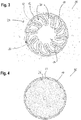
- FIG. 2 an aperture 24 is shown in a wall 26 through which a tube 28 or conduit passes.
- the tube 28 does not completely fill the opening 24, so that a gap is created between the tube 28 and an inner wall 30 of the opening 24. In this gap, the intumescent fire protection device 10 is arranged.
- FIG. 2 only the base portion 12 and the fins 14 of the intumescent fire protection device 10 shown and not even the coating 22nd
- the intumescent fire protection device 10 was then inserted into the gap in the aperture 24 so that the base portion 12 forms a ring.
- the base portion 12 lies with its longitudinal surface 16, on which no fins 14 are provided on the inner wall 30 at.
- the fins 14 extend from the inner wall 30 facing away from the longitudinal surface 16 partially radially inwardly and thus on the radially inner side of the base portion 12th
- the fins 14 are bent toward the base portion 12 and lie on the tube 28. In this position, the fins 14 are biased relative to the base portion 12.
- the tube 28 melts and collapses. It leaves behind a cavity in the opening 24, which is then completely surrounded by the intumescent fire protection device 10. Through the cavity then pulls hot smoke or even hit flames.
- the fins 14 move as soon as the tube 28 has been destroyed, due to their bias radially inwardly and extend into the cavity 28 produced by the tube in the opening 24th
- channels 31 are formed between the individual fins 14 in the intumescent fire protection device 10, then hit by the flames or the smoke pulls. Through the channels 31, the surface of the intumescent fire protection device 10 is increased, which can come into contact with the hot smoke or with the flames.
- the lamellae 14 are pressed by the onset of intumescence in the cavity, since the coating 22 or the material of the fins 14 inflates. Thus, at the latest then the channels 31 are formed.
- louvers 14 may, by virtue of the force generated by the intumescence, over their too FIG. 1 described rest position are bent away from the base portion 12 so that they partially protrude almost perpendicularly from the base portion 12 into the cavity.
- the channels 31 are further increased, whereby the surface of the intumescent fire protection device 10, the smoke or Fire comes into contact, is further increased.
- a self-reinforcing effect is achieved, which leads to a rapid swelling of the fins 14 and the base portion 12 and the coating 22.
- the lamellae 14 and the base section 12 or the intumescent coating 22 thus expands rapidly, until finally the entire opening 24 is closed and, if appropriate, the lamellae 14 are also surrounded by the coating 22.
- FIG. 4 For example, a situation just prior to the complete closure of the aperture 24 is shown using the example of a coated intumescent fire protection device 10.
- a substantially cuboidal semifinished product 32 made of the elastic intumescent material of the base section 12 or of the lamellae 14 can be provided by extrusion ( FIG. 5a ).
- a slot are introduced, which extends along the longitudinal direction L of the cuboid semi-finished product 32.
- the slit viewed in the transverse direction Q, describes a comb-like shape that is rotationally symmetrical about an axis in the transverse direction Q.
- the slot extends along the entire longitudinal extension and the entire width B of the semifinished product 32.
- the semi-finished product 32 is divided into two main body 34, each already having a base portion 12 and fins 14 (see FIG. 5b ).
- the two base bodies 34 are at the same time also the finished intumescent fire protection devices 10.
- the main body 34 In the case that the semifinished product 32 was not already made of an intumescent material, the main body 34 must still be coated.
- FIGS. 6 and 7 Further embodiments of an intumescent fire protection device 10 are shown, which substantially correspond to the first embodiment of the intumescent fire protection device 10. In the following, therefore, only the differences will be discussed, wherein identical and functionally identical parts are provided with the same reference numerals.
- FIG. 6 a second embodiment of the intumescent fire protection device 10 is shown.
- the fins 14 extend in this second embodiment, all of the same longitudinal edge 18 of the base portion 12 and have the same thickness D as the base portion 12th
- the base portion 12 and the fins 14 may be provided on both of their longitudinal surfaces 16 with the coating 22. It is also conceivable that they are only provided on one of their longitudinal surfaces 16 with the coating 22, in which case the length of the base portion 12 must be selected so long that the base portion 12 can run in two layers in the gap between the tube 28 and inner wall 30.
- a band-shaped body of thickness D corresponding to the thickness of the base portion 12 and the fins 14 may be extruded.
- This base body is then cut at regular intervals along the longitudinal axis L in the transverse direction Q, in order to form the individual lamellae 14 on the longitudinal edge 18.
- the intumescent fire protection device 10 is not made in one piece, but consists of a plurality of plate-shaped supports 36th
- the carriers 36 are arranged partially overlapping and attached to one another on one side, for example by means of staples 38 or a seam. Each of the carriers 36 forms both a part of the base section 12 and a lamella 14.
- each blade 14 is formed integrally with a part of the base portion 12.
- the base portion 12 is made in each case band-shaped and can be cut to the required length.
- the base portion 12 is already a ring with a predetermined diameter, wherein the fins 14 then extend radially inwardly.
- the longitudinal direction L of the base portion corresponds in this case to the circumferential direction of the ring.
Landscapes
- Engineering & Computer Science (AREA)
- General Engineering & Computer Science (AREA)
- Mechanical Engineering (AREA)
- Building Environments (AREA)
Priority Applications (2)
| Application Number | Priority Date | Filing Date | Title |
|---|---|---|---|
| EP16200513.6A EP3327327A1 (fr) | 2016-11-24 | 2016-11-24 | Dispositif coupe-feu intumescent, percé dans une paroi ou un plafond et procédé de fabrication de dispositifs coupe-feu intumescents |
| EP17200970.6A EP3327328A1 (fr) | 2016-11-24 | 2017-11-10 | Dispositif coupe-feu intumescent, percé dans une paroi ou un plafond et procédé de fabrication de dispositifs coupe-feu intumescents |
Applications Claiming Priority (1)
| Application Number | Priority Date | Filing Date | Title |
|---|---|---|---|
| EP16200513.6A EP3327327A1 (fr) | 2016-11-24 | 2016-11-24 | Dispositif coupe-feu intumescent, percé dans une paroi ou un plafond et procédé de fabrication de dispositifs coupe-feu intumescents |
Publications (1)
| Publication Number | Publication Date |
|---|---|
| EP3327327A1 true EP3327327A1 (fr) | 2018-05-30 |
Family
ID=57406086
Family Applications (2)
| Application Number | Title | Priority Date | Filing Date |
|---|---|---|---|
| EP16200513.6A Withdrawn EP3327327A1 (fr) | 2016-11-24 | 2016-11-24 | Dispositif coupe-feu intumescent, percé dans une paroi ou un plafond et procédé de fabrication de dispositifs coupe-feu intumescents |
| EP17200970.6A Withdrawn EP3327328A1 (fr) | 2016-11-24 | 2017-11-10 | Dispositif coupe-feu intumescent, percé dans une paroi ou un plafond et procédé de fabrication de dispositifs coupe-feu intumescents |
Family Applications After (1)
| Application Number | Title | Priority Date | Filing Date |
|---|---|---|---|
| EP17200970.6A Withdrawn EP3327328A1 (fr) | 2016-11-24 | 2017-11-10 | Dispositif coupe-feu intumescent, percé dans une paroi ou un plafond et procédé de fabrication de dispositifs coupe-feu intumescents |
Country Status (1)
| Country | Link |
|---|---|
| EP (2) | EP3327327A1 (fr) |
Citations (4)
| Publication number | Priority date | Publication date | Assignee | Title |
|---|---|---|---|---|
| DE202010007623U1 (de) * | 2010-06-04 | 2011-10-05 | Doyma Gmbh & Co | Brandschutzvorrichtung |
| DE102011105575B3 (de) * | 2011-06-25 | 2012-09-06 | Kaiser Gmbh & Co. Kg | Elektrische Installationsdose |
| EP2572760A2 (fr) * | 2011-09-20 | 2013-03-27 | HILTI Aktiengesellschaft | Manchette pare-feu |
| EP2682657A1 (fr) * | 2012-07-03 | 2014-01-08 | HILTI Aktiengesellschaft | Manchette pare-feu |
-
2016
- 2016-11-24 EP EP16200513.6A patent/EP3327327A1/fr not_active Withdrawn
-
2017
- 2017-11-10 EP EP17200970.6A patent/EP3327328A1/fr not_active Withdrawn
Patent Citations (4)
| Publication number | Priority date | Publication date | Assignee | Title |
|---|---|---|---|---|
| DE202010007623U1 (de) * | 2010-06-04 | 2011-10-05 | Doyma Gmbh & Co | Brandschutzvorrichtung |
| DE102011105575B3 (de) * | 2011-06-25 | 2012-09-06 | Kaiser Gmbh & Co. Kg | Elektrische Installationsdose |
| EP2572760A2 (fr) * | 2011-09-20 | 2013-03-27 | HILTI Aktiengesellschaft | Manchette pare-feu |
| EP2682657A1 (fr) * | 2012-07-03 | 2014-01-08 | HILTI Aktiengesellschaft | Manchette pare-feu |
Also Published As
| Publication number | Publication date |
|---|---|
| EP3327328A1 (fr) | 2018-05-30 |
Similar Documents
| Publication | Publication Date | Title |
|---|---|---|
| EP3289265B1 (fr) | Manchette coupe-feu | |
| EP2572760A2 (fr) | Manchette pare-feu | |
| EP1847748A2 (fr) | Tuyau flexible de protection coupe-feu | |
| DE102014108757A1 (de) | Wellrohr aus Kunststoff zum Ummanteln von Leitungen sowie Verfahren zur Herstellung eines solchen Wellrohres | |
| DE102011084056A1 (de) | Halter für eine Brandschutzmanschette und Verwendung dieses Halters | |
| EP3088784A1 (fr) | Manchette coupe-feu | |
| DE2142837A1 (de) | Schwer entflammbare Dichtungen | |
| DE202016104450U1 (de) | Rohrleitungssystem | |
| EP3289267B1 (fr) | Manchette coupe-feu | |
| DE2546918A1 (de) | Vorrichtung zur aufnahme eines reifenaufbaus bei der laufflaechenerneuerung mittels eines vorgepraegten laufflaechenbandes | |
| EP3586049B1 (fr) | Élement ignifuge | |
| EP3327328A1 (fr) | Dispositif coupe-feu intumescent, percé dans une paroi ou un plafond et procédé de fabrication de dispositifs coupe-feu intumescents | |
| DE102013018352A1 (de) | Profilschiene | |
| WO2017220357A1 (fr) | Élément coupe-feu pour l'étanchéification d'ouvertures de passage dans des éléments structuraux | |
| DE102015105651A1 (de) | Dichtungselement für einen Lüftungskanal | |
| EP3246608A1 (fr) | Élement ignifuge et procede de fabrication d'un element ignifuge | |
| EP3544691B1 (fr) | Dispositif coupe-feu intumescent et percée dans une paroi | |
| DE2016305C3 (de) | Überwachungseinrichtung einer Überzugskabine | |
| DE102015218341B4 (de) | Verfahren zur Verringerung einer unerwünschten Wärmeabgabe von Heizrohren einer Flächenheizung | |
| WO2018219730A1 (fr) | Élément coupe-feu et bandage coupe-feu | |
| DE102013101467A1 (de) | Spiraltellerfeder | |
| EP3894730B1 (fr) | Segment de manchon ignifuge et manchon ignifuge | |
| DE4326883A1 (de) | Verfahren und Vorrichtung zum Verschließen von Wand- oder Deckenöffnungen im Brandfall | |
| DE3108921C2 (de) | Feuerschutz-Absperrvorrichtung für einen Luftkanal | |
| WO2020120107A1 (fr) | Élément ignifuge comprenant un bimétal |
Legal Events
| Date | Code | Title | Description |
|---|---|---|---|
| PUAI | Public reference made under article 153(3) epc to a published international application that has entered the european phase |
Free format text: ORIGINAL CODE: 0009012 |
|
| AK | Designated contracting states |
Kind code of ref document: A1 Designated state(s): AL AT BE BG CH CY CZ DE DK EE ES FI FR GB GR HR HU IE IS IT LI LT LU LV MC MK MT NL NO PL PT RO RS SE SI SK SM TR |
|
| AX | Request for extension of the european patent |
Extension state: BA ME |
|
| STAA | Information on the status of an ep patent application or granted ep patent |
Free format text: STATUS: THE APPLICATION IS DEEMED TO BE WITHDRAWN |
|
| 18D | Application deemed to be withdrawn |
Effective date: 20181201 |