EP3327338A1 - Lichtstrahlanpassungsvorrichtung, optische anordnung und beleuchtungs- und/oder signalisierungsvorrichtung - Google Patents
Lichtstrahlanpassungsvorrichtung, optische anordnung und beleuchtungs- und/oder signalisierungsvorrichtung Download PDFInfo
- Publication number
- EP3327338A1 EP3327338A1 EP17201193.4A EP17201193A EP3327338A1 EP 3327338 A1 EP3327338 A1 EP 3327338A1 EP 17201193 A EP17201193 A EP 17201193A EP 3327338 A1 EP3327338 A1 EP 3327338A1
- Authority
- EP
- European Patent Office
- Prior art keywords
- light
- light beam
- converging
- focal
- adjusting device
- Prior art date
- Legal status (The legal status is an assumption and is not a legal conclusion. Google has not performed a legal analysis and makes no representation as to the accuracy of the status listed.)
- Withdrawn
Links
Images


Classifications
-
- G—PHYSICS
- G02—OPTICS
- G02B—OPTICAL ELEMENTS, SYSTEMS OR APPARATUS
- G02B3/00—Simple or compound lenses
- G02B3/10—Bifocal lenses; Multifocal lenses
-
- F—MECHANICAL ENGINEERING; LIGHTING; HEATING; WEAPONS; BLASTING
- F21—LIGHTING
- F21V—FUNCTIONAL FEATURES OR DETAILS OF LIGHTING DEVICES OR SYSTEMS THEREOF; STRUCTURAL COMBINATIONS OF LIGHTING DEVICES WITH OTHER ARTICLES, NOT OTHERWISE PROVIDED FOR
- F21V5/00—Refractors for light sources
-
- F—MECHANICAL ENGINEERING; LIGHTING; HEATING; WEAPONS; BLASTING
- F21—LIGHTING
- F21V—FUNCTIONAL FEATURES OR DETAILS OF LIGHTING DEVICES OR SYSTEMS THEREOF; STRUCTURAL COMBINATIONS OF LIGHTING DEVICES WITH OTHER ARTICLES, NOT OTHERWISE PROVIDED FOR
- F21V13/00—Producing particular characteristics or distribution of the light emitted by means of a combination of elements specified in two or more of main groups F21V1/00 - F21V11/00
- F21V13/02—Combinations of only two kinds of elements
- F21V13/04—Combinations of only two kinds of elements the elements being reflectors and refractors
-
- F—MECHANICAL ENGINEERING; LIGHTING; HEATING; WEAPONS; BLASTING
- F21—LIGHTING
- F21V—FUNCTIONAL FEATURES OR DETAILS OF LIGHTING DEVICES OR SYSTEMS THEREOF; STRUCTURAL COMBINATIONS OF LIGHTING DEVICES WITH OTHER ARTICLES, NOT OTHERWISE PROVIDED FOR
- F21V5/00—Refractors for light sources
- F21V5/04—Refractors for light sources of lens shape
- F21V5/045—Refractors for light sources of lens shape the lens having discontinuous faces, e.g. Fresnel lenses
-
- F—MECHANICAL ENGINEERING; LIGHTING; HEATING; WEAPONS; BLASTING
- F21—LIGHTING
- F21V—FUNCTIONAL FEATURES OR DETAILS OF LIGHTING DEVICES OR SYSTEMS THEREOF; STRUCTURAL COMBINATIONS OF LIGHTING DEVICES WITH OTHER ARTICLES, NOT OTHERWISE PROVIDED FOR
- F21V7/00—Reflectors for light sources
- F21V7/0025—Combination of two or more reflectors for a single light source
-
- F—MECHANICAL ENGINEERING; LIGHTING; HEATING; WEAPONS; BLASTING
- F21—LIGHTING
- F21V—FUNCTIONAL FEATURES OR DETAILS OF LIGHTING DEVICES OR SYSTEMS THEREOF; STRUCTURAL COMBINATIONS OF LIGHTING DEVICES WITH OTHER ARTICLES, NOT OTHERWISE PROVIDED FOR
- F21V7/00—Reflectors for light sources
- F21V7/0091—Reflectors for light sources using total internal reflection
-
- G—PHYSICS
- G02—OPTICS
- G02B—OPTICAL ELEMENTS, SYSTEMS OR APPARATUS
- G02B27/00—Optical systems or apparatus not provided for by any of the groups G02B1/00 - G02B26/00, G02B30/00
- G02B27/30—Collimators
-
- G—PHYSICS
- G02—OPTICS
- G02B—OPTICAL ELEMENTS, SYSTEMS OR APPARATUS
- G02B3/00—Simple or compound lenses
- G02B3/02—Simple or compound lenses with non-spherical faces
- G02B3/08—Simple or compound lenses with non-spherical faces with discontinuous faces, e.g. Fresnel lens
-
- F—MECHANICAL ENGINEERING; LIGHTING; HEATING; WEAPONS; BLASTING
- F21—LIGHTING
- F21S—NON-PORTABLE LIGHTING DEVICES; SYSTEMS THEREOF; VEHICLE LIGHTING DEVICES SPECIALLY ADAPTED FOR VEHICLE EXTERIORS
- F21S41/00—Illuminating devices specially adapted for vehicle exteriors, e.g. headlamps
- F21S41/20—Illuminating devices specially adapted for vehicle exteriors, e.g. headlamps characterised by refractors, transparent cover plates, light guides or filters
-
- F—MECHANICAL ENGINEERING; LIGHTING; HEATING; WEAPONS; BLASTING
- F21—LIGHTING
- F21S—NON-PORTABLE LIGHTING DEVICES; SYSTEMS THEREOF; VEHICLE LIGHTING DEVICES SPECIALLY ADAPTED FOR VEHICLE EXTERIORS
- F21S43/00—Signalling devices specially adapted for vehicle exteriors, e.g. brake lamps, direction indicator lights or reversing lights
- F21S43/20—Signalling devices specially adapted for vehicle exteriors, e.g. brake lamps, direction indicator lights or reversing lights characterised by refractors, transparent cover plates, light guides or filters
- F21S43/26—Refractors, transparent cover plates, light guides or filters not provided in groups F21S43/235 - F21S43/255
-
- F—MECHANICAL ENGINEERING; LIGHTING; HEATING; WEAPONS; BLASTING
- F21—LIGHTING
- F21V—FUNCTIONAL FEATURES OR DETAILS OF LIGHTING DEVICES OR SYSTEMS THEREOF; STRUCTURAL COMBINATIONS OF LIGHTING DEVICES WITH OTHER ARTICLES, NOT OTHERWISE PROVIDED FOR
- F21V2200/00—Use of light guides, e.g. fibre optic devices, in lighting devices or systems
Definitions
- the present application relates to the lighting and signaling field, and in particular to a light beam adjusting device, an optical assembly and a lighting and/or signaling apparatus including the optical assembly.
- a lighting or signaling apparatus that can only provide a function of illumination or a function of signal indicator will not satisfy the requirements of the people any longer. Instead, more and more customized applications of the lighting or signaling apparatus (for example a vehicle lamp for an automobile vehicle) have been proposed, therefore it needs to provide more diverse patterns and lit aspects of the light beam. In this case, a single light source often cannot satisfy the requirements. Thus, in order to achieve the diverse lit aspects (such as diverse depths of field, plural spots), in the prior art, more light sources are often needed to be provided. Thus, more light sources typically will occupy more space. It will affect the design space of lamps adversely and limit style design.
- the present application is intended to provide a light beam adjusting device that can focus a light beam at a plurality of focal points to use a single light source to provide a lit aspect similar to that of a combination of a plurality of light sources.
- the present application is also intended to provide an optical assembly including the light beam adjusting device and a lighting and/or signaling apparatus.
- An embodiment of present application provides a light beam adjusting device including: a light collimating portion arranged to collimate a light beam; and a multi-focal converging portion arranged to converge the collimated light beam, the multi-focal converging portion including two or more converging surfaces, wherein at least two of the two or more converging surfaces have focal points separated spatially from each other.
- all of focal points of the two or more converging surfaces are arranged in the same axis of the multi-focal converging portion.
- the two or more converging surfaces are arranged in sequence along a radial direction of the multi-focal converging portion.
- all of focal points of the two or more converging surfaces are arranged in the same plane perpendicular to an axis of the multi-focal converging portion.
- all of peaks of the two or more converging surfaces are arranged in the same plane perpendicular to the axis of the multi-focal converging portion.
- all of focal points of the two or more converging surfaces are arranged in at least two different planes perpendicular to an axis of the multi-focal converging portion respectively.
- all of peaks of the two or more converging surfaces are arranged in the at least two different planes perpendicular to the axis of the multi-focal converging portion respectively.
- the light collimating portion and the multi-focal converging portion are formed integrally as one single part, and the light collimating portion is formed at a light incidence side of the single part and the multi-focal converging portion is formed at a light exit side of the single part.
- the light beam adjusting device further includes a reflector arranged to reflect a light emitted from the two or more converging surfaces.
- the two or more converging surfaces are arranged at a side surface of the single part, and the single part further comprises a reflective face arranged to direct the light beam collimated by the light collimating portion to the two or more converging surfaces, the reflective face being arranged at a side of the single part opposite to the light collimating portion.
- the light beam adjusting device further includes a plurality of mirrors arranged outside the side surface of the single part and arranged in sequence from near to far with respect to the side surface of the single part, to reflect the light beam converged by the two or more converging surfaces respectively.
- the light collimating portion comprises a first light incident face, a second light incident face and a totally reflective face, and wherein the first light incident face is arranged at an intermediate position of the light collimating portion to collimate a central portion of the light beam; the second light incident face is arranged outside the first light incident face in a radial direction to direct a peripheral portion of the light beam to the totally reflective face which is arranged outside the second light incident face in a radial direction to collimate the portion of the light beam incident from the second light incident face.
- An embodiment of the present application provides an optical assembly comprising: a light source arranged to emit a light beam; and the light beam adjusting device as described in any one of the above embodiments.
- the optical assembly further includes a light guide device which has a light incidence end arranged toward the two or more converging surfaces and arranged to receive the light emitted from the two or more converging surfaces.
- An embodiment of the present application also provides a lighting and/or signaling apparatus, including the optical assembly as described in any one of the above embodiments.
- the intensity distribution of a light beam emitted from a single light source can be converted by a plurality of converging surfaces having different focal points into an intensity distribution similar to that of the light beams emitted from a plurality of light sources, so as to improve the lit aspect of the illuminating and/or signaling light of a vehicle lamp.
- a light beam adjusting device including: a light collimating portion arranged to collimate a light beam; and a multi-focal converging portion arranged to converge the collimated light beam, the multi-focal converging portion including two or more converging surfaces, wherein at least two of the two or more converging surfaces have focal points separated spatially from each other.
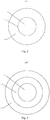
- Figs. 1-3 are schematic views showing a light beam adjusting device 100 according to an embodiment of the present application.
- the light beam adjusting device 100 includes: a light collimating portion 10 and a multi-focal converging portion 20.
- the light collimating portion 10 is arranged to collimate a light beam 30(for example, emitted from a light source 40).
- the multi-focal converging portion 20 is arranged to converge the collimated light beam.
- the multi-focal converging portion 20 includes three converging surfaces 21, 22, 23.
- the three converging surfaces 21, 22, 23 have focal points separated spatially from each other. As illustrated in Fig. 3 , these focal points are located at three points F1, F2 and F3.
- the focal points F1, F2 and F3 may be considered as virtual source points.
- the light beam 30 when viewed in a direction opposite to the light exit direction of the light beam adjusting device 100 (i.e., viewed from right to left at the right side of F3 in the example shown in Fig. 3 ), the light beam 30 seems to be converted into a combination of light beams emitted from focal points (or virtual source points) F1, F2 and F3 after it passes through the light beam adjusting device 100.
- the light beam adjusting device 100 can provide lit aspect similar to that of a combination of a plurality of point light sources by a single point light source.
- the number of the converging surfaces is not limited to three.
- two or more than three converging surfaces may be provided. At least two of these converging surfaces have focal points separated spatially from each other. In this way, it may achieve the lit aspect similar to that of the combination of a plurality of point light sources.
- all of focal points F1, F2, F3 of the three converging surfaces 21, 22, 23 are arranged in the same axis y of the multi-focal converging portion 20.
- the converging surfaces 21, 22, 23 may be arranged in sequence in a radial direction of the multi-focal converging portion 20. In this way, the focal points of the converging surfaces 21, 22, 23 may be separated from each other in the axis y by adjusting the shape and position of each of the converging surfaces 21, 22, 23.
- the converging surfaces 21, 22, 23 are shown as concentric circles and circular rings in shape.
- the converging surfaces 21, 22, 23 may have other forms or structures as long as it allows the focal points of the three converging surfaces 21, 22, 23 to be in the same axis.
- the lit aspect of the single point light source may be converted into a light aspect similar to that of the combination of the plurality of point light sources located in the same axis.
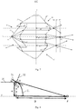
- Fig. 8 shows schematically converging effects of the light beam 30 at any position on the converging surfaces 21, 22, 23.
- the numeral "31" represents a tangent line to the converging surface 21, 22, 23 at a position and the numeral "32" represents a normal line to the converging surface 21, 22, 23 at the position.
- ⁇ is an angle between an incident light and the tangent line 31 at the position.
- ⁇ is an angle between an emergent light and a plane perpendicular to the axis y of the multi-focal converging portion 20 at the position.
- ⁇ is an angle between an emergent light and the normal line 32 at the position.
- N1 is a refractive index of a medium at an inside of the converging surface 21, 22, 23(i.e., the material medium of the multi-focal converging portion 20, such as PMMA (refractive index of 1.49) or polycarbonate (refractive index of 1.586)).
- N2 is a refractive index of a medium at an outside of the converging surface 21, 22, 23(i.e., the external environmental medium, such as air).
- H is a height between this position and the axis y of the multi-focal converging portion 20.
- D is a distance between this position and the focal point F along the axis y. In practice, H and D may be given as requirements of design.
- the angles ⁇ , ⁇ and ⁇ can be obtained. That is, the respective angles of desired incident light and emergent light with respect to the tangent line 31 and the normal line 32 can be obtained. In this way, the surface shapes of the converging surface 21, 22, 23 at respective positions can be determined.
- the angle ⁇ may be in a range between 47 degrees and 60 degrees; for polycarbonate, the angle ⁇ may be in a range between 50 degrees and 65 degrees.
- H may be in a range between 3mm and 10mm, such as 5mm.
- D may be in a range between 6mm and 20mm, such as 9.7mm.
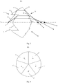
- Fig. 4 and Fig. 5 show schematically a light beam adjusting device 100' according to another embodiment of the present application.
- the embodiment is distinguished from those shown in Figs. 1-3 in that focal points F1', F2' of the converging surfaces 21', 22', 23', 24', 25' are arranged in the same plane K perpendicular to the axis y of the multi-focal converging portion 20.
- Fig. 5 only shows focal points of two converging surfaces 21', 22'. However, the focal points of the converging surfaces 23', 24', 25' may also be arranged in the plane K).
- the converging surfaces 21', 22', 23', 24', 25' may have peaks (i.e., the highest points projecting from the respective converging surfaces 21', 22', 23', 24', 25') P1, P2, P3, P4, P5. All of peaks P1, P2, P3, P4, P5 of the respective converging surfaces 21', 22', 23', 24', 25' may also be arranged in the same plane perpendicular to the axis y of the multi-focal converging portion 20.
- the distance D1' between the peak P1 and a plane Z perpendicular to the axis y is equal to the distance D2' between the peak P2 and the plane Z perpendicular to the axis y, that is, these peaks are located in the same plane perpendicular to the axis y of the multi-focal converging portion 20.
- the converging surfaces 21', 22', 23', 24', 25' are shown to occupy the same area of circular sector respectively.
- embodiments of the present application are not limited to this.
- other forms of the converging surfaces 21', 22', 23', 24', 25' may also be applied as long as the focal points of the converging surfaces 21', 22', 23', 24', 25' can be arranged in the same plane perpendicular to the axis y of the multi-focal converging portion 20.
- the lit aspect of the single point light source may be converted into a light aspect similar to that of the combination of the plurality of point light sources located in the same plane.
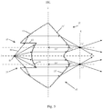
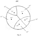
- Fig. 6 and Fig. 7 show schematically a light beam adjusting device 100" according to a further embodiment of the present application.
- the embodiment is distinguished from those shown in Figs. 1-3 in that focal points of the converging surfaces 21", 22", 23", 24", 25" are arranged in two different planes perpendicular to the axis y of the multi-focal converging portion 20. That is, they are not arranged in the same plane perpendicular to the axis y of the multi-focal converging portion 20. (For the sake of clarity, Fig.
- the converging surfaces 21", 22", 23", 24", 25 may have peaks (i.e., the highest points projecting from the respective converging surfaces 21", 22", 23", 24", 25") P1", P2", P3", P4", P5". All of these peaks P1", P2", P3", P4", P5" of the respective converging surfaces 21", 22", 23", 24", 25” may also be arranged in at least two different planes perpendicular to the axis y of the multi-focal converging portion 20. That is, these peaks P1", P2", P3", P4", P5" are also not located in the same plane.
- any one of the distance D1 between the peak P1" and a plane Z perpendicular to the axis y, the distance D2 between the peak P2" and the plane Z perpendicular to the axis y and the distance D3 between the peak P3" and the plane Z perpendicular to the axis y is not equal to the other two of them.
- the focal points F1", F2", F3" of the converging surfaces 21", 22", 23" are arranged in planes K1, K2, K3 perpendicular to the axis y of the multi-focal converging portion 20, respectively.
- the distances between these peaks P1", P2", P3", P4", P5" and the axis y may also be arranged in any manner as requirement of design. Such arrangement provides more flexible design for configuration of the focal points of the light beam (or virtual source points). In practice, the number and shape of the converging surfaces may be designed freely as requirement of the design.
- the lit aspect of the single point light source may be converted into a light aspect similar to that of the combination of the plurality of point light sources arranged in any manner. It may provide more freedom for the design of the lit aspect of lamps.
- the arrangement of the focal points in the same axis can provide the maximum optical efficiency (for example up to 90%) for the light beam adjusting device 100, 100', 100" while the arrangement of the focal points in the same plane and the arrangement of the focal points in different planes may provide off-axis illumination effects.
- the surface shapes of the converging surfaces 21', 22', 23', 24', 25', 21", 22", 23", 24", 25" may be determined by means of the method shown in Fig. 8 . The details will be omitted herein.
- the light collimating portion 10 may for example have a first light incident face 11, a second light incident face 12 and a totally reflective face 13.
- the first light incident face 11 is located in an intermediate position of the light collimating portion 10 and is configured to collimate a central portion of the light beam 30.
- the second light incident face 12 is arranged outside the first light incident face 11 in a radial direction and configured to direct (for example deflect) a peripheral portion of the light beam 30 to the totally reflective face 13.
- the totally reflective face 13 is arranged outside the second light incident face 12 in a radial direction and configured to collimate the portion of the light beam incident from the second light incident face 12.
- Such structure of the light collimating portion 10 can allow the position of the light source 40 to be closer to the light collimating portion 10, so as to improve the optical efficiency and reduce the size of the lamps.
- the embodiments of the present application are not limited to this.
- any other forms of the light collimating portion 10 may also be applied.
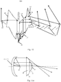
- the reflective collimator 10' shown in Fig. 11a e.g., it has a curve surface shape such as paraboloid
- the transmissive collimator 10" shown in Fig. 11b may be used as the light collimating portion 10.
- the light source 40 may be arranged between the light collimating portion 10 and the multi-focal converging portion 20.
- the light collimating portion 10 and the multi-focal converging portion 20 may be formed integrally as one single part.
- the light collimating portion 10 is formed at a light incidence side 51 of the single part and the multi-focal converging portion 20 is formed at a light exit side 52 of the single part.
- Forming the light collimating portion 10 and the multi-focal converging portion 20 as one integral part may reduce the space that the light beam adjusting device occupies and save the costs and reduce work load of calibrating optical paths.
- the thickness of the multi-focal converging portion 20 (for example the maximum height of the peaks of the converging surfaces) may be less than the thickness of the light collimating portion 10, so as to further reduce the size of the single part.
- the light beam adjusting device 200 may further include a reflector 60, for example, a planar mirror or a curved mirror (e.g., it has a shape such as paraboloid, ellipsoid, hyperboloid) arranged to reflect a light emitted from the converging surfaces 21, 22, 23.
- a reflector 60 may be arranged outside the multi-focal converging portion 20. Due to difference in focal points of the converging surfaces 21, 22, 23, the light reflected by the reflector 60 may provide different depth of field.
- Fig. 10 shows a light beam adjusting device 300 according to still further embodiment of the present application.
- the converging surfaces 26, 27, 28 are arranged at a side surface 53 of the single part formed integrally by the light collimating portion 10 and the multi-focal converging portion 20.
- the single part further includes a reflective face 54 arranged to direct the light beam collimated by the light collimating portion 10 to the converging surfaces 26, 27, 28.
- the reflective face 54 is arranged at the side of the single part opposite to the light collimating portion 10. By means of the reflective face 54, the light converged by the converging surfaces 26, 27, 28 is directed towards periphery of the light beam adjusting device 300 to enlarge the propagation range.
- the light beam adjusting device 300 may further include a plurality of mirrors 70 arranged outside the side surface 53 of the single part and arranged in sequence from near to far with respect to the side surface 53 of the single part, to reflect the light beam converged by these converging surfaces 26, 27, 28 respectively. Since the converging surfaces 26, 27, 28 have different focal points respectively, the light reflected by the plurality of mirrors 70 may provide more diverse lit aspect.
- the orientations of the plurality of mirrors 70 may be provided as requirement of the design of optical paths, for example, the plurality of mirrors 70 may have the same orientation or different orientations from each other, as shown in Fig. 10.
- Fig. 10 also shows another surface 29 in opposite to the converging surfaces 26, 27, 28.
- the surface 29 may have different converging characteristic from those of the converging surfaces 26, 27, 28, such that the light emitted from the light source 40 can have different travel directions or converging degrees on different sides of the light beam adjusting device 300. It may provide more flexibility for the design of the optical paths.
- An embodiment of the present application also provides an optical assembly 500.
- the optical assembly 500 includes: a light source arranged to emit a light beam 30; and the light beam adjusting device 100, 100', 100", 200, 300 as described in any one of the above embodiments.
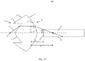
- the optical assembly 500 may further include a light guide device 80 which has a light incidence end 81 arranged toward the converging surfaces 21, 22, 23 and arranged to receive the light emitted from the converging surfaces 21, 22, 23.
- Fig. 13 shows an exemplary structure of the light guide device 80.
- the light guide device 80 has an axis coinciding with the axis of the light beam adjusting device 100. It is assumed that R is the radius of the end face of the light incident end 81 of the light guide device 80, F1 is a focal point of an optional converging surface 21, D1 is a distance between a position A on the converging surface 21 and the light incident end 81 in an axial direction of the light beam adjusting device 100, D2 is a distance between the position A on the converging surface 21 and the focal point F1 in the axial direction of the light beam adjusting device 100, and H is the height of the position A with respect to the axis of the light beam adjusting device 100.
- R is the radius of the end face of the light incident end 81 of the light guide device 80
- F1 is a focal point of an optional converging surface 21
- D1 is a distance between a position A on the converging surface 21 and the light incident end 81
- the radius R of the end face of the light incident end 81 of the light guide device 80 may be set depending on the positions of point on the converging surfaces 21, 22, 23. In order that all of lights from different converging surfaces can enter the light guide device 80, it is desired that there are a plurality of points on the converging surfaces 21, 22, 23 located in the range of height H.
- H may be in a range between 3mm and 10mm, for example, 5mm.
- R may be in a range between 1mm and 5mm, for example, 2mm.
- D2 may be in a range between 5mm and 20mm, for example, 9.7mm.
- D1 may be in a range between 3mm and 15mm, for example, 6.7mm.
- the light that enters the light incident end 81 of the light guide device 80 will have more uniform distribution of intensity and direction.
- the term of "light guide device” means a device that can direct a transmission of light therein mainly by internally total reflection. It may have various shapes, for example, of cylinders (may be called as light guide rods), bars (may be called as light guide bars or lamp bars), plates (may be called as light guide plates), rings (may be called as light guide rings), and so on. Because the light guide device directs the light mainly by the internally total reflection, it has high optical efficiency and low optical loss.
- the light guide device 80 directs the light incident from the light incident end 81 of the light guide device 80 towards its light exit end.
- the light guide device 80 it typically needs the incident light to satisfy the total reflection condition at a side surface 82 of the light guide device 80, however, some decoupling structures (such as micro protrusions) may be provided at certain positions where the light is desired to exit on the side surface 82, so as to destroy the total reflection condition to allow the light to exit at the specified positions.
- some decoupling structures such as micro protrusions
- An embodiment of the present application also provides a lighting and/or signaling apparatus, including the optical assembly 500 as described in any one of the above embodiments.
- the number of the converging surfaces is exemplary. Two or more converging surfaces are applicable.
- various forms of multi-focal converging portion 20 for example those with multiple focal points arranged in the same axis shown in Fig. 2 and Fig. 3 , those with multiple focal points arranged in the same plane shown in Fig. 4 and Fig. 5 , those with multiple focal points arranged in different planes shown in Fig. 6 and Fig. 7 , may be combined with any examples of the light collimating portions 10, the reflector 60, the plurality of mirrors 70 and the light guide device 80, or the like given in the embodiments of the present application.
- the light source 40 may include a white light LED or a monochromatic light LED. Alternatively, it may also be any other known light sources in the art, such as an incandescent lamp.
- the light collimating portion 10 and the multi-focal converging portion 20 may be made from transparent glass, resin or plastic materials, for example, PMMA (polymethy methacrylate) or polycarbonate.
- the optical assembly 500 may be supported or suspended by any known suitable devices for holding optical elements, for example a supporting seat or a suspension arm.
- the lighting and/or signaling apparatus may include any types of illumination lamps and/or signaling lamps for an automobile vehicle, for example, headlamps, central high mounted stop lamps, turn indicators, position lamps, rear stop lamps and so on.
- the lighting and/or signaling apparatus may also be used in any fields other than the vehicle lamps, for example, streetlamps, advertising lamps and so on.
Landscapes
- Physics & Mathematics (AREA)
- Engineering & Computer Science (AREA)
- General Engineering & Computer Science (AREA)
- General Physics & Mathematics (AREA)
- Optics & Photonics (AREA)
- Non-Portable Lighting Devices Or Systems Thereof (AREA)
- Lighting Device Outwards From Vehicle And Optical Signal (AREA)
Priority Applications (1)
| Application Number | Priority Date | Filing Date | Title |
|---|---|---|---|
| EP20183629.3A EP3754253B1 (de) | 2016-11-24 | 2017-11-10 | Lichtstrahlanpassungsvorrichtung, optische anordnung und beleuchtungs- und/oder signalisierungsvorrichtung |
Applications Claiming Priority (1)
| Application Number | Priority Date | Filing Date | Title |
|---|---|---|---|
| CN201611050816.0A CN108375043B (zh) | 2016-11-24 | 2016-11-24 | 光束调整装置、光学组件与照明和/或信号指示装置 |
Related Child Applications (1)
| Application Number | Title | Priority Date | Filing Date |
|---|---|---|---|
| EP20183629.3A Division EP3754253B1 (de) | 2016-11-24 | 2017-11-10 | Lichtstrahlanpassungsvorrichtung, optische anordnung und beleuchtungs- und/oder signalisierungsvorrichtung |
Publications (1)
| Publication Number | Publication Date |
|---|---|
| EP3327338A1 true EP3327338A1 (de) | 2018-05-30 |
Family
ID=60331420
Family Applications (2)
| Application Number | Title | Priority Date | Filing Date |
|---|---|---|---|
| EP17201193.4A Withdrawn EP3327338A1 (de) | 2016-11-24 | 2017-11-10 | Lichtstrahlanpassungsvorrichtung, optische anordnung und beleuchtungs- und/oder signalisierungsvorrichtung |
| EP20183629.3A Active EP3754253B1 (de) | 2016-11-24 | 2017-11-10 | Lichtstrahlanpassungsvorrichtung, optische anordnung und beleuchtungs- und/oder signalisierungsvorrichtung |
Family Applications After (1)
| Application Number | Title | Priority Date | Filing Date |
|---|---|---|---|
| EP20183629.3A Active EP3754253B1 (de) | 2016-11-24 | 2017-11-10 | Lichtstrahlanpassungsvorrichtung, optische anordnung und beleuchtungs- und/oder signalisierungsvorrichtung |
Country Status (3)
| Country | Link |
|---|---|
| US (1) | US10365414B2 (de) |
| EP (2) | EP3327338A1 (de) |
| CN (1) | CN108375043B (de) |
Cited By (1)
| Publication number | Priority date | Publication date | Assignee | Title |
|---|---|---|---|---|
| WO2019227938A1 (zh) * | 2018-06-01 | 2019-12-05 | 深圳市绎立锐光科技开发有限公司 | 光源模组 |
Families Citing this family (4)
| Publication number | Priority date | Publication date | Assignee | Title |
|---|---|---|---|---|
| CN106443846B (zh) * | 2016-12-26 | 2018-05-08 | 京东方科技集团股份有限公司 | 透镜及其制作方法、背光面板和显示装置 |
| US10234101B2 (en) * | 2017-04-27 | 2019-03-19 | Hyundai Mobis Co., Ltd. | Optical device |
| US11112089B2 (en) | 2019-06-28 | 2021-09-07 | Signify Holding B.V. | Two stage optic for LED devices |
| CN211043831U (zh) * | 2019-12-19 | 2020-07-17 | 欧普照明股份有限公司 | 一种光学扩束镜和灯具 |
Citations (7)
| Publication number | Priority date | Publication date | Assignee | Title |
|---|---|---|---|---|
| EP0458508A2 (de) * | 1990-05-14 | 1991-11-27 | Iolab Corporation | Angepasste Fresnellinse für multifokale intraokulare und mikrochirurgische Anwendungen |
| JPH04316010A (ja) * | 1991-04-16 | 1992-11-06 | Seiko Epson Corp | 集光用フレネルレンズ |
| US20030215938A1 (en) * | 2002-05-16 | 2003-11-20 | Sandell Donald R. | Lens assembly for biological testing |
| US20070147041A1 (en) * | 2005-10-14 | 2007-06-28 | Kabushiki Kaisha Toshiba | Lighting system |
| WO2008021082A2 (en) * | 2006-08-16 | 2008-02-21 | Rpc Photonics, Inc. | Illumination devices |
| WO2011079856A1 (en) * | 2009-12-28 | 2011-07-07 | Pirelli & C. S.P.A. | Photovoltaic concentrator with optical stepped lens and optical stepped lens |
| WO2016166583A1 (en) * | 2015-04-17 | 2016-10-20 | Prakhyat ROOP | Diffractive-refractive lens |
Family Cites Families (1)
| Publication number | Priority date | Publication date | Assignee | Title |
|---|---|---|---|---|
| US5504544A (en) * | 1994-11-23 | 1996-04-02 | Minnesota Mining And Manufacturing Company | Projector with multiple lamp light source |
-
2016
- 2016-11-24 CN CN201611050816.0A patent/CN108375043B/zh active Active
-
2017
- 2017-11-10 EP EP17201193.4A patent/EP3327338A1/de not_active Withdrawn
- 2017-11-10 EP EP20183629.3A patent/EP3754253B1/de active Active
- 2017-11-24 US US15/821,928 patent/US10365414B2/en active Active
Patent Citations (7)
| Publication number | Priority date | Publication date | Assignee | Title |
|---|---|---|---|---|
| EP0458508A2 (de) * | 1990-05-14 | 1991-11-27 | Iolab Corporation | Angepasste Fresnellinse für multifokale intraokulare und mikrochirurgische Anwendungen |
| JPH04316010A (ja) * | 1991-04-16 | 1992-11-06 | Seiko Epson Corp | 集光用フレネルレンズ |
| US20030215938A1 (en) * | 2002-05-16 | 2003-11-20 | Sandell Donald R. | Lens assembly for biological testing |
| US20070147041A1 (en) * | 2005-10-14 | 2007-06-28 | Kabushiki Kaisha Toshiba | Lighting system |
| WO2008021082A2 (en) * | 2006-08-16 | 2008-02-21 | Rpc Photonics, Inc. | Illumination devices |
| WO2011079856A1 (en) * | 2009-12-28 | 2011-07-07 | Pirelli & C. S.P.A. | Photovoltaic concentrator with optical stepped lens and optical stepped lens |
| WO2016166583A1 (en) * | 2015-04-17 | 2016-10-20 | Prakhyat ROOP | Diffractive-refractive lens |
Cited By (1)
| Publication number | Priority date | Publication date | Assignee | Title |
|---|---|---|---|---|
| WO2019227938A1 (zh) * | 2018-06-01 | 2019-12-05 | 深圳市绎立锐光科技开发有限公司 | 光源模组 |
Also Published As
| Publication number | Publication date |
|---|---|
| US20180143355A1 (en) | 2018-05-24 |
| EP3754253A1 (de) | 2020-12-23 |
| EP3754253B1 (de) | 2025-02-26 |
| US10365414B2 (en) | 2019-07-30 |
| CN108375043B (zh) | 2021-02-23 |
| CN108375043A (zh) | 2018-08-07 |
Similar Documents
| Publication | Publication Date | Title |
|---|---|---|
| EP3456587B1 (de) | Lichtstrahleinstellvorrichtung, fahrzeuglampe und kraftfahrzeug | |
| US10480743B2 (en) | Light beam adjusting device and vehicle lamp assembly | |
| EP3754253B1 (de) | Lichtstrahlanpassungsvorrichtung, optische anordnung und beleuchtungs- und/oder signalisierungsvorrichtung | |
| JP5715982B2 (ja) | コリメータ組立体 | |
| EP3021043B1 (de) | Beleuchtungsvorrichtung und kraftfahrzeug mit einer darin montierten beleuchtungsvorrichtung | |
| US8864346B2 (en) | Lens-reflector combination for batwing light distribution | |
| EP2771730B1 (de) | Linse und beleuchtungsvorrichtung mit der linse | |
| US9297512B2 (en) | Light flux controlling member, light emitting device and illumination apparatus | |
| CN103968326A (zh) | 透镜和具有该透镜的照明装置 | |
| EP3677829B1 (de) | Primärlinse, lichtemittierende anordnung, lichtemittierendes system und scheinwerfer | |
| EP3887879B1 (de) | Optische vorrichtung zur veränderung der lichtverteilung | |
| EP3762646B1 (de) | Optische vorrichtung zur veränderung der lichtverteilung | |
| CN110500556B (zh) | 用于车灯的导光部件、用于机动车辆的车灯和机动车辆 | |
| US10234095B2 (en) | Lens and vehicle headlamp structure | |
| US20190346107A1 (en) | Automotive lighting system for vehicles | |
| CN109695853B (zh) | 照明装置和机动车辆 | |
| CN110207070B (zh) | 光导部件、车灯和机动车辆 | |
| CN218237316U (zh) | 光导装置、光学照射组件以及机动车辆 | |
| JP2025143052A (ja) | 光学レンズ、光源装置、照明装置および移動体 | |
| EP4476478A1 (de) | Optische vorrichtung zur änderung einer lichtverteilung | |
| WO2019069419A1 (ja) | 照明装置 |
Legal Events
| Date | Code | Title | Description |
|---|---|---|---|
| PUAI | Public reference made under article 153(3) epc to a published international application that has entered the european phase |
Free format text: ORIGINAL CODE: 0009012 |
|
| STAA | Information on the status of an ep patent application or granted ep patent |
Free format text: STATUS: THE APPLICATION HAS BEEN PUBLISHED |
|
| AK | Designated contracting states |
Kind code of ref document: A1 Designated state(s): AL AT BE BG CH CY CZ DE DK EE ES FI FR GB GR HR HU IE IS IT LI LT LU LV MC MK MT NL NO PL PT RO RS SE SI SK SM TR |
|
| AX | Request for extension of the european patent |
Extension state: BA ME |
|
| STAA | Information on the status of an ep patent application or granted ep patent |
Free format text: STATUS: REQUEST FOR EXAMINATION WAS MADE |
|
| 17P | Request for examination filed |
Effective date: 20181130 |
|
| RBV | Designated contracting states (corrected) |
Designated state(s): AL AT BE BG CH CY CZ DE DK EE ES FI FR GB GR HR HU IE IS IT LI LT LU LV MC MK MT NL NO PL PT RO RS SE SI SK SM TR |
|
| R17P | Request for examination filed (corrected) |
Effective date: 20181130 |
|
| RBV | Designated contracting states (corrected) |
Designated state(s): AL AT BE BG CH CY CZ DE DK EE ES FI FR GB GR HR HU IE IS IT LI LT LU LV MC MK MT NL NO PL PT RO RS SE SI SK SM TR |
|
| STAA | Information on the status of an ep patent application or granted ep patent |
Free format text: STATUS: EXAMINATION IS IN PROGRESS |
|
| 17Q | First examination report despatched |
Effective date: 20190409 |
|
| GRAP | Despatch of communication of intention to grant a patent |
Free format text: ORIGINAL CODE: EPIDOSNIGR1 |
|
| STAA | Information on the status of an ep patent application or granted ep patent |
Free format text: STATUS: GRANT OF PATENT IS INTENDED |
|
| INTG | Intention to grant announced |
Effective date: 20190930 |
|
| GRAJ | Information related to disapproval of communication of intention to grant by the applicant or resumption of examination proceedings by the epo deleted |
Free format text: ORIGINAL CODE: EPIDOSDIGR1 |
|
| STAA | Information on the status of an ep patent application or granted ep patent |
Free format text: STATUS: EXAMINATION IS IN PROGRESS |
|
| GRAP | Despatch of communication of intention to grant a patent |
Free format text: ORIGINAL CODE: EPIDOSNIGR1 |
|
| STAA | Information on the status of an ep patent application or granted ep patent |
Free format text: STATUS: GRANT OF PATENT IS INTENDED |
|
| INTC | Intention to grant announced (deleted) | ||
| INTG | Intention to grant announced |
Effective date: 20200703 |
|
| STAA | Information on the status of an ep patent application or granted ep patent |
Free format text: STATUS: THE APPLICATION IS DEEMED TO BE WITHDRAWN |
|
| 18D | Application deemed to be withdrawn |
Effective date: 20201114 |