EP3327353A1 - Dispositif de chauffage - Google Patents
Dispositif de chauffage Download PDFInfo
- Publication number
- EP3327353A1 EP3327353A1 EP17202837.5A EP17202837A EP3327353A1 EP 3327353 A1 EP3327353 A1 EP 3327353A1 EP 17202837 A EP17202837 A EP 17202837A EP 3327353 A1 EP3327353 A1 EP 3327353A1
- Authority
- EP
- European Patent Office
- Prior art keywords
- housing
- receptacle
- heating
- tablets
- opening
- Prior art date
- Legal status (The legal status is an assumption and is not a legal conclusion. Google has not performed a legal analysis and makes no representation as to the accuracy of the status listed.)
- Granted
Links
- 238000010438 heat treatment Methods 0.000 claims abstract description 118
- 239000003610 charcoal Substances 0.000 claims abstract description 53
- 239000007789 gas Substances 0.000 claims description 23
- 238000009423 ventilation Methods 0.000 claims description 18
- 239000003245 coal Substances 0.000 claims description 16
- 239000003054 catalyst Substances 0.000 claims description 14
- 238000004140 cleaning Methods 0.000 claims description 10
- QVGXLLKOCUKJST-UHFFFAOYSA-N atomic oxygen Chemical compound [O] QVGXLLKOCUKJST-UHFFFAOYSA-N 0.000 claims description 5
- 229910052760 oxygen Inorganic materials 0.000 claims description 5
- 239000001301 oxygen Substances 0.000 claims description 5
- 229910052500 inorganic mineral Inorganic materials 0.000 claims description 4
- 239000011707 mineral Substances 0.000 claims description 4
- OKTJSMMVPCPJKN-UHFFFAOYSA-N Carbon Chemical compound [C] OKTJSMMVPCPJKN-UHFFFAOYSA-N 0.000 claims description 3
- 229910052799 carbon Inorganic materials 0.000 claims description 3
- 239000011435 rock Substances 0.000 claims description 3
- 239000010410 layer Substances 0.000 description 10
- 238000000034 method Methods 0.000 description 6
- 239000002245 particle Substances 0.000 description 6
- 238000010586 diagram Methods 0.000 description 4
- 238000000926 separation method Methods 0.000 description 4
- 239000000463 material Substances 0.000 description 3
- 238000003466 welding Methods 0.000 description 3
- 241000208125 Nicotiana Species 0.000 description 2
- 235000002637 Nicotiana tabacum Nutrition 0.000 description 2
- 230000003213 activating effect Effects 0.000 description 2
- 238000004026 adhesive bonding Methods 0.000 description 2
- 239000002956 ash Substances 0.000 description 2
- 230000000295 complement effect Effects 0.000 description 2
- 238000005520 cutting process Methods 0.000 description 2
- 230000000694 effects Effects 0.000 description 2
- 238000004519 manufacturing process Methods 0.000 description 2
- 229910052751 metal Inorganic materials 0.000 description 2
- 239000002184 metal Substances 0.000 description 2
- 230000003287 optical effect Effects 0.000 description 2
- 235000002918 Fraxinus excelsior Nutrition 0.000 description 1
- 229910000831 Steel Inorganic materials 0.000 description 1
- 239000004809 Teflon Substances 0.000 description 1
- 229920006362 Teflon® Polymers 0.000 description 1
- 229910052782 aluminium Inorganic materials 0.000 description 1
- XAGFODPZIPBFFR-UHFFFAOYSA-N aluminium Chemical compound [Al] XAGFODPZIPBFFR-UHFFFAOYSA-N 0.000 description 1
- 230000003197 catalytic effect Effects 0.000 description 1
- 239000000919 ceramic Substances 0.000 description 1
- 230000001427 coherent effect Effects 0.000 description 1
- 238000002485 combustion reaction Methods 0.000 description 1
- 238000004891 communication Methods 0.000 description 1
- 229910052878 cordierite Inorganic materials 0.000 description 1
- 230000001419 dependent effect Effects 0.000 description 1
- JSKIRARMQDRGJZ-UHFFFAOYSA-N dimagnesium dioxido-bis[(1-oxido-3-oxo-2,4,6,8,9-pentaoxa-1,3-disila-5,7-dialuminabicyclo[3.3.1]nonan-7-yl)oxy]silane Chemical compound [Mg++].[Mg++].[O-][Si]([O-])(O[Al]1O[Al]2O[Si](=O)O[Si]([O-])(O1)O2)O[Al]1O[Al]2O[Si](=O)O[Si]([O-])(O1)O2 JSKIRARMQDRGJZ-UHFFFAOYSA-N 0.000 description 1
- 238000005485 electric heating Methods 0.000 description 1
- 230000005611 electricity Effects 0.000 description 1
- 239000003344 environmental pollutant Substances 0.000 description 1
- 239000004744 fabric Substances 0.000 description 1
- 239000012530 fluid Substances 0.000 description 1
- 239000011888 foil Substances 0.000 description 1
- 230000009931 harmful effect Effects 0.000 description 1
- 238000003780 insertion Methods 0.000 description 1
- 230000037431 insertion Effects 0.000 description 1
- 238000009413 insulation Methods 0.000 description 1
- 238000003698 laser cutting Methods 0.000 description 1
- 239000013618 particulate matter Substances 0.000 description 1
- 239000004033 plastic Substances 0.000 description 1
- 231100000719 pollutant Toxicity 0.000 description 1
- 230000002035 prolonged effect Effects 0.000 description 1
- 239000011241 protective layer Substances 0.000 description 1
- 238000004080 punching Methods 0.000 description 1
- 238000000746 purification Methods 0.000 description 1
- 239000007787 solid Substances 0.000 description 1
- 239000010959 steel Substances 0.000 description 1
- XLYOFNOQVPJJNP-UHFFFAOYSA-N water Substances O XLYOFNOQVPJJNP-UHFFFAOYSA-N 0.000 description 1
Images

Classifications
-
- F—MECHANICAL ENGINEERING; LIGHTING; HEATING; WEAPONS; BLASTING
- F23—COMBUSTION APPARATUS; COMBUSTION PROCESSES
- F23Q—IGNITION; EXTINGUISHING-DEVICES
- F23Q7/00—Incandescent ignition; Igniters using electrically-produced heat, e.g. lighters for cigarettes; Electrically-heated glowing plugs
- F23Q7/02—Incandescent ignition; Igniters using electrically-produced heat, e.g. lighters for cigarettes; Electrically-heated glowing plugs for igniting solid fuel
- F23Q7/04—Incandescent ignition; Igniters using electrically-produced heat, e.g. lighters for cigarettes; Electrically-heated glowing plugs for igniting solid fuel with fans for transfer of heat to fuel
-
- A—HUMAN NECESSITIES
- A47—FURNITURE; DOMESTIC ARTICLES OR APPLIANCES; COFFEE MILLS; SPICE MILLS; SUCTION CLEANERS IN GENERAL
- A47J—KITCHEN EQUIPMENT; COFFEE MILLS; SPICE MILLS; APPARATUS FOR MAKING BEVERAGES
- A47J37/00—Baking; Roasting; Grilling; Frying
- A47J37/06—Roasters; Grills; Sandwich grills
- A47J37/07—Roasting devices for outdoor use; Barbecues
- A47J37/0704—Roasting devices for outdoor use; Barbecues with horizontal fire box
- A47J37/0709—Roasting devices for outdoor use; Barbecues with horizontal fire box with electric heating elements
-
- A—HUMAN NECESSITIES
- A24—TOBACCO; CIGARS; CIGARETTES; SIMULATED SMOKING DEVICES; SMOKERS' REQUISITES
- A24F—SMOKERS' REQUISITES; MATCH BOXES; SIMULATED SMOKING DEVICES
- A24F1/00—Tobacco pipes
- A24F1/30—Hookahs
Definitions
- the following invention relates to a heater assembly for simultaneously heating a plurality of charcoal tablets for subsequent use in a hookah.
- the tobacco is usually heated over a charcoal tablet.
- This coal tablet is usually placed on the shisha head in which the tobacco is introduced and which is covered with a metal foil having a number of through holes.
- the charcoal tablet must first be heated by hand, which is preferably done by the manual use of a Bunsen burner or the like. Consequently, the heating of several charcoal tablets can take a long time if a bunsen burner is used to heat the charcoal tablets. In a shisha cafe, for example, this can mean that not all customers can be served promptly in the event of an onslaught of customers.
- the heating arrangement for simultaneously heating a plurality of charcoal tablets for subsequent use in a hookah comprises a housing having a housing volume.
- the housing volume provides a holding volume for the plurality of carbon tablets to be heated simultaneously in which the plurality of charcoal tablets is insertable.
- the heating arrangement comprises an electric heating device, which comprises at least one heating element, which at least partially surrounds the plurality of coal tablets, whereby the plurality of coal tablets can be heated simultaneously.
- the plurality of charcoal tablets in the receiving volume of the housing of the heater assembly can be inserted and can be removed from this receiving volume after heating the plurality of charcoal tablets again.
- the receiving volume is preferably provided by a three-dimensional grid on which the majority of the charcoal tablets is deposited.
- the three-dimensional grid may be formed, for example, cuboid or cube-shaped or the like.
- the receiving lattice defining the receiving volume has the largest possible cross-sectional area, so that as many coal tablets as possible can be included in the majority of coal tablets.
- the grid is a metal grid, which is heat resistant and oxidizes only poorly.
- the heating device of the heating arrangement has a control for activating the at least one heating element.
- the at least one heating element is designed as a meandering or the like extending heating coil. Through a meandering or similar course of the heating spiral, the at least one heating spiral can serve a large area with thermal energy, i. heat.
- At least two heating elements are provided, which surround the plurality of coal tablets to be heated simultaneously from at least two sides, preferably opposite sides.
- the at least two heating elements preferably each surround one of the cross-sectional areas of the receiving volume or of the three-dimensional one Gratings in which the majority of charcoal tablets are insertable.
- a circulation fan is arranged on the housing for introducing air, in particular oxygen. Air is introduced into the heater assembly through the breather and directed through the receiver volume.
- the combustion process of the plurality of charcoal tablets, i. the heating, in particular the time course of the heating, is controllable by the supply of air, that is to say a medium containing oxygen.
- the advantage of the circulation fan is that it creates a chimney effect. In the case of the chimney effect, oxygen is passed in a targeted manner over the charcoal tablets to be heated.
- the circulation fan is electrically connected to the heating device and can be controlled or controlled by the control of the heating arrangement.
- the control of the heating arrangement can control the circulation fan and increase or restrict the supply of air. The supply of air is thus controlled via the controller.
- At least one sensor is provided for detecting a heating state of the inserted plurality of charcoal tablets, wherein the sensor detects in particular the temperature in the receiving volume and / or the inserted plurality of charcoal tablets.
- the temperature sensor may be, for example, an infrared sensor or a CCD module. Both sensors can detect a temperature without contact. By detecting the temperature, the heating state of the plurality of charcoal tablets can be determined and an estimated time interval until the plurality of charcoal tablets is prepared for use in a shisha can be estimated.
- the signals detected by the sensor are forwarded to the controller, which is configured to evaluate the signals and, based on the detected and / or evaluated signals, the circulation fan and / or the at least one To control heating element.
- At least one temperature setpoint for the plurality of charcoal tablets is stored in the controller, which can be reached for a subsequent use of the charcoal tablets in a hookah.
- a time-temperature curve is stored in the control, from which, on the basis of the currently reached temperature, the still waiting time interval until the majority of charcoal tablets is heated can be estimated.
- At least one predetermined desired value in particular for the temperature of the charcoal tablets and / or for the receiving volume, is preferably stored in the controller. If the at least one setpoint value is undershot or exceeded, the controller activates the circulation fan and / or the at least one heating element. When falling below the target value, ie at the beginning of the heating process, the circulation fan and / or the heating element are controlled such that the circulation fan allows a correspondingly required air supply and / or the at least one heating element provides a required heat energy. Upon reaching the set point, the circulation fan is controlled in such a way that the air supply is reduced in order to restrict the heating process on the coal tablets. Furthermore, the controller can control the heating element accordingly, which then provides a lower heat input to the plurality of charcoal tablets.
- a screen is provided on the housing of the heating arrangement, which indicates the heating state of the plurality of imported coal tablets, in particular indicates a still waiting or predetermined time interval until the plurality of charcoal tablets are usable for subsequent use in a hookah.
- the time interval to be waited for by the controller is displayed visibly on the screen for a user.
- the controller is connected to a switch which, upon switching or activating thereof, displays and / or sounds a switch signal, the switching of the switch taking place automatically when the control has been conveyed Charcoal tablets for subsequent use in one Shisha are usable.
- the switch When the switch is flipped, the input may be displayed on the screen as "done" and / or the switch may be configured to sound when the switch is turned on.
- the display on the monitor and the sound of a sound can be done together or only individually. This has the advantage that a user can introduce the plurality of charcoal tablets in the heating arrangement, and this can be heated in a shisha quasi unattended until subsequent use.
- the housing has a removable and re-insertable collection container for collecting charcoal remnants or the like.
- ash residues are optionally released from the coal tablets, which are collected by the collecting container.
- the housing is preferably formed in one or more parts, in particular in two parts.
- the controller and the fan for a user are not readily accessible.
- the circulation fan and the controller are accessible to a user by removing part of the housing.
- the housing has a base body and a lid. The lid is easily removable from the body. This allows the purifier to be cleaned after prolonged use.
- a catalyst for collecting particles which form by heating the plurality of charcoal tablets, is arranged on the housing.
- the catalyst is preferably arranged on the cover of the housing.
- the catalyst is connected via a line to the receiving volume in the housing.
- the line of the catalyst is preferably designed as a pipeline.
- the catalyst is arranged above the receiving volume of the plurality of charcoal tablets, so that of the coal tablets to be collected particles are fed via the line to the catalyst.
- the catalyst which is arranged in particular on the housing cover, with the housing volume for receiving the separated particles in fluid communication. This prevents the release of pollutants to the environment.
- the housing has an opening, to which a line element, in particular a flexible hose, is fixed or fixable, wherein preferably the line element connects the housing to a ventilation system.
- the housing has at least one further opening, wherein preferably the further opening is designed as a ventilation slot, in particular as a gill-like slot on the side walls of the housing, wherein preferably the ventilation slot is adapted to an air and / or heat exchange between the housing volume and to perform the environment of the heater assembly.
- the opening in the housing to which a duct element can be arranged or arranged is preferably a square or circular opening around a flange or pipe connector or any other type of opening which is suitable, a duct element, in particular a flexible hose, to install.
- the conduit element is designed as a flexible hose, but the conduit element can also be embodied as any other type of hose or pipe, for example steel pipe, aluminum pipe or fabric hose, which is suitable for transporting a gas.
- the conduit element is arranged or can be arranged such that it connects the opening in the housing with a ventilation system.
- the connection between the conduit element and the opening in the ventilation system is preferably carried out releasably, in particular screwed or jammed.
- the ventilation system is preferably a ventilation system which is typically used in catering.
- the housing has at least one further opening, which is preferably pronounced as a ventilation slot.
- the ventilation slot is preferably designed as a gill-like or otherwise formed or Facilitgeschennter slot, wherein the ventilation slot is designed to perform an air and / or heat exchange.
- the air and heat exchange preferably takes place between the housing volume, which is located in the housing, and the atmospheric environment of the heater assembly.
- the housing volume is filled with atmospheric air and can be replaced by the ventilation slot.
- the housing has a round opening, to which by means of a clamping device, a flexible hose can be applied and this flexible hose connects the housing, or the housing volume, which is located within the housing, with a ventilation system designed for the catering needs.
- the housing on at least one side surface, preferably on two lateral side surfaces, a plurality of gill-like ventilation slots, which were introduced by a separation or forming process in the side walls, where via the ventilation slots, an air and heat exchange can take place.
- the housing comprises a receptacle, wherein preferably the receptacle forms a predominantly closed volume, and / or preferably wherein the at least one heating element is arranged in the receptacle, and / or preferably wherein the receptacle and the housing each have an operating opening, wherein preferably the operating openings are made congruent, so that the receiving volume can be introduced into the receptacle, and / or preferably the receptacle has at least one connection on its outside, wherein in particular the connection is configured to supply the heating element with energy, and / or wherein preferably the receptacle has a sensor, wherein in particular the sensor is configured to increase the temperature in the receptacle measure up.
- a receptacle is preferably a cubic or cubic-like arrangement which is designed to form a volume in which hot air or hot gas can preferably be collected and held.
- the receptacle is preferably made of a metallic and / or mineral material, wherein the receptacle can be made in one or more parts, wherein the multi-part embodiment is preferably welded, screwed, glued or clamped.
- the receptacle is preferably a predominantly closed volume. In this embodiment, predominantly means that at least one preferably two, three or four openings are provided in the side surfaces, cover or bottom.
- the predominantly closed volume is preferably provided between 1% and 49%, preferably at most 30%, more preferably at most 20%, of its surface with bores and other openings. In an alternative embodiment, it may also mean that a predominantly closed volume has no openings.
- the receptacle and the housing each have an operating opening.
- the operating opening is preferably designed as a cutout or bore or any other form of geometry which is suitable for forming an opening. In this case, the operating opening is preferably formed by a welding process, water cutting or laser cutting process or any other process which can be classified under the main group "separation" of DIN 8580.
- the operating opening in the receptacle and the operating opening in the housing are made congruent.
- congruently means that the edges of the receptacle and the housing are designed to be coherent.
- the peripheries of the edges of the operating openings can also have different sizes.
- the congruent design of the operating opening has the special Advantage that the receiving volume can be easily introduced through the operating openings in the receptacle. It is a particular advantage of this arrangement that the receiving volume can be introduced into the operating opening of the housing without making an optical Anvtechnik the operating opening of the receptacle.
- the receptacle has on its outer side at least one connection which is preferably designed or configured to supply the at least one heating element with energy.
- the connection is preferably attached to the receptacle such that a simple and direct connection between the heating element and the power supply can be established.
- the connection is preferably formed by a heat-resistant two-part appliance plug, preferably in accordance with VDE 0623 or as a C16 plug.
- the connection is also attached to the receptacle so that no warm air can escape from the receptacle.
- the heating element is powered by a type of wire or cable with electrical power, wherein the terminal of the receptacle is designed so that the heating element is supplied with power or to heat the internal volume of the receptacle.
- the receptacle has a sensor, which is preferably attached to the side wall, lid or bottom of the receptacle to measure a temperature in the receptacle, preferably in a manner such that the temperature is evaluated by the sensor from an electrical control unit can be.
- the sensor is arranged on or in the receptacle so that the measured temperature is representative of the average temperature in the receptacle. Alternatively, however, the sensor may be mounted at any other position within or adjacent the receptacle.
- the receiving volume through the operating opening of the housing in particular a control opening on a side wall of the housing, and / or wherein the receiving volume through the operating opening of the receptacle inserted parallel to a mounting plane of the heater assembly.
- the housing has an operating opening, wherein the operating opening is designed so that a receiving volume can be introduced into the housing.
- both the housing and the receptacle on a control opening which are arranged so that a receiving volume, in which there is a plurality of charcoal tablets, can be passed through the two operating openings.
- the receiving volume is introduced parallel to a mounting plane of the heating order in the housing or the receptacle and while the mounting plane is preferably a plane on which the heating unit is placed.
- the mounting plane is preferably parallel to the ground. In other words, one can thus introduce the receiving volume with the plurality of charcoal tablets horizontally or parallel to the ground in the housing or receptacle.
- a plurality of levels in the housing and / or the receptacle can be formed, wherein preferably at each level at least one receiving volume, in particular for each level a separate receiving volume, can be arranged, wherein preferably at least one heating element can be arranged between two levels.
- the housing has a plurality of levels, with a plurality preferably between 1 and 20 levels.
- the planes are arranged in parallel over one another at a preferred distance between 1 and 25 cm, but preferably at a distance, wherein the receiving volume can be introduced without problems between the two planes.
- a receiving volume can be attached or attached or inserted respectively between two levels, wherein a receiving volume can be attached to each level.
- At least one heating element is arranged for each level and preferably arranged in a manner such that the heating element heats the receiving volume.
- the housing has 10 levels, with each on Level a collecting volume is arranged, and where below each receiving volume, a heating element is arranged, wherein at the 10th or highest receiving volume and a heating element is disposed above the receiving volume.
- the receptacle has an opening, wherein preferably at the opening a line unit, in particular a chimney, can be fixed, and / or wherein the housing has an additional opening to pass the line unit through the additional opening, preferably on and / or in the line unit, a gas cleaning unit, in particular a catalyst can be arranged, in particular gases which emerge from the gas cleaning unit, are collected by a further line unit, wherein preferably the collected gases are fed through the further line unit to the receptacle again.
- a line unit in particular a chimney
- the receptacle has an opening, wherein the opening may be formed by a circular, angular or other geometric shape or as a flange or pipe connector, wherein the opening is preferably introduced by a cutting or punching process in the receptacle, or any other form of Manufacturing process, if it can be classified in the main group "separation" of DIN8580.
- a conduit unit can be fixed or attached to the opening, in particular a chimney, the conduit unit being fastened to the opening, preferably by screwing, clamping, gluing or welding.
- the housing has an additional opening, wherein the additional opening in the housing preferably cut, stamped, milled or can be introduced by another manufacturing process of the main group "separation" of DIN8580.
- the additional opening is designed so that the line unit can be passed through the additional opening and preferably seals the connection point between the additional opening and the line unit.
- the conduit unit inside or outside of the Line unit to a gas cleaning unit, wherein preferably the gas cleaning unit is a catalyst.
- the gas cleaning unit preferably has elements which filter particulate matter and similar solids from gases.
- the gas cleaning unit has further elements which are designed to also filter out certain gases from the line unit or to modify them so that they have no harmful effect on humans.
- a further line unit can be attached to the gas cleaning unit, wherein the further line unit can be screwed, welded or clamped to the gas cleaning unit.
- the further line unit is preferably designed to collect the gases emerging from the gas purification unit, and preferably to direct the collected gases back into the receptacle by fixing the further line unit to the receptacle.
- the housing has an additional opening, where the further conduit unit can be passed, and preferably, the receptacle has a further additional opening, where the further conduit unit can be attached, preferably fixed to the receptacle by one of the methods welding, screwing, Gluing or clamping.
- the outside of the housing and / or the outside of the receptacle is provided with an insulating layer, wherein preferably the insulating layer is integrated in the housing and / or the receptacle, wherein preferably the insulating layer is preferably formed from a rock or mineral.
- the outside of the housing or the outside of the receptacle is provided with an insulating layer.
- the insulating layer can also form the outside of the housing or the insulating layer is completely integrated in the housing.
- the insulating layer, the housing and / or the receptacle replaced completely.
- the insulating layer of a rock or mineral for example.
- the insulating layer may be formed of any other material capable of holding heat within a closed volume, in preferred embodiments, any type of plastic or other material that conducts poor heat, such as Teflon.
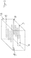
- FIG. 1 shows a heater assembly 1, in which a plurality of charcoal tablets 2 can be inserted.
- the plurality of charcoal tablets 2 is arranged on a grid 3, wherein the grid 3 defines a receiving volume 4.
- the grid 3 cuboid.
- the grid 3 has a different shape, such as cube-shaped, cylindrical or the like. It is essential that the grid 3 provides the largest possible contact surface for the plurality of charcoal tablets 2.
- the heating arrangement comprises a circulation fan 7, which is electrically connected to a controller 8.
- the controller 8 is connected to the at least one heating element 9.
- the controller 8 is configured to control both the circulation fan 7 and the at least one heating element 9.
- the heating arrangement 1 has in the housing volume 6 a receptacle 12 in which the at least one heating element 9 is accommodated.
- two meandering heating coils are provided which surround the receiving volume 4 of at least two sides.
- the at least two heating elements are arranged in such a way that they surround the grid 3 at least partially, preferably completely, along the cross-sectional surfaces of the grid 3.
- the heating elements 9 are according to FIG. 1 each formed in one piece. However, the heating elements may also be designed in several parts or the heating elements may have a different shape of the meandering course, such as spiral, straight, lattice-like or the like.
- the heating arrangement 1 furthermore has a collecting container 10 and / or optionally a further collecting container 11 for collecting the particles falling off the plurality of coal tablets, in particular ashes. By the collecting containers 11 and / or 10, the heating arrangement can be cleaned quickly and easily.
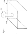
- FIG. 2 shows a receptacle 12 for receiving the at least one heating element 9.
- the receptacle 12 is disposed in the housing 5 of the heater assembly 1 and is thermally insulated from the housing volume 6.
- the outer wall of the receptacle 12 is preferably formed with a heat-resistant insulating layer, in particular coated.
- the controller 8 supplies the at least one heating element 9 with electrical energy, preferably with electricity.
- the receptacle 12 has a passage opening 16 for insertion of the grid 3.
- the receiving opening 16 is formed complementary to the cross-sectional area of the receiving volume 4, with which the grid 3 or its receiving volume 4 is inserted into the receptacle 12.
- the heating device 20 of the heating arrangement 1 comprises the controller 8, the circulation fan
- the heating arrangement 1 formed in two parts.
- the heating arrangement 1 comprises a base body 22, on which a cover 24 can be placed and removed again.
- the heating arrangement is formed with a one-piece housing 5.
- a catalytic converter 26 is mounted on the cover 24.
- the catalyst 26 is configured to receive particles from the plurality of charcoal tablets.
- the catalyst 26 has according to FIG. 3 a cylindrical mold 28, which serves as a conduit for the particle removal.
- the cover 24 is designed to be complementary to the base body 22, ie the cover 24 can be inserted into a guide (not shown) of the base body 22.
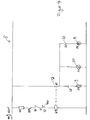
- FIG. 4 shows a circuit diagram of the controller 8, according to which the controller 8 on the one hand the fan 7 and on the other hand, the at least one heating element 9 can control.
- the controller 8 is designed to control the circulation fan 7 and the at least one heating element 9 in accordance with a predetermined course.
- the heater assembly 1 is further formed with at least one sensor 30, wherein the sensor 30 is preferably disposed in the receptacle 12.
- the sensor 30 detects the temperature of the at least one heating element 9 and / or the temperature in the receiving volume 4.
- the sensor 30 also has a heat-resistant protective layer.
- the at least one sensor 30 is, for example, an infrared sensor, a CCD module, or the like.
- the at least one sensor 30 is arranged outside the receptacle 12, preferably on an outer wall of the receptacle 12.
- the support surface of the sensor 30 on the receptacle 12 is preferably formed without insulation.
- the at least one sensor 30 forwards the detected signal, in particular the temperature signal, to the controller 8, wherein the controller 8 is configured to evaluate the signals of the sensor 30 and to use the circulating fan 7 and / or the sensor on the basis of the detected and / or evaluated signals to control at least one heating element 9.
- at least one predetermined setpoint value in particular setpoint temperature value, is stored.
- the setpoint is, for example, a minimum temperature that can be reached by the majority of charcoal tablets.
- the at least one predetermined desired value can also be a temperature of the receiving volume 4. If the at least one setpoint value is undershot, the controller 8 is designed to control the circulation fan 7 and / or the at least one heating element 9 so that the supply of air, ie oxygen, can be set, in particular increased, by the circulation fan 7. Further, the controller 8 is adapted to provide the at least one heating element 9 with energy, ie in particular to provide an increased power demand. Upon reaching the at least one predetermined setpoint value or when the at least one predetermined setpoint value is exceeded, the controller 8 is designed to reduce the energy supply of the at least one heating element 9 and optionally to reduce the supply of air via the circulation fan 7.
- a switch 32 Upon reaching the at least one target value, which means that the plurality of charcoal tablets are usable for subsequent use in a hookah, a switch 32 is switched, so that on the screen 18, an acoustic signal or an optical signal is displayed, which a user signals that the majority of charcoal tablets 2 to be heated have reached a minimum temperature, ie the predetermined desired value. If the setpoint temperature has not yet been reached, a time interval to be observed is displayed to the user on the display 18 until the plurality of charcoal tablets can be used for a subsequent use in a hookah. This is in the controller 8 stores a time-temperature curve, according to which a still waiting time interval can be estimated. The controller 8 is configured to determine the heating state of the plurality of introduced coal tablets 2. For this purpose, the controller 8 evaluates the signals transmitted by the at least one sensor 30.
- an operating light 34 to see which lights up when switching on the heater assembly 1 via the push button 19 to indicate that the heater assembly is functional.
- the circuit diagram of the circulating fan 7 is connected in series with a switch 36, while the at least one heating element 9 is connected in series with a switch 38. Furthermore, the at least one heating element 9 is connected to a thermostat switch 40.
- the controller 8 is designed to correspondingly switch the switches 36, 38, 40, 32 on the basis of a determined heating state of the number of charcoal tablets.
Landscapes
- Engineering & Computer Science (AREA)
- Food Science & Technology (AREA)
- Chemical & Material Sciences (AREA)
- Combustion & Propulsion (AREA)
- Mechanical Engineering (AREA)
- General Engineering & Computer Science (AREA)
- Catching Or Destruction (AREA)
- Thermotherapy And Cooling Therapy Devices (AREA)
- Devices And Processes Conducted In The Presence Of Fluids And Solid Particles (AREA)
Applications Claiming Priority (1)
| Application Number | Priority Date | Filing Date | Title |
|---|---|---|---|
| DE102016122558.4A DE102016122558B4 (de) | 2016-11-23 | 2016-11-23 | Heizungsanordnung |
Publications (2)
| Publication Number | Publication Date |
|---|---|
| EP3327353A1 true EP3327353A1 (fr) | 2018-05-30 |
| EP3327353B1 EP3327353B1 (fr) | 2021-06-02 |
Family
ID=60452413
Family Applications (1)
| Application Number | Title | Priority Date | Filing Date |
|---|---|---|---|
| EP17202837.5A Active EP3327353B1 (fr) | 2016-11-23 | 2017-11-21 | Dispositif de chauffage |
Country Status (2)
| Country | Link |
|---|---|
| EP (1) | EP3327353B1 (fr) |
| DE (1) | DE102016122558B4 (fr) |
Cited By (4)
| Publication number | Priority date | Publication date | Assignee | Title |
|---|---|---|---|---|
| EP3708010A1 (fr) * | 2019-03-13 | 2020-09-16 | InoxAir GmbH | Pipe à eau et unité de catalyseur pour pipe à eau |
| DE102019002965A1 (de) * | 2019-04-24 | 2020-10-29 | Shisha-Turbine GmbH | Anzündvorrichtung zum gleichzeitigen Anzünden und Durchglühen einer Mehrzahl an Shishakohlebriketts |
| RU226947U1 (ru) * | 2024-01-31 | 2024-06-28 | Сергей Станиславович Ширяев | Электрическая печь для розжига кальянных углей |
| DE202019006090U1 (de) | 2019-04-24 | 2024-10-07 | Turbine Group Gmbh | Anzündvorrichtung zum gleichzeitigen Anzünden und Durchglühen einer Mehrzahl an Shishakohlebriketts |
Families Citing this family (3)
| Publication number | Priority date | Publication date | Assignee | Title |
|---|---|---|---|---|
| US11825873B2 (en) * | 2020-03-09 | 2023-11-28 | Aspire North America Llc | Hookah |
| DE102020134852A1 (de) | 2020-12-23 | 2022-06-23 | Sevim Berber | Kohleanzünder und Verfahren zum Anzünden von Wasserpfeifenkohle |
| IL325965A (en) * | 2023-08-28 | 2026-03-01 | MHAHZRY Oriya | Electronic charcoal for hookah |
Citations (6)
| Publication number | Priority date | Publication date | Assignee | Title |
|---|---|---|---|---|
| FR2686400A1 (fr) * | 1992-01-17 | 1993-07-23 | Moulinex Sa | Support recevant une preparation alimentaire surgelee et monte dans une machine de decongelation et de rechauffage. |
| US20060081622A1 (en) * | 2003-12-18 | 2006-04-20 | Daewoo Electronics Corporation | Door structure of microwave oven usable as pizza oven |
| CN203454206U (zh) * | 2013-09-09 | 2014-02-26 | 侯清贵 | 一种新型炭炉 |
| DE102013001052A1 (de) * | 2013-01-22 | 2014-07-24 | Bernd Kupetz | Vorrichtung und Verfahren zum Anzünden und Durchglühen von festen Brennstoffen, insbesondere von schwer entzündbarer Naturkohle zum Rauchen von Wasserpfeifen (Shisha) |
| CN204143615U (zh) * | 2014-08-08 | 2015-02-04 | 刘水根 | 一种具有遥控功能的电子水烟炭 |
| DE202013012062U1 (de) * | 2012-07-31 | 2015-08-11 | Bishara Tannous | Zündeinrichtung |
Family Cites Families (2)
| Publication number | Priority date | Publication date | Assignee | Title |
|---|---|---|---|---|
| US8479746B1 (en) | 2006-05-09 | 2013-07-09 | Bishara Tannous | Water pipe starter and cleaning device |
| US20160348909A1 (en) * | 2015-06-01 | 2016-12-01 | Rayd Tissan | Hookah Electric Charcoal Burner |
-
2016
- 2016-11-23 DE DE102016122558.4A patent/DE102016122558B4/de active Active
-
2017
- 2017-11-21 EP EP17202837.5A patent/EP3327353B1/fr active Active
Patent Citations (6)
| Publication number | Priority date | Publication date | Assignee | Title |
|---|---|---|---|---|
| FR2686400A1 (fr) * | 1992-01-17 | 1993-07-23 | Moulinex Sa | Support recevant une preparation alimentaire surgelee et monte dans une machine de decongelation et de rechauffage. |
| US20060081622A1 (en) * | 2003-12-18 | 2006-04-20 | Daewoo Electronics Corporation | Door structure of microwave oven usable as pizza oven |
| DE202013012062U1 (de) * | 2012-07-31 | 2015-08-11 | Bishara Tannous | Zündeinrichtung |
| DE102013001052A1 (de) * | 2013-01-22 | 2014-07-24 | Bernd Kupetz | Vorrichtung und Verfahren zum Anzünden und Durchglühen von festen Brennstoffen, insbesondere von schwer entzündbarer Naturkohle zum Rauchen von Wasserpfeifen (Shisha) |
| CN203454206U (zh) * | 2013-09-09 | 2014-02-26 | 侯清贵 | 一种新型炭炉 |
| CN204143615U (zh) * | 2014-08-08 | 2015-02-04 | 刘水根 | 一种具有遥控功能的电子水烟炭 |
Cited By (6)
| Publication number | Priority date | Publication date | Assignee | Title |
|---|---|---|---|---|
| EP3708010A1 (fr) * | 2019-03-13 | 2020-09-16 | InoxAir GmbH | Pipe à eau et unité de catalyseur pour pipe à eau |
| WO2020182516A1 (fr) * | 2019-03-13 | 2020-09-17 | Inoxair Gmbh | Pipe à eau et unité catalyseuse pour un narguilé |
| US12329195B2 (en) | 2019-03-13 | 2025-06-17 | Inoxair Gmbh | Water pipe and catalyst unit for a water pipe |
| DE102019002965A1 (de) * | 2019-04-24 | 2020-10-29 | Shisha-Turbine GmbH | Anzündvorrichtung zum gleichzeitigen Anzünden und Durchglühen einer Mehrzahl an Shishakohlebriketts |
| DE202019006090U1 (de) | 2019-04-24 | 2024-10-07 | Turbine Group Gmbh | Anzündvorrichtung zum gleichzeitigen Anzünden und Durchglühen einer Mehrzahl an Shishakohlebriketts |
| RU226947U1 (ru) * | 2024-01-31 | 2024-06-28 | Сергей Станиславович Ширяев | Электрическая печь для розжига кальянных углей |
Also Published As
| Publication number | Publication date |
|---|---|
| DE102016122558B4 (de) | 2019-09-19 |
| DE102016122558A1 (de) | 2018-05-24 |
| EP3327353B1 (fr) | 2021-06-02 |
Similar Documents
| Publication | Publication Date | Title |
|---|---|---|
| EP3327353B1 (fr) | Dispositif de chauffage | |
| EP2444726B1 (fr) | Brûleur à gaz pour un champ de cuisson au gaz et champ de cuisson au gaz ainsi que procédé destiné au fonctionnement d'un tel champ de cuisson au gaz | |
| DE3532820A1 (de) | Vorrichtung zum gleichmaessigen erwaermen von raeumen | |
| DE102013001052A1 (de) | Vorrichtung und Verfahren zum Anzünden und Durchglühen von festen Brennstoffen, insbesondere von schwer entzündbarer Naturkohle zum Rauchen von Wasserpfeifen (Shisha) | |
| EP3163162B1 (fr) | Radiateur à infrarouge mobile | |
| EP2626639B1 (fr) | module de nettoyage UV pour une installation de nettoyage d'air pour cuisine à utilisation industrielle | |
| EP2444741A2 (fr) | Four de cuisson au gaz | |
| DE202015104184U1 (de) | Hochtemperatur-Grillgerät | |
| WO2009109317A2 (fr) | Module de brûleur à gaz pour plaque de cuisson à gaz, et plaque de cuisson à gaz correspondante | |
| EP2708128A2 (fr) | Dispositif de nettoyage pour un four et four | |
| DE3148162C2 (de) | Gasheizung | |
| DE102014013133A1 (de) | Vorrichtung und Verfahren zur Steuerung eines Betriebszustands beim Betrieb einer Dunstabzugshaube in einem Raum eines Gebäudes mit einer Feuerstätte | |
| DE10056080C1 (de) | Vorrichtung, insbesondere zum Entfachen von Grillfeuer | |
| DE10031167C2 (de) | Anordnung zum Garen von Speisen | |
| DE102008051060B4 (de) | Heizgerät mit Abgasüberwachungseinrichtung | |
| DE202018001770U1 (de) | Heizgerät | |
| EP2492595A1 (fr) | Dispositif d'allumage de charbon de bois doté d'un système de ventilation | |
| DE202019105279U1 (de) | Kombigrill | |
| DE202013010033U1 (de) | Gasgrill | |
| DE202018104036U1 (de) | Tragbare Heizvorrichtung für eine Wasserpfeife | |
| EP2664850B1 (fr) | Procédé de commande d'un dispositif de chauffage | |
| DE102014019284A1 (de) | Modularer Wärmetauscher, insbesondere für eine Holzvergaser-Kleinfeuerungsanlage, und System aus beiden | |
| DE102015121694A1 (de) | Luftreiniger mit Zusatzfunktion | |
| DE202019002225U1 (de) | Akkubetriebene elektrische Heizvorrichtung für Wasserpfeifen | |
| DE69118568T2 (de) | Horizontales Grillgerät |
Legal Events
| Date | Code | Title | Description |
|---|---|---|---|
| PUAI | Public reference made under article 153(3) epc to a published international application that has entered the european phase |
Free format text: ORIGINAL CODE: 0009012 |
|
| STAA | Information on the status of an ep patent application or granted ep patent |
Free format text: STATUS: THE APPLICATION HAS BEEN PUBLISHED |
|
| AK | Designated contracting states |
Kind code of ref document: A1 Designated state(s): AL AT BE BG CH CY CZ DE DK EE ES FI FR GB GR HR HU IE IS IT LI LT LU LV MC MK MT NL NO PL PT RO RS SE SI SK SM TR |
|
| AX | Request for extension of the european patent |
Extension state: BA ME |
|
| STAA | Information on the status of an ep patent application or granted ep patent |
Free format text: STATUS: REQUEST FOR EXAMINATION WAS MADE |
|
| 17P | Request for examination filed |
Effective date: 20180827 |
|
| RBV | Designated contracting states (corrected) |
Designated state(s): AL AT BE BG CH CY CZ DE DK EE ES FI FR GB GR HR HU IE IS IT LI LT LU LV MC MK MT NL NO PL PT RO RS SE SI SK SM TR |
|
| STAA | Information on the status of an ep patent application or granted ep patent |
Free format text: STATUS: EXAMINATION IS IN PROGRESS |
|
| 17Q | First examination report despatched |
Effective date: 20200113 |
|
| RIC1 | Information provided on ipc code assigned before grant |
Ipc: F23Q 7/04 20060101AFI20200103BHEP Ipc: A24F 1/30 20060101ALI20200103BHEP Ipc: A47J 37/07 20060101ALI20200103BHEP |
|
| GRAP | Despatch of communication of intention to grant a patent |
Free format text: ORIGINAL CODE: EPIDOSNIGR1 |
|
| STAA | Information on the status of an ep patent application or granted ep patent |
Free format text: STATUS: GRANT OF PATENT IS INTENDED |
|
| INTG | Intention to grant announced |
Effective date: 20210120 |
|
| GRAS | Grant fee paid |
Free format text: ORIGINAL CODE: EPIDOSNIGR3 |
|
| GRAA | (expected) grant |
Free format text: ORIGINAL CODE: 0009210 |
|
| STAA | Information on the status of an ep patent application or granted ep patent |
Free format text: STATUS: THE PATENT HAS BEEN GRANTED |
|
| REG | Reference to a national code |
Ref country code: CH Ref legal event code: EP |
|
| AK | Designated contracting states |
Kind code of ref document: B1 Designated state(s): AL AT BE BG CH CY CZ DE DK EE ES FI FR GB GR HR HU IE IS IT LI LT LU LV MC MK MT NL NO PL PT RO RS SE SI SK SM TR |
|
| REG | Reference to a national code |
Ref country code: GB Ref legal event code: FG4D Free format text: NOT ENGLISH |
|
| REG | Reference to a national code |
Ref country code: AT Ref legal event code: REF Ref document number: 1398797 Country of ref document: AT Kind code of ref document: T Effective date: 20210615 |
|
| REG | Reference to a national code |
Ref country code: IE Ref legal event code: FG4D Free format text: LANGUAGE OF EP DOCUMENT: GERMAN |
|
| REG | Reference to a national code |
Ref country code: DE Ref legal event code: R096 Ref document number: 502017010529 Country of ref document: DE |
|
| REG | Reference to a national code |
Ref country code: LT Ref legal event code: MG9D |
|
| PG25 | Lapsed in a contracting state [announced via postgrant information from national office to epo] |
Ref country code: FI Free format text: LAPSE BECAUSE OF FAILURE TO SUBMIT A TRANSLATION OF THE DESCRIPTION OR TO PAY THE FEE WITHIN THE PRESCRIBED TIME-LIMIT Effective date: 20210602 Ref country code: LT Free format text: LAPSE BECAUSE OF FAILURE TO SUBMIT A TRANSLATION OF THE DESCRIPTION OR TO PAY THE FEE WITHIN THE PRESCRIBED TIME-LIMIT Effective date: 20210602 Ref country code: HR Free format text: LAPSE BECAUSE OF FAILURE TO SUBMIT A TRANSLATION OF THE DESCRIPTION OR TO PAY THE FEE WITHIN THE PRESCRIBED TIME-LIMIT Effective date: 20210602 Ref country code: BG Free format text: LAPSE BECAUSE OF FAILURE TO SUBMIT A TRANSLATION OF THE DESCRIPTION OR TO PAY THE FEE WITHIN THE PRESCRIBED TIME-LIMIT Effective date: 20210902 |
|
| REG | Reference to a national code |
Ref country code: NL Ref legal event code: MP Effective date: 20210602 |
|
| PG25 | Lapsed in a contracting state [announced via postgrant information from national office to epo] |
Ref country code: GR Free format text: LAPSE BECAUSE OF FAILURE TO SUBMIT A TRANSLATION OF THE DESCRIPTION OR TO PAY THE FEE WITHIN THE PRESCRIBED TIME-LIMIT Effective date: 20210903 Ref country code: LV Free format text: LAPSE BECAUSE OF FAILURE TO SUBMIT A TRANSLATION OF THE DESCRIPTION OR TO PAY THE FEE WITHIN THE PRESCRIBED TIME-LIMIT Effective date: 20210602 Ref country code: PL Free format text: LAPSE BECAUSE OF FAILURE TO SUBMIT A TRANSLATION OF THE DESCRIPTION OR TO PAY THE FEE WITHIN THE PRESCRIBED TIME-LIMIT Effective date: 20210602 Ref country code: NO Free format text: LAPSE BECAUSE OF FAILURE TO SUBMIT A TRANSLATION OF THE DESCRIPTION OR TO PAY THE FEE WITHIN THE PRESCRIBED TIME-LIMIT Effective date: 20210902 Ref country code: RS Free format text: LAPSE BECAUSE OF FAILURE TO SUBMIT A TRANSLATION OF THE DESCRIPTION OR TO PAY THE FEE WITHIN THE PRESCRIBED TIME-LIMIT Effective date: 20210602 Ref country code: SE Free format text: LAPSE BECAUSE OF FAILURE TO SUBMIT A TRANSLATION OF THE DESCRIPTION OR TO PAY THE FEE WITHIN THE PRESCRIBED TIME-LIMIT Effective date: 20210602 |
|
| PG25 | Lapsed in a contracting state [announced via postgrant information from national office to epo] |
Ref country code: SK Free format text: LAPSE BECAUSE OF FAILURE TO SUBMIT A TRANSLATION OF THE DESCRIPTION OR TO PAY THE FEE WITHIN THE PRESCRIBED TIME-LIMIT Effective date: 20210602 Ref country code: SM Free format text: LAPSE BECAUSE OF FAILURE TO SUBMIT A TRANSLATION OF THE DESCRIPTION OR TO PAY THE FEE WITHIN THE PRESCRIBED TIME-LIMIT Effective date: 20210602 Ref country code: CZ Free format text: LAPSE BECAUSE OF FAILURE TO SUBMIT A TRANSLATION OF THE DESCRIPTION OR TO PAY THE FEE WITHIN THE PRESCRIBED TIME-LIMIT Effective date: 20210602 Ref country code: EE Free format text: LAPSE BECAUSE OF FAILURE TO SUBMIT A TRANSLATION OF THE DESCRIPTION OR TO PAY THE FEE WITHIN THE PRESCRIBED TIME-LIMIT Effective date: 20210602 Ref country code: PT Free format text: LAPSE BECAUSE OF FAILURE TO SUBMIT A TRANSLATION OF THE DESCRIPTION OR TO PAY THE FEE WITHIN THE PRESCRIBED TIME-LIMIT Effective date: 20211004 Ref country code: NL Free format text: LAPSE BECAUSE OF FAILURE TO SUBMIT A TRANSLATION OF THE DESCRIPTION OR TO PAY THE FEE WITHIN THE PRESCRIBED TIME-LIMIT Effective date: 20210602 Ref country code: RO Free format text: LAPSE BECAUSE OF FAILURE TO SUBMIT A TRANSLATION OF THE DESCRIPTION OR TO PAY THE FEE WITHIN THE PRESCRIBED TIME-LIMIT Effective date: 20210602 Ref country code: ES Free format text: LAPSE BECAUSE OF FAILURE TO SUBMIT A TRANSLATION OF THE DESCRIPTION OR TO PAY THE FEE WITHIN THE PRESCRIBED TIME-LIMIT Effective date: 20210602 |
|
| REG | Reference to a national code |
Ref country code: DE Ref legal event code: R097 Ref document number: 502017010529 Country of ref document: DE |
|
| PLBE | No opposition filed within time limit |
Free format text: ORIGINAL CODE: 0009261 |
|
| STAA | Information on the status of an ep patent application or granted ep patent |
Free format text: STATUS: NO OPPOSITION FILED WITHIN TIME LIMIT |
|
| PG25 | Lapsed in a contracting state [announced via postgrant information from national office to epo] |
Ref country code: DK Free format text: LAPSE BECAUSE OF FAILURE TO SUBMIT A TRANSLATION OF THE DESCRIPTION OR TO PAY THE FEE WITHIN THE PRESCRIBED TIME-LIMIT Effective date: 20210602 |
|
| 26N | No opposition filed |
Effective date: 20220303 |
|
| PG25 | Lapsed in a contracting state [announced via postgrant information from national office to epo] |
Ref country code: AL Free format text: LAPSE BECAUSE OF FAILURE TO SUBMIT A TRANSLATION OF THE DESCRIPTION OR TO PAY THE FEE WITHIN THE PRESCRIBED TIME-LIMIT Effective date: 20210602 |
|
| PG25 | Lapsed in a contracting state [announced via postgrant information from national office to epo] |
Ref country code: MC Free format text: LAPSE BECAUSE OF FAILURE TO SUBMIT A TRANSLATION OF THE DESCRIPTION OR TO PAY THE FEE WITHIN THE PRESCRIBED TIME-LIMIT Effective date: 20210602 |
|
| REG | Reference to a national code |
Ref country code: CH Ref legal event code: PL |
|
| PG25 | Lapsed in a contracting state [announced via postgrant information from national office to epo] |
Ref country code: LU Free format text: LAPSE BECAUSE OF NON-PAYMENT OF DUE FEES Effective date: 20211121 Ref country code: IT Free format text: LAPSE BECAUSE OF FAILURE TO SUBMIT A TRANSLATION OF THE DESCRIPTION OR TO PAY THE FEE WITHIN THE PRESCRIBED TIME-LIMIT Effective date: 20210602 Ref country code: BE Free format text: LAPSE BECAUSE OF NON-PAYMENT OF DUE FEES Effective date: 20211130 |
|
| REG | Reference to a national code |
Ref country code: BE Ref legal event code: MM Effective date: 20211130 |
|
| PG25 | Lapsed in a contracting state [announced via postgrant information from national office to epo] |
Ref country code: IE Free format text: LAPSE BECAUSE OF NON-PAYMENT OF DUE FEES Effective date: 20211121 |
|
| PG25 | Lapsed in a contracting state [announced via postgrant information from national office to epo] |
Ref country code: HU Free format text: LAPSE BECAUSE OF FAILURE TO SUBMIT A TRANSLATION OF THE DESCRIPTION OR TO PAY THE FEE WITHIN THE PRESCRIBED TIME-LIMIT; INVALID AB INITIO Effective date: 20171121 |
|
| P01 | Opt-out of the competence of the unified patent court (upc) registered |
Effective date: 20230424 |
|
| PG25 | Lapsed in a contracting state [announced via postgrant information from national office to epo] |
Ref country code: CY Free format text: LAPSE BECAUSE OF FAILURE TO SUBMIT A TRANSLATION OF THE DESCRIPTION OR TO PAY THE FEE WITHIN THE PRESCRIBED TIME-LIMIT Effective date: 20210602 |
|
| PG25 | Lapsed in a contracting state [announced via postgrant information from national office to epo] |
Ref country code: LI Free format text: LAPSE BECAUSE OF NON-PAYMENT OF DUE FEES Effective date: 20220701 Ref country code: CH Free format text: LAPSE BECAUSE OF NON-PAYMENT OF DUE FEES Effective date: 20220701 |
|
| PG25 | Lapsed in a contracting state [announced via postgrant information from national office to epo] |
Ref country code: MK Free format text: LAPSE BECAUSE OF FAILURE TO SUBMIT A TRANSLATION OF THE DESCRIPTION OR TO PAY THE FEE WITHIN THE PRESCRIBED TIME-LIMIT Effective date: 20210602 |
|
| PG25 | Lapsed in a contracting state [announced via postgrant information from national office to epo] |
Ref country code: TR Free format text: LAPSE BECAUSE OF FAILURE TO SUBMIT A TRANSLATION OF THE DESCRIPTION OR TO PAY THE FEE WITHIN THE PRESCRIBED TIME-LIMIT Effective date: 20210602 |
|
| PG25 | Lapsed in a contracting state [announced via postgrant information from national office to epo] |
Ref country code: MT Free format text: LAPSE BECAUSE OF FAILURE TO SUBMIT A TRANSLATION OF THE DESCRIPTION OR TO PAY THE FEE WITHIN THE PRESCRIBED TIME-LIMIT Effective date: 20210602 |
|
| PGFP | Annual fee paid to national office [announced via postgrant information from national office to epo] |
Ref country code: DE Payment date: 20241011 Year of fee payment: 8 |
|
| PGFP | Annual fee paid to national office [announced via postgrant information from national office to epo] |
Ref country code: GB Payment date: 20241121 Year of fee payment: 8 |
|
| PGFP | Annual fee paid to national office [announced via postgrant information from national office to epo] |
Ref country code: FR Payment date: 20241121 Year of fee payment: 8 |
|
| PGFP | Annual fee paid to national office [announced via postgrant information from national office to epo] |
Ref country code: AT Payment date: 20241118 Year of fee payment: 8 |