EP3327437A2 - Procédé et dispositif de détermination de particules solides dans un flux liquide - Google Patents
Procédé et dispositif de détermination de particules solides dans un flux liquide Download PDFInfo
- Publication number
- EP3327437A2 EP3327437A2 EP17198233.3A EP17198233A EP3327437A2 EP 3327437 A2 EP3327437 A2 EP 3327437A2 EP 17198233 A EP17198233 A EP 17198233A EP 3327437 A2 EP3327437 A2 EP 3327437A2
- Authority
- EP
- European Patent Office
- Prior art keywords
- content
- gas
- particles
- liquid stream
- solid particles
- Prior art date
- Legal status (The legal status is an assumption and is not a legal conclusion. Google has not performed a legal analysis and makes no representation as to the accuracy of the status listed.)
- Withdrawn
Links
- 239000002245 particle Substances 0.000 title claims abstract description 217
- 239000007788 liquid Substances 0.000 title claims abstract description 109
- 239000007787 solid Substances 0.000 title claims abstract description 60
- 238000000034 method Methods 0.000 title claims abstract description 27
- 230000002452 interceptive effect Effects 0.000 claims description 24
- 238000007906 compression Methods 0.000 claims description 16
- 230000006835 compression Effects 0.000 claims description 15
- 238000007872 degassing Methods 0.000 claims description 11
- 230000003287 optical effect Effects 0.000 claims description 10
- 238000011156 evaluation Methods 0.000 claims description 7
- 238000010521 absorption reaction Methods 0.000 claims description 3
- 239000012530 fluid Substances 0.000 claims description 3
- 230000008033 biological extinction Effects 0.000 claims 1
- 239000007789 gas Substances 0.000 description 83
- 238000005259 measurement Methods 0.000 description 11
- 238000000605 extraction Methods 0.000 description 4
- 230000005540 biological transmission Effects 0.000 description 3
- 239000010687 lubricating oil Substances 0.000 description 3
- 230000001914 calming effect Effects 0.000 description 2
- 238000002485 combustion reaction Methods 0.000 description 2
- 238000010276 construction Methods 0.000 description 2
- 230000001419 dependent effect Effects 0.000 description 2
- 238000012544 monitoring process Methods 0.000 description 2
- 238000002360 preparation method Methods 0.000 description 2
- 241000908523 Phnom Penh bat virus Species 0.000 description 1
- 230000002411 adverse Effects 0.000 description 1
- 238000013459 approach Methods 0.000 description 1
- 238000007796 conventional method Methods 0.000 description 1
- 238000004090 dissolution Methods 0.000 description 1
- 239000012535 impurity Substances 0.000 description 1
- 238000002955 isolation Methods 0.000 description 1
- 230000031700 light absorption Effects 0.000 description 1
- 238000012423 maintenance Methods 0.000 description 1
- 231100000344 non-irritating Toxicity 0.000 description 1
- 239000003921 oil Substances 0.000 description 1
- 230000001624 sedative effect Effects 0.000 description 1
- 230000001960 triggered effect Effects 0.000 description 1
- 238000011144 upstream manufacturing Methods 0.000 description 1
Images
Classifications
-
- G—PHYSICS
- G01—MEASURING; TESTING
- G01N—INVESTIGATING OR ANALYSING MATERIALS BY DETERMINING THEIR CHEMICAL OR PHYSICAL PROPERTIES
- G01N33/00—Investigating or analysing materials by specific methods not covered by groups G01N1/00 - G01N31/00
- G01N33/26—Oils; Viscous liquids; Paints; Inks
- G01N33/28—Oils, i.e. hydrocarbon liquids
- G01N33/2888—Lubricating oil characteristics, e.g. deterioration
-
- G—PHYSICS
- G01—MEASURING; TESTING
- G01N—INVESTIGATING OR ANALYSING MATERIALS BY DETERMINING THEIR CHEMICAL OR PHYSICAL PROPERTIES
- G01N15/00—Investigating characteristics of particles; Investigating permeability, pore-volume or surface-area of porous materials
- G01N15/02—Investigating particle size or size distribution
- G01N15/0205—Investigating particle size or size distribution by optical means
-
- G—PHYSICS
- G01—MEASURING; TESTING
- G01N—INVESTIGATING OR ANALYSING MATERIALS BY DETERMINING THEIR CHEMICAL OR PHYSICAL PROPERTIES
- G01N15/00—Investigating characteristics of particles; Investigating permeability, pore-volume or surface-area of porous materials
- G01N2015/0042—Investigating dispersion of solids
- G01N2015/0053—Investigating dispersion of solids in liquids, e.g. trouble
-
- G—PHYSICS
- G01—MEASURING; TESTING
- G01N—INVESTIGATING OR ANALYSING MATERIALS BY DETERMINING THEIR CHEMICAL OR PHYSICAL PROPERTIES
- G01N33/00—Investigating or analysing materials by specific methods not covered by groups G01N1/00 - G01N31/00
- G01N33/26—Oils; Viscous liquids; Paints; Inks
- G01N33/28—Oils, i.e. hydrocarbon liquids
- G01N33/2835—Specific substances contained in the oils or fuels
- G01N33/2841—Gas in oils, e.g. hydrogen in insulating oils
Definitions
- the present invention relates to a method and a device for determining a content of interfering solid particles in a liquid flow, preferably in a hydraulic system.
- the invention also relates to a machine equipped with such a device.
- a variety of machines work with one or more hydraulic systems, in particular hydraulic circuits. Of particular importance are lubricating oil travel. This may in principle be mobile machines such. Ex. Drive units, especially gearbox, crankshaft, camshafts, in vehicles, and stationary machines act such. Eg transmission of wind turbines or conveyors.
- the content of solid particles in the liquid flow of such a hydraulic system correlates with wear or with an operating state of the associated machine. Accordingly, it is of crucial importance for the function monitoring or for the maintenance of such a machine to be able to determine the content of solid particles as accurately as possible.
- gas particles are regularly included, which can not be distinguished from solid particles by conventional sensors, so that a conventional method often measures too high a content of particles in the liquid flow.
- the known device comprises a measuring path, which has a particle sensor for detecting the particle entry, and is characterized by a Sample preparation route, which can be connected to the measuring path in a fluid-conducting manner by means of a connection device.
- This sample preparation path has at least one additional device, with the aid of which further fluid-foreign impurities, in particular gas particles, can be detected and / or at least partially eliminated from the liquid flow.
- the known device thus uses an additional sensor for determining the gas particles. This can be associated with increased costs.
- This device thus assumes that all gas particles can be removed from the liquid stream upstream of the sensor for determining the solid particles. For this purpose, a comparatively large amount of equipment is required. In addition, it can not be ruled out that a certain proportion of gas particles still remains in the liquid stream and is therefore counted by the sensor.
- the present invention is concerned with the problem of providing an improved embodiment for a method or a device of the type described above, which is characterized in particular by a low-cost feasibility.
- the present invention is based on the general idea to measure the particle content of solid particles and gas particles in the liquid flow and then to check this measurement in terms of their plausibility.
- this first aspect of the invention proposes to additionally determine the gas content in the liquid stream.
- the reliability of the determined particle content in the liquid stream can be assessed. The lower the gas content in the liquid stream, the more reliable the determined particle content in the liquid stream.
- it may optionally be provided to compress the liquid flow in order, on the one hand, to further assist in dissolving the gases in the liquid and, on the other hand, to reduce the size of the gas particles.
- This measure is based on the knowledge that at the same Number of gas particles smaller gas particles less adversely affect the measurement of particulate content than larger gas particles.
- a gas content limit is defined or predetermined, which can be used to check the plausibility. If the determined gas content is below this gas content limit value, the determined particle content has sufficient reliability. If, on the other hand, the determined gas content exceeds the specified gas content limit value, the determined particle content is too unreliable in order to provide an accurate conclusion about the condition of the liquid or of the hydraulic system or the associated machine.
- the gas content in the liquid flow can be determined with the aid of an optical sensor which performs a scattered light measurement. This is based on the knowledge that gas particles have a different scattered light characteristic than solid particles.
- the total particle content that is, regardless of whether it is gas particles or solid particles, can be determined in a conventional manner.
- an optical sensor can also be used here, which determines the proportion of absorbed light or performs an extraction method.
- the invention is based on the general idea, in addition to the number of particles, of measuring the size of the particles as well. Furthermore, it is essential that the determination of the particle size takes place in a compressed state.
- the invention uses the knowledge that the liquid flow and the solid particles are incompressible, while the gas particles are compressible. As a result, only the gas particles are reduced in size by the compression. Furthermore, it was recognized according to this second aspect that not all solid particles are critical for the respective machine, but only from a predetermined particle size limit.
- the disturbing solid particles are characterized in that their particle size is greater than the aforementioned particle size limit.
- the compressed gas particles are not identified as interfering particles, whether they are solid or gaseous.
- only the content of interfering particles is determined in the method according to the invention or in the associated apparatus, whereby it is achieved by compression of the gas particles that gas particles contained in the liquid stream are smaller than a predetermined particle size limit. Only particles whose particle size is above this particle size limit are identified as interfering. All other particles, regardless of whether they are solid particles or gas particles, are classified as non-irritating.
- the method according to the invention and the associated device thus do without a highly complex sensor system.
- the content of interfering solid particles can be determined with relatively high reliability.
- the required expenditure on equipment is comparatively low.
- gas particles in the liquid stream Prior to compressing the gas particles in the liquid stream, further reducing the content of gas particles in the liquid stream may be performed.
- reducing the content of Gas particles in the liquid flow are mainly gas particles with larger particle size removed from the liquid stream. This can be done by degassing. Likewise, this can be done by dissolving the gas particles in the liquid stream. By this dissolution process, at least the size of the gas particles is reduced.
- a degassing device is used to reduce the content of gas particles in the liquid flow.
- This can optionally be combined with a calming section in order to further reduce the particle size of the gas particles by dissolving the gas in the liquid.
- the compression of the gas particles takes place in the liquid flow downstream of the degassing device. This simplifies the construction of the degassing device.
- the compression of the gas particles in the liquid stream by an increase in pressure in the liquid flow can take place.
- a pressure increase can be realized by a pump or the like.
- this pump is arranged in the liquid flow downstream of the degassing device.
- the determination of the content of the interfering solid particles in the liquid stream can, according to a preferred embodiment, be carried out by counting only the number of solid particles identified as interfering. The measured particles are then identified as interfering solid particles if the associated particle size is greater than the predetermined particle size limit. If, however, the associated particle size is smaller than the particle size limit, the respective particle is not disturbing or as Gas particles identified. If only the identified as disturbing solid particles are counted, the required equipment cost is relatively low.
- the content of interfering solid particles in the liquid stream can also be determined by first counting the total number of all solid particles and gas particles in the liquid stream and then subtracting from this total number the number of particles which are identified as not disturbing. In other words, all gas particles and solid particles whose particle size is smaller than the particle size limit are withdrawn.
- the count of the particles and the size determination of the particles can basically fall apart, which can lead to a simplification in the construction of an associated device.
- the number of particles can be determined by means of an optical sensor.
- the particle size can be conveniently determined by means of an optical sensor.
- the particle size and the number of particles can be determined with the same sensor, which preferably operates optically. It is also conceivable to provide a sensor which counts the particles regardless of their size, and to provide a further sensor which either only counts the particles whose particle size is above the particle size limit, or only counts those particles whose particle size is below the particle size limit.
- a device comprises a reduction device for reducing a gas content of gas particles in the liquid flow, a compression device arranged downstream of the reduction device for compressing the gas particles in the liquid flow, a measuring device arranged downstream of the compression device and a Evaluation device which is coupled to the measuring device and which is designed or programmed so that it can perform the method described above during operation of the device.
- a machine according to the invention has at least one hydraulic system and is equipped with at least one device of the type described above.
- a machine 1 comprises a hydraulic system 2 for supplying a component 3 of the machine 1 with a liquid 4.
- the machine 1 is a motor vehicle or an internal combustion engine.
- the component 3 may, for example, be a transmission.
- the liquid 4 is then expediently a transmission oil.
- a crank mechanism of the internal combustion engine can form such a component 3, which is supplied with lubricating oil, or a valve train with at least one camshaft, which is supplied with lubricating oil.
- the hydraulic system 2 comprises a tank 5 or a reservoir 5 for the liquid 4. From the reservoir 5, a feed line 6 leads to the respective component 3. A return line 7 leads from the respective component 3 back to the reservoir 5.
- the machine 1 is also equipped with a device 8 for detecting a content of interfering solid particles in a liquid flow.
- the device 8 measures the content of solid particles in a liquid flow from the liquid 4 and then provides a control of the machine 1, not shown here, a value which correlates with the actual content of solid particles in the liquid.
- this content is given in the liquid in PPM per unit volume, for example PPMV, PPBV or PPTV.
- VPM is possible.
- a ground reference is also conceivable, for example PPMW, PPBW or PPTW.
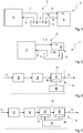
- Fig. 1 can this device 8, the liquid flow via a supply line 9 from the reservoir 5 are supplied. The return of the liquid flow from the device 8 to the reservoir 5 can then take place via a return line 10.
- Fig. 1 Thus shows a parallel connection of the component 3 on the one hand and the device 8 on the other hand in the hydraulic system 2.
- Fig. 2 a series connection of component 3 on the one hand and device 8 on the other hand in the hydraulic system 2.
- the device 8 is purely exemplary incorporated in the return line 7.
- the return line 7 is subdivided into a feed section 9 'leading from the component 3 to the device 8 and a return section 10' leading from the device 8 to the reservoir 5.
- the device 8 has an inlet 11 for the liquid flow and an outlet 12 for the liquid flow.
- the inlet 11 for the liquid flow
- the supply line 9 while at the outlet 12, the return line 10 is connected.
- the return line 10 is connected.
- the example of Fig. 2 is connected to the inlet 11 of the feed section 9 'of the return line 7. At the outlet 12 of the return section 10 'of the return line 7 is connected.
- the device 8 comprises a reduction device 13 for reducing a content of gas particles in the liquid flow. Furthermore, the device 8 comprises a compression device 14 for compressing the gas particles in Liquid flow. In this case, the compression device 14 is arranged downstream of the reduction device 13.
- the device 8 is equipped with a measuring device 15, with the help of which in general the content of solid particles in the liquid stream can be measured.
- the measuring device 15 according to a first aspect of the invention can determine the particle content and carry out a plausibility check for the measured value.
- the measuring device 15 according to a second aspect of the invention can measure the particle number and the particle size of the solid particles and the compressed gas particles in the liquid flow.
- an evaluation device 16 is provided, which is coupled to the measuring device 15. This evaluation device 16 is configured so that it can carry out the method explained in more detail below.
- the measuring device 15 includes in the example of Fig. 3 in a single measuring station 17, an optical sensor 18, which according to the first aspect can determine both the particle content in the liquid stream and the gas content in the liquid stream. According to the second aspect, this sensor 18 can determine both the number of particles and the particle size in the liquid flow.
- FIG. 4 shows Fig. 4 an embodiment in which the measuring device 15 according to the first aspect, two separate measuring stations 19, 20, in each of which an optical sensor 21 and 22 is arranged.
- One of the sensors 21, 22 may be designed to measure the particle content in the liquid stream.
- the other sensor 21, 22 may be designed to measure the proportion of gas in the liquid stream.
- two separate measuring points 19, 20 can here also a common measuring point as in the example of Fig. 3 be provided, except that in it also two separate sensors 21, 22 are used.
- the reduction device 13 may include a degassing device and / or a calming section. While the degassing device separates gas particles from the liquid flow, a release of the gas of the gas particles in the liquid of the liquid flow takes place in the settling section. This reduces the particle size of the gas particles. Subsequently, the gas particles are compressed in the liquid stream. This takes place in the compression device 14.
- the compression device 14 may have a pump for this purpose or be formed by a pump.
- a determination of the particle content in the liquid stream then takes place in the measuring device 15.
- Both solid particles and gas particles are detected in the liquid stream.
- a simple, conventional sensor can be used, which is designed, for example, as a turbidity sensor and detects only the transmitted light and compares it with the emitted light. It is clear that this comparison of emitted light and incoming light for determining the particle content can ultimately also be carried out in the evaluation device 16.
- a determination of the gas content in the liquid stream in particular in the measuring device 15, a determination of the gas content in the liquid stream. With the aid of an optical sensor 18 or 21 or 22, for example, a scattered light measurement can be performed to determine the gas content in the Determine fluid flow.
- the scattered light characteristic of gas particles in the liquid stream differs significantly from the scattered light characteristic of solid particles in the liquid stream.
- the gas content in the liquid flow can be determined.
- the particle content in the liquid flow can be determined with the respective optical sensor 18 or 21 or 22, in particular by means of extraction methods or by means of light absorption, the measurement by means of extraction or absorption being independent of whether the particles are solid or gaseous.
- solids particles and gas particles are detected together with the extraction process or absorption process, so that the total particle content of solid and gaseous particles in the liquid flow is determined.
- a plausibility check is preferably carried out with the aid of the evaluation device 16.
- the plausibility of the determined particle content is estimated or evaluated on the basis of the gas content. If the determined gas content is below a predetermined gas content limit, the determined particle content is considered to be plausible. If, on the other hand, the determined gas content exceeds the predetermined gas content limit value, the determined particle content is assessed as not plausible or unreliable. As a result, measures to reduce the gas content can be initiated. Likewise, a new measurement can be triggered.
- an identification of the solid particles and the gas particles can be carried out on the basis of their particle size. More specifically, the particle size becomes troublesome Solid particles of non-interfering solid particles and per se non-interfering gas particles distinguished. Interfering solid particles are present when the particles have a particle size that is greater than a predetermined particle size limit. On the other hand, if the particle size is smaller than the predetermined particle size limit, it is either non-disruptive solid particles or gas particles which likewise do not disturb. Taking into account the disturbing solid particles thus determined, it is now possible to determine the content of the disturbing solid particles in the liquid stream.
Landscapes
- Chemical & Material Sciences (AREA)
- Health & Medical Sciences (AREA)
- Life Sciences & Earth Sciences (AREA)
- General Physics & Mathematics (AREA)
- Pathology (AREA)
- Analytical Chemistry (AREA)
- Biochemistry (AREA)
- General Health & Medical Sciences (AREA)
- Engineering & Computer Science (AREA)
- Immunology (AREA)
- Physics & Mathematics (AREA)
- Dispersion Chemistry (AREA)
- Chemical Kinetics & Catalysis (AREA)
- General Chemical & Material Sciences (AREA)
- Oil, Petroleum & Natural Gas (AREA)
- Food Science & Technology (AREA)
- Medicinal Chemistry (AREA)
- Investigating Or Analysing Materials By Optical Means (AREA)
- Measuring Volume Flow (AREA)
Applications Claiming Priority (1)
| Application Number | Priority Date | Filing Date | Title |
|---|---|---|---|
| DE102016223221.5A DE102016223221A1 (de) | 2016-11-23 | 2016-11-23 | Verfahren und Vorrichtung zum Ermitteln von Feststoffpartikeln in einem Flüssigkeitsstrom |
Publications (2)
| Publication Number | Publication Date |
|---|---|
| EP3327437A2 true EP3327437A2 (fr) | 2018-05-30 |
| EP3327437A3 EP3327437A3 (fr) | 2018-07-11 |
Family
ID=60186072
Family Applications (1)
| Application Number | Title | Priority Date | Filing Date |
|---|---|---|---|
| EP17198233.3A Withdrawn EP3327437A3 (fr) | 2016-11-23 | 2017-10-25 | Procédé et dispositif de détermination de particules solides dans un flux liquide |
Country Status (2)
| Country | Link |
|---|---|
| EP (1) | EP3327437A3 (fr) |
| DE (1) | DE102016223221A1 (fr) |
Family Cites Families (6)
| Publication number | Priority date | Publication date | Assignee | Title |
|---|---|---|---|---|
| US4164137A (en) * | 1978-06-02 | 1979-08-14 | Clark Equipment Company | Method of measuring volume of air entrained in hydraulic fluids |
| DE8912584U1 (de) * | 1989-10-24 | 1989-12-07 | Hydac Technology GmbH, 6603 Sulzbach | Partikelzähler |
| DE10343457C5 (de) * | 2003-09-19 | 2012-01-12 | Hydac Filtertechnik Gmbh | Vorrichtung zur Partikelmessung |
| DE202009017886U1 (de) | 2009-10-05 | 2010-08-26 | Robert Bosch Gmbh | Vorrichtung zur Partikelmessung in stark mit Gas, insbesondere Luft beladenem Medium |
| DE102012013255A1 (de) | 2012-07-03 | 2014-05-08 | Hydac Filter Systems Gmbh | Verfahren zum Detektieren von Partikeln in einem Fluidstrom |
| DE102012016458A1 (de) | 2012-08-17 | 2014-05-15 | Hydac Filter Systems Gmbh | Vorrichtung zum Feststellen von Partikelverschmutzungen in Fluiden |
-
2016
- 2016-11-23 DE DE102016223221.5A patent/DE102016223221A1/de not_active Withdrawn
-
2017
- 2017-10-25 EP EP17198233.3A patent/EP3327437A3/fr not_active Withdrawn
Also Published As
| Publication number | Publication date |
|---|---|
| DE102016223221A1 (de) | 2018-05-24 |
| EP3327437A3 (fr) | 2018-07-11 |
Similar Documents
| Publication | Publication Date | Title |
|---|---|---|
| DE2509411C2 (de) | Vorrichtung zum Analysieren des Emissions-Gehalts der Abgase eines Verbrennungsmotors | |
| DE3128072A1 (de) | Pruefstand zum pruefen von einspritzduesen | |
| DE102016105016B4 (de) | Verfahren zur Erkennung eines Ausfalls eines Sensors einer Fahrzeugsicherheitseinrichtung | |
| DE112017001547T5 (de) | Verfahren zum Diagnostizieren des Zustandes einer Rollführungsvorrichtung | |
| DE3034556A1 (de) | Pruefvorrichtung fuer einspritzpumpen von brennkraftmaschinen | |
| EP0881501B1 (fr) | Dispositif d'essai de fonctionnement d'un système de réglage à commande électronique dans un véhicule automobile après un processus de production | |
| DE202009017886U1 (de) | Vorrichtung zur Partikelmessung in stark mit Gas, insbesondere Luft beladenem Medium | |
| DE102008002356A1 (de) | Kraftfahrzeug oder Arbeitsmaschine sowie Überwachungsverfahren | |
| DE102011116730A1 (de) | Verfahren und System zur Bedatung eines Steuergeräts | |
| DE102011057188B4 (de) | Verfahren und System zum Messen einer Motorölverschlechterung | |
| EP1923694B1 (fr) | Methode et dispositif pour déterminer la quantité d'huile dans un flux de gaz | |
| EP0962750A1 (fr) | Procédé pour déterminer la consommation de carburant et la condition de fonctionnement d'un moteur de combustion interne | |
| EP3327437A2 (fr) | Procédé et dispositif de détermination de particules solides dans un flux liquide | |
| EP2885620B1 (fr) | Dispositif de détermination de contaminants particulaires dans des fluides | |
| DE102014206252A1 (de) | Verfahren und Einrichtung zum Diagnostizieren der Funktionsfähigkeit eines Dieselpartikelfilters | |
| DE19727669A1 (de) | Verfahren zur Überwachung der Funktion einer Saugrohrklappe zur Saugrohrumschaltung einer Brennkraftmaschine | |
| DE102007007631A1 (de) | Vorrichtung und Verfahren zur Anzeige einer Motordrehzahl in einem Kraftfahrzeug | |
| DE10302054B4 (de) | Verfahren zum Betreiben einer Brennkraftmaschine | |
| EP1955062B1 (fr) | Dispositif de determination de la filtrabilite de fluides et en particulier d'huiles de transmission | |
| DE102021204924A1 (de) | Verfahren zur externen Detektion von Anomalien bei Kraftfahrzeugen | |
| DE202009007593U1 (de) | System zur Pflege und/oder Qualitätsüberwachung | |
| DE19852226B4 (de) | Verfahren und Vorrichtung zur Ermittlung einer nachzufüllenden Schmiermittelmenge | |
| DE4427084A1 (de) | Fahrzeugsicherungsanordnung | |
| EP0100831B1 (fr) | Dispositif pour la mesure de la consommation de combustible des véhicules sur un banc d'épreuve à rouleaux | |
| EP0501242A1 (fr) | Procédé de détermination du débit de gaz d'échappement |
Legal Events
| Date | Code | Title | Description |
|---|---|---|---|
| PUAI | Public reference made under article 153(3) epc to a published international application that has entered the european phase |
Free format text: ORIGINAL CODE: 0009012 |
|
| AK | Designated contracting states |
Kind code of ref document: A2 Designated state(s): AL AT BE BG CH CY CZ DE DK EE ES FI FR GB GR HR HU IE IS IT LI LT LU LV MC MK MT NL NO PL PT RO RS SE SI SK SM TR |
|
| AX | Request for extension of the european patent |
Extension state: BA ME |
|
| PUAL | Search report despatched |
Free format text: ORIGINAL CODE: 0009013 |
|
| AK | Designated contracting states |
Kind code of ref document: A3 Designated state(s): AL AT BE BG CH CY CZ DE DK EE ES FI FR GB GR HR HU IE IS IT LI LT LU LV MC MK MT NL NO PL PT RO RS SE SI SK SM TR |
|
| AX | Request for extension of the european patent |
Extension state: BA ME |
|
| RIC1 | Information provided on ipc code assigned before grant |
Ipc: G01N 33/28 20060101AFI20180606BHEP Ipc: G01N 15/14 20060101ALI20180606BHEP |
|
| RIC1 | Information provided on ipc code assigned before grant |
Ipc: G01N 33/28 20060101AFI20180613BHEP Ipc: G01N 15/14 20060101ALI20180613BHEP |
|
| STAA | Information on the status of an ep patent application or granted ep patent |
Free format text: STATUS: THE APPLICATION IS DEEMED TO BE WITHDRAWN |
|
| 18D | Application deemed to be withdrawn |
Effective date: 20190112 |