EP3327481B1 - Procédé de modélisation d'un dispositif d'imagerie, produit de programme informatique correspondant et support lisible par ordinateur - Google Patents
Procédé de modélisation d'un dispositif d'imagerie, produit de programme informatique correspondant et support lisible par ordinateur Download PDFInfo
- Publication number
- EP3327481B1 EP3327481B1 EP16306565.9A EP16306565A EP3327481B1 EP 3327481 B1 EP3327481 B1 EP 3327481B1 EP 16306565 A EP16306565 A EP 16306565A EP 3327481 B1 EP3327481 B1 EP 3327481B1
- Authority
- EP
- European Patent Office
- Prior art keywords
- distance
- optical system
- imaging device
- image
- plane
- Prior art date
- Legal status (The legal status is an assumption and is not a legal conclusion. Google has not performed a legal analysis and makes no representation as to the accuracy of the status listed.)
- Active
Links
Images


Classifications
-
- G—PHYSICS
- G06—COMPUTING OR CALCULATING; COUNTING
- G06T—IMAGE DATA PROCESSING OR GENERATION, IN GENERAL
- G06T15/00—Three-dimensional [3D] image rendering
- G06T15/10—Geometric effects
- G06T15/20—Perspective computation
- G06T15/205—Image-based rendering
-
- G—PHYSICS
- G06—COMPUTING OR CALCULATING; COUNTING
- G06T—IMAGE DATA PROCESSING OR GENERATION, IN GENERAL
- G06T7/00—Image analysis
- G06T7/80—Analysis of captured images to determine intrinsic or extrinsic camera parameters, i.e. camera calibration
-
- G—PHYSICS
- G02—OPTICS
- G02B—OPTICAL ELEMENTS, SYSTEMS OR APPARATUS
- G02B27/00—Optical systems or apparatus not provided for by any of the groups G02B1/00 - G02B26/00, G02B30/00
- G02B27/0012—Optical design, e.g. procedures, algorithms, optimisation routines
-
- G—PHYSICS
- G06—COMPUTING OR CALCULATING; COUNTING
- G06F—ELECTRIC DIGITAL DATA PROCESSING
- G06F30/00—Computer-aided design [CAD]
- G06F30/20—Design optimisation, verification or simulation
-
- G—PHYSICS
- G06—COMPUTING OR CALCULATING; COUNTING
- G06T—IMAGE DATA PROCESSING OR GENERATION, IN GENERAL
- G06T15/00—Three-dimensional [3D] image rendering
- G06T15/005—General purpose rendering architectures
-
- G—PHYSICS
- G06—COMPUTING OR CALCULATING; COUNTING
- G06T—IMAGE DATA PROCESSING OR GENERATION, IN GENERAL
- G06T7/00—Image analysis
- G06T7/30—Determination of transform parameters for the alignment of images, i.e. image registration
-
- G—PHYSICS
- G06—COMPUTING OR CALCULATING; COUNTING
- G06T—IMAGE DATA PROCESSING OR GENERATION, IN GENERAL
- G06T7/00—Image analysis
- G06T7/50—Depth or shape recovery
-
- G—PHYSICS
- G06—COMPUTING OR CALCULATING; COUNTING
- G06T—IMAGE DATA PROCESSING OR GENERATION, IN GENERAL
- G06T2207/00—Indexing scheme for image analysis or image enhancement
- G06T2207/10—Image acquisition modality
- G06T2207/10028—Range image; Depth image; 3D point clouds
Definitions
- the present disclosure pertains to imaging device modelling.
- the present disclosure relates to a method for modelling an imaging device, notably but not exclusively, intended to dimensional measurement applications and tridimensional rendering.
- imaging device or “camera” shall mean an optical imaging system comprising an image sensor and an optical system which is used to form an image of a scene onto the photosensor.
- Image-based 3D reconstruction is a technique which makes it possible to obtain a 3D representation of a real object or a real scene (i.e. a 3D model) from a set of images acquired from different points of view of the real object or the real scene. More generally, the aim is to determine, from the set of images, the two-dimensional ("2D") coordinates of visible points on these images in a 3D real space referential.
- a conventional image capture device acquires images which are projections from 3D scene onto a 2D plane (image sensor), depth information is lost during the acquisition process.
- a 3D point corresponding to a given image point is constrained to be on the line of sight. From a single image, it is therefore impossible to determine which point on this line corresponds to the image point. If two images acquired from different points of view are available, then the position of a 3D point can be found as the intersection of the two projection rays. Therefore, to obtain a 3D representation, a stereoscopic imaging equipment is usually used, such as a pair of digital cameras for example.
- Camera calibration consists of determining the relation between the 3D coordinates of 3D points of the scene and the 2D coordinates of their projection in the image (referred to as images points). This is the starting point of the image-based 3D reconstruction process.
- Camera calibration is an important step to obtain, from acquired images, precise metric information, especially for dimensional measurement applications.
- the optical system of the camera also commonly referred to as "main lens” is a complex multi-lens system based on a particular arrangement of optical lenses, and it is necessary to take into account defaults (e.g. geometrical distortions) induced by this optical system.
- Perform a calibration using pinhole model consists in estimating the transformation for making the transition from 3D coordinates of point P(x 3d , y 3d , z 3d ) of the scene in the object referential to 2D coordinates of the image I(x 2d ,y 2d ) associated with this point expressed in the image referential.
- This transformation can be expressed in the form of a multi-dimensional matrix, which comprises the parameters of the model.
- the calibration model of the camera is defined by the characteristic intrinsic parameters of the camera. For dimensional measurement applications, it may be also necessary to know extrinsic parameters, i.e. the camera position and orientation in an object coordinate system.
- pinhole model is based on a virtual location of image sensor plane. So the backward projection process to remap an object point cloud from an acquired image requires acknowledgment of the distance between the object plane and the virtual image sensor plane. This model cannot respect the imaging system geometry (geometry of the sensor-lens-object triplets), making the backward projection process unreliable.
- This known calibration model takes into account the location of entrance and exit pupils associated with the aperture iris diaphragm of the camera (also commonly referred to as "aperture stop").
- the aperture iris diaphragm limits the size of the light bundle through the optical system.
- the pupil is the conjugate of the aperture iris diaphragm of the optical system. It corresponds to the surface, limited by the aperture iris diaphragm, by which a light bundle passes trough the optical system.
- the pupil is said "entrance pupil” in object space and corresponds to the image of the aperture iris diaphragm through the upstream part of the optical system.
- the pupil is said "exit pupil” in image space and corresponds to the image of the aperture iris diaphragm through the downstream part of the optical system.
- the set of seven parameters needed for that known model is: location of the primary and secondary principal planes of the optical system, location of the entrance and exit pupils, the size of the entrance and exit pupils, and the distance between the secondary principal plane and the image plane.
- This model requires determining manually a high number of parameters, some of which are difficult to assess precisely (like the location of primary and secondary principal planes).
- This kind of model is complex to implement in practice regardless of the optical formula of the optical system.
- references in the specification to "one embodiment”, “an embodiment”, “an example embodiment”, indicate that the embodiment described may include a particular feature, structure, or characteristic, but every embodiment may not necessarily include the particular feature, structure, or characteristic. Moreover, such phrases are not necessarily referring to the same embodiment. Further, when a particular feature, structure, or characteristic is described in connection with an embodiment, it is submitted that it is within the knowledge of one skilled in the art to affect such feature, structure, or characteristic in connection with other embodiments whether or not explicitly described.
- a particular embodiment of the present principles proposes a method for modelling an imaging device as disclosed in claim 1.
- this particular embodiment provides a simple and accurate method for modelling an imaging device.
- the method relies on an astute approach taking into account of limited number of characteristic intrinsic parameters of the imaging device, making model establishment method more easy than prior art method.
- the second intrinsic parameter is estimated by calibration.
- the second intrinsic parameter is estimated as a function of the first intrinsic parameter and a fourth intrinsic parameter of said set, representative of a distance between said image plane and the entrance pupil.
- the set of characteristic intrinsic parameters further comprises a fifth intrinsic parameter representative of a position of the optical axis with respect to the image plane.
- the set of characteristic intrinsic parameters further comprises a sixth parameter representative of a dimension of the entrance pupil.
- the given configuration of said imaging device comprises a setting belonging to the group comprising: a setting of focus, a setting of distance between a principal plane of the optical system and said image plane.
- focal distance the distance between a principal plane of the optical system and the image plane. But this distance corresponds to the focal distance only when the optical system is focused to infinity.
- the present principles pertain to a computer program product comprising program code instructions for implementing the above-mentioned method (in any of its different embodiments) when said program is executed on a computer or a processor.
- the present principles pertain to a non-transitory computer-readable carrier medium, storing a program which, when executed by a computer or a processor causes the computer or the processor to carry out the above-mentioned method (in any of its different embodiments).
- the present principles pertain to a modelling device for modelling an imaging device as disclosed in claim 11.
- the device comprises means for implementing the steps performed in the process of modelling as described above, in any of its various embodiments.
- first, second, etc. may be used herein to describe various elements, these elements should not be limited by these terms. These terms are only used to distinguish one element from another. For example, a first element could be termed a second element, and, similarly, a second element could be termed a first element without departing from the teachings of the disclosure.
- an imaging device 100 comprises an optical system 10 (also called “main lens”) and an image sensor 20.
- the image sensor 20 is disposed in an image plane IP of the optical system 10 and uses for example a CCD (Charge-Coupled Device) or CMOS (Complementary Metal Oxide Semiconductor) technology.
- CCD Charge-Coupled Device
- CMOS Complementary Metal Oxide Semiconductor
- the optical system 10 comprises one or more optical lenses disposed according to a particular arrangement along with the optical axis OA of the optical system 10, to form an image of a 3D real scene onto the image sensor 10.
- the optical system 10 comprises a set of four lenses.
- the number of lenses illustrated here is just a non-limitative example for the purposes of pedagogical description. Of course, a smaller or greater number of lenses can be used without departing from the scope of the present principles. Every lens arrangement can also be used without departing from the scope of the present principles.
- the optical system 10 further comprises an aperture iris diaphragm 30 defining an entrance pupil EP of the optical system.
- the plane referred to as OP is an object plane of the optical system 10.
- Figure 2 depicts a method for modelling an imaging device according to a particular embodiment of the disclosure. This method is carried out by a processing unit, the principle of which is described in detail below in relation with figure 5 .
- the method aims at establishing a double invariant point projection model of the imaging device 100.
- This model is astutely established from a limited number of calibration parameters and respecting geometry of the optical system.
- This model allows making the relation between the 3D coordinates of points of the scene and the 2D coordinates of their projection onto the image sensor 20 of the imaging device 100 (also referred to as "forward projection process").
- the imaging device 100 is first set according to a given imaging configuration.
- This configuration is characterized by a set of settings, such as for example: focus distance, distance between a principal plane of the optical system and the sensor plane (also called “focal distance” by abuse of terms).
- the processing unit obtains, for said given configuration of the imaging device, the following set of characteristic intrinsic parameters of the imaging device 100:
- the sensor-conjugated plane CP discussed above is the plan conjugated to the image sensor 20 with respect to the optical system 10.
- the distance parameter D is estimated by a usual calibration technique, for example based on an acquisition of images of a calibration chart (having a chessboard pattern for example) disposed in in different positions.
- the magnification parameter M is estimated by a usual calibration technique, for example based on an acquisition of images of a reference object of known dimensions. Magnification is by definition the ratio between a dimension of an object and the image of that object through the optical system 10.
- the distance parameter Z is measured by telemetry.
- the imaging device 100 is itself configured to comprise means for acquiring the set of intrinsic parameters, which are then automatically provided to the processing unit by a wired or wireless transmission means.
- this is the user who provided manually the set of intrinsic parameters to the processing unit, for example by means of a man/machine interface.
- the processing unit uses the intrinsic parameters obtained at step 21 to determine first and second modelling data.
- This first invariant distance P x is comprised between the image plane IP and a first characteristic point p x disposed on the optical axis OA of the imaging device, called "first invariant projection point”.
- the first invariant distance P x is determine to know the position of the first invariant projection point p x with respect to the image plane IP (sensor plane).
- This second invariant distance P ⁇ is comprised between the image plane IP and a second characteristic point p ⁇ disposed on the optical axis OA of the imaging device, called "second invariant projection point”.
- the second invariant distance P ⁇ is determined to know the position of the second invariant projection point p ⁇ with respect to the image plane IP (sensor plane).
- processing unit determines either simultaneously or sequentially the first and second invariant distances.
- the processing unit establishes a model of the imaging device 100 as a function of the first and second invariant distances.
- This model allows establishing the correspondence between an object point of the scene and the associated image point projected on the image sensor through the imaging device 100 and for said given configuration thereof.
- the imaging device 100 In order to locate and reference the different elements of the model in space, let's set the imaging device 100 in a coordinate system (O; x, y, z) as illustrated on Figure 3 .
- the centre O is placed at the intersection of the optical axis OA and the image plane IP.
- the first and second invariant points are now referenced in the coordinate system (O; x, y, z).
- the ray (represented by full line in figure 3 ) passing through the image point I c (x c , y c ) and the first invariant projection point p x , intersects the sensor conjugated plane CP at the point Q 1 at the coordinates (x 1 , yi, zi).
- the projection formula - be it for a backward or forward projection - is as a function of the position of first and second invariant projection points ( p ⁇ ,p x ) with respect the image plan IP and the position of the sensor conjugated plane CP ( z 1 ) with respect the image plan IP.
- the projection model based on the forward projection formula makes the correspondence between every object point Qo (xo, yo, zo) and every associated image point I c (x c , y c ) on the image sensor 20, thanks to the two invariant points p x and p ⁇ .
- Figure 4 shows another example of correspondence between an object point Qo'(xo', yo', zo') and its associated image point I c '(x c ', y c ', z c ') using the model of the disclosure.
- the forward projection model can then be simply inverted to be used for dimensional measurement applications and tridimensional rendering, as discussed below in relation with step 24.
- the processing unit uses the model established at previous step 23 to determine metric information of the scene. For example, it can be interesting to know the depth of an object of the scene in the coordinate system (O; x, y, z).
- Each camera comprises an optical system and an image sensor such as those comprised in the imaging device 100.
- the focus is put on determining, for each image point I c of a given image sensor (for example the image sensor of the camera C1), the corresponding object point at Qo which has been imaged at the image point I c (xo, yo, zo).
- An image point I c is hereafter considered to be a pixel or a predefined group of pixels without departing from the scope of the disclosure.
- Depth information which is lost during the acquisition process when one camera is used, can be determined when a pair of cameras is involved.
- This depth map is for example a 2D representation of a 3D scene in which each image point I c of coordinates (x c , y c ) is associated with depth information z 0 .
- depth information z 0 E ⁇ b d with:
- This depth map comprises depth information representative of the distance of object points with respect to the image plan IP. It can be stored as a digital file or table of any format.
- the processing unit has, for each camera, the projection model based on the backward projection formula (established as function of characteristic intrinsic parameters of said camera as explained above), as well as a depth map associated with said camera.
- the processing unit based on the formula can then perform dimensional measurements.
- the method according to the disclosure enables to provide an accurate based-image rendering that respects the imaging system geometry (geometry of the sensor-lens-object triplets).
- the method therefore relies on an astute approach enabling to take into account of a limited number of characteristic intrinsic parameters of the imaging device, making model establishment method easier than conventional method of prior art.
- the set of characteristic intrinsic parameters further comprises an additional intrinsic parameter, which is representative of the optical axis position with respect to the image plane.
- This additional intrinsic parameter is obtained by conventional calibration to provide the position of the optical axis OA with respect to the image plane IP. Indeed the optical axis of the optical system does not necessarily pass through the sensor centre.
- the model can then be established by taking into account this additional intrinsic parameter, for example by means of an offset with respect of the optical center of the image sensor 20 expressed in number of pixels. This particular feature makes the established model even more accurate.
- the set of characteristic intrinsic parameters further comprises an additional intrinsic parameter, which is representative of a dimension of the entrance pupil E.
- This additional intrinsic parameter is obtained by conventional calibration, to provide a dimension of the entrance pupil E, such as pupil diameter.
- the model can then be established by taking into account this additional intrinsic parameter particularly when a light beam representation (instead of a ray representation) is used to establish the model (indeed pupil diameter is the geometric parameter limiting the size of input light beam in the optical system).
- Figure 5 shows the simplified structure of a processing unit (or modelling device) 500 according to a particular embodiment of the disclosure, which carries out the steps 21 to 24 of method shown in figure 2 .
- the processing unit 500 comprises a non-volatile memory 530 is a non-transitory computer-readable carrier medium. It stores executable program code instructions, which are executed by the processor 510 in order to enable implementation of the modified multi-view content obtaining method described above. Upon initialization, the program code instructions are transferred from the non-volatile memory 530 to the volatile memory 520 so as to be executed by the processor 510.
- the volatile memory 520 likewise includes registers for storing the variables and parameters required for this execution.
- the processing unit 500 receives as inputs characteristic intrinsic parameters of the imaging device (Z distance parameter 501, D distance parameter 502, M magnification parameter 503).
- the processing unit 500 generates as outputs a double invariant point projection model (505) as described above.
- aspects of the present principles can be embodied as a system, method or computer readable medium. Accordingly, aspects of the present principles can take the form of an entirely hardware embodiment, an entirely software embodiment (including firmware, resident software, micro-code, and so forth), or an embodiment combining software and hardware aspects that can all generally be referred to herein as a "circuit", “module”, or “system”.
- an hardware component comprises a processor that is an integrated circuit such as a central processing unit, and/or a microprocessor, and/or an Application-specific integrated circuit (ASIC), and/or an Application-specific instruction-set processor (ASIP), and/or a graphics processing unit (GPU), and/or a physics processing unit (PPU), and/or a digital signal processor (DSP), and/or an image processor, and/or a coprocessor, and/or a floating-point unit, and/or a network processor, and/or an audio processor, and/or a multi-core processor.
- a processor that is an integrated circuit such as a central processing unit, and/or a microprocessor, and/or an Application-specific integrated circuit (ASIC), and/or an Application-specific instruction-set processor (ASIP), and/or a graphics processing unit (GPU), and/or a physics processing unit (PPU), and/or a digital signal processor (DSP), and/or an image processor, and/or a coprocessor, and
- the hardware component can also comprise a baseband processor (comprising for example memory units, and a firmware) and/or radio electronic circuits (that can comprise antennas) which receive or transmit radio signals.
- the hardware component is compliant with one or more standards such as ISO/IEC 18092 / ECMA-340, ISO/IEC 21481 / ECMA-352, GSMA, StoLPaN, ETSI / SCP (Smart Card Platform), GlobalPlatform (i.e. a secure element).
- the hardware component is a Radio-frequency identification (RFID) tag.
- a hardware component comprises circuits that enable Bluetooth communications, and/or Wi-fi communications, and/or Zigbee communications, and/or USB communications and/or Firewire communications and/or NFC (for Near Field) communications.
- aspects of the present principles can take the form of a computer readable storage medium. Any combination of one or more computer readable storage medium(s) may be utilized.
- a computer readable storage medium can take the form of a computer readable program product embodied in one or more computer readable medium(s) and having computer readable program code embodied thereon that is executable by a computer.
- a computer readable storage medium as used herein is considered a non-transitory storage medium given the inherent capability to store the information therein as well as the inherent capability to provide retrieval of the information therefrom.
- a computer readable storage medium can be, for example, but is not limited to, an electronic, magnetic, optical, electromagnetic, infrared, or semiconductor system, apparatus, or device, or any suitable combination of the foregoing.
- the implementations described herein may be implemented in, for example, a method or a process, an apparatus, a computer program product, a data stream, or a signal. Even if only discussed in the context of a single form of implementation (for example, discussed only as a method or a device), the implementation of features discussed may also be implemented in other forms (for example a program).
- An apparatus may be implemented in, for example, appropriate hardware, software, and firmware.
- the methods may be implemented in, for example, an apparatus such as, for example, a processor, which refers to processing devices in general, including, for example, a computer, a microprocessor, an integrated circuit, or a programmable logic device. Processors also include communication devices, such as, for example, Smartphones, tablets, computers, mobile phones, portable/personal digital assistants ("PDAs”), and other devices that facilitate communication of information between end-users.
- PDAs portable/personal digital assistants
- Implementations of the various processes and features described herein may be embodied in a variety of different equipment or applications, particularly, for example, equipment or applications associated with data encoding, data decoding, view generation, texture processing, and other processing of images and related texture information and/or depth information.
- equipment include an encoder, a decoder, a post-processor processing output from a decoder, a pre-processor providing input to an encoder, a video coder, a video decoder, a video codec, a web server, a set-top box, a laptop, a personal computer, a cell phone, a PDA, and other communication devices.
- the equipment may be mobile and even installed in a mobile vehicle.
- the methods may be implemented by instructions being performed by a processor, and such instructions (and/or data values produced by an implementation) may be stored on a processor-readable medium such as, for example, an integrated circuit, a software carrier or other storage device such as, for example, a hard disk, a compact diskette (“CD"), an optical disc (such as, for example, a DVD, often referred to as a digital versatile disc or a digital video disc), a random access memory (“RAM”), or a read-only memory (“ROM”).
- the instructions may form an application program tangibly embodied on a processor-readable medium. Instructions may be, for example, in hardware, firmware, software, or a combination.
- a processor may be characterized, therefore, as, for example, both a device configured to carry out a process and a device that includes a processor-readable medium (such as a storage device) having instructions for carrying out a process. Further, a processor-readable medium may store, in addition to or in lieu of instructions, data values produced by an implementation.
- implementations may produce a variety of signals formatted to carry information that may be, for example, stored or transmitted.
- the information may include, for example, instructions for performing a method, or data produced by one of the described implementations.
- a signal may be formatted to carry as data the rules for writing or reading the syntax of a described embodiment, or to carry as data the actual syntax-values written by a described embodiment.
- Such a signal may be formatted, for example, as an electromagnetic wave (for example, using a radio frequency portion of spectrum) or as a baseband signal.
- the formatting may include, for example, encoding a data stream and modulating a carrier with the encoded data stream.
- the information that the signal carries may be, for example, analog or digital information.
- the signal may be transmitted over a variety of different wired or wireless links, as is known.
- the signal may be stored on a processor-readable medium.
Landscapes
- Engineering & Computer Science (AREA)
- Physics & Mathematics (AREA)
- Theoretical Computer Science (AREA)
- General Physics & Mathematics (AREA)
- Computer Vision & Pattern Recognition (AREA)
- Geometry (AREA)
- Computer Graphics (AREA)
- Optics & Photonics (AREA)
- General Engineering & Computer Science (AREA)
- Evolutionary Computation (AREA)
- Computer Hardware Design (AREA)
- Computing Systems (AREA)
- Studio Devices (AREA)
- Measurement Of Optical Distance (AREA)
- Stereoscopic And Panoramic Photography (AREA)
- Image Processing (AREA)
Claims (15)
- Procédé informatique de modélisation d'un dispositif d'imagerie comprenant un capteur d'images (20) et un système optique (10), le capteur d'images étant placé dans un plan d'image (IP) du système optique, le système optique comprenant un diaphragme d'ouverture à iris définissant une pupille d'entrée du système optique, le procédé comprenant, pour une configuration donnée dudit dispositif d'imagerie :- la détermination (21) d'un ensemble de paramètres intrinsèques caractéristiques dudit dispositif d'imagerie, comprenant :* un premier paramètre intrinsèque (Z) représentatif d'une distance entre ledit plan d'image (IP) et un plan conjugué du capteur (CP) conjugué au capteur d'images par rapport au système optique ;* un deuxième paramètre intrinsèque (D) représentatif d'une distance entre ledit plan conjugué du capteur (CP) et la pupille d'entrée (EP) ;* un troisième paramètre intrinsèque (M) représentatif d'un grandissement dudit système optique ;- la détermination (22) d'une première donnée de modélisation (Px ) comme fonction desdits premier et troisième paramètres intrinsèques (Z, M) ;- la détermination (22) d'une deuxième donnée de modélisation (Pα ) comme fonction desdits deuxième et troisième paramètres intrinsèques (D, M) ;- le mappage d'un point 3D à un point image associé sur ledit capteur d'images (20) basé d'une un modèle du dispositif d'imagerie obtenu comme fonction desdites première et deuxième données de modélisation (Px, Pα ).
- Procédé selon la revendication 1, dans lequel la première donnée de modélisation comprend une première distance invariante Px définie entre ledit plan d'image (IP) et un premier point de projection invariant (px ) placé sur un axe optique (OA) dudit dispositif d'imagerie, ladite première distance invariante Px satisfaisant la formule suivante :
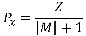 Z est la distance entre ledit plan d'image (IP) et ledit plan conjugué du capteur (CP) ;M est le grandissement dudit système optique.
 - Procédé selon la revendication 1, dans lequel la deuxième donnée de modélisation est une deuxième distance invariante Pα définie entre ledit plan d'image (IP) et un deuxième point de projection invariant (pα ) placé sur l'axe optique (OA) du dispositif d'imagerie, ladite deuxième distance invariante Pα satisfaisant la formule suivante :
 D est la distance entre ledit plan conjugué du capteur (CP) et la pupille d'entrée (EP) ;M est le grandissement du système optique.
 - Procédé selon l'une quelconque des revendications 1 à 3, dans lequel le deuxième paramètre intrinsèque (D) est estimé par étalonnage.
- Procédé selon l'une quelconque des revendications 1 à 3, dans lequel le deuxième paramètre intrinsèque (D) est estimé comme fonction du premier paramètre intrinsèque (Z) et d'un quatrième paramètre intrinsèque (E) dudit ensemble, représentatif d'une distance entre ledit plan d'image (IP) et la pupille d'entrée (EP).
- Procédé selon l'une quelconque des revendications 2 à 5, dans lequel l'ensemble de paramètres intrinsèques caractéristiques comprend en outre un cinquième paramètre intrinsèque représentatif d'une position de l'axe optique (OA) par rapport au plan d'image (IP).
- Procédé selon l'une quelconque des revendications 1 à 6, dans lequel l'ensemble de paramètres intrinsèques caractéristiques comprend en outre un sixième paramètre intrinsèque représentatif d'une dimension de la pupille d'entrée (E).
- Procédé selon l'une quelconque des revendications 1 à 7, dans lequel la configuration donnée dudit dispositif d'imagerie comprend un paramètre appartenant au groupe comprenant : un paramètre de focalisation, un paramètre de distance entre un plan principal du système optique et ledit plan d'image (IP).
- Programme informatique comprenant des instructions de code de programme pour la mise en oeuvre du procédé selon au moins l'une des revendications 1 à 8, lorsque ledit programme est exécuté sur un ordinateur ou un processeur.
- Support non transitoire lisible sur ordinateur stockant un produit de programme informatique selon la revendication 9.
- Dispositif de modélisation d'un dispositif d'imagerie comprenant un capteur d'images et un système optique, le capteur d'images étant placé dans un plan d'image (IP) du système optique, le système optique comprenant un diaphragme d'ouverture à iris définissant une pupille d'entrée du système optique, le dispositif comprenant, pour une configuration donnée dudit dispositif d'imagerie :- une unité de détermination configurée pour déterminer un ensemble de paramètres intrinsèques caractéristiques dudit dispositif d'imagerie, comprenant :* un premier paramètre intrinsèque (Z) représentatif d'une distance entre ledit plan d'image (IP) et un plan conjugué du capteur (CP) conjugué au capteur d'images par rapport au système optique ;* un deuxième paramètre intrinsèque (D) représentatif d'une distance entre ledit plan conjugué du capteur (CP) et la pupille d'entrée (E) ;* un troisième paramètre intrinsèque (M) représentatif d'un grandissement dudit système optique ;- une unité de détermination configurée pour déterminer une première donnée de modélisation (Px ) comme fonction desdits premier et troisième paramètres intrinsèques (Z, M) ;- une unité de détermination configurée pour déterminer une deuxième donnée de modélisation (Pα ) comme fonction desdits deuxième et troisième paramètres intrinsèques (D, M) ;- une unité de mappage configurée pour mapper un point 3D à un point image associé sur ledit capteur d'images (20) basé sur un modèle du dispositif d'imagerie obtenu comme fonction desdites première et deuxième données de modélisation (Px, Pα ).
- Dispositif selon la revendication 11, dans lequel la première donnée de modélisation comprend une première distance invariante Px définie entre ledit plan d'image (IP) et un premier point de projection invariant (px ) placé sur un axe optique (OA) dudit dispositif d'imagerie, ladite première distance invariante Px satisfaisant la formule suivante :
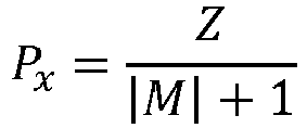 Z est la distance entre ledit plan d'image (IP) et ledit plan conjugué du capteur (CP) ;M est le grandissement dudit système optique.
 - Dispositif selon la revendication 11, dans lequel la deuxième donnée de modélisation est une deuxième distance invariante Pα définie entre ledit plan d'image (IP) et un deuxième point de projection invariant (pα ) placé sur l'axe optique (OA) du dispositif d'imagerie, ladite
deuxième distance invariante Pα satisfaisant la formule suivante : D est la distance entre ledit plan conjugué du capteur (CP) et la pupille d'entrée (EP) ;M est le grandissement du système optique.
 - Dispositif selon l'une quelconque des revendications 11 à 13, dans lequel le deuxième paramètre intrinsèque (D) est estimé par étalonnage.
- Dispositif selon l'une quelconque des revendications 11 à 13, dans lequel le deuxième paramètre intrinsèque (D) est estimé comme fonction du premier paramètre intrinsèque (Z) et d'un quatrième paramètre intrinsèque (E) dudit ensemble, représentatif d'une distance entre ledit plan d'image (IP) et la pupille d'entrée (EP).
Priority Applications (5)
| Application Number | Priority Date | Filing Date | Title |
|---|---|---|---|
| EP16306565.9A EP3327481B1 (fr) | 2016-11-28 | 2016-11-28 | Procédé de modélisation d'un dispositif d'imagerie, produit de programme informatique correspondant et support lisible par ordinateur |
| JP2017204449A JP2018164249A (ja) | 2016-11-28 | 2017-10-23 | 撮像装置をモデリングする方法、対応するコンピュータプログラム製品、及びコンピュータ可読担体媒体 |
| US15/809,627 US10489933B2 (en) | 2016-11-28 | 2017-11-10 | Method for modelling an image device, corresponding computer program product and computer-readable carrier medium |
| KR1020170158511A KR20180061021A (ko) | 2016-11-28 | 2017-11-24 | 이미징 디바이스를 모델링하는 방법, 대응하는 컴퓨터 프로그램 제품 및 컴퓨터 판독가능 캐리어 매체 |
| CN201711214075.XA CN108174179B (zh) | 2016-11-28 | 2017-11-28 | 用于对成像设备进行建模的方法和计算机可读存储介质 |
Applications Claiming Priority (1)
| Application Number | Priority Date | Filing Date | Title |
|---|---|---|---|
| EP16306565.9A EP3327481B1 (fr) | 2016-11-28 | 2016-11-28 | Procédé de modélisation d'un dispositif d'imagerie, produit de programme informatique correspondant et support lisible par ordinateur |
Publications (2)
| Publication Number | Publication Date |
|---|---|
| EP3327481A1 EP3327481A1 (fr) | 2018-05-30 |
| EP3327481B1 true EP3327481B1 (fr) | 2019-07-03 |
Family
ID=57517828
Family Applications (1)
| Application Number | Title | Priority Date | Filing Date |
|---|---|---|---|
| EP16306565.9A Active EP3327481B1 (fr) | 2016-11-28 | 2016-11-28 | Procédé de modélisation d'un dispositif d'imagerie, produit de programme informatique correspondant et support lisible par ordinateur |
Country Status (5)
| Country | Link |
|---|---|
| US (1) | US10489933B2 (fr) |
| EP (1) | EP3327481B1 (fr) |
| JP (1) | JP2018164249A (fr) |
| KR (1) | KR20180061021A (fr) |
| CN (1) | CN108174179B (fr) |
Families Citing this family (2)
| Publication number | Priority date | Publication date | Assignee | Title |
|---|---|---|---|---|
| US9703175B2 (en) * | 2015-07-02 | 2017-07-11 | Qualcomm Incorporated | Systems and methods for autofocus trigger |
| CN109697737B (zh) * | 2018-11-30 | 2021-08-17 | Oppo广东移动通信有限公司 | 摄像头标定方法、装置、电子设备和计算机可读存储介质 |
Family Cites Families (14)
| Publication number | Priority date | Publication date | Assignee | Title |
|---|---|---|---|---|
| CA1319188C (fr) * | 1989-08-24 | 1993-06-15 | Marc Rioux | Dispositif d'imagerie tridimensionnelle |
| US5661667A (en) * | 1994-03-14 | 1997-08-26 | Virtek Vision Corp. | 3D imaging using a laser projector |
| US5572363A (en) * | 1994-11-28 | 1996-11-05 | Fergason; James L. | Retro-reflector based in-line viewing system |
| US7612870B2 (en) * | 1998-02-25 | 2009-11-03 | California Institute Of Technology | Single-lens aperture-coded camera for three dimensional imaging in small volumes |
| US6594083B1 (en) * | 1999-06-15 | 2003-07-15 | Vizta 3D, Inc. | Lenticular imaging system, method and apparatus |
| JP2001142006A (ja) * | 1999-11-16 | 2001-05-25 | Minolta Co Ltd | 接眼光学系と映像表示装置 |
| JP4541523B2 (ja) * | 2000-10-10 | 2010-09-08 | キヤノン株式会社 | マルチビーム光走査光学系及びマルチビーム光走査装置及び画像形成装置 |
| US7068815B2 (en) * | 2003-06-13 | 2006-06-27 | Sarnoff Corporation | Method and apparatus for ground detection and removal in vision systems |
| DE10359415A1 (de) * | 2003-12-16 | 2005-07-14 | Trimble Jena Gmbh | Verfahren zur Kalibrierung eines Vermessungsgeräts |
| CA2684602A1 (fr) * | 2007-04-23 | 2008-11-06 | California Institute Of Technology | Dispositif d'imagerie en 3d a lentille unique mettant en oeuvre une combinaison formee d'un masque d'ouverture code par polarisation et d'uncap teur sensible a la polarisation |
| EP2502208A2 (fr) * | 2009-11-19 | 2012-09-26 | Ocali Bilisim Teknolojileri Yazilim Donanim San. Tic. A.S. | Dessin en 3-d directement à l'aide de contraintes de vues de caméra |
| WO2014107434A1 (fr) * | 2013-01-02 | 2014-07-10 | California Institute Of Technology | Système monocapteur permettant d'extraire des informations de profondeur d'un flou d'image |
| CN103716538B (zh) * | 2013-12-16 | 2017-01-25 | 天津大学 | 一种基于dmd的成像前处理装置和方法 |
| US20170094251A1 (en) * | 2015-09-30 | 2017-03-30 | Faro Technologies, Inc. | Three-dimensional imager that includes a dichroic camera |
-
2016
- 2016-11-28 EP EP16306565.9A patent/EP3327481B1/fr active Active
-
2017
- 2017-10-23 JP JP2017204449A patent/JP2018164249A/ja active Pending
- 2017-11-10 US US15/809,627 patent/US10489933B2/en active Active
- 2017-11-24 KR KR1020170158511A patent/KR20180061021A/ko not_active Withdrawn
- 2017-11-28 CN CN201711214075.XA patent/CN108174179B/zh active Active
Non-Patent Citations (1)
| Title |
|---|
| None * |
Also Published As
| Publication number | Publication date |
|---|---|
| CN108174179A (zh) | 2018-06-15 |
| CN108174179B (zh) | 2021-06-01 |
| KR20180061021A (ko) | 2018-06-07 |
| US10489933B2 (en) | 2019-11-26 |
| US20180150975A1 (en) | 2018-05-31 |
| JP2018164249A (ja) | 2018-10-18 |
| EP3327481A1 (fr) | 2018-05-30 |
Similar Documents
| Publication | Publication Date | Title |
|---|---|---|
| US10334229B2 (en) | Method for obtaining a refocused image from a 4D raw light field data using a shift correction parameter | |
| CN109118470B (zh) | 一种图像质量评价方法、装置、终端和服务器 | |
| CN102072706B (zh) | 一种多相机定位与跟踪方法及系统 | |
| US20180014003A1 (en) | Measuring Accuracy of Image Based Depth Sensing Systems | |
| CN104424640B (zh) | 对图像进行虚化处理的方法和装置 | |
| TW201709718A (zh) | 在使用者裝置上顯示光場為基影像之方法及裝置,及對應之電腦程式產品 | |
| US12153732B2 (en) | Gaze point estimation method, device, and electronic device | |
| CN115035235B (zh) | 三维重建方法及装置 | |
| CN114511608A (zh) | 一种深度图像的获取方法、装置、终端、成像系统和介质 | |
| CN110782412A (zh) | 图像处理方法及装置、处理器、电子设备及存储介质 | |
| CN107590444A (zh) | 静态障碍物的检测方法、装置及存储介质 | |
| CN106952247A (zh) | 一种双摄像头终端及其图像处理方法和系统 | |
| EP3327481B1 (fr) | Procédé de modélisation d'un dispositif d'imagerie, produit de programme informatique correspondant et support lisible par ordinateur | |
| JP2016114445A (ja) | 3次元位置算出装置およびそのプログラム、ならびに、cg合成装置 | |
| KR20180000696A (ko) | 적어도 하나의 라이트필드 카메라를 사용하여 입체 이미지 쌍을 생성하는 방법 및 장치 | |
| CN108009576A (zh) | 一种目标匹配的物体识别方法、设备及存储设备 | |
| CN105335959A (zh) | 成像装置快速对焦方法及其设备 | |
| CN108151647A (zh) | 一种图像数据处理方法、装置及移动终端 | |
| CN103310482A (zh) | 一种三维重建方法及系统 | |
| US20200410635A1 (en) | Consistently editing light field data | |
| CN115834860B (zh) | 背景虚化方法、装置、设备、存储介质和程序产品 | |
| CN110853087B (zh) | 一种视差估计方法、装置、存储介质及终端 | |
| Morinaga et al. | Underwater active oneshot scan with static wave pattern and bundle adjustment | |
| CN114549627A (zh) | 一种对目标测距的方法、装置、图像采集设备及介质 | |
| EP3761260A1 (fr) | Stockage et signalisation de paramètres de pupille d'entrée pour média immersif |
Legal Events
| Date | Code | Title | Description |
|---|---|---|---|
| PUAI | Public reference made under article 153(3) epc to a published international application that has entered the european phase |
Free format text: ORIGINAL CODE: 0009012 |
|
| STAA | Information on the status of an ep patent application or granted ep patent |
Free format text: STATUS: THE APPLICATION HAS BEEN PUBLISHED |
|
| AK | Designated contracting states |
Kind code of ref document: A1 Designated state(s): AL AT BE BG CH CY CZ DE DK EE ES FI FR GB GR HR HU IE IS IT LI LT LU LV MC MK MT NL NO PL PT RO RS SE SI SK SM TR |
|
| AX | Request for extension of the european patent |
Extension state: BA ME |
|
| STAA | Information on the status of an ep patent application or granted ep patent |
Free format text: STATUS: REQUEST FOR EXAMINATION WAS MADE |
|
| 17P | Request for examination filed |
Effective date: 20181121 |
|
| RBV | Designated contracting states (corrected) |
Designated state(s): AL AT BE BG CH CY CZ DE DK EE ES FI FR GB GR HR HU IE IS IT LI LT LU LV MC MK MT NL NO PL PT RO RS SE SI SK SM TR |
|
| GRAP | Despatch of communication of intention to grant a patent |
Free format text: ORIGINAL CODE: EPIDOSNIGR1 |
|
| STAA | Information on the status of an ep patent application or granted ep patent |
Free format text: STATUS: GRANT OF PATENT IS INTENDED |
|
| INTG | Intention to grant announced |
Effective date: 20190117 |
|
| RAP1 | Party data changed (applicant data changed or rights of an application transferred) |
Owner name: INTERDIGITAL CE PATENT HOLDINGS |
|
| GRAS | Grant fee paid |
Free format text: ORIGINAL CODE: EPIDOSNIGR3 |
|
| GRAA | (expected) grant |
Free format text: ORIGINAL CODE: 0009210 |
|
| STAA | Information on the status of an ep patent application or granted ep patent |
Free format text: STATUS: THE PATENT HAS BEEN GRANTED |
|
| AK | Designated contracting states |
Kind code of ref document: B1 Designated state(s): AL AT BE BG CH CY CZ DE DK EE ES FI FR GB GR HR HU IE IS IT LI LT LU LV MC MK MT NL NO PL PT RO RS SE SI SK SM TR |
|
| REG | Reference to a national code |
Ref country code: GB Ref legal event code: FG4D |
|
| REG | Reference to a national code |
Ref country code: CH Ref legal event code: EP Ref country code: AT Ref legal event code: REF Ref document number: 1151696 Country of ref document: AT Kind code of ref document: T Effective date: 20190715 |
|
| REG | Reference to a national code |
Ref country code: IE Ref legal event code: FG4D |
|
| REG | Reference to a national code |
Ref country code: DE Ref legal event code: R096 Ref document number: 602016016238 Country of ref document: DE |
|
| REG | Reference to a national code |
Ref country code: NL Ref legal event code: MP Effective date: 20190703 |
|
| REG | Reference to a national code |
Ref country code: LT Ref legal event code: MG4D |
|
| REG | Reference to a national code |
Ref country code: AT Ref legal event code: MK05 Ref document number: 1151696 Country of ref document: AT Kind code of ref document: T Effective date: 20190703 |
|
| PG25 | Lapsed in a contracting state [announced via postgrant information from national office to epo] |
Ref country code: NO Free format text: LAPSE BECAUSE OF FAILURE TO SUBMIT A TRANSLATION OF THE DESCRIPTION OR TO PAY THE FEE WITHIN THE PRESCRIBED TIME-LIMIT Effective date: 20191003 Ref country code: AT Free format text: LAPSE BECAUSE OF FAILURE TO SUBMIT A TRANSLATION OF THE DESCRIPTION OR TO PAY THE FEE WITHIN THE PRESCRIBED TIME-LIMIT Effective date: 20190703 Ref country code: SE Free format text: LAPSE BECAUSE OF FAILURE TO SUBMIT A TRANSLATION OF THE DESCRIPTION OR TO PAY THE FEE WITHIN THE PRESCRIBED TIME-LIMIT Effective date: 20190703 Ref country code: FI Free format text: LAPSE BECAUSE OF FAILURE TO SUBMIT A TRANSLATION OF THE DESCRIPTION OR TO PAY THE FEE WITHIN THE PRESCRIBED TIME-LIMIT Effective date: 20190703 Ref country code: HR Free format text: LAPSE BECAUSE OF FAILURE TO SUBMIT A TRANSLATION OF THE DESCRIPTION OR TO PAY THE FEE WITHIN THE PRESCRIBED TIME-LIMIT Effective date: 20190703 Ref country code: PT Free format text: LAPSE BECAUSE OF FAILURE TO SUBMIT A TRANSLATION OF THE DESCRIPTION OR TO PAY THE FEE WITHIN THE PRESCRIBED TIME-LIMIT Effective date: 20191104 Ref country code: BG Free format text: LAPSE BECAUSE OF FAILURE TO SUBMIT A TRANSLATION OF THE DESCRIPTION OR TO PAY THE FEE WITHIN THE PRESCRIBED TIME-LIMIT Effective date: 20191003 Ref country code: LT Free format text: LAPSE BECAUSE OF FAILURE TO SUBMIT A TRANSLATION OF THE DESCRIPTION OR TO PAY THE FEE WITHIN THE PRESCRIBED TIME-LIMIT Effective date: 20190703 Ref country code: NL Free format text: LAPSE BECAUSE OF FAILURE TO SUBMIT A TRANSLATION OF THE DESCRIPTION OR TO PAY THE FEE WITHIN THE PRESCRIBED TIME-LIMIT Effective date: 20190703 Ref country code: CZ Free format text: LAPSE BECAUSE OF FAILURE TO SUBMIT A TRANSLATION OF THE DESCRIPTION OR TO PAY THE FEE WITHIN THE PRESCRIBED TIME-LIMIT Effective date: 20190703 |
|
| PG25 | Lapsed in a contracting state [announced via postgrant information from national office to epo] |
Ref country code: AL Free format text: LAPSE BECAUSE OF FAILURE TO SUBMIT A TRANSLATION OF THE DESCRIPTION OR TO PAY THE FEE WITHIN THE PRESCRIBED TIME-LIMIT Effective date: 20190703 Ref country code: GR Free format text: LAPSE BECAUSE OF FAILURE TO SUBMIT A TRANSLATION OF THE DESCRIPTION OR TO PAY THE FEE WITHIN THE PRESCRIBED TIME-LIMIT Effective date: 20191004 Ref country code: ES Free format text: LAPSE BECAUSE OF FAILURE TO SUBMIT A TRANSLATION OF THE DESCRIPTION OR TO PAY THE FEE WITHIN THE PRESCRIBED TIME-LIMIT Effective date: 20190703 Ref country code: LV Free format text: LAPSE BECAUSE OF FAILURE TO SUBMIT A TRANSLATION OF THE DESCRIPTION OR TO PAY THE FEE WITHIN THE PRESCRIBED TIME-LIMIT Effective date: 20190703 Ref country code: RS Free format text: LAPSE BECAUSE OF FAILURE TO SUBMIT A TRANSLATION OF THE DESCRIPTION OR TO PAY THE FEE WITHIN THE PRESCRIBED TIME-LIMIT Effective date: 20190703 Ref country code: IS Free format text: LAPSE BECAUSE OF FAILURE TO SUBMIT A TRANSLATION OF THE DESCRIPTION OR TO PAY THE FEE WITHIN THE PRESCRIBED TIME-LIMIT Effective date: 20191103 |
|
| PG25 | Lapsed in a contracting state [announced via postgrant information from national office to epo] |
Ref country code: TR Free format text: LAPSE BECAUSE OF FAILURE TO SUBMIT A TRANSLATION OF THE DESCRIPTION OR TO PAY THE FEE WITHIN THE PRESCRIBED TIME-LIMIT Effective date: 20190703 |
|
| PG25 | Lapsed in a contracting state [announced via postgrant information from national office to epo] |
Ref country code: RO Free format text: LAPSE BECAUSE OF FAILURE TO SUBMIT A TRANSLATION OF THE DESCRIPTION OR TO PAY THE FEE WITHIN THE PRESCRIBED TIME-LIMIT Effective date: 20190703 Ref country code: PL Free format text: LAPSE BECAUSE OF FAILURE TO SUBMIT A TRANSLATION OF THE DESCRIPTION OR TO PAY THE FEE WITHIN THE PRESCRIBED TIME-LIMIT Effective date: 20190703 Ref country code: EE Free format text: LAPSE BECAUSE OF FAILURE TO SUBMIT A TRANSLATION OF THE DESCRIPTION OR TO PAY THE FEE WITHIN THE PRESCRIBED TIME-LIMIT Effective date: 20190703 Ref country code: DK Free format text: LAPSE BECAUSE OF FAILURE TO SUBMIT A TRANSLATION OF THE DESCRIPTION OR TO PAY THE FEE WITHIN THE PRESCRIBED TIME-LIMIT Effective date: 20190703 Ref country code: IT Free format text: LAPSE BECAUSE OF FAILURE TO SUBMIT A TRANSLATION OF THE DESCRIPTION OR TO PAY THE FEE WITHIN THE PRESCRIBED TIME-LIMIT Effective date: 20190703 |
|
| PG25 | Lapsed in a contracting state [announced via postgrant information from national office to epo] |
Ref country code: SM Free format text: LAPSE BECAUSE OF FAILURE TO SUBMIT A TRANSLATION OF THE DESCRIPTION OR TO PAY THE FEE WITHIN THE PRESCRIBED TIME-LIMIT Effective date: 20190703 Ref country code: IS Free format text: LAPSE BECAUSE OF FAILURE TO SUBMIT A TRANSLATION OF THE DESCRIPTION OR TO PAY THE FEE WITHIN THE PRESCRIBED TIME-LIMIT Effective date: 20200224 Ref country code: SK Free format text: LAPSE BECAUSE OF FAILURE TO SUBMIT A TRANSLATION OF THE DESCRIPTION OR TO PAY THE FEE WITHIN THE PRESCRIBED TIME-LIMIT Effective date: 20190703 |
|
| REG | Reference to a national code |
Ref country code: DE Ref legal event code: R097 Ref document number: 602016016238 Country of ref document: DE |
|
| REG | Reference to a national code |
Ref country code: CH Ref legal event code: PL |
|
| PLBE | No opposition filed within time limit |
Free format text: ORIGINAL CODE: 0009261 |
|
| STAA | Information on the status of an ep patent application or granted ep patent |
Free format text: STATUS: NO OPPOSITION FILED WITHIN TIME LIMIT |
|
| PG2D | Information on lapse in contracting state deleted |
Ref country code: IS |
|
| PG25 | Lapsed in a contracting state [announced via postgrant information from national office to epo] |
Ref country code: LU Free format text: LAPSE BECAUSE OF NON-PAYMENT OF DUE FEES Effective date: 20191128 Ref country code: CH Free format text: LAPSE BECAUSE OF NON-PAYMENT OF DUE FEES Effective date: 20191130 Ref country code: MC Free format text: LAPSE BECAUSE OF FAILURE TO SUBMIT A TRANSLATION OF THE DESCRIPTION OR TO PAY THE FEE WITHIN THE PRESCRIBED TIME-LIMIT Effective date: 20190703 Ref country code: LI Free format text: LAPSE BECAUSE OF NON-PAYMENT OF DUE FEES Effective date: 20191130 |
|
| 26N | No opposition filed |
Effective date: 20200603 |
|
| REG | Reference to a national code |
Ref country code: BE Ref legal event code: MM Effective date: 20191130 |
|
| PG25 | Lapsed in a contracting state [announced via postgrant information from national office to epo] |
Ref country code: SI Free format text: LAPSE BECAUSE OF FAILURE TO SUBMIT A TRANSLATION OF THE DESCRIPTION OR TO PAY THE FEE WITHIN THE PRESCRIBED TIME-LIMIT Effective date: 20190703 |
|
| PG25 | Lapsed in a contracting state [announced via postgrant information from national office to epo] |
Ref country code: IE Free format text: LAPSE BECAUSE OF NON-PAYMENT OF DUE FEES Effective date: 20191128 |
|
| PG25 | Lapsed in a contracting state [announced via postgrant information from national office to epo] |
Ref country code: BE Free format text: LAPSE BECAUSE OF NON-PAYMENT OF DUE FEES Effective date: 20191130 |
|
| PG25 | Lapsed in a contracting state [announced via postgrant information from national office to epo] |
Ref country code: CY Free format text: LAPSE BECAUSE OF FAILURE TO SUBMIT A TRANSLATION OF THE DESCRIPTION OR TO PAY THE FEE WITHIN THE PRESCRIBED TIME-LIMIT Effective date: 20190703 |
|
| GBPC | Gb: european patent ceased through non-payment of renewal fee |
Effective date: 20201128 |
|
| PG25 | Lapsed in a contracting state [announced via postgrant information from national office to epo] |
Ref country code: HU Free format text: LAPSE BECAUSE OF FAILURE TO SUBMIT A TRANSLATION OF THE DESCRIPTION OR TO PAY THE FEE WITHIN THE PRESCRIBED TIME-LIMIT; INVALID AB INITIO Effective date: 20161128 Ref country code: MT Free format text: LAPSE BECAUSE OF FAILURE TO SUBMIT A TRANSLATION OF THE DESCRIPTION OR TO PAY THE FEE WITHIN THE PRESCRIBED TIME-LIMIT Effective date: 20190703 |
|
| PG25 | Lapsed in a contracting state [announced via postgrant information from national office to epo] |
Ref country code: GB Free format text: LAPSE BECAUSE OF NON-PAYMENT OF DUE FEES Effective date: 20201128 |
|
| PG25 | Lapsed in a contracting state [announced via postgrant information from national office to epo] |
Ref country code: MK Free format text: LAPSE BECAUSE OF FAILURE TO SUBMIT A TRANSLATION OF THE DESCRIPTION OR TO PAY THE FEE WITHIN THE PRESCRIBED TIME-LIMIT Effective date: 20190703 |
|
| P01 | Opt-out of the competence of the unified patent court (upc) registered |
Effective date: 20230511 |
|
| PGFP | Annual fee paid to national office [announced via postgrant information from national office to epo] |
Ref country code: DE Payment date: 20251126 Year of fee payment: 10 |
|
| PGFP | Annual fee paid to national office [announced via postgrant information from national office to epo] |
Ref country code: FR Payment date: 20251125 Year of fee payment: 10 |