EP3327527A1 - Unbemannte fahrzeuge zur datenerfassung in industrieanlagen - Google Patents
Unbemannte fahrzeuge zur datenerfassung in industrieanlagen Download PDFInfo
- Publication number
- EP3327527A1 EP3327527A1 EP17201131.4A EP17201131A EP3327527A1 EP 3327527 A1 EP3327527 A1 EP 3327527A1 EP 17201131 A EP17201131 A EP 17201131A EP 3327527 A1 EP3327527 A1 EP 3327527A1
- Authority
- EP
- European Patent Office
- Prior art keywords
- data
- unmanned vehicle
- transmitting
- communication
- exchange
- Prior art date
- Legal status (The legal status is an assumption and is not a legal conclusion. Google has not performed a legal analysis and makes no representation as to the accuracy of the status listed.)
- Granted
Links
Images


Classifications
-
- G—PHYSICS
- G05—CONTROLLING; REGULATING
- G05B—CONTROL OR REGULATING SYSTEMS IN GENERAL; FUNCTIONAL ELEMENTS OF SUCH SYSTEMS; MONITORING OR TESTING ARRANGEMENTS FOR SUCH SYSTEMS OR ELEMENTS
- G05B19/00—Program-control systems
- G05B19/02—Program-control systems electric
- G05B19/418—Total factory control, i.e. centrally controlling a plurality of machines, e.g. direct or distributed numerical control [DNC], flexible manufacturing systems [FMS], integrated manufacturing systems [IMS] or computer integrated manufacturing [CIM]
- G05B19/4189—Total factory control, i.e. centrally controlling a plurality of machines, e.g. direct or distributed numerical control [DNC], flexible manufacturing systems [FMS], integrated manufacturing systems [IMS] or computer integrated manufacturing [CIM] characterised by the transport system
- G05B19/41895—Total factory control, i.e. centrally controlling a plurality of machines, e.g. direct or distributed numerical control [DNC], flexible manufacturing systems [FMS], integrated manufacturing systems [IMS] or computer integrated manufacturing [CIM] characterised by the transport system using automatic guided vehicles [AGV]
-
- G—PHYSICS
- G05—CONTROLLING; REGULATING
- G05B—CONTROL OR REGULATING SYSTEMS IN GENERAL; FUNCTIONAL ELEMENTS OF SUCH SYSTEMS; MONITORING OR TESTING ARRANGEMENTS FOR SUCH SYSTEMS OR ELEMENTS
- G05B19/00—Program-control systems
- G05B19/02—Program-control systems electric
- G05B19/418—Total factory control, i.e. centrally controlling a plurality of machines, e.g. direct or distributed numerical control [DNC], flexible manufacturing systems [FMS], integrated manufacturing systems [IMS] or computer integrated manufacturing [CIM]
- G05B19/4185—Total factory control, i.e. centrally controlling a plurality of machines, e.g. direct or distributed numerical control [DNC], flexible manufacturing systems [FMS], integrated manufacturing systems [IMS] or computer integrated manufacturing [CIM] characterised by the network communication
-
- H—ELECTRICITY
- H04—ELECTRIC COMMUNICATION TECHNIQUE
- H04W—WIRELESS COMMUNICATION NETWORKS
- H04W4/00—Services specially adapted for wireless communication networks; Facilities therefor
- H04W4/30—Services specially adapted for particular environments, situations or purposes
- H04W4/38—Services specially adapted for particular environments, situations or purposes for collecting sensor information
-
- H—ELECTRICITY
- H04—ELECTRIC COMMUNICATION TECHNIQUE
- H04W—WIRELESS COMMUNICATION NETWORKS
- H04W4/00—Services specially adapted for wireless communication networks; Facilities therefor
- H04W4/30—Services specially adapted for particular environments, situations or purposes
- H04W4/40—Services specially adapted for particular environments, situations or purposes for vehicles, e.g. vehicle-to-pedestrians [V2P]
-
- H—ELECTRICITY
- H04—ELECTRIC COMMUNICATION TECHNIQUE
- H04W—WIRELESS COMMUNICATION NETWORKS
- H04W4/00—Services specially adapted for wireless communication networks; Facilities therefor
- H04W4/80—Services using short range communication, e.g. near-field communication [NFC], radio-frequency identification [RFID] or low energy communication
-
- H—ELECTRICITY
- H04—ELECTRIC COMMUNICATION TECHNIQUE
- H04L—TRANSMISSION OF DIGITAL INFORMATION, e.g. TELEGRAPHIC COMMUNICATION
- H04L67/00—Network arrangements or protocols for supporting network services or applications
- H04L67/01—Protocols
- H04L67/12—Protocols specially adapted for proprietary or special-purpose networking environments, e.g. medical networks, sensor networks, networks in vehicles or remote metering networks
-
- Y—GENERAL TAGGING OF NEW TECHNOLOGICAL DEVELOPMENTS; GENERAL TAGGING OF CROSS-SECTIONAL TECHNOLOGIES SPANNING OVER SEVERAL SECTIONS OF THE IPC; TECHNICAL SUBJECTS COVERED BY FORMER USPC CROSS-REFERENCE ART COLLECTIONS [XRACs] AND DIGESTS
- Y02—TECHNOLOGIES OR APPLICATIONS FOR MITIGATION OR ADAPTATION AGAINST CLIMATE CHANGE
- Y02P—CLIMATE CHANGE MITIGATION TECHNOLOGIES IN THE PRODUCTION OR PROCESSING OF GOODS
- Y02P90/00—Enabling technologies with a potential contribution to greenhouse gas [GHG] emissions mitigation
- Y02P90/02—Total factory control, e.g. smart factories, flexible manufacturing systems [FMS] or integrated manufacturing systems [IMS]
-
- Y—GENERAL TAGGING OF NEW TECHNOLOGICAL DEVELOPMENTS; GENERAL TAGGING OF CROSS-SECTIONAL TECHNOLOGIES SPANNING OVER SEVERAL SECTIONS OF THE IPC; TECHNICAL SUBJECTS COVERED BY FORMER USPC CROSS-REFERENCE ART COLLECTIONS [XRACs] AND DIGESTS
- Y02—TECHNOLOGIES OR APPLICATIONS FOR MITIGATION OR ADAPTATION AGAINST CLIMATE CHANGE
- Y02P—CLIMATE CHANGE MITIGATION TECHNOLOGIES IN THE PRODUCTION OR PROCESSING OF GOODS
- Y02P90/00—Enabling technologies with a potential contribution to greenhouse gas [GHG] emissions mitigation
- Y02P90/60—Electric or hybrid propulsion means for production processes
Definitions
- the invention relates to a method and a system for data acquisition in an industrial plant, in particular a metallurgical plant, such as a cold or hot rolling mill, a strip processing plant or a steel mill.
- a metallurgical plant such as a cold or hot rolling mill, a strip processing plant or a steel mill.
- An object of the invention is to provide a method and a system for data acquisition in an industrial plant, in particular a metallurgical plant, which the susceptibility to malfunction by Reduce communication errors and enable efficient data exchange.
- the method according to the invention is designed for data acquisition in an industrial plant in which data is preferably exchanged wirelessly between plant components, the operating personnel and so on.
- the method is used in a metallurgical plant, particularly preferably in a cold or hot rolling mill, a strip processing plant or a steelworks, since in such plants a high data traffic prevails, recorded a variety of measurement signals, exchanged and the control of the system are based ,
- At least one unmanned vehicle also referred to as "UF" which has a transmitting and receiving device for transmitting and receiving data.
- one or more communication partners also referred to as “KP” are provided, each of which has a transmitting and / or receiving device for transmitting and / or receiving data.
- the transmitting and receiving devices are in this case set up, that is coordinated with one another in order to exchange data between the unmanned vehicle and the communication partner.
- the unmanned vehicle goes to a transmission location close to the communication partner in order to subsequently exchange the data.
- the UF and / or the KP preferably have a device for storing data, particularly preferably for the temporary storage of data.
- the unmanned vehicle and / or the communication partner can exchange and record a time and / or place stamp and / or a component ID.
- a time and / or place stamps and / or a component ID can be logged during the communication, preferably from the UF or from both communication partners.
- the UF and / or the KP preferably has a device for storing data. This is z. B. ensures that the data are available even after the end of the communication and can be further processed, for example, in a later step.
- the transmission location can be a well-defined location in the immediate vicinity of the communication partner, but the transmission location can also be an area within which interference-free communication is ensured.
- the logged-in place stamp is suitable in this context to identify the transmission location, and possibly also additionally the communication partner (s).
- the unmanned Vehicle targeted in the environment of a communication partner, ie at the transmission location to realize the data exchange over a relatively short distance. This ensures secure and reliable data transmission.
- the data transmission is not or only slightly influenced by the data traffic in the "background" of the industrial plant. It is ensured, due to the proximity between the UF and the KP, that no communication disturbance occurs even in the case of an intended or unintended use of an already occupied frequency.
- the disruption of the radio traffic is an aspect here.
- Another is that, for example, in Bluetooth, the transmission distance is very limited and is additionally affected by a lot of metal in the industrial plant.
- the data transmission between the UF and KP is preferably wireless.
- the UF and the KP come into physical contact for particularly secure transmission.
- the UF and the KP can be equipped, for example, with one or more suitable plug connections and / or contact points.
- At least one of the communication partners is a component of an industrial plant, which is set up so that it can independently record operating data, preferably process it and transmit it to the unmanned vehicle located at the transmission location.
- a component is for example in question: a role, such as a work roll, support roller or transport roller in a rolling mill, a drive device, such as an electric motor, a pivot bearing, etc.
- the transmitting and / or receiving means of the component or the plurality of components are preferably each Devices, such as sensors with data processing unit associated with and connected to these physically or wirelessly, which are set up so that they can record operating data independently and possibly edit, such as digitize. In this way, the reliability of the production process of the industrial plant can be increased because the UF-based data exchange reduces communication disruptions in the area of process monitoring and process control.
- the unmanned vehicle has a battery as an electrical energy source for the operation of the same, wherein at the transfer location preferably a charging device for automatically charging the battery or a device for automatic replacement of the battery is provided.
- the communication time between the UF and the KP can be effectively used for charging the battery or exchanging it.
- the UF can also use another, self-sufficient energy source or drive source, eg. B. an internal combustion engine or z. B. in the case of a rail-bound UF a permanent source of energy.
- the "operation" of the UF includes at least the autonomous movement in the industrial plant and the data exchange with the corresponding KP.
- a landing platform can be provided at the transmission location, where the unmanned aerial vehicle lands for data exchange, thereby saving the battery.
- the landing platform can be equipped with the mentioned charging device or the device for replacing the battery.
- the unmanned vehicle is arranged to exchange data with a plurality of communication partners from one transmission location, thereby facilitating data exchange, i.
- the "collecting" or “distribution” of data can be done very efficiently. Any use of component IDs and / or time and / or location stamps makes it possible to assign the data to the respective KP.
- a plurality of communication partners are provided, one of which is a base adapted to process data received from the UF for monitoring and / or controlling the production process of the industrial plant.
- the UF serves as a "mobile repeater" to increase range.
- the UF may be arranged to allow communication between multiple KPs so that the UF acts as a "mobile repeater" between multiple KPs, allowing the KPs to share data with one another and, if necessary, to coordinate with each other.
- the production process can be coordinated with one another.
- One or more KPs may be mobile terminals through which a UF may also communicate with a human, such as an operator.
- a plurality of communication partners are provided, wherein at least one of the communication partners is another unmanned vehicle.
- a plurality of UF arranged as a "swarm" can stay between a first KP, for example a first component, and a last KP, for example a base.
- the UFs can optionally exchange information with other KPs, such as components, and, if appropriate, forward them along the UF chain to the base.
- the UF can be used to relay, amplify, bundle, distribute, and / or process information over a long distance, without disturbing the rest of the radio traffic, and without the individual UFs having to cover large distances Collect data from the communication partners.
- the UF can land on or visit special landing pads or dock at certain resting places to save energy or recharge, and thus they do not have to be constantly in motion.
- the transmission power of the unmanned vehicle is greater than that of the communication partner, whereby the UF can forward the data collected by the KP over a relatively greater distance, for example to the base or another UF.
- the unmanned vehicle is set up so that it can adapt the transmission channel, such as the radio frequency, for data exchange.
- the transmission channel such as the radio frequency
- the adaptation of the transmission channel can be done, for example, depending on the communication partner and / or the location of the unmanned vehicle and / or the removal of the unmanned vehicle to the communication partner and / or the free transmission channels in the industrial plant and / or the amount of data to be transmitted.
- the above object is further achieved by a system for data acquisition in an industrial plant in which data is preferably exchanged wirelessly.
- the system such as the process, is used in a metallurgical plant, more preferably in a cold or hot rolling mill, a strip processing plant or a steel mill.
- the system comprises at least one unmanned vehicle having a transmitting and receiving device for transmitting and receiving data, and one or more communication partners, each having a transmitting and / or receiving device for transmitting and / or receiving data.
- the transceivers are arranged to exchange data between the unmanned vehicle and the communication partner, the system being arranged to perform a method according to any one of the preceding claims.
- the described methods and systems are preferably used in metallurgical plants, in particular cold or hot rolling mills, steel mills or strip plants.
- the invention can also be used in other industrial plants, provided that a reliable data exchange between machines, components and / or data processing devices is to be carried out, in particular in an environment of high data traffic.
- the Figures 1A and 1B schematically show the use of an unmanned vehicle (hereinafter also referred to as "UF") 10 for exchanging information with a communication partner (hereinafter also referred to as "KP") in an industrial plant.
- UF unmanned vehicle
- KP communication partner
- a KP for example, a machine, a component of an industrial plant, a component, etc., may function in an industrial plant, which will be collectively referred to as “component” or “component” for simplicity, and will be designated by the reference numeral 20.
- the components 20 each have one or more transmitting and / or receiving devices 21, 22, 23 in order to exchange operating data with the UF 10.
- you can Other devices may be communication partners for the UF 10, for example a base 30, further UFs 10, which are described in detail below, and / or mobile terminals via which a UF 10 may also communicate with a human, such as an operator.
- the transmitting and receiving devices 21, 22, 23 are each associated with devices (such as sensors with data processing unit) and connected to them physically or wirelessly, which are set up so that they z.
- one or more components 20, in particular their data processing units to be set up so that further data can be calculated on these models, for example from the operating data, for example a model that allows conclusions to be drawn about possible damage.
- Suitable UF 10s are: flying UF, such as multicopters; so-called “unmanned aerial vehicles”; “Micro Aerial Vehicles”; moving UFs that are free-moving or guided, such as on rails; floating, diving UF; Hybrid UF etc.
- the UF 10 moves to a transmission location close to the communication with the component 20.
- a defined location can be specified as the transmission location or an area.
- the UF 10 can exchange unidirectional or bidirectional information with it.
- This information also includes, for example, a time and / or place stamp and / or a component ID. Due to the optional bidirectional use of time and / or place stamps and / or a component ID, especially in a further processing of the data, for. B. by a process control system, to ensure that the data assigned to the right communication partner, that is, the right system component become.
- the use of component IDs can ensure that only authorized components communicate with each other, so that eg. B. the possibility of industrial espionage is at least reduced.
- the time and / or place stamp as well as the component ID are preferably logged during the communication, advantageously from both communication partners, but preferably from the UF.
- the UF Since the exchanged and logged data from a KP does not necessarily have to be transferred directly from the UF to another communication partner, the UF has a device for storing the data, advantageously also the KP. This is z. B. ensures that the data are available even after the end of the communication and can be further processed, for example, in a later step.
- the UF 10 and the component 20 are equipped with matched transmitting and / or receiving units 21, 22, 23, which particularly preferably transmit and receive only over a short distance, so as to reduce the "radio contamination" and the energy consumption of the transmitting and receiving devices low in the industrial plant.
- the UF 10 moves purposefully into the environment of a component 20 in order to realize the data exchange over a short distance. This not only reduces the risk of radio interference, but also the transmission powers can be reduced.
- the communication may also be through a physical connection between the UF 10 and the KP.
- FIG. 1A and 1B The communication between a UF 10 and the KP is shown in the figures by means of arrows.
- the defined location may be a platform or docking point 11 as shown in FIG FIG. 1B evident.
- a flying UF 10 would then not float in the air during the data exchange, but could land on the platform 11 and so for example, the battery, charge or replace.
- the platform 11 may be equipped with a device for replacing the battery or with a charging device.
- the battery can be charged by a physical electrical connection or wirelessly.
- the UF 10 After the UF 10 has received information from one or more components 20, it may move to another location, such as another location for exchanging information with one or more other components 20 or a base 30, which may receive the received information, e.g. , B. for monitoring and control of the production process, further processed.
- Another location such as another location for exchanging information with one or more other components 20 or a base 30, which may receive the received information, e.g. , B. for monitoring and control of the production process, further processed.
- the "gathering" or “distribution" of data from and to the components 20 and the transport to a base 30 are out of the Figures 3 and 4 out.
- the UF 10 may be arranged to allow communication between multiple KPs so that the UF 10 acts as a "mobile repeater" between multiple KPs, allowing the KPs to communicate with each other and possibly coordinate with each other.
- a UF 10 transfers data from one KP to one or more other KP and so on makes a communication between one or more KP, in particular, the production process can be coordinated with each other.
- the collected data can be transferred to further processes, for example to a process control system. Subsequently, the UF 10 can go to other transmission locations in the industrial plant to exchange data with communication partners again. It should be appreciated that the base 30 may also be equipped with a platform or docking location, as described above with respect to the platform / docking point 11.
- the UF 10 has a greater radio power than the component 20, whereby it from a greater distance (compared to the component 20) z. B. can communicate with the base 30 or a mobile terminal without the rest of the radio traffic is disturbed.
- the disruption of the radio traffic is an aspect here.
- Another is that, for example, in Bluetooth, the transmission distance is very limited and is additionally affected by a lot of metal in the industrial plant.
- the UF 10 may use the same radio frequency as for replacement with the component 20. In this case, the UF 10 acts as a "mobile repeater" to increase the range. Alternatively, different frequencies can be used.
- the UF 10 can also communicate with other UF 10, as in the FIG. 4 is shown.
- Several UFs 10 arranged as a "swarm" may stay between the first KP, for example a first component 20, and the last KP, for example the base 30.
- the UF 10 can optionally communicate information with other KP's, such as components 20, replace and if necessary forward them along the UF chain to the base 30.
- the UFs 10 can be used to transport, amplify, bundle, distribute, process and / or store information over a long distance, preferably temporarily, without disturbing the rest of the radio traffic and without disturbing the individual UF 10 large distances must be covered in order to collect the KP 20 data or distribute it to the KP 20.
- the UF can also visit special platforms.
- the UFs 10 are arranged to adjust their radio frequencies, for example, depending on the KP in question, the location, the distance to the KP, the free frequencies in the area concerned, the amount of data, etc. This adaptation can be done for each communication done individually.
Landscapes
- Engineering & Computer Science (AREA)
- Computer Networks & Wireless Communication (AREA)
- Signal Processing (AREA)
- General Engineering & Computer Science (AREA)
- Manufacturing & Machinery (AREA)
- Quality & Reliability (AREA)
- Physics & Mathematics (AREA)
- General Physics & Mathematics (AREA)
- Automation & Control Theory (AREA)
- Arrangements For Transmission Of Measured Signals (AREA)
Abstract
Description
- Die Erfindung betrifft ein Verfahren und ein System zur Datenerfassung in einer Industrieanlage, insbesondere einer hüttentechnischen Anlage, wie etwa einem Kalt- oder Warmwalzwerk, einer Bandbehandlungsanlage oder einem Stahlwerk.
- In Industrieanlagen werden zunehmend Maschinenkomponenten und Bauteile eingesetzt, die Sensoren oder andere Mittel zur automatischen Überwachung des Betriebs, sowie Vorrichtungen zur eigenständigen Datenverarbeitung aufweisen. Betriebsdaten werden lokal, durch das jeweilige Bauteil autonom aufgezeichnet und verarbeitet, beispielsweise digitalisiert, und an einen Kommunikationspartner, der etwa eine zentrale Datenverarbeitungseinrichtung sein kann, übertragen. Beispielsweise lassen sich auf diese Weise kontinuierlich Betriebsparameter, wie etwa die Drehzahl von Rollen im Walzwerk, Schwingungen, Druck und Temperatur messen, Verschleißprüfungen durchführen, die Produktqualität bestimmen, Fehler erkennen usw. Aus den erfassten Betriebsdaten und gegebenenfalls weiteren Daten, die beispielsweise aus Modellrechnungen gewonnen werden, lässt sich der aktuelle Anlagenzustand bestimmen. Die Informationen können genutzt werden, um durch Kommunikation mit entsprechend ausgerüsteten Bauteilen die Prozessführung in der Anlage zu optimieren. Wenn beispielsweise ein solches "intelligentes" Bauteil aufgrund von Überlastung einen Schaden erkennt, kann es der Prozessführung mitteilen, dass eine Wartung erforderlich ist. Die Prozessführung wiederum kann veranlassen, dass das Bauteil bis zur Reparatur oder zum Austausch weniger belastet wird. Der Zugriff auf die Daten, die lokal an den jeweiligen Bauteilen ermittelt wurden, sowie die Kommunikation zur Steuerung derselben erfolgt in vielen Fällen drahtlos.
- So beschreibt die
WO 2007/021425 A1 ein Verfahren zur Verfolgung von Betriebsparametern eines Antriebsstrangs in einem Walzwerksystem, bei dem die von Sensoren erfassten und lokal digitalisierten Daten über RF-Signale (Hochfrequenzsignale; RF für "radio frequency") an eine Fernverarbeitungseinheit übertragen werden. - Die oben skizierte Entwicklung hat zu einem hohen Datenverkehr in Industrieanlagen geführt. In modernen hüttentechnischen Anlagen werden beispielsweise mehrere tausend Messsignale erfasst, übertragen und verarbeitet. Hinzu kommen weitere Kommunikationen, etwa zwischen dem Bedienpersonal, mit Hallenkränen usw., über LAN, WLAN, Bluetooth, Bluetooth LE, RFID, NFC, Funk. Dadurch werden auf relativ engem Raum viele Frequenzen oder Kommunikationskanäle belegt, die sich zum einen gegenseitig stören können, zum anderen kann eine Falschbelegung bzw. eine beabsichtigte oder unbeabsichtigte Mehrfachnutzung einer Frequenz zu Störungen oder Fehlfunktionen im Produktionsprozess führen. Die Bestimmung der Fehlerursache kann in solchen Fällen schwierig sein und zu unnötigen Produktionsausfällen führen.
- Eine Aufgabe der Erfindung besteht darin, ein Verfahren und ein System zur Datenerfassung in einer Industrieanlage, insbesondere einer hüttentechnischen Anlage, bereitzustellen, welche die Störungsanfälligkeit durch Kommunikationsfehler verringern können und einen effizienten Datenaustausch ermöglichen.
- Gelöst wird die Aufgabe mit einem Verfahren mit den Merkmalen des Anspruchs 1, sowie einem System mit den Merkmalen des Anspruchs 16. Vorteilhafte Weiterbildungen folgen aus den Unteransprüchen, der folgenden Darstellung der Erfindung sowie der Beschreibung bevorzugter Ausführungsbeispiele.
- Das erfindungsgemäße Verfahren ist zur Datenerfassung in einer Industrieanlage ausgelegt, in der Daten vorzugsweise drahtlos zwischen Anlagenkomponenten, dem Bedienpersonal usw. ausgetauscht werden. Insbesondere kommt das Verfahren in einer hüttentechnischen Anlage, besonders bevorzugt in einem Kalt-oder Warmwalzwerk, einer Bandbehandlungsanlage oder einem Stahlwerk zum Einsatz, da in derartigen Anlagen ein hoher Datenverkehr herrscht, eine Vielzahl von Messsignalen erfasst, ausgetauscht und der Steuerung der Anlage zugrunde gelegt werden.
- Zur Lösung der Aufgabe wird wenigstens ein unbemanntes Fahrzeug (auch als "UF" bezeichnet) bereitgestellt, das eine Sende- und Empfangseinrichtung zur Übermittlung und zum Empfang von Daten aufweist. Ferner werden ein oder mehrere Kommunikationspartner (auch als "KP" bezeichnet) bereitgestellt, die jeweils eine Sende- und/oder Empfangseinrichtung zur Übermittlung und/oder zum Empfang von Daten aufweisen. Die Sende- und Empfangseinrichtungen sind hierbei eingerichtet, d.h. aufeinander abgestimmt, um zwischen dem unbemannten Fahrzeug und dem Kommunikationspartner Daten auszutauschen. Zum Austausch von Daten zwischen dem unbemannten Fahrzeug und dem Kommunikationspartner begibt sich das unbemannte Fahrzeug an einen Übertragungsort in Kommunikationsnähe des Kommunikationspartners, um anschließend den Datenaustausch vorzunehmen. Das UF und/oder der KP weisen vorzugsweise eine Einrichtung zur Speicherung von Daten, besonders bevorzugt zur temporären Speicherung von Daten, auf.
- Gemäß einer bevorzugten Ausführungsform können das unbemannte Fahrzeug und/oder der Kommunikationspartner einen Zeit- und/oder Ortsstempel und/oder eine Komponenten-ID austauschen und mitprotokolieren. Durch eine bidirektionale Verwendung von Zeit- und/oder Ortsstempeln und/oder einer Komponenten-ID kann vor allem bei einer weiteren Verarbeitung der Daten, z. B. durch ein Prozessleitsystem, sichergestellt werden, dass die Daten dem richtigen Kommunikationspartner, sprich der richtigen Anlagenkomponente zugeordnet werden. Gleichzeitig kann durch die Verwendung von Komponenten-IDs sichergestellt werden, dass nur autorisierte Komponenten miteinander kommunizieren, so dass z. B. die Möglichkeit von Industriespionage zumindest reduziert wird. Die Zeit- und/oder Ortsstempel sowie die Komponenten-ID werden vorzugsweise während der Kommunikation mitprotokolliert, vorzugweise vom UF oder von beiden Kommunikationspartnern.
- Da die ausgetauschten und mitprotokollierten Daten von einem KP nicht zwangsläufig direkt vom UF an einen weiteren Kommunikationspartner übergeben werden müssen, besitzt das UF und/oder die KP vorzugsweise eine Vorrichtung zum Speichern von Daten. Damit wird z. B. sichergestellt, dass die Daten auch nach dem Ende der Kommunikation zur Verfügung stehen und beispielsweise in einem späteren Schritt weiterverarbeitet werden können.
- Der Übertragungsort kann ein wohl definierter Ort in der näheren Umgebung des Kommunikationspartners sein, der Übertragungsort kann aber auch ein Bereich sein, innerhalb dem eine störungsfreie Kommunikation gewährleistet ist. Der mitprotokollierte Ortsstempel ist in diesem Zusammenhang geeignet, um den Übertragungsort, und ggf. damit auch zusätzlich den oder die Kommunikationspartner zu identifizieren.
- Anstatt den Datenaustausch mit einer hohen Übertragungsleistung, über eine lange Strecke in der Industrieanlage durchzuführen, begibt sich das unbemannte Fahrzeug gezielt in die Umgebung eines Kommunikationspartners, d.h. an den Übertragungsort, um den Datenaustausch über eine vergleichsweise kurze Distanz zu realisieren. Auf diese Weise wird eine sichere und zuverlässige Datenübertragung sichergestellt. Die Datenübertragung wird vom Datenverkehr im "Hintergrund" der Industrieanlage nicht oder nur wenig beeinflusst, es wird aufgrund der Nähe zwischen dem UF und dem KP sichergestellt, dass selbst bei einer beabsichtigten oder unbeabsichtigten Verwendung einer bereits belegten Frequenz keine Kommunikationsstörung auftritt. Die Störung des Funkverkehrs ist hierbei ein Aspekt. Ein anderer ist, dass zum Beispiel bei Bluetooth die Übertragungsentfernung sehr begrenzt ist und zusätzlich durch viel Metall in der Industrieanlage beeinträchtigt wird. Indem die Daten mittels des unbemannten Fahrzeugs von dem entsprechenden Kommunikationspartner auf diese Weise abgeholt werden, können ferner die erforderlichen Übertragungsleistungen verringert werden. Es sei darauf hingewiesen, dass die Datenübertragung zwischen dem UF und KP vorzugsweise drahtlos erfolgt. Allerdings ist es in bestimmten Anwendungsfällen auch denkbar, dass das UF und der KP zur besonders sicheren Übertragung in physischen Kontakt treten. Dazu können das UF und der KP beispielsweise mit einer oder mehreren dafür geeigneten Steckverbindungen und/oder Kontaktstellen ausgerüstet sein.
- Weitere Vorteile der Erfindung sind die Minimierung der zum Betrieb bzw. zur Überwachung des Produktionsprozesses notwendigen Sensorik und dem damit verbundenen Aufwand für die Installation, den Betrieb sowie die Wartung bzw. Instandhaltung. Darüber hinaus kann mit der Erfindung die Sicherheit der in der Anlage arbeitenden Personen erhöht werden, da mit Hilfe der Erfindung z. B. Aufgaben in schwer zugänglichen oder (lebens-) gefährlichen Bereichen durchgeführt werden können. Generell hilft die Erfindung dabei, den Aufwand für spezielle, üblicherweise von einem Menschen durchgeführte Arbeiten zu minimieren.
- Vorzugsweise ist wenigstens einer der Kommunikationspartner ein Bauteil einer Industrieanlage, das so eingerichtet ist, dass es Betriebsdaten eigenständig aufzeichnen, vorzugsweise verarbeiten und an das am Übertragungsort befindliche unbemannte Fahrzeug übertragen kann. Als ein solches Bauteil kommt beispielsweise in Frage: eine Rolle, etwa eine Arbeitswalze, Stützwalze oder Transportrolle in einem Walzwerk, eine Antriebsvorrichtung, etwa ein Elektromotor, ein Drehlager usw. Den Sende- und/oder Empfangseinrichtungen des Bauteils oder der mehreren Bauteile sind vorzugsweise jeweils Vorrichtungen, beispielsweise Sensoren mit Datenverarbeitungseinheit, zugeordnet und mit diesen physisch oder drahtlos verbunden, die so eingerichtet sind, dass sie Betriebsdaten eigenständig aufzeichnen und gegebenenfalls aufbereiten, etwa digitalisieren, können. Auf diese Weise lässt sich die Zuverlässigkeit des Produktionsprozesses der Industrieanlage erhöhen, denn durch den UFgestützten Datenaustausch werden Kommunikationsstörungen im Bereich der Prozessüberwachung und Prozesssteuerung verringert.
- Vorzugsweise weist das unbemannte Fahrzeug einen Akku als elektrische Energiequelle für den Betrieb desselben auf, wobei am Übertragungsort vorzugsweise eine Ladeeinrichtung zum automatischen Laden des Akkus oder eine Einrichtung zum automatischen Austausch des Akkus vorgesehen ist. So kann die Kommunikationszeit zwischen dem UF und dem KP effektiv zum Aufladen des Akkus oder zum Austausch desselben genutzt werden. Alternativ kann das UF auch eine andere, autarke Energiequelle bzw. Antriebsquelle verwenden, z. B. einen Verbrennungsmotor oder z. B. im Fall eines schienengebundenen UF eine permanente Energiequelle. Der "Betrieb" des UF umfasst zumindest das eigenständige Bewegen in der Industrieanlage und den Datenaustausch mit dem entsprechenden KP. Wenn das UF ein unbemanntes Luftfahrzeug ist, vorzugsweise ein Multikopter, dann kann am Übertragungsort eine Landeplattform vorgesehen sein, auf der das unbemannte Luftfahrzeug zum Datenaustausch landet, wodurch der Akku geschont wird. Die Landeplattform kann mit der erwähnten Ladeeinrichtung oder der Einrichtung zum Austausch des Akkus ausgerüstet sein.
- Vorzugsweise ist das unbemannte Fahrzeug so eingerichtet, dass es von einem Übertragungsort aus mit mehreren Kommunikationspartnern Daten austauschen kann, wodurch der Datenaustausch, d.h. das "Einsammeln" oder "Verteilen" von Daten besonders effizient erfolgen kann. Eine etwaige Verwendung von Komponenten-IDs und/oder Zeit- und/oder Ortsstempeln ermöglicht dabei die Zuordnung der Daten zum jeweiligen KP.
- Vorzugsweise sind mehrere Kommunikationspartner vorgesehen, wobei einer derselben eine Basis ist, die so eingerichtet ist, dass sie Daten, die sie von dem UF empfängt, zur Überwachung und/oder Steuerung des Produktionsprozesses der Industrieanlage weiterverarbeiten kann. Vorzugsweise erfolgen der Datenaustausch zwischen dem UF und der Basis und zwischen dem UF und einem oder mehreren KP über denselben Übertragungskanal, vorzugsweise mittels derselben Funkfrequenz. Auf diese Weise dient das UF als "mobiler Repeater" zur Reichweitenerhöhung.
- Auf analoge Weise kann das UF so eingerichtet sein, dass es eine Kommunikation zwischen mehreren KP ermöglicht, so dass das UF als "mobiler Repeater" zwischen mehreren KP fungiert, wodurch die KP miteinander Daten austauschen und sich ggf. aufeinander abstimmen können. Indem ein UF Daten von einem KP zu einem oder mehreren anderen KP überträgt und so eine Kommunikation zwischen einem oder mehreren KP herstellt, kann insbesondere der Produktionsprozess untereinander abgestimmt werden.
- Ein oder mehrere KP können mobile Endgeräte sein, über die ein UF auch mit einem Menschen, etwa einer Bedienperson, kommunizieren kann.
- Vorzugsweise sind mehrere Kommunikationspartner vorgesehen, wobei zumindest einer der Kommunikationspartner ein weiteres unbemanntes Fahrzeug ist. Beispielsweise können sich mehrere als "Schwarm" arrangierte UF zwischen einem ersten KP, beispielsweise einem ersten Bauteil, und einem letzten KP, beispielsweise einer Basis, aufhalten. Auf diese Weise können die UF neben den Informationen, die sie mit den benachbarten UF austauschen, optional Informationen mit anderen KP, etwa Bauteilen, austauschen und diese gegebenenfalls entlang der UF-Kette bis zur Basis weiterleiten. Somit können die UF genutzt werden, um Informationen über eine große Distanz weiterzuleiten, gegebenenfalls zu verstärken, zu bündeln, zu verteilen und/oder zu verarbeiten, ohne dass der übrige Funkverkehr gestört wird und ohne dass die einzelnen UF große Distanzen zurücklegen müssen, um die Daten von den Kommunikationspartnern einzusammeln. Dazu können die UF auf speziellen Landeplattformen landen bzw. diese aufsuchen oder an bestimmte Ruhestellen andocken, um Energie zu sparen oder sich aufzuladen, wobei sie somit nicht ständig in Bewegung sein müssen.
- Vorzugsweise ist die Sendeleistung des unbemannten Fahrzeugs größer, als die des Kommunikationspartners, wodurch das UF die vom KP eingesammelten Daten über eine relativ dazu größere Distanz beispielsweise an die Basis oder ein anderes UF weiterleiten kann.
- Vorzugsweise ist das unbemannte Fahrzeug so eingerichtet, dass es den Übertragungskanal, etwa die Funkfrequenz, zum Datenaustausch anpassen kann. Dadurch lassen sich etwaige Kommunikationsstörungen in der Industrieanlage noch zuverlässiger vermeiden. Die Anpassung des Übertragungskanals kann beispielsweise in Abhängigkeit des Kommunikationspartners und/oder des Aufenthaltsorts des unbemannten Fahrzeugs und/oder der Entfernung des unbemannten Fahrzeugs zum Kommunikationspartner und/oder der freien Übertragungskanäle in der Industrieanlage und/oder der zu übertragenden Datenmenge erfolgen.
- Die oben dargelegte Aufgabe wird ferner von einem System zur Datenerfassung in einer Industrieanlage gelöst, in der Daten vorzugsweise drahtlos ausgetauscht werden. Insbesondere kommt das System, so wie das Verfahren, in einer hüttentechnischen Anlage, besonders bevorzugt in einem Kalt- oder Warmwalzwerk, einer Bandbehandlungsanlage oder einem Stahlwerk zum Einsatz. Das System weist wenigstens ein unbemanntes Fahrzeug, das eine Sende- und Empfangseinrichtung zur Übermittlung und zum Empfang von Daten aufweist, und einen oder mehrere Kommunikationspartner auf, die jeweils eine Sende- und/oder Empfangseinrichtung zur Übermittlung und/oder zum Empfang von Daten aufweisen. Die Sende- und Empfangseinrichtungen sind eingerichtet, um zwischen dem unbemannten Fahrzeug und dem Kommunikationspartner Daten auszutauschen, wobei das System eingerichtet ist, um ein Verfahren nach einem der vorigen Ansprüche durchzuführen.
- Die beschriebenen Verfahren und Systeme kommen bevorzugt in hüttentechnischen Anlagen, insbesondere Kalt- oder Warmwalzwerken, Stahlwerken oder Bandanlagen zur Anwendung. Doch die Erfindung kann auch in anderen Industrieanlagen eingesetzt werden, sofern ein zuverlässiger Datenaustausch zwischen Maschinen, Bauteilen und/oder Datenverarbeitungseinrichtungen durchzuführen ist, insbesondere in einer Umgebung hohen Datenverkehrs.
- Weitere Vorteile und Merkmale der vorliegenden Erfindung sind aus der folgenden Beschreibung bevorzugter Ausführungsbeispiele ersichtlich. Die dort beschriebenen Merkmale können alleinstehend oder in Kombination mit einem oder mehreren der oben dargelegten Merkmale umgesetzt werden, insofern sich die Merkmale nicht widersprechen. Die folgende Beschreibung der bevorzugten Ausführungsbeispiele erfolgt dabei unter Bezugnahme auf die begleitenden Zeichnungen.
-
- Die
Figuren 1A und 1B zeigen schematisch den Einsatz eines unbemannten Fahrzeugs zum Datenaustausch mit einem Bauteil einer Industrieanlage in einer Industrieanlage. - Die
Figur 2 zeigt schematisch den Einsatz eines unbemannten Fahrzeugs zum Datenaustausch mit mehreren Bauteilen. - Die
Figur 3 zeigt schematisch den Einsatz eines unbemannten Fahrzeugs zum Datenaustausch mit mehreren Bauteilen und einer Basis. - Die
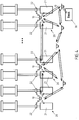
Figur 4 zeigt schematisch den Einsatz mehrerer unbemannter Fahrzeuge zum Datenaustausch mit mehreren Kommunikationspartnern. - Im Folgenden werden bevorzugte Ausführungsbeispiele anhand der Figuren beschrieben. Dabei sind gleiche, ähnliche oder gleichwirkende Elemente mit identischen Bezugszeichen versehen, und auf eine wiederholende Beschreibung dieser Elemente wird teilweise verzichtet, um Redundanzen zu vermeiden.
- Die
Figuren 1A und 1B zeigen schematisch den Einsatz eines unbemannten Fahrzeugs (im Folgenden auch als "UF" bezeichnet) 10 zum Austausch von Informationen mit einem Kommunikationspartner (im Folgenden auch als "KP" bezeichnet) in einer Industrieanlage. Als KP kann etwa eine Maschine, ein Bauteil einer Industrieanlage, eine Komponente usw. in einer Industrieanlage fungieren, die der Einfachheit halber zusammenfassend als "Bauteil" oder "Komponente" bezeichnet und mit dem Bezugszeichen 20 versehen werden. Die Bauteile 20 weisen jeweils eine oder mehrere Sende- und/oder Empfangseinrichtungen 21, 22, 23 auf, um Betriebsdaten mit dem UF 10 auszutauschen. Allerdings können auch andere Einrichtungen Kommunikationspartner für das UF 10 sein, beispielsweise eine Basis 30, weitere UF 10, die weiter unten im Detail beschrieben sind, und/oder mobile Endgeräte, über die ein UF 10 auch mit einem Menschen, etwa einer Bedienperson, kommunizieren kann. - Den Sende- und Empfangseinrichtungen 21, 22, 23 sind jeweils Vorrichtungen (beispielsweise Sensoren mit Datenverarbeitungseinheit) zugeordnet und mit diesen physisch oder drahtlos verbunden, die die so eingerichtet sind, dass sie z. B. Betriebsdaten eigenständig aufzeichnen und gegebenenfalls aufbereiten, etwa digitalisieren, können. Darüber hinaus ist es möglich, dass eine oder mehrere Komponenten 20, insbesondere deren Datenverarbeitungseinheiten, so eingerichtet sind, dass auf diesen Modelle laufen, etwa aus den Betriebsdaten weitere Daten berechnet werden können, beispielsweise ein Modell, das Rückschlüsse auf etwaige Beschädigungen erlaubt.
- Als UF 10 kommen beispielsweise in Frage: fliegende UF, wie etwa Multikopter; sogenannte "Unmanned Aerial Vehicles"; "Micro Aerial Vehicles"; fahrende UF, die freibeweglich oder geführt sind, etwa auf Schienen; schwimmende, tauchende UF; Hybrid-UF usw.
- Um eine störungsfreie Kommunikation zu ermöglichen, begibt sich das UF 10 an einen Übertragungsort in Kommunikationsnähe zur Komponente 20. Zu diesem Zweck kann eine definierte Stelle als Übertragungsort oder ein Bereich vorgegeben sein. Befindet sich das UF 10 am Übertragungsort in der Nähe der Komponente 20, kann das UF 10 mit dieser uni- oder bidirektional Informationen austauschen. Zu diesen Informationen gehören beispielsweise auch ein Zeit-und/oder Ortsstempel und/oder eine Komponenten-ID. Durch die optional bidirektionale Verwendung von Zeit- und/oder Ortsstempeln und/oder einer Komponenten-ID kann vor allem bei einer weiteren Verarbeitung der Daten, z. B. durch ein Prozessleitsystem, sichergestellt werden, dass die Daten dem richtigen Kommunikationspartner, sprich der richtigen Anlagenkomponente zugeordnet werden. Gleichzeitig kann durch die Verwendung von Komponenten-IDs sichergestellt werden, dass nur autorisierte Komponenten miteinander kommunizieren, so dass z. B. die Möglichkeit von Industriespionage zumindest reduziert wird. Die Zeit- und/oder Ortsstempel sowie die Komponenten-ID werden vorzugsweise während der Kommunikation mitprotokolliert, vorteilhafterweise von beiden Kommunikationspartnern, vorzugsweise jedoch vom UF.
- Da die ausgetauschten und mitprotokollierten Daten von einem KP nicht zwangsläufig direkt vom UF an einen weiteren Kommunikationspartner übergeben werden müssen, besitzt das UF eine Vorrichtung zum Speichern der Daten, vorteilhafterweise auch der KP. Damit wird z. B. sichergestellt, dass die Daten auch nach dem Ende der Kommunikation zur Verfügung stehen und beispielsweise in einem späteren Schritt weiterverarbeitet werden können.
- Dazu sind das UF 10 und die Komponente 20 mit aufeinander abgestimmten Sende- und/ Empfangseinheiten 21, 22, 23 ausgestattet, die besonders bevorzugt nur über eine kurze Distanz senden und empfangen, um so die "Funkverschmutzung" sowie den Energieverbrauch der Sende- und Empfangseinrichtungen in der Industrieanlage gering zu halten. Auf diese Weise wird sichergestellt, dass selbst bei einer beabsichtigten oder unbeabsichtigten Verwendung einer bereits belegten Frequenz der übrige Funkverkehr in der Umgebung nicht gestört wird und, umgekehrt, der Funkverkehr in der Umgebung den Datenaustausch nicht stört. Anstatt den Datenaustausch mit einer hohen Übertragungsleistung über eine lange Strecke in der Industrieanlage durchzuführen, begibt sich das UF 10 gezielt in die Umgebung einer Komponente 20, um den Datenaustausch über eine kurze Distanz zu realisieren. Dadurch verringert sich nicht nur die Gefahr einer Funkstörung, sondern ferner können die Übertragungsleistungen verringert werden. Gegebenenfalls kann die Kommunikation auch durch eine physische Verbindung zwischen dem UF 10 und dem KP erfolgen.
- Die Kommunikation zwischen einem UF 10 und den KP ist in den Figuren mittels Pfeilen dargestellt. In den
Figuren 1A und 1B erfolgt die Kommunikation mit einer Komponente 20 mit mehreren Sende- und Empfangseinrichtungen 21, 22 und 23, die etwa mehreren Sensoren zugeordnet sein können. Aus derFigur 2 geht hervor, dass von einem definierten Ort eine Kommunikation auch mit mehreren Komponenten 20 (mit zugehörigen Sende- und Empfangseinrichtungen 21 und 22) erfolgen kann. - Optional kann es sich bei dem definierten Ort um eine Plattform oder Andockstelle 11 handeln, wie es aus der
Figur 1B hervorgeht. Ein fliegendes UF 10 müsste dann während des Datenaustauschs nicht in der Luft schweben, sondern könnte auf der Plattform 11 landen und so beispielsweise den Akku schonen, aufladen oder austauschen. Dazu kann die Plattform 11 mit einer Einrichtung zum Austausch des Akkus oder mit einer Ladeeinrichtung ausgestattet sein. Das Laden des Akkus kann durch eine physische elektrische Verbindung oder drahtlos erfolgen. - Nachdem das UF 10 Informationen von einer oder mehreren Komponenten 20 empfangen hat, kann es sich an einen anderen Ort bewegen, beispielsweise an einen weiteren Übertragungsort zum Austausch von Informationen mit einer oder mehreren weiteren Komponenten 20 oder einer Basis 30, welche die empfangenen Informationen, z. B. zur Überwachung und Steuerung des Produktionsprozesses, weiterverarbeitet. Das "Einsammeln" oder "Verteilen" von Daten von den bzw. an die Komponenten 20 und der Transport an eine Basis 30 gehen aus den
Figuren 3 und4 hervor. - Auf analoge Weise kann das UF 10 so eingerichtet sein, dass es eine Kommunikation zwischen mehreren KP ermöglicht, so dass das UF 10 als "mobiler Repeater" zwischen mehreren KP fungiert, wodurch die KP miteinander Daten austauschen und sich ggf. untereinander abstimmen können. Indem ein UF 10 Daten von einem KP zu einem oder mehreren anderen KP überträgt und so eine Kommunikation zwischen einem oder mehreren KP herstellt, kann insbesondere der Produktionsprozess untereinander abgestimmt werden.
- An der Basis 30 können die gesammelten Daten an weitere Prozesse, beispielsweise an ein Prozessleitsystem übergeben werden. Anschließend kann sich das UF 10 an weitere Übertragungsorte in der Industrieanlage begeben, um erneut Daten mit Kommunikationspartnern auszutauschen. Es sei darauf hingewiesen, dass auch die Basis 30 mit einer Plattform oder Andockstelle ausgerüstet sein kann, wie es oben mit Bezug auf die Plattform/Andockstelle 11 beschrieben ist.
- Gemäß einem bevorzugten Ausführungsbeispiel verfügt das UF 10 über eine stärkere Funkleistung als die Komponente 20, wodurch es aus einer größeren Entfernung (im Vergleich zur Komponente 20) z. B. mit der Basis 30 oder einem mobilen Endgerät kommunizieren kann, ohne dass der übrige Funkverkehr gestört wird. Die Störung des Funkverkehrs ist hierbei ein Aspekt. Ein anderer ist, dass zum Beispiel bei Bluetooth die Übertragungsentfernung sehr begrenzt ist und zusätzlich durch viel Metall in der Industrieanlage beeinträchtigt wird. Zum Austausch mit der Basis 30 kann gemäß einem weiteren Ausführungsbeispiel das UF 10 die gleiche Funkfrequenz wie zum Austausch mit der Komponente 20 nutzen. In diesem Fall fungiert das UF 10 als ein "mobiler Repeater" zur Reichweitenerhöhung. Alternativ können unterschiedliche Frequenzen verwendet werden.
- Neben einer Kommunikation mit Komponenten 20 der Industrieanlage und einer Basis 30 kann das UF 10 auch mit weiteren UF 10 kommunizieren, wie es in der
Figur 4 gezeigt ist. Mehrere als "Schwarm" arrangierte UF 10 können sich zwischen dem ersten KP, beispielsweise einer ersten Komponente 20, und dem letzten KP, beispielsweise der Basis 30, aufhalten. Auf diese Weise können die UF 10 neben den Informationen, die sie mit den benachbarten UF 10 austauschen, optional Informationen mit anderen KP, etwa Komponenten 20, austauschen und diese gegebenenfalls entlang der UF-Kette bis zur Basis 30 weiterleiten. Somit können die UF 10 genutzt werden, um Informationen über eine große Distanz zu transportieren, zu verstärken, zu bündeln, zu verteilen, zu verarbeiten und/oder zu speichern, vorzugsweise temporär, ohne dass der übrige Funkverkehr gestört wird und ohne dass die einzelnen UF 10 große Distanzen zurücklegen müssen, um die Daten der KP 20 einzusammeln oder an die KP 20 zu verteilen. Optional können die UF dazu auch spezielle Plattformen aufsuchen. - Gemäß einem bevorzugten Ausführungsbeispiel sind die UF 10 so eingerichtet, dass sie ihre Funkfrequenzen anpassen können, beispielsweise in Abhängigkeit des betreffenden KP, des Aufenthaltsorts, der Entfernung zum KP, der freien Frequenzen im betreffenden Anlagenbereich, der Datenmenge usw. Diese Anpassung kann für jeden Kommunikationsvorgang individuell erfolgen.
- Soweit anwendbar, können alle einzelnen Merkmale, die in den Ausführungsbeispielen dargestellt sind, miteinander kombiniert und/oder ausgetauscht werden, ohne den Bereich der Erfindung zu verlassen.
-
- 10
- Unbemanntes Fahrzeug (UF)
- 11
- Plattform für das UF am Übertragungsort
- 20
- Komponente/Bauteil einer Industrieanlage
- 21, 22, 23
- Sende-/Empfangseinrichtung von Komponenten/Bauteilen
- 30
- Basis
Claims (16)
- Verfahren zur Datenerfassung in einer Industrieanlage, insbesondere einer hüttentechnischen Anlage, besonders bevorzugt in einem Kalt- oder Warmwalzwerk, einer Bandbehandlungsanlage oder einem Stahlwerk, wobei in der Industrieanlage Daten vorzugsweise drahtlos ausgetauscht werden, wobei das Verfahren aufweist:Bereitstellen wenigstens eines unbemannten Fahrzeugs (10), das eine Sende- und Empfangseinrichtung zur Übermittlung, vorzugsweise drahtlos, und zum Empfang, vorzugsweise drahtlos, von Daten aufweist;Bereitstellen eines oder mehrerer Kommunikationspartner (10, 20, 30), die jeweils eine Sende- und/oder Empfangseinrichtung (21, 22, 23) zur Übermittlung, vorzugsweise drahtlos, und/oder zum Empfang, vorzugsweise drahtlos, von Daten aufweisen; wobeidie Sende- und Empfangseinrichtungen (21, 22, 23) eingerichtet sind, um zwischen dem unbemannten Fahrzeug (10) und dem Kommunikationspartner (10, 20, 30) Daten auszutauschen, und wobei zum Austausch von Daten zwischen dem unbemannten Fahrzeug (10) und dem Kommunikationspartner (10, 20, 30) sich das unbemannte Fahrzeug (10) an einen Übertragungsort in Kommunikationsnähe des Kommunikationspartners (10, 20, 30) begibt, um anschließend den Datenaustausch vorzunehmen.
- Verfahren nach Anspruch 1,
dadurch gekennzeichnet, dass das unbemannte Fahrzeug (10) und/oder der Kommunikationspartner (10, 20, 30) einen Zeit- und/oder Ortsstempel und/oder eine Komponenten-ID austauschen und mitprotokolieren. - Verfahren nach Anspruch 1 oder 2,
dadurch gekennzeichnet, dass wenigstens einer der Kommunikationspartner (10, 20, 30) ein Bauteil (20) einer Industrieanlage ist, das so eingerichtet ist, dass es Betriebsdaten eigenständig aufzeichnen, vorzugsweise verarbeiten und an das am Übertragungsort befindliche unbemannte Fahrzeug (10) übertragen kann. - Verfahren nach Anspruch 3,
dadurch gekennzeichnet, dass das Bauteil (20) eine Rolle, vorzugsweise Arbeitswalze, Stützwalze oder Transportrolle in einem Walzwerk; eine Antriebsvorrichtung, vorzugsweise ein Elektromotor; oder ein Drehlager ist. - Verfahren nach einem der vorigen Ansprüche,
dadurch gekennzeichnet, dass das unbemannte Fahrzeug (10) eine autarke Energiequelle, vorzugsweise einen Akku, für den Betrieb des unbemannten Fahrzeugs (10) aufweist und am Übertragungsort vorzugsweise eine Einrichtung zum automatischen Laden, Nachfüllen und/oder Austausch der Energiequelle vorgesehen ist. - Verfahren nach einem der vorigen Ansprüche,
dadurch gekennzeichnet, dass zum Austausch von Daten zwischen dem unbemannten Fahrzeug (10) und dem Kommunikationspartner (10, 20, 30) sich das unbemannte Fahrzeug (10) und der Kommunikationspartner (10, 20, 30) in physischen Kontakt treten, wobei zu diesem Zweck das unbemannte Fahrzeug (10) und/oder der Kommunikationspartner (10, 20, 30) mit einer oder mehreren Steckverbindungen und/oder Kontaktstellen ausgerüstet sind. - Verfahren nach einem der vorigen Ansprüche,
dadurch gekennzeichnet, dass das unbemannte Fahrzeug (10) ein unbemanntes Luftfahrzeug ist, vorzugsweise ein Multikopter. - Verfahren nach Anspruch 7,
dadurch gekennzeichnet, dass am Übertragungsort eine Landeplattform vorgesehen ist, auf der das unbemannte Luftfahrzeug zum Datenaustausch landet. - Verfahren nach einem der vorigen Ansprüche,
dadurch gekennzeichnet, dass das unbemannte Fahrzeug (10) so eingerichtet ist, dass es von einem Übertragungsort aus mit mehreren Kommunikationspartnern (10, 20, 30) Daten austauschen kann. - Verfahren nach einem der vorigen Ansprüche,
dadurch gekennzeichnet, dass mehrere Kommunikationspartner (10, 20, 30) vorgesehen sind, wobei einer der Kommunikationspartner eine Basis (30) ist, die so eingerichtet ist, dass sie Daten, die sie von dem unbemannten Fahrzeug (10) empfängt, zur Überwachung und/oder Steuerung des Produktionsprozesses der Industrieanlage weiterverarbeiten kann. - Verfahren nach Anspruch 10,
dadurch gekennzeichnet, dass der Datenaustausch zwischen dem unbemannten Fahrzeug (10) und der Basis (30) und zwischen dem unbemannten Fahrzeug (10) und einem oder mehreren weiteren Kommunikationspartnern (10, 20, 30) über denselben Übertragungskanal, vorzugsweise mittels derselben Funkfrequenz erfolgt. - Verfahren nach einem der vorigen Ansprüche,
dadurch gekennzeichnet, dass mehrere Kommunikationspartner (10, 20, 30) vorgesehen sind, wobei zumindest einer der Kommunikationspartner ein weiteres unbemanntes Fahrzeug (10) ist. - Verfahren nach einem der vorigen Ansprüche,
dadurch gekennzeichnet, dass die Sendeleistung des unbemannten Fahrzeugs (10) größer ist, als die des Kommunikationspartners (10, 20, 30). - Verfahren nach einem der vorigen Ansprüche,
dadurch gekennzeichnet, dass das unbemannte Fahrzeug (10) so eingerichtet ist, dass es den Übertragungskanal, vorzugsweise die Funkfrequenz, zum Datenaustausch anpassen kann. - Verfahren nach Anspruch 14,
dadurch gekennzeichnet, dass die Anpassung des Übertragungskanals in Abhängigkeit des Kommunikationspartners (10, 20, 30) und/oder des Aufenthaltsorts des unbemannten Fahrzeugs (10) und/oder der Entfernung des unbemannten Fahrzeugs (10) zum Kommunikationspartner (10, 20, 30) und/oder der freien Übertragungskanäle in der Industrieanlage und/oder der zu übertragenden Datenmenge erfolgt. - System zur Datenerfassung in einer Industrieanlage, insbesondere einer hüttentechnischen Anlage, besonders bevorzugt in einem Kalt- oder Warmwalzwerk, einer Bandbehandlungsanlage oder einem Stahlwerk, wobei in der Industrieanlage Daten vorzugsweise drahtlos ausgetauscht werden, wobei das System aufweist:wenigstens ein unbemanntes Fahrzeug (10), das eine Sende- und Empfangseinrichtung zur Übermittlung, vorzugsweise drahtlos, und zum Empfang, vorzugsweise drahtlos, von Daten aufweist;einen oder mehrere Kommunikationspartner (10, 20, 30), die jeweils eine Sende- und/oder Empfangseinrichtung (21, 22, 23) zur Übermittlung, vorzugsweise drahtlos, und/oder zum Empfang, vorzugsweise drahtlos, von Daten aufweisen; wobeidie Sende- und Empfangseinrichtungen (21, 22, 23) eingerichtet sind, um zwischen dem unbemannten Fahrzeug (10) und dem Kommunikationspartner (10, 20, 30) Daten auszutauschen, und wobei das System eingerichtet ist, um ein Verfahren nach einem der vorigen Ansprüche durchzuführen.
Applications Claiming Priority (1)
| Application Number | Priority Date | Filing Date | Title |
|---|---|---|---|
| DE102016223438.2A DE102016223438A1 (de) | 2016-11-25 | 2016-11-25 | Unbemannte Fahrzeuge zur Datenerfassung in Industrieanlagen |
Publications (2)
| Publication Number | Publication Date |
|---|---|
| EP3327527A1 true EP3327527A1 (de) | 2018-05-30 |
| EP3327527B1 EP3327527B1 (de) | 2019-05-29 |
Family
ID=60327098
Family Applications (1)
| Application Number | Title | Priority Date | Filing Date |
|---|---|---|---|
| EP17201131.4A Active EP3327527B1 (de) | 2016-11-25 | 2017-11-10 | Unbemannte fahrzeuge zur datenerfassung in industrieanlagen |
Country Status (2)
| Country | Link |
|---|---|
| EP (1) | EP3327527B1 (de) |
| DE (1) | DE102016223438A1 (de) |
Cited By (6)
| Publication number | Priority date | Publication date | Assignee | Title |
|---|---|---|---|---|
| US11486472B2 (en) | 2020-04-16 | 2022-11-01 | United Technologies Advanced Projects Inc. | Gear sytems with variable speed drive |
| US11535392B2 (en) | 2019-03-18 | 2022-12-27 | Pratt & Whitney Canada Corp. | Architectures for hybrid-electric propulsion |
| US11628942B2 (en) | 2019-03-01 | 2023-04-18 | Pratt & Whitney Canada Corp. | Torque ripple control for an aircraft power train |
| US11697505B2 (en) | 2019-03-01 | 2023-07-11 | Pratt & Whitney Canada Corp. | Distributed propulsion configurations for aircraft having mixed drive systems |
| US11732639B2 (en) | 2019-03-01 | 2023-08-22 | Pratt & Whitney Canada Corp. | Mechanical disconnects for parallel power lanes in hybrid electric propulsion systems |
| US12240619B2 (en) | 2019-03-01 | 2025-03-04 | Pratt & Whitney Canada Corp. | Torque balancing for hybrid electric propulsion systems and aircraft utilizing hybrid electric propulsion systems |
Citations (2)
| Publication number | Priority date | Publication date | Assignee | Title |
|---|---|---|---|---|
| WO2007021425A1 (en) | 2005-08-17 | 2007-02-22 | Xtek, Inc. | Data acquisition system for system monitoring |
| US20140024313A1 (en) * | 2012-07-20 | 2014-01-23 | Green Badge LLC | Data Collection Network For Agriculture And Other Applications |
-
2016
- 2016-11-25 DE DE102016223438.2A patent/DE102016223438A1/de not_active Withdrawn
-
2017
- 2017-11-10 EP EP17201131.4A patent/EP3327527B1/de active Active
Patent Citations (2)
| Publication number | Priority date | Publication date | Assignee | Title |
|---|---|---|---|---|
| WO2007021425A1 (en) | 2005-08-17 | 2007-02-22 | Xtek, Inc. | Data acquisition system for system monitoring |
| US20140024313A1 (en) * | 2012-07-20 | 2014-01-23 | Green Badge LLC | Data Collection Network For Agriculture And Other Applications |
Cited By (8)
| Publication number | Priority date | Publication date | Assignee | Title |
|---|---|---|---|---|
| US11628942B2 (en) | 2019-03-01 | 2023-04-18 | Pratt & Whitney Canada Corp. | Torque ripple control for an aircraft power train |
| US11697505B2 (en) | 2019-03-01 | 2023-07-11 | Pratt & Whitney Canada Corp. | Distributed propulsion configurations for aircraft having mixed drive systems |
| US11732639B2 (en) | 2019-03-01 | 2023-08-22 | Pratt & Whitney Canada Corp. | Mechanical disconnects for parallel power lanes in hybrid electric propulsion systems |
| US12240619B2 (en) | 2019-03-01 | 2025-03-04 | Pratt & Whitney Canada Corp. | Torque balancing for hybrid electric propulsion systems and aircraft utilizing hybrid electric propulsion systems |
| US11535392B2 (en) | 2019-03-18 | 2022-12-27 | Pratt & Whitney Canada Corp. | Architectures for hybrid-electric propulsion |
| US12071256B2 (en) | 2019-03-18 | 2024-08-27 | Pratt & Whitney Canada Corp. | Architectures for hybrid-electric propulsion |
| US11486472B2 (en) | 2020-04-16 | 2022-11-01 | United Technologies Advanced Projects Inc. | Gear sytems with variable speed drive |
| US12066083B2 (en) | 2020-04-16 | 2024-08-20 | Pratt & Whitney Canada Corp. | Gear systems with variable speed drive |
Also Published As
| Publication number | Publication date |
|---|---|
| EP3327527B1 (de) | 2019-05-29 |
| DE102016223438A1 (de) | 2018-05-30 |
Similar Documents
| Publication | Publication Date | Title |
|---|---|---|
| EP3327526B1 (de) | Unbemannte fahrzeuge zur prozessüberwachung in industrieanlagen | |
| EP3327527B1 (de) | Unbemannte fahrzeuge zur datenerfassung in industrieanlagen | |
| DE102016124798B4 (de) | Fertigungssystem, in dem ein werkstück transferiert wird | |
| EP2218624B1 (de) | Radsensor, Eisenbahnanlage mit zumindest einem Radsensor sowie Verfahren zum Betreiben einer Eisenbahnanlage | |
| EP3467601A2 (de) | Sicherheitssystem zur absicherung eines kooperativen betriebs von menschen, robotern und maschinen | |
| EP2629899A1 (de) | Transportsystem, transportwagen und verfahren zum transport von metallbunde | |
| DE102015205032A1 (de) | Fahrzeugverbund und Verfahren zum Bilden und Betreiben eines Fahrzeugverbundes | |
| DE102016014034A1 (de) | Mobiles Laden einer Fahrzeugbatterie eines Elektrofahrzeuges | |
| DE102012202540A1 (de) | Diagnoseverfahren und Diagnosevorrichtung für eine Fahrzeugkomponente eines Fahrzeugs | |
| EP2531391A1 (de) | Verfahren und vorrichtung zur überwachung der zugvollständigkeit | |
| EP3416401A1 (de) | Mobiles transportmittel zum transportieren von datensammlern, datensammelsystem und datensammelverfahren | |
| DE102011109532A1 (de) | Anlage und Verfahren zum Betreiben einer Anlage | |
| EP3198042B1 (de) | Metallindustrieanlage und verfahren zur verfolgung eines gefässes, insbesondere eines metallurgischen gefässes | |
| EP1455976B1 (de) | Maulweitenregelung an segmenten für stranggie anlagen | |
| DE102017119686B4 (de) | System zur Überwachung, Exploration und Inspektion mittels Drohnen | |
| EP3663011A1 (de) | Erfassen und übertragen von daten eines lagers eines stahl- oder walzwerks | |
| WO2022073563A1 (de) | Verfahren zur inspektion einer anlage, vorzugsweise einer förderanlage | |
| DE102013113069B4 (de) | Drahtloskommunikation im untertägigen Bergbau | |
| DE102008047755A1 (de) | Vorrichtung und Verfahren zur Steuerung von Elektrohängebahnen | |
| WO2023247078A1 (de) | Stationsnetzwerk für autonome und/oder teilautonome unbemannte luftfahrzeuge sowie verfahren zur steuerung von autonomen oder teilautonomen unbemannten luftfahrzeugen | |
| DE102016209402B4 (de) | Vorrichtung und Verfahren zur Überwachung eines mobilen Objekts | |
| DE202016004168U1 (de) | Gebäudetechnikvorrichtung und Leuchte, System für deren Instandhaltung mittels einer mobilen Vorrichtung und mobile Vorrichtung | |
| DE102019218046A1 (de) | Satellitengestützte Verfolgung von metallurgischen Gefäßen in einer Metallindustrieanlage | |
| DE102011075855A1 (de) | Vorrichtung und Verfahren zur Kontrolle einer hüttenmännischen Anlage | |
| CH721410A1 (de) | Inspektionswagen für eine förderanlage und förderanlage |
Legal Events
| Date | Code | Title | Description |
|---|---|---|---|
| PUAI | Public reference made under article 153(3) epc to a published international application that has entered the european phase |
Free format text: ORIGINAL CODE: 0009012 |
|
| STAA | Information on the status of an ep patent application or granted ep patent |
Free format text: STATUS: REQUEST FOR EXAMINATION WAS MADE |
|
| STAA | Information on the status of an ep patent application or granted ep patent |
Free format text: STATUS: EXAMINATION IS IN PROGRESS |
|
| 17P | Request for examination filed |
Effective date: 20171110 |
|
| AK | Designated contracting states |
Kind code of ref document: A1 Designated state(s): AL AT BE BG CH CY CZ DE DK EE ES FI FR GB GR HR HU IE IS IT LI LT LU LV MC MK MT NL NO PL PT RO RS SE SI SK SM TR |
|
| AX | Request for extension of the european patent |
Extension state: BA ME |
|
| 17Q | First examination report despatched |
Effective date: 20180504 |
|
| RBV | Designated contracting states (corrected) |
Designated state(s): AL AT BE BG CH CY CZ DE DK EE ES FI FR GB GR HR HU IE IS IT LI LT LU LV MC MK MT NL NO PL PT RO RS SE SI SK SM TR |
|
| GRAP | Despatch of communication of intention to grant a patent |
Free format text: ORIGINAL CODE: EPIDOSNIGR1 |
|
| STAA | Information on the status of an ep patent application or granted ep patent |
Free format text: STATUS: GRANT OF PATENT IS INTENDED |
|
| RIC1 | Information provided on ipc code assigned before grant |
Ipc: H04W 4/80 20180101ALI20181217BHEP Ipc: H04W 4/40 20180101ALI20181217BHEP Ipc: G05B 19/418 20060101AFI20181217BHEP Ipc: H04W 4/38 20180101ALI20181217BHEP Ipc: H04L 29/08 20060101ALN20181217BHEP |
|
| INTG | Intention to grant announced |
Effective date: 20190111 |
|
| GRAS | Grant fee paid |
Free format text: ORIGINAL CODE: EPIDOSNIGR3 |
|
| GRAA | (expected) grant |
Free format text: ORIGINAL CODE: 0009210 |
|
| STAA | Information on the status of an ep patent application or granted ep patent |
Free format text: STATUS: THE PATENT HAS BEEN GRANTED |
|
| AK | Designated contracting states |
Kind code of ref document: B1 Designated state(s): AL AT BE BG CH CY CZ DE DK EE ES FI FR GB GR HR HU IE IS IT LI LT LU LV MC MK MT NL NO PL PT RO RS SE SI SK SM TR |
|
| REG | Reference to a national code |
Ref country code: GB Ref legal event code: FG4D Free format text: NOT ENGLISH |
|
| REG | Reference to a national code |
Ref country code: CH Ref legal event code: EP |
|
| REG | Reference to a national code |
Ref country code: DE Ref legal event code: R096 Ref document number: 502017001441 Country of ref document: DE |
|
| REG | Reference to a national code |
Ref country code: AT Ref legal event code: REF Ref document number: 1138651 Country of ref document: AT Kind code of ref document: T Effective date: 20190615 |
|
| REG | Reference to a national code |
Ref country code: IE Ref legal event code: FG4D Free format text: LANGUAGE OF EP DOCUMENT: GERMAN |
|
| REG | Reference to a national code |
Ref country code: NL Ref legal event code: MP Effective date: 20190529 |
|
| REG | Reference to a national code |
Ref country code: LT Ref legal event code: MG4D |
|
| PG25 | Lapsed in a contracting state [announced via postgrant information from national office to epo] |
Ref country code: LT Free format text: LAPSE BECAUSE OF FAILURE TO SUBMIT A TRANSLATION OF THE DESCRIPTION OR TO PAY THE FEE WITHIN THE PRESCRIBED TIME-LIMIT Effective date: 20190529 Ref country code: HR Free format text: LAPSE BECAUSE OF FAILURE TO SUBMIT A TRANSLATION OF THE DESCRIPTION OR TO PAY THE FEE WITHIN THE PRESCRIBED TIME-LIMIT Effective date: 20190529 Ref country code: FI Free format text: LAPSE BECAUSE OF FAILURE TO SUBMIT A TRANSLATION OF THE DESCRIPTION OR TO PAY THE FEE WITHIN THE PRESCRIBED TIME-LIMIT Effective date: 20190529 Ref country code: NO Free format text: LAPSE BECAUSE OF FAILURE TO SUBMIT A TRANSLATION OF THE DESCRIPTION OR TO PAY THE FEE WITHIN THE PRESCRIBED TIME-LIMIT Effective date: 20190829 Ref country code: SE Free format text: LAPSE BECAUSE OF FAILURE TO SUBMIT A TRANSLATION OF THE DESCRIPTION OR TO PAY THE FEE WITHIN THE PRESCRIBED TIME-LIMIT Effective date: 20190529 Ref country code: AL Free format text: LAPSE BECAUSE OF FAILURE TO SUBMIT A TRANSLATION OF THE DESCRIPTION OR TO PAY THE FEE WITHIN THE PRESCRIBED TIME-LIMIT Effective date: 20190529 Ref country code: PT Free format text: LAPSE BECAUSE OF FAILURE TO SUBMIT A TRANSLATION OF THE DESCRIPTION OR TO PAY THE FEE WITHIN THE PRESCRIBED TIME-LIMIT Effective date: 20190930 Ref country code: ES Free format text: LAPSE BECAUSE OF FAILURE TO SUBMIT A TRANSLATION OF THE DESCRIPTION OR TO PAY THE FEE WITHIN THE PRESCRIBED TIME-LIMIT Effective date: 20190529 |
|
| PG25 | Lapsed in a contracting state [announced via postgrant information from national office to epo] |
Ref country code: GR Free format text: LAPSE BECAUSE OF FAILURE TO SUBMIT A TRANSLATION OF THE DESCRIPTION OR TO PAY THE FEE WITHIN THE PRESCRIBED TIME-LIMIT Effective date: 20190830 Ref country code: BG Free format text: LAPSE BECAUSE OF FAILURE TO SUBMIT A TRANSLATION OF THE DESCRIPTION OR TO PAY THE FEE WITHIN THE PRESCRIBED TIME-LIMIT Effective date: 20190829 Ref country code: LV Free format text: LAPSE BECAUSE OF FAILURE TO SUBMIT A TRANSLATION OF THE DESCRIPTION OR TO PAY THE FEE WITHIN THE PRESCRIBED TIME-LIMIT Effective date: 20190529 Ref country code: RS Free format text: LAPSE BECAUSE OF FAILURE TO SUBMIT A TRANSLATION OF THE DESCRIPTION OR TO PAY THE FEE WITHIN THE PRESCRIBED TIME-LIMIT Effective date: 20190529 |
|
| PG25 | Lapsed in a contracting state [announced via postgrant information from national office to epo] |
Ref country code: EE Free format text: LAPSE BECAUSE OF FAILURE TO SUBMIT A TRANSLATION OF THE DESCRIPTION OR TO PAY THE FEE WITHIN THE PRESCRIBED TIME-LIMIT Effective date: 20190529 Ref country code: SK Free format text: LAPSE BECAUSE OF FAILURE TO SUBMIT A TRANSLATION OF THE DESCRIPTION OR TO PAY THE FEE WITHIN THE PRESCRIBED TIME-LIMIT Effective date: 20190529 Ref country code: DK Free format text: LAPSE BECAUSE OF FAILURE TO SUBMIT A TRANSLATION OF THE DESCRIPTION OR TO PAY THE FEE WITHIN THE PRESCRIBED TIME-LIMIT Effective date: 20190529 Ref country code: NL Free format text: LAPSE BECAUSE OF FAILURE TO SUBMIT A TRANSLATION OF THE DESCRIPTION OR TO PAY THE FEE WITHIN THE PRESCRIBED TIME-LIMIT Effective date: 20190529 Ref country code: RO Free format text: LAPSE BECAUSE OF FAILURE TO SUBMIT A TRANSLATION OF THE DESCRIPTION OR TO PAY THE FEE WITHIN THE PRESCRIBED TIME-LIMIT Effective date: 20190529 Ref country code: CZ Free format text: LAPSE BECAUSE OF FAILURE TO SUBMIT A TRANSLATION OF THE DESCRIPTION OR TO PAY THE FEE WITHIN THE PRESCRIBED TIME-LIMIT Effective date: 20190529 |
|
| PG25 | Lapsed in a contracting state [announced via postgrant information from national office to epo] |
Ref country code: SM Free format text: LAPSE BECAUSE OF FAILURE TO SUBMIT A TRANSLATION OF THE DESCRIPTION OR TO PAY THE FEE WITHIN THE PRESCRIBED TIME-LIMIT Effective date: 20190529 |
|
| REG | Reference to a national code |
Ref country code: DE Ref legal event code: R097 Ref document number: 502017001441 Country of ref document: DE |
|
| PG25 | Lapsed in a contracting state [announced via postgrant information from national office to epo] |
Ref country code: TR Free format text: LAPSE BECAUSE OF FAILURE TO SUBMIT A TRANSLATION OF THE DESCRIPTION OR TO PAY THE FEE WITHIN THE PRESCRIBED TIME-LIMIT Effective date: 20190529 |
|
| PLBE | No opposition filed within time limit |
Free format text: ORIGINAL CODE: 0009261 |
|
| STAA | Information on the status of an ep patent application or granted ep patent |
Free format text: STATUS: NO OPPOSITION FILED WITHIN TIME LIMIT |
|
| PG25 | Lapsed in a contracting state [announced via postgrant information from national office to epo] |
Ref country code: PL Free format text: LAPSE BECAUSE OF FAILURE TO SUBMIT A TRANSLATION OF THE DESCRIPTION OR TO PAY THE FEE WITHIN THE PRESCRIBED TIME-LIMIT Effective date: 20190529 |
|
| 26N | No opposition filed |
Effective date: 20200303 |
|
| PG25 | Lapsed in a contracting state [announced via postgrant information from national office to epo] |
Ref country code: SI Free format text: LAPSE BECAUSE OF FAILURE TO SUBMIT A TRANSLATION OF THE DESCRIPTION OR TO PAY THE FEE WITHIN THE PRESCRIBED TIME-LIMIT Effective date: 20190529 |
|
| PG25 | Lapsed in a contracting state [announced via postgrant information from national office to epo] |
Ref country code: MC Free format text: LAPSE BECAUSE OF FAILURE TO SUBMIT A TRANSLATION OF THE DESCRIPTION OR TO PAY THE FEE WITHIN THE PRESCRIBED TIME-LIMIT Effective date: 20190529 Ref country code: LU Free format text: LAPSE BECAUSE OF NON-PAYMENT OF DUE FEES Effective date: 20191110 |
|
| REG | Reference to a national code |
Ref country code: BE Ref legal event code: MM Effective date: 20191130 |
|
| PG25 | Lapsed in a contracting state [announced via postgrant information from national office to epo] |
Ref country code: FR Free format text: LAPSE BECAUSE OF NON-PAYMENT OF DUE FEES Effective date: 20191130 Ref country code: IE Free format text: LAPSE BECAUSE OF NON-PAYMENT OF DUE FEES Effective date: 20191110 |
|
| PG25 | Lapsed in a contracting state [announced via postgrant information from national office to epo] |
Ref country code: BE Free format text: LAPSE BECAUSE OF NON-PAYMENT OF DUE FEES Effective date: 20191130 |
|
| PG25 | Lapsed in a contracting state [announced via postgrant information from national office to epo] |
Ref country code: CY Free format text: LAPSE BECAUSE OF FAILURE TO SUBMIT A TRANSLATION OF THE DESCRIPTION OR TO PAY THE FEE WITHIN THE PRESCRIBED TIME-LIMIT Effective date: 20190529 |
|
| PG25 | Lapsed in a contracting state [announced via postgrant information from national office to epo] |
Ref country code: IS Free format text: LAPSE BECAUSE OF FAILURE TO SUBMIT A TRANSLATION OF THE DESCRIPTION OR TO PAY THE FEE WITHIN THE PRESCRIBED TIME-LIMIT Effective date: 20190929 |
|
| REG | Reference to a national code |
Ref country code: CH Ref legal event code: PL |
|
| PG25 | Lapsed in a contracting state [announced via postgrant information from national office to epo] |
Ref country code: HU Free format text: LAPSE BECAUSE OF FAILURE TO SUBMIT A TRANSLATION OF THE DESCRIPTION OR TO PAY THE FEE WITHIN THE PRESCRIBED TIME-LIMIT; INVALID AB INITIO Effective date: 20171110 Ref country code: MT Free format text: LAPSE BECAUSE OF FAILURE TO SUBMIT A TRANSLATION OF THE DESCRIPTION OR TO PAY THE FEE WITHIN THE PRESCRIBED TIME-LIMIT Effective date: 20190529 |
|
| PG25 | Lapsed in a contracting state [announced via postgrant information from national office to epo] |
Ref country code: LI Free format text: LAPSE BECAUSE OF NON-PAYMENT OF DUE FEES Effective date: 20201130 Ref country code: CH Free format text: LAPSE BECAUSE OF NON-PAYMENT OF DUE FEES Effective date: 20201130 |
|
| PG25 | Lapsed in a contracting state [announced via postgrant information from national office to epo] |
Ref country code: MK Free format text: LAPSE BECAUSE OF FAILURE TO SUBMIT A TRANSLATION OF THE DESCRIPTION OR TO PAY THE FEE WITHIN THE PRESCRIBED TIME-LIMIT Effective date: 20190529 |
|
| GBPC | Gb: european patent ceased through non-payment of renewal fee |
Effective date: 20211110 |
|
| PG25 | Lapsed in a contracting state [announced via postgrant information from national office to epo] |
Ref country code: GB Free format text: LAPSE BECAUSE OF NON-PAYMENT OF DUE FEES Effective date: 20211110 |
|
| P01 | Opt-out of the competence of the unified patent court (upc) registered |
Effective date: 20230707 |
|
| PGFP | Annual fee paid to national office [announced via postgrant information from national office to epo] |
Ref country code: DE Payment date: 20251119 Year of fee payment: 9 |
|
| PGFP | Annual fee paid to national office [announced via postgrant information from national office to epo] |
Ref country code: AT Payment date: 20251120 Year of fee payment: 9 |
|
| PGFP | Annual fee paid to national office [announced via postgrant information from national office to epo] |
Ref country code: IT Payment date: 20251125 Year of fee payment: 9 |