EP3327632B1 - Emballage pour produit pharmaceutique comprenant une étiquette électronique miniaturisée permettant de surveiller l'intégrité du produit - Google Patents
Emballage pour produit pharmaceutique comprenant une étiquette électronique miniaturisée permettant de surveiller l'intégrité du produit Download PDFInfo
- Publication number
- EP3327632B1 EP3327632B1 EP17206676.3A EP17206676A EP3327632B1 EP 3327632 B1 EP3327632 B1 EP 3327632B1 EP 17206676 A EP17206676 A EP 17206676A EP 3327632 B1 EP3327632 B1 EP 3327632B1
- Authority
- EP
- European Patent Office
- Prior art keywords
- tag
- product
- box
- switch
- retail
- Prior art date
- Legal status (The legal status is an assumption and is not a legal conclusion. Google has not performed a legal analysis and makes no representation as to the accuracy of the status listed.)
- Active
Links
Images

Classifications
-
- A—HUMAN NECESSITIES
- A61—MEDICAL OR VETERINARY SCIENCE; HYGIENE
- A61J—CONTAINERS SPECIALLY ADAPTED FOR MEDICAL OR PHARMACEUTICAL PURPOSES; DEVICES OR METHODS SPECIALLY ADAPTED FOR BRINGING PHARMACEUTICAL PRODUCTS INTO PARTICULAR PHYSICAL OR ADMINISTERING FORMS; DEVICES FOR ADMINISTERING FOOD OR MEDICINES ORALLY; BABY COMFORTERS; DEVICES FOR RECEIVING SPITTLE
- A61J1/00—Containers specially adapted for medical or pharmaceutical purposes
- A61J1/14—Details; Accessories therefor
- A61J1/18—Arrangements for indicating condition of container contents, e.g. sterile condition
-
- G—PHYSICS
- G06—COMPUTING OR CALCULATING; COUNTING
- G06K—GRAPHICAL DATA READING; PRESENTATION OF DATA; RECORD CARRIERS; HANDLING RECORD CARRIERS
- G06K19/00—Record carriers for use with machines and with at least a part designed to carry digital markings
- G06K19/06—Record carriers for use with machines and with at least a part designed to carry digital markings characterised by the kind of the digital marking, e.g. shape, nature, code
- G06K19/067—Record carriers with conductive marks, printed circuits or semiconductor circuit elements, e.g. credit or identity cards also with resonating or responding marks without active components
- G06K19/07—Record carriers with conductive marks, printed circuits or semiconductor circuit elements, e.g. credit or identity cards also with resonating or responding marks without active components with integrated circuit chips
- G06K19/0716—Record carriers with conductive marks, printed circuits or semiconductor circuit elements, e.g. credit or identity cards also with resonating or responding marks without active components with integrated circuit chips at least one of the integrated circuit chips comprising a sensor or an interface to a sensor
- G06K19/0717—Record carriers with conductive marks, printed circuits or semiconductor circuit elements, e.g. credit or identity cards also with resonating or responding marks without active components with integrated circuit chips at least one of the integrated circuit chips comprising a sensor or an interface to a sensor the sensor being capable of sensing environmental conditions such as temperature history or pressure
-
- G—PHYSICS
- G06—COMPUTING OR CALCULATING; COUNTING
- G06K—GRAPHICAL DATA READING; PRESENTATION OF DATA; RECORD CARRIERS; HANDLING RECORD CARRIERS
- G06K19/00—Record carriers for use with machines and with at least a part designed to carry digital markings
- G06K19/06—Record carriers for use with machines and with at least a part designed to carry digital markings characterised by the kind of the digital marking, e.g. shape, nature, code
- G06K19/067—Record carriers with conductive marks, printed circuits or semiconductor circuit elements, e.g. credit or identity cards also with resonating or responding marks without active components
- G06K19/07—Record carriers with conductive marks, printed circuits or semiconductor circuit elements, e.g. credit or identity cards also with resonating or responding marks without active components with integrated circuit chips
- G06K19/077—Constructional details, e.g. mounting of circuits in the carrier
- G06K19/07701—Constructional details, e.g. mounting of circuits in the carrier the record carrier comprising an interface suitable for human interaction
-
- G—PHYSICS
- G06—COMPUTING OR CALCULATING; COUNTING
- G06K—GRAPHICAL DATA READING; PRESENTATION OF DATA; RECORD CARRIERS; HANDLING RECORD CARRIERS
- G06K19/00—Record carriers for use with machines and with at least a part designed to carry digital markings
- G06K19/06—Record carriers for use with machines and with at least a part designed to carry digital markings characterised by the kind of the digital marking, e.g. shape, nature, code
- G06K19/067—Record carriers with conductive marks, printed circuits or semiconductor circuit elements, e.g. credit or identity cards also with resonating or responding marks without active components
- G06K19/07—Record carriers with conductive marks, printed circuits or semiconductor circuit elements, e.g. credit or identity cards also with resonating or responding marks without active components with integrated circuit chips
- G06K19/077—Constructional details, e.g. mounting of circuits in the carrier
- G06K19/07701—Constructional details, e.g. mounting of circuits in the carrier the record carrier comprising an interface suitable for human interaction
- G06K19/07709—Constructional details, e.g. mounting of circuits in the carrier the record carrier comprising an interface suitable for human interaction the interface being a keyboard
-
- G—PHYSICS
- G06—COMPUTING OR CALCULATING; COUNTING
- G06K—GRAPHICAL DATA READING; PRESENTATION OF DATA; RECORD CARRIERS; HANDLING RECORD CARRIERS
- G06K19/00—Record carriers for use with machines and with at least a part designed to carry digital markings
- G06K19/06—Record carriers for use with machines and with at least a part designed to carry digital markings characterised by the kind of the digital marking, e.g. shape, nature, code
- G06K19/067—Record carriers with conductive marks, printed circuits or semiconductor circuit elements, e.g. credit or identity cards also with resonating or responding marks without active components
- G06K19/07—Record carriers with conductive marks, printed circuits or semiconductor circuit elements, e.g. credit or identity cards also with resonating or responding marks without active components with integrated circuit chips
- G06K19/077—Constructional details, e.g. mounting of circuits in the carrier
- G06K19/07749—Constructional details, e.g. mounting of circuits in the carrier the record carrier being capable of non-contact communication, e.g. constructional details of the antenna of a non-contact smart card
- G06K19/07798—Constructional details, e.g. mounting of circuits in the carrier the record carrier being capable of non-contact communication, e.g. constructional details of the antenna of a non-contact smart card part of the antenna or the integrated circuit being adapted for rupturing or breaking, e.g. record carriers functioning as sealing devices for detecting not-authenticated opening of containers
-
- A—HUMAN NECESSITIES
- A61—MEDICAL OR VETERINARY SCIENCE; HYGIENE
- A61J—CONTAINERS SPECIALLY ADAPTED FOR MEDICAL OR PHARMACEUTICAL PURPOSES; DEVICES OR METHODS SPECIALLY ADAPTED FOR BRINGING PHARMACEUTICAL PRODUCTS INTO PARTICULAR PHYSICAL OR ADMINISTERING FORMS; DEVICES FOR ADMINISTERING FOOD OR MEDICINES ORALLY; BABY COMFORTERS; DEVICES FOR RECEIVING SPITTLE
- A61J1/00—Containers specially adapted for medical or pharmaceutical purposes
- A61J1/03—Containers specially adapted for medical or pharmaceutical purposes for pills or tablets
- A61J1/035—Blister-type containers
-
- A—HUMAN NECESSITIES
- A61—MEDICAL OR VETERINARY SCIENCE; HYGIENE
- A61J—CONTAINERS SPECIALLY ADAPTED FOR MEDICAL OR PHARMACEUTICAL PURPOSES; DEVICES OR METHODS SPECIALLY ADAPTED FOR BRINGING PHARMACEUTICAL PRODUCTS INTO PARTICULAR PHYSICAL OR ADMINISTERING FORMS; DEVICES FOR ADMINISTERING FOOD OR MEDICINES ORALLY; BABY COMFORTERS; DEVICES FOR RECEIVING SPITTLE
- A61J2205/00—General identification or selection means
- A61J2205/60—General identification or selection means using magnetic or electronic identifications, e.g. chips, RFID, electronic tags
Definitions
- the invention relates to the field of monitoring the integrity of pharmaceutical products which are sensitive to physical or environmental conditions. More generally, it relates to the monitoring of the integrity of perishable products. More particularly, the invention relates to ways of estimating the integrity of a pharmaceutical product as assessed from the exposure of the product to physical or environmental conditions up to at least approximately the time of its use.
- the invention relates to methods and apparatuses according to the opening clauses of the claims.
- Such articles or devices find application, e.g., when a patient taking a medicament or a health care specialist giving the medicament to the patients wants to make sure that the medicament has not perished, in particular not perished during the time span between packaging the medicament and applying the medicament.
- RFID tags are frequently used by transport and logistics companies for monitoring the integrity of various goods during their transport from the manufacturer of the goods to a distributor or wholesaler.
- RFID tags are, e.g., attached to a trading unit on a palette, and results of measurements carried out in the RFID tag, e.g., temperature measurements, are wirelessly transmitted to the RFID reader in order to be evalutated and/or looked at then.
- RFID tags are known, for example, from US 2007/0273507 A1 . There, it is disclosed to combine digital sensing and RFID technology for input and output of sensing data. A sensor can be included for monitoring time and temperature of a perishable item and for determining a current freshness status based on the time and temperature. In said US 2007/0273507 A1 , it is also suggested to add an alternate visual and/or audio communication interface to RF digital sensors for the purpose of communicating shelf-life and sensor data, e.g., via a visual display. In one embodiment, the tag includes a conventional switch for activating (turning on) the visual display, for example, by manually depressing the switch.
- an RFID tag for provision on the package of a perishable product, such as a foodstuff, is known, wherein the expiration of the product being influenced by opening of the package.
- the tag is arranged to determine by means of an opening detector when the package has been opened, e.g., with a rip strip as an opening detector.
- One object of the invention is to create a new way of enabling a person (finally) using a perishable product such as a pharmaceutical product, to check whether or not the product is - with a high probability - sound (flawless), in particular at (approximately) the time of using it.
- Another object of the invention is to provide a simple way of enabling a person to check the integrity of a perishable product, in particular approximately at the time of its use.
- Another object of the invention is to provide a cost-efficient way of enabling a person to check the integrity of a perishable product, in particular approximately at the time of its use.
- Another object of the invention is to provide a way of enabling a person to check the integrity of a perishable product, in particular approximately at the time of its use, which is compatible with already established packaging and distribution schemes.
- Another object of the invention is to provide a way of enabling a person to check the integrity of a perishable product without requiring the presence of any additional object for doing so, e.g., without a reading device.
- Another object of the invention is to provide a way of minimizing the probability of fraud or deceit when it comes to prove or demonstrate an integrity status of a perishable, in particular pharmaceutical, product approximately at the time of its use.
- Another object of the invention is to provide ways for preventing or reducing malpractice in conjunction with monitoring the integrity of sensitive products.
- a corresponding retail package and a corresponding retail unit shall be provided, as well as an unclaimed method for monitoring an integrity of a perishable product.
- an electronic tag for obtaining information relating to the integrity of a product as assessed from an exposure of said product to physical or environmental conditions during a time span shall be provided and a method for manufacturing a retail unit.
- the retail package for a perishable product comprises
- Said electronics unit comprises
- control unit is structured and configured for
- Such a retail package can be very compact and cost-efficient. And it can make possible that a user who wants to use or apply the product (who usually is not a person trading it or dealing with it), such as, in case of a medical product, a patient or a health care specialist, can in a simple and direct way and without further education and without needing further equipment or tools operate the tag and find out about the integrity of the product, in particular at (approximately) the time of using or applying the product.
- the term "retail package” is used in order to distinguish the package from wholesale packages or bundles.
- the latter comprise high numbers of retail packages and do not reach a user of the product.
- the retail package usually is the lowest package level to be sold (under normal circumstances). Inside said box, there is usually no further box present, in particular not a (further) cardboard box, more particularly not a (further) folding carton.
- the product usually is contained in a container, the container being inside the box.
- the box usually also contains a package insert, which usually is one piece of paper explaining details concerning the product, such as its composition, its effects and adverse reactions and dosage instructions.
- a retail package may contain one or more doses of the product. And it may be a package for patients or for clinics.
- Said time span usually is a time span during which said product is stored or transported.
- Said display switch usually is a user-operable switch.
- Suitable switches can be, e.g., electro-mechanical switches or capacitive switches.
- said electrical connection is broken, e.g., because one or more conductor lines (in particular a conductor line loop) of the rip strip is interrupted.
- This can be detected by the control unit, e.g., by sensing an increase of an ohmic resistance. In an unclaimed embodiment, it may be an indication of an end of said time span, and thus, the monitoring can be terminated in reaction thereto.
- the rip strip usually is a flat member (its extension in a first dimension being clearly smaller than in the other two) and has an elongated shape (its extension in a second dimension being smaller than in the third dimension). Said breaking said electrical connection usually takes place by dividing (cutting, tearing apart) the rip strip generally along said second dimension.
- Said display usually is a visual display.
- Said displaying said status data in reaction to an operation of said switch is effected at least after the end of said time span. This can make possible to review the integrity status the product had when the box was opened and/or when the product was accessed and/or when the product was applied. It may, however be provided that said displaying said status data in reaction to an operation of said switch is also effected already before the end of said time span. This can make possible early checks of the product integrity.
- said display does usually not permanently display the status data. This saves energy and thus makes possible a long operation duration of the tag and thus a long shelf life of the retail package and of the retail unit.
- displaying said status data takes place only in reaction to operating said switch. However, it may also be provided that it takes place also in reaction to terminating said monitoring and thus at the end of said time span and thus usually when said terminating switch is operated. And additionally thereto, it may be provided that displaying said status data takes place periodically, e.g., in regular time intervals, the (pause) interval typically being between 1 second and 2 minutes, in particular between 5 seconds and 30 seconds. Such an "automatic" display of the status data may take place after the end of said time span only or during said time span only or both, i.e. from the beginning of said time span. Looking at the display in the right moment (or waiting for up to one the pause interval) may thus dispense with operating the switch when the integrity status shall be checked.
- said perishable product is a pharmaceutical product.
- the pharmaceutical product can be, e.g., a synthetic pharmaceutically active substance, a natural pharmaceutically active substance, a vaccine.
- Pharmaceutical products are often provided in form of tablets, capsules, powder, liquids, emulsions.
- said perishable product is perishable food, a food product.
- said perishable product is perishable chemical substance.
- said main part is attached to said box.
- said main part can be attached to an inside of said box. But attaching it to the outside of the box is possible, too.
- said main part is attached to a card present inside said box.
- Said attaching the main part can be accomplished by, e.g, bonding, gluing, using a fluidly applicable glue, using a double-faced adhesive tape, using a polymer cover foil sandwiching said main unit between itself and said box and comprising a circumferential portion surrounding said main part which is bonded to said box, or in another way.
- said box is a cardboard box, more particularly a folding carton.
- said rip strip is attached to said box. It may, in particular be provided that said rip strip is attached to an inside of said box. But attaching it to the outside of the box is possible, too. And the rip strip may, in one region of the rip strip, be attached to an inside of said box and, in addition, in another region of the rip strip, be attached to an outside of said box.
- said rip strip is attached to a card present inside said box.
- That card may be (and usually is) identical with the above-mentioned card to which the main part of the tag may be attached.
- Said attaching the rip strip can be accomplished by, e.g, bonding, gluing, using a fluidly applicable glue, using a double-faced adhesive tape.
- the attaching may be accomplished in one or more regions of the rip strip, in particular over a major portion of a face of the rip strip.
- said rip strip is attached to said box, and said box is designed to have one or more opening sides at which the box can be opened in order to access said product when the product is present inside the box, and said rip strip is attached to said box in such a way that said electrical connection is broken when the box is opened at one of said opening sides.
- This may constitute a security feature. It may in particular be provided that said box is designed to have exactly one opening side (i.e. no more and no less than one opening side). This facilitates the application of the rip strip.
- one original opening side can be sealed, e.g., by gluing the (tongue-like) flap to an inner surface of the folding carton, and the oppositely arranged opening side remains as the only opening side.
- said box is designed to have exactly two opening sides (i.e. no more and no less than two opening sides). This allows, at least in case the box is a conventional folding carton, to dispense with additional manufacturing steps for sealing one of the opening sides.
- Opening the box may in particular comprise moving a portion of the box versus another portion of the box, in particular it may comprise, e.g., when the box is a folding carton, pulling a (tongue-like) flap of the box out of the box, said flap forming a tongue of a side part of the box, the flap sitting next to another side part of the box when the box is closed.
- a possible but unclaimed alternative to the above unclaimed embodiment is to provide with the box, in particular inside the box, a card unit, the card unit comprising the tag and a card, e.g., a card made of cardboard or a polymer-based card.
- the tag will usually be attached to the card, either the main part only or the rip strip only or, rather, both.
- a textual and/or graphical description indicating to break said connection when opening said box and/or indicating to break said connection when accessing said product and/or indicating to break said connection when using or applying said product may be provided. This can facilitate the handling of the retail package. Said textual and/or graphical description may additionally or alternatively be present on said box (in particular printed thereon).
- said rip strip comprises or essentially is a printed circuit board (PCB). It may in particular comprises or essentially be a flexible printed circuit board. And more particularly it may comprises or essentially be a foil in and/or on which at least one conductor line is present which is operationally connected to said electronics unit. Said at least one conductor line forms said breakable electrical connection and it may in particular describe a loop. Said foil may in particular be an electrically insulating polymer foil.
- the (usually flexible, but possibly rigid) printed circuit board is operationally connected to said electronics unit, more particularly one or more conductor lines of the (flexible) printed circuit board are.
- the rip strip and the electronics unit may share one and the same printed circuit board; the PCB of the rip strip may be continuous with a PCB of the electronics unit.
- said rip strip comprises a foil and, present on said foil, at least one conductor line operationally connected to said electronics unit.
- said at least one conductor line may form at least one loop. Typically one or two loops, perhaps three are provided. Each loop may constitute one breakable electrical connection.
- said display unit is structured and configured for displaying said status data by flashing.
- the status data are encoded in flashing.
- said display unit comprises one or more light emitters for emitting light pulses, and wherein said data is encoded in a sequence of light pulses emitted by said one or more light emitters.
- the light emitters may in particular be light emitters for selectively emitting light of at least two different colors.
- a light source for emitting green light and a light source for emitting red light may be provided.
- the light emitters may be, e.g., LEDs (light emitting diodes). LEDs have a low power consumption which can contribute to a long operating duration of the tag.
- the tag comprises merely exactly one display (and not an additional one).
- said display is a not-graphical display, at least in the sense that a graphical display would allow to visualize a plurality of different shapes (such as shapes symbolizing letters and/or numbers).
- Providing a display of the above-described kind may allow to dispense with graphical displays, at least in the sense that a graphical display would allow to visualize a plurality of different shapes (such as shapes symbolizing letters and/or numbers).
- the display automatically displays said status data periodically.
- the displaying may take place, e.g., in intervals of at least 1 second, more particularly of at least 5 seconds, and/or of at most 2 minutes, more particularly of at most 40 seconds. This may make dealing with the retail package easier, but usually at the expense of battery power.
- said box has a transparent portion (or window), and the tag is attached inside the box such that said display is visible through transparent portion (from the outside). This may make possible to prevent tampering with the tag (at least tampering without opening the box), while allowing to see the display. Access to the switch, so as to allow operating the switch (without opening the box) may be provided, e.g., by operating the switch through the window.
- said control unit is structured and configured for receiving data or signals from said sensor unit, said data or signals being indicative of currently present physical or environmental conditions, and for obtaining said status data from these data or signals.
- said status data are usually obtained in dependence of predescribed limitations for the exposure of said product to said physical or environmental conditions.
- Those predescribed limitations are usually stored in the tag, in the electronics unit, in form of corresponding data.
- the control unit usually will compare the current conditions to threshold values such as a value that shall never be exceeded and/or a value that shall never be fallen short of and/or a value that may be exceeded (or fallen short of) for only less than a prescribed time duration.
- the status data are usually indicative of events (in particular failures) that have occurred after an initial point in time, namely after the moment when the integrity monitoring has started, i.e. after the beginning of said time span.
- Status data usually reflect only events (in particular failures) that have occurred during said time span.
- a failure usually is a deviation from or transgression of the above-mentioned predescribed limitations, .e.g., an exceeding of a threshold value.
- data representative of said predescribed limitations are programmable.
- data are stored in the electronics unit, and in case they are programmable, there is no limitation to one (i.e. to a single) set of such data. This can make possible to use one and the same tag for different products of different sensivity to said physical or environmental conditions. Thus, it can be sufficient to store only tags of a single type for many different products instead of one type of tag for each type of product.
- said rip strip comprises at least two contact pads (providing electrical contacts) which are operationally (usually electrically and more particularly galvanically) connected to the electronics unit, and said data representative of said predescribed limitations are programmable by means of signals (usually digital signals) applied to said contact pads.
- signals usually digital signals
- one of a plurality of sets of such data representative of said predescribed limitations are selectable by said the applied signals.
- Those sets of data (comprising at least one value each, such as a maximally allowed temperature) are in this case usually stored in the electronics unit, such that sufficient memory space for the plurality of data sets is required in the electronics unit.
- programming may be accomplished rather rapidly this way.
- a specific type of tag shall be used for monitoring one of various, e.g., twenty, different products (in particular pharmaceutical products), each having different prescribed limitations, a corresponding number of sets of, e.g., threshold temperatures (and possibly also time durations) may be stored in the electronics unit, and when a specific product shall be monitored, the signals applied to the contact pads allow to select the suitable set of data, such that these are applied in the subsequent monitoring.
- the data representative of said predescribed limitations are entered into the electronics unit by applying said signals. This provides additional flexibility and requires only relatively little storage space in the electronics unit. The programming, however, may be more time consuming than in case of the first possibility.
- contact pads it can be provided in an unclaimed embodiment that these are arranged in such a location of the rip strip that they are removed from the tag when the rip strip is ripped for indicating that the monitoring shall start, i.e. for indicating the beginning of said time span.
- Status data displayed after the monitoring (measuring, sensing) has been terminated i.e. after the end of the time span may be referred to as "final" status data.
- final status data all alarms may be indicated which occurred between the initial point in time at which monitoring began and the time of termination of the monitoring. It is furthermore possible to provide that these "final” status data are also displayed (even without operating the display switch) when the monitoring is terminated. This makes possible an immediate check of the integrity status. And a calculation and/or a storing step may also take place at that time, so as to obtain these "final” status data and store them in the tag, so as to readily have access to them later on.
- status data may be displayed by the display already during said time span, e.g., in reaction to operating the switch, these status data certainly merely reflect those alarm conditions which were met up to that instant.
- status data can be transmitted by the tag via electro-magnetic radiation in the radio-frequency (RF) range (radio-frequency radiation).
- RF radio-frequency
- the tag in particular the electronics unit, comprises an RF receiver and an RF transmitter, or an RF transceiver, and said control unit is structured and configured for effecting that said status data are transmitted using said RF transmitter or said RF transceiver.
- This transmission of status data may be effected in reaction to an operation of said display switch and/or in reaction to receiving, in the tag, a corresponding request signal by means of said RF receiver or RF tansceiver.
- An RF reading device may, this way, receive status data from the tag, in a contact-less fashion. This may be of advantage when a large number of syringes shall be examined with respect to their individual product integrity.
- the tag comprises no RFID (Radio Frequency Identification) responding capability.
- the tag comprises RFID responding capability:
- the tag comprises RFID (Radio Frequency Identification) responding capability.
- the tag in particular the electronics unit) comprises an RF receiver and an RF transmitter, or an RF transceiver.
- each tag may be provided with a unique identifier, which typically would be stored in the electronics unit, and which can be transmitted by the tag via RF, e.g., to an RFID reader.
- RF e.g., to an RFID reader.
- This may allow to achieve a quick overview over a large number of retail packages (or retail units, cf. below), e.g., in order to check which retail packages (or retail units, cf. below) are present (and thus, which retail packages or retail units, cf. below, would possibly be missing).
- said physical or environmental conditions comprise a temperature, in particular an ambient temperature.
- said physical or environmental conditions comprise a pressure, in particular an ambient pressure.
- said physical or environmental conditions comprise a humidity, in particular a relative humidity (water content) of the (ambient) air.
- said physical or environmental conditions comprise an acceleration
- said sensor unit (and/or said control unit) is structured and configured for measuring said physical or environmental conditions at various times during said time span, in particular in regular intervals.
- said main part comprises a housing, e.g., made of a polymer, containing said electronics unit.
- said housing has an opening through which said electronics unit can be pushed into the housing.
- said electronics unit comprises a battery, usually for powering other constituents of the electronics unit.
- the retail unit comprises a retail package of any of the described kinds and further comprises said perishable product.
- said retail unit is a pharmaceutical retail unit
- said perishable product is a pharmaceutical product.
- other perishable or delicate products are, more generally, also contemplated, such as food products or chemical products.
- said retail unit comprises one or more containers containing said product.
- a container may be an enclosure for the product.
- Typical containers, at least for pharmaceutical products, are blister packages, vials , tubes, flacons, vessels, bags such as polymer foil bags.
- said main part is attached to said container - as an alternative to being attached to said box or to said card.
- said rip strip is attached to said container. This may be provided alternatively or in addition to having the rip strip attached to said box or to said card.
- the invention comprises retail units with features of corresponding retail packages according to the invention, and, vice versa, also retail packages with features of corresponding retail units according to the invention.
- the advantages of the retail units basically correspond to the advantages of corresponding retail packages, and, vice versa, the advantages of the retail packages basically correspond to the advantages of corresponding retail units.
- An unclaimed method for monitoring an integrity of a perishable product comprises the steps of
- said electronics unit comprises
- control unit is structured and configured for
- the method comprises the step of bonding said main part to said box. Therein, it may in particular be bonded to a face of a side part of the box, the face facing the inside of the box when the box is closed ("inside of box").
- the method may comprise the step of bonding said main part to a container containing said product. And in another alternative, the method comprises the step of bonding said main part to a card present in the box.
- the method comprises the step of bonding at least a portion of said rip strip to said box.
- it may in particular be bonded to a face of a side part of the box which face faces the inside of the box when the box is closed.
- the method comprises the step of bonding at least a portion of said rip strip to a container containing said product. Note that it is possible to provide that one portion of the rip strip may be bonded to the box and another portion of the rip strip is bonded to the container.
- the method comprises the step of ripping said rip strip.
- the ripping of the rip strip may be accomplished for terminating the integrity monitoring (and ending said time span).
- the method comprises the step of operating said switch.
- the operating said switch may be accomplished for requesting a displaying of the status data.
- said tag comprises at least one sensor for sensing said physical or environmental conditions, said method comprising the step of
- the method comprises the step of inserting said product into said box and closing said box.
- the invention comprises unclaimed monitoring methods with features of corresponding retail packages or retail units according to the invention, and, vice versa, also retail packages and retail units with features of corresponding unclaimed monitoring methods according to the invention.
- the advantages of the monitoring methods basically correspond to the advantages of corresponding retail packages or retail units, and, vice versa, the advantages of the retail packages and retail units basically correspond to the advantages of corresponding monitoring methods.
- the method for manufacturing a retail unit comprising a perishable product comprises the steps of
- Said tag comprises
- the method further comprises the step of g) starting monitoring said exposure of said product to said physical or environmental conditions by ripping said rip strip.
- step f) before carrying out step c
- step g) may be carried out before carrying out step c) and/or before carrying out step f
- step d) may be carried out after step f) and/or after step g).
- step g) is always carried out before step f).
- the product may be contained in one or more containers, the container(s) being inserted into the folded folding carton in step d).
- step g') may be carried out: g') starting monitoring said exposure of said product to said physical or environmental conditions by operating an initiating switch of said tag, wherein said initiating switch is identical with or different from the before-mentioned display switch.
- the invention comprises manufacturing methods with features of corresponding retail packages or retail units according to the invention or unclaimed monitoring methods, and, vice versa, also retail packages and retail units and with features of corresponding manufacturing methods according to the invention.
- the bonding steps described for the monitoring methods may also be provided in the manufacturing methods.
- step g) or step g') described for the manufacturing methods may also be provided in the monitoring methods.
- the advantages of the manufacturing methods basically correspond to the advantages of corresponding retail packages or retail units or monitoring methods, and, vice versa, the advantages of the retail packages and retail units andor monitoring methods basically correspond to the advantages of corresponding manufacturing methods.
- the electronic tag for obtaining information relating to the integrity of a product as assessed from an exposure of said product to physical or environmental conditions during a time span comprises
- control unit is structured and configured for
- the invention comprises tags with features of corresponding retail packages or retail units or methods according to the invention, and, vice versa, also retail packages and retail units and methods with features of corresponding tags according to the invention.
- the advantages of the tags basically correspond to the advantages of corresponding retail packages or retail units or methods, and, vice versa, the advantages of the retail packages and retail units and methods basically correspond to the advantages of corresponding tags.
- said switch is dispensed with and, accordingly, also the property of the control unit to be structured and configured for effecting that the display unit displays the status data in reaction to an operation of the switch is dispensed with and is, moreover, replaced by a functionality (provided by the control unit) that the "final" status data are displayed (for some time duration such as between 1 second and 1 minute) when the monitoring is terminated.
- the retail package for a perishable product comprises
- Said electronics unit comprises
- control unit is structured and configured for
- the methods, the retail unit and the tag in this first particular aspect have, of course, corresponding features.
- a calculation and/or a storing step takes place at the time of terminating the monitoring (in reaction to said detecting said breaking of said electrical connection), so as to obtain the "final" status data and store them in the tag, so as to readily have access to them later on.
- displaying said status data takes place periodically, e.g., in regular time intervals.
- said rip strip is dispensed with - in its function as a means for effecting a terminating of the monitoring - and, accordingly, also the property of the control unit to be structured and configured for detecting a breaking of said electrical connection and for terminating said monitoring in reaction to said detecting said breaking of said electrical connection is dispensed with and is, moreover, replaced by a functionality (provided by the control unit) that the monitoring is terminated in reaction to an operation of a switch we shall refer to as terminating switch.
- That terminating switch may be identical with or different from the switch ("display switch") for effecting the displaying of the status data (if present). If the switches are identical, different effects may be provoked by differently operating the switch. E.g., a brief operation of the switch (e.g., for at most 1 or 1.5 seconds) provokes a displaying of the status data, whereas a longer operation (e.g., for more than 8 seconds) effects a termination of the monitoring.
- the retail package for a perishable product comprises
- Said electronics unit comprises
- control unit is structured and configured for
- This provides a way of terminating the monitoring in accordance with the invention, and the monitoring may be terminated in a contact-less manner, e.g., when a magnetic or an inductive terminating switch is used and also in case of a capacitive switch.
- a single switch which fulfills at least three different functions accessible by differently operating the switch. These functions may in particular be: starting the monitoring; terminating the monitoring; requesting a displaying of the status data (usually during the whole time span and thereafter, too, namely then displaying the "final" status data).
- the different ways of operating may be operating the switch for time durations in different nonoverlapping time intervals.
- operating the switch for less than 2 seconds is interpreted by the control unit as a request for displaying status data
- operating the switch for a duration between 3 and 6 seconds is interpreted by the control unit as a request for starting the time span (and thus the monitoring)
- operating the switch for more than 9 seconds is interpreted by the control unit as a request for ending the time span and thus terminating the monitoring.
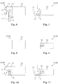
- Fig. 1 shows a schematized top view onto an electronic tag 1.
- Tag 1 comprises a temperature sensor or a sensor for some other physical or environmental condition. The tag can monitor that magnitude and decide whether or not certain (predescribed) conditions concerning that magnitude are met, e.g., whether or not a threshold value has been exceeded and possibly also for how long it has been exceeded. Depending on the monitored (sensed or measured) values (of temperature, pressure, humidity, acceleration or others and usually also of the time), one or more types of alarm indications can be provided by the tag, depending on the type of event or failure that occurred. Since such functionalities are known from prior art, e.g., from RFID tags, we will not go into much detail here concerning this point.
- Tag 1 of Fig. 1 comprises a main part 2 and a rip strip 3 which are mutually interconnected.
- the main part 2 typically has a volume of at most 35 mm x 30 mm x 12 mm, in particular having a side length of, at most, the specified lengths, and more particularly, it may have a volume of at most 25 mm x 20 mm x 10 mm, and in particular a side length of, at most, the specified lengths.
- the main part 2 comprises an electronics unit comprising i.a. a user-operable switch 9 (cf. the dotted hand symbol in Fig. 1 ) and a display 6 substantially consisting of two light emitters 7, 8 such as two LEDs, in particular a red LED and a green LED.
- the rip strip 3 substantially consists of a printed circuit board (PCB) or of a piece or part thereof and more particularly of PCB base material 4 in and/or on which conductor lines 5 are present. It is particularly suitable to provide, as the rip strip 3, an electrically insulating foil 4 such as a polymer foil provided with conductor lines 5.
- the electronics unit (having reference symbol 40 in further figures) and the rip strip 3 may be considered to share one printed circuit board.
- the electronics unit 40 may be considered to be a printed circuit board assembly (PCB assembly or PCBA), i.e. a PCB with components mounted thereon (the components being described above and also below), wherein the PCB forming the rip strip 3 is continuous with the PCB of the PCBA representing the electronics unit 40.
- PCB assembly or PCBA printed circuit board assembly
- Fig. 2 shows a schematic cross-sectional view of an attached electronic tag 1, and at the same time, Fig. 2 may be interpreted to show a schematized detail of a retail package 10.
- the tag 1 of Fig. 2 may be identical with the one of Fig. 1 .
- Tag 1 comprises electronics unit 40 in its main part 2 and rip strip 3, each comprising a portion of one and the same PCB, which may be a flexible PCB.
- Main part 2 comprises a housing 41 in which electronics unit 40 is present.
- Electronics unit 40 comprises, besides the PCB and mounted thereon, an energy source such as a battery 42, the above-mentioned switch 9 which may be, e.g., an electro-mechanical switch or a capacitive switch, the light emitters of the display (only LED 7 being illustrated in Fig. 2 ) and an integrated circuit (IC) 44 such as an ASIC (application-specific IC).
- IC 44 may embody a control unit and a sensor unit, but it is also possible that a separate sensor unit is mounted on the PCB.
- data sensed by a sensor of the sensing unit are continuously (or quasi-continuously) taken, but usually, measuring or sensing takes place in time intervals of between 30 seconds and 12 hours, more particularly between 1 minute and 30 minutes, so as to save energy.
- Housing 41 may be made substantially of a material which is sufficiently transparent for letting light emitted by light emitters 7, 8 of tag 1 pass through such that it is visible from the outside, or may comprise, as indicated in Fig. 2 , a transparent portion 49 for that purpose.
- a double-faced adhesive tape 15 may be used.
- An alternative would be to use a different bonding technique such as the application of an initially liquid bonding material such as a glue. A bonding may take place between the housing 41 and the tag carrier 11, and it is possible, as indicated in Fig. 2 to provide that it takes place, in addition between the battery 42 and the tag carrier 11. In the latter case, the adhesive tape 15 or other bonding material may function as a part of the housing of the tag 1.
- FIG. 3 An alternative way of attaching tag 1 to a tag carrier 11 is illustrated in Fig. 3 .
- the tag may be identical with the one of Fig. 1
- its electronics unit 40 may be identical with the one of Fig. 2 .
- the attaching of main part 2 to tag carrier 11 is accomplished in an indirect way. More specifically: A foil 18 such as a polymer foil holds main part 2 between itself and tag carrier 11. In an area partially surrounding main part 2, foil 18 is bonded to tag carrier 11 using a bonding material such as a glue (indicated at 19 in Fig. 3 , but not separately drawn). Thus, main part 2 is sandwiched between foil 18 and tag carrier 11.
- Suitable tag carriers 11 are, e.g., sheet- or plate-shaped bodies, in particular cardboard or paperboard bodies. Below, a box such as a folding box will be described as a possible tag carrier, and further below, a card to be placed in a box will be described as a possible tag carrier.
- Fig. 4 is a symbolic cross-sectional view of a retail unit 20. It comprises a retail package comprising a tag 1 such as one of the before-described ones and a box 12 as an outer package, and a product 24, wherein the product 24 may be and usually is contained in a container 22, the container usually being located inside box 12, all as illustrated in Fig. 4 .
- Product 24 may be a pharmaceutical product such as one provided in form of pills or capsules, and it is contained, in case of Fig. 4 , in a blister package as a container 22. Usually, there is no further level of packaging between a box 12 and a container 22.
- the product may be contained in a means for applying the product (such as in a syringe containing the product), this means being present in the container 22, e.g., a box 12 may contain a bag containing a syringe containing the product 24.
- a package insert present in box 12, i.e. a leaflet explaining details concerning product 24 (not illustrated in any of the figures).
- Box 12 usually is a folding carton. Pharmaceutical products (and also some other products) are sold (in retail) in folding cartons, at least in most cases.
- One such box may contain one or more containers 22. And one container may contain one or more doses of the product 24.
- a main application of the present invention is related to retail packages and retail units, and thus to outer packages which reach the end user and to single packs, i.e. to the units given to end users such as patients, or - in case of pharmaceutical products given to a patient by a health care specialist - to the health care specialist.
- Fig. 4 illustrates the possibility to attach tag 1 on the outside of box 12.
- At least main part 2 is attached to a tag carrier 11, e.g., to a box 12.
- rip strip 3 is attached to the tag carrier 11, at least in one or more regions of rip strip 3.
- Fig. 5 illustrates the possibility to attach tag 1 on the inside of a box 12, e.g, inside a folding box.
- Fig. 5 is a symbolic cross-sectional view of a retail unit 20 comprising a retail package comprising tag 1 such as one of the before-described ones and box 12 as an outer package, and a product 24, wherein the product 24 may be and usually is contained in a container 22, the container usually being located inside box 12, just as illustrated in Fig. 5 .
- Product 24 may be a pharmaceutical product such as one provided in form of a liquid or a powder, and it is contained, in case of Fig. 5 , in a bottle or flask as a container 22.
- a package insert present in box 12, i.e. a leaflet explaining details concerning product 24 (not illustrated in any of the figures).
- tag 1 Since tag 1 is located inside box 12, tampering with tag 1 is largely inhibited.
- rip strip 3 of a tag 1 is ripped or torn when a box 12 is opened.
- rip strip 3 can be arranged at and attached to a box 12 in such a way that this happens unavoidably (at least unless unusual measures are taken).
- rip strip 3 will be ripped when opening box 12 and accessing product 24, respectively.
- a tag 1, e.g., one as described above, and, more particularly, the corresponding electronics unit 40 can be structured and configured for detecting an interruption of a conductor line loop of rip strip 3 such as the one occurring in the way described above for Fig. 5 or in another way (e.g., by cutting rip strip 3 using a cutting tool or by ripping rip strip 3 by hand). And, morever, this may result in a termination of the monitoring (and of the measurements and of the sensing) being accomplished (or at least evaluated) by the tag 1.
- monitoring the integrity of a product 24 is carried out from a starting event (e.g., when product 24 - and usually also a container 22 - is packaged in the retail package and thus in a box 12) to an end point, wherein the end point is indicated by a ripping of rip strip 3, and wherein this ripping can be linked to an accessing of product 24, namely by providing that rip strip 3 is ripped when box 12 is opened.
- a starting event e.g., when product 24 - and usually also a container 22 - is packaged in the retail package and thus in a box 12
- a ripping of rip strip 3 e.g., when product 24 - and usually also a container 22 - is packaged in the retail package and thus in a box 12
- this ripping can be linked to an accessing of product 24, namely by providing that rip strip 3 is ripped when box 12 is opened.
- the integrity status of product 24 may, also in reaction to said ripping, be stored in tag 1 such that it can be recalled later (namely by operating switch 9, cf. Figs. 1-3 ) and/or may be displayed by the display 6 of tag 1, e.g., by the emission of light pulses.
- a "forced" ripping upon accessing the product 24 as described in conjunction with Fig. 4 , one can, e.g., provide that an opening of any openable sides results in a ripping of rip strip 3, e.g., by suitably bonding (e.g., gluing) rip strip 3 (of sufficient length) to each of the openable sides. Or it can be provided that only one side of box can be opened. The latter can be accomplished in case of a (standard) folding carton by sealing the other one of the two openable sides, e.g., by bonding (e.g., gluing) a flap to another side of the folding carton or by applying a self-adhesive piece of tape.
- a (standard) folding carton by sealing the other one of the two openable sides, e.g., by bonding (e.g., gluing) a flap to another side of the folding carton or by applying a self-adhesive piece of tape.
- rip strip 3 is bent in the way indicated by the dashed arrow and bond it there to box 12.
- an attaching (bonding; gluing) of rip strip 3 to the tag carrier 11 can constitute a security measure for preventing tampering with the tag 1.
- a beginning of the time span during which the physical or environmental conditions are monitored may be indicted by breaking another loop present on rip strip 3, cf. also Fig. 17 below.
- E.g., dividing the rip strip of Fig. 1 along the dashed line s1 (and thus opening the longer one of the two loops present on rip strip 3) may be detected by electronics unit 40 (and more particularly by a control unit realized therein) by an increase of an ohmic resistance and make the electronics unit 40 start the monitoring.
- dividing the rip strip of Fig. 1 along the dashed line s2 may be detected by electronics unit 40 (and more particularly by a control unit realized therein) by an increase of an ohmic resistance and make the electronics unit 40 terminate (stop) the monitoring.
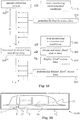
- Fig. 19 is another illustration of the possibility to provide a tag 1 on the inside of a box 12, e.g, inside a folding box.
- the embodiment of Fig. 19 is very similar to the one of Fig. 5 . Therefore, refer to the description of Fig. 5 for further details. But the embodiment of Fig. 19 differs therefrom in that a portion of the tag 1 is attached to container 22.
- the case has been selected that main part 2 of tag 1 is attached to container 22.
- rip strip 3 is attached to container 22 (as an alternative or in addition) or to have a non-attached rip strip 3 (merely connected to main part 2).
- rip strip 3 is attached to the box 12, more particularly to an inner side of box 12. It is possible to provide that both, main part 2 and rip strip 3, are attached to container 22.
- Fig. 20 is another symbolic cross-sectional view of a retail unit 20.
- tag 1 is attached to a container 22 present inside box 12.
- container 22 is a bag which usually is at least partially constituted by a polymer foil, in particular by transparent polymer foil.
- Product 24 itself is present in a syringe which is present inside container 22.
- Fig. 20 illustrates the possibility to have one portion of tag 1, e.g., as illustrated, main part 2, attached to container 22, whereas another portion, e.g., as illustrated, rip strip 3, is free (not directly attached to a package component).
- Figs. 6 to 11 are symbolic views of a retail package 10 or (in case a product is inside) a retail unit 20, at various stages.
- Figs. 6, 8, 10 are top views
- Figs. 7, 9, 11 are side views.
- the setup is similar to the one of Fig. 5 , but main part 2 of tag 1 is attached to an openable side part of the box 12, and rip strip 3 is partially inside and partially outside box 12 (when box 12 is closed and before it is opened).
- a tag 1 e.g., a tag of the before-described kind, is attached on the inner side of an openable side part 13 of box 12.
- Main part 2 and a first portion of rip strip 3 (close to main part 2) are bonded to openable side part 13.
- a distal portion of rip strip 3 is free (not attached to box 13), projecting from box 12 and, more particularly from side part 13.
- box 12 is closed and a flap or tongue 14 of box 12 is inserted.
- a portion of the rip strip 3 is bonded to another side part of box 12, namely the formerly projecting portion or a portion thereof.
- the first loop can be interrupted, namely by ripping (cutting, tearing) rip strip 3 in a first region (where ripping interrupts the first but not the second loop, cf. dashed line s2 in Fig. 1 ), so as to start the monitoring of the integrity of the product.
- ripping cutting, tearing
- rip strip 3 is interrupted, namely by ripping (cutting, tearing) rip strip 3 in a first region (where ripping interrupts the first but not the second loop, cf. dashed line s2 in Fig. 1 ), so as to start the monitoring of the integrity of the product.
- the monitoring can be started differently, cf. below at the description of Fig. 18 ("initiating switch").
- a single conductor line loop may be sufficient, and rip strip 3 may remain unripped at least until after packaging, i.e. at least up to forwarding / shipping it.
- the whole projecting portion of rip strip 3 (cf. Fig. 6 ) is still present and continuous when it (or a portion of it) is bonded to box 12.
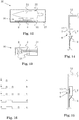
- Figs. 10, 11 show the situation when box is opened (in the intended way).
- this is the situation usually present when an end-user such as a patient or a health care specialist is about to use or apply (or firstly use or apply) the product 24 retailed in retail package 10.
- an end-user such as a patient or a health care specialist is about to use or apply (or firstly use or apply) the product 24 retailed in retail package 10.
- flap 14 and turning side part 13 another ripping of the rip strip takes place, such that the monitoring is ended and a final integrity status is obtained by tag 1 and/or stored in tag 1 and/or displayed by tag 1.
- the other conductor line loop is interrupted (cf. dashed line s1 in Fig. 1 ), such that merely a portion 3a of rip stip 3 remains with main part 2 on side part 13 of box 12, and another portion, referenced 3c in Fig. 11 , remains at the other side part of box.
- Figs. 12 and 13 illustrate another way of using a tag 1 such as the above-described tag 1.
- Fig. 12 is a symbolic cross-sectional view of a retail unit 20 containing a card unit 30 (as a tag carrier) comprising and, in particular, substantially consisting of a card 31 with attached electronic tag 1
- Fig. 13 is a symbolic top view onto the card unit 30 of Fig. 12 .
- tag 1 is not attached to box 12, and thus, the above-described effect of unavoidably breaking an electrical contact (and thus providing a signal for stopping the monitoring) when opening box 12 is not achieved.
- Tag 1 is bonded to card 31, wherein usually both, main part 2 and rip strip 3 are bonded to card 31.
- card 31 On card 31, one or more text areas 32 may be provided in which text and/or figures are printed. Corresponding text and/or figures may be explicative for the use of card unit 30 and, more particularly for the use of tag 1.
- text areas 32 it may be explained that card 31 (and more particularly rip strip 3) shall be cut or ripped in a prescribed region, such in the location indicated on card 31, cf. the dotted line in Fig. 13 .
- box 12 When shipping retail unit 20, not only container 22 (in Fig. 12 a tube) is present inside box 12, but also card unit 30 (and usually also a package insert explaining details concerning product 24).
- Box 12 can be a folding carton, and card 31 (functioning as the tag carrier) can be a piece of cardboard or paperboard.
- Fig. 14 shows a detail of a symbolic cross-sectional view of a retail package 20 with an electronic tag 1 visible through a transparent portion or window 17 of box 12.
- Tag 1 may be a tag 1 as described above.
- Main part 2 of tag 1 is located inside box 12, and window 17 and tag 1 are arranged such that the display (cf., e.g., display 6 in Fig. 1 ) of tag 1 is visible through window 17.
- Rip strip 3 may be fully inside box 12, or may be partially outside box 12, e.g., bonded to box 12 (like, e.g., in Figs. 9, 11 ) or free (like in Fig. 4 ).
- operating switch 9 results in display 6 displaying data related to the product integrity, more specifically in an emission of visible signals indicating the (current) product integrity status.
- switch 9 is a contactless switch such as a capacitive switch.
- Fig. 15 is very similar to the one of Fig. 14 and illustrates a detail of a symbolic cross-sectional view of another retail package 20 with an electronic tag 1 visible through a window 17.
- tag 1 and window 17 and the way of fixing tag 1 to box 12 is different.
- an arrangement according to Fig. 15 may be mechanically more stable.
- Main part 2 is directly (and, e.g., at its circumference) attached to a side part of box 12. It may or may not be attached to window 17, too.
- a display 6 of a tag 1 of one of the above-described kinds may comprise one or more light emitters such as LEDs, in particular light emitters of different color, e.g., one emitting red light and another emitting green light.
- a control unit of tag 1 e.g., an integrated circuit, e.g., the one of Figs. 2, 3 , may control the display 6 to emit light pulses, more particularly sequences of light pulses (wherein already a single light pulse shall be considered a sequence of light pulses). Emitted light pulses in a sequence may differ in at least one of color, duration, intensity.
- the emission of green light may be emitted in order to indicate that the product integrity is still in order
- the emission of red light may be emitted in order to indicate that the product integrity is not in order anymore.
- the duration (of a pulse in a sequence) is a parameters which can be varied for displaying integrity status information, it can be provided, e.g., that two or more types of alarm (or types of failures) are indicated by different pulse durations.
- An example will be illustrated and described by means of Fig. 16 .
- Fig. 16 is an illustration of sequences of light pulses emittable by an electronic tag 1 such as by an above-described tag 1.
- the curves "a” to "e” illustrate different sequence which may be emitted in 5 different cases, i.e. in five different integrity statuses.
- the horizontal axis is the time axis
- the vertical axis is the light intensity axis, intensities being either zero or a maximum value.
- the (partial) sequence for the additional failure(s) is appended to the long red light pulse indicating the third type failure.
- Curve e indicates the case that a failure of a first type and a failure of a third type have occurred.
- a failure of first type may mean, e.g., that an upper temperature limit T(up) has been exceeded.
- a failure of second type may mean, e.g., that a lower temperature limit T(low) has been fallen short of.
- a failure of third type may mean, e.g., that a threshold temperature limit T(thr) has been exceeded (or fallen short of) for a too long time, more particularly for more than a predescribed threshold time t(thr).
- Such a kind of data indicative of predescribed limitations of a product e.g., T(up), T(low), T(thr) and t(thr) are usually stored in the electronics unit. They may be programmable in a way described further above in the present patent application. If programming pads are provided for programming such values, these may in particular be provided on the rip strip.
- Fig. 21 illustrates a possible design of a rip strip with contact pads for programming such values.
- Fig. 21 shows an illustration of a top view onto an electronic tag 1.
- This tag 1 can be largely identical with other tags described in the present patent application, such as tag 1 of Fig. 1 , but the rip strip 3 is designed to provide two contact pads 60, 66. While conductor lines 5 form two loops LI, L2 which may (as illustrated) partially overlap and are readily interrupted by ripping rip strip 3 along separation lines s1, s2, conductor line 50 provides an electrical connection between pad 60 and the electronics unit of tag 1, and conductor line 55 provides an electrical connection between pad 66 and the electronics unit of tag 1.
- data indicative of predescribed limitations of a product to be monitored may be programmed before ripping rip strip 3 along s1 or s2.
- a (high) number of such tags 1 may be present, and an arbitrary one of them is selected for the next product, and then - when the type of product to be packaged is known - said data indicative of predescribed limitations of that specific product for the exposure of that specific product to the monitored physical or environmental conditions are programmed (using pads 60 and 66).
- the provision of a single type of tag 1 can be sufficient for packaging (and monitoring) in that packaging line a plurality of different products (with different predescribed limitations). Accordingly, storing various different types of tags, each specifically designed for the different products to be packaged (set to the respective specific predescribed limitaions for the exposure of said product to said physical or environmental conditions), may become superfluous this way.
- green light pulses If product integrity is in order, this may be indicated by one or more green light pulses. It is, more specifically, possible to distiguish different types of (still-)in-order statuses. E.g., in a first case, a single green pulse is emitted, cf., e.g., curve a or curve e. And in a second case, two green pulses are emitted, cf., e.g., curve b, or more than two pulses are emitted, or green an red pulses are emitted.
- a single green pulse is emitted, cf., e.g., curve a or curve e.
- two green pulses are emitted, cf., e.g., curve b, or more than two pulses are emitted, or green an red pulses are emitted.
- the first (still-)in-order status case may be, e.g., that no threshold value has been reached. In case a temperature is monitored, this would be the case, e.g., if the temperature never left the range at which the product may be kept forever or (as more often will be the case) until its expiration date.
- the second (still-)in-order status case may be, e.g., that for more than a pre-selected time duration, a threshold value has been exceeded and fallen short of, respectively, (depending on the threshold being an upper and a lower threshold value, respectively).
- a threshold value e.g., if the temperature of the product may be above an upper threshold of, e.g., 37°C for at most, e.g., 72 hours, and an alarm is desired as soon as only 24 hours or less are left (24 hours being the pre-selected time duration). If then the temperature has in fact been above 37°C for already more than than 48 hours, such that the product will be in order for only less than 24 hours (provided that its temperature will remain above 37°C), the second (still-)in-order status shall be indicated.
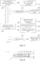
- Fig. 17 illustrates method steps.
- Reference symbol t denotes the time
- dt denotes the time span during which monitoring takes place.
- steps 100, 110 the time span during which integrity monitoring shall take place is started by interrupting a first electrical contact, e.g., by opening a conductor line loop, cf. also dashed line s2 in Fig. 1 .
- Operating switch 9 during the subsequent time span results in a displaying of the status data (step 130).
- step 140 interrupting another electrical contact results in terminating the time span and the monitoring (step 150), obtaining the final status data (step 160) and displaying the final status data (step 170).
- step 180 When later on, switch 9 is operated (step 180), the final status data are displayed (step 190).
- the status data will not be permanently displayed, but only when the switch 9 is operated; and optionally also when the time span (and thus the monitoring) is terminated and/or optionally in (regular) time intervals (controlled by the control unit), the time intervals being usually between 1 second and 2 minutes, more particularly between 10 seconds and 1 minute.
- Fig. 18 is another illustration of method steps, similar to the one of Fig. 17 . It illustrates an unclaimed example for the case that no switch is required for displaying the status data. Instead, the status data are displayed periodically, before and after terminating the monitoring, cf. steps 230 and 290. And Fig. 18 also illustrates an unclaimed example for the case that monitoring is started without needing a rip strip for that purpose. Instead, the monitoring is started in reaction to the operation of a switch, referred to as initiating switch, cf. step 200. It can be referred to Fig. 2 for illustrating a corresponding electronic tag 1, wherein the item referenced 9 in this case is interpreted as such an initiating switch, i.e.
- a switch when operated, effecting that the monitoring starts.
- a switch may be an electro-mechanical switch, a capacitive switch, a magnetic switch or an inductive switch. Note that it is possible to nevertheless provide in this case a rip strip - in particular for the unclaimed purpose of terminating the monitoring. But alternatives thereto are possible, e.g., a switch (e.g., the before-mentioned initiating switch) may be provided for that purpose.
- the initiating switch may in particular be a magnetic or inductive switch.
- the manufacturing of the retail package or retail unit may comprise moving the same along a path along which a suitable magnet (permanent or electromagnet) and a suitable coil, respectively, is suitably positioned., e.g., along a path described by a conveyor transporting the retail package or retail unit. Then, while passing along the respective magnetic or electric field, the initiating switch is operated (without mechanically contacting the tag), and the monitoring starts.
- the initiating switch might also be an electro-mechanical or a capacitive switch, the latter also allowing a contact-free operation.
- a displaying of the status data can be initiated (display switch).
- This switch (sufficiently described above) may be identical with the unclaimed initiating switch or be an additional switch.
- the switches may be identical, it may be provided that different effects may be provoked by differently operating the switch. E.g., a brief operation of the switch (e.g., for at most 1.5 seconds) provokes a displaying of the status data, whereas a longer operation (e.g., for st least 3 seconds) can effect that the monitoring starts.
- the unclaimed function of the rip strip (for terminating the monitoring) may also be assumed, as claimed, by the switch, e.g., termination of monitoring is in that case effected in reaction to operating the switch for an even longer time (e.g., for at least 8 seconds).
- the rip strip may be dispensed with.
- the tag, the retail package and the retail unit described in the present patent application are easy to use and operable by untrained personnel, i.e. by people not specifically instructed on how to use the tag, the retail package, the retail unit, as far as the integrity monitoring is concerned.
- patients and health care specialists who apply or use the pharmaceutical product can, without additional measures and without the need of additional tools, check the integrity of the product to be applied or used. And this can be accomplished (at least approximately) at the time when the product is applied or used.
- the manufacturer or distributor can check the integrity status of the product by using the tag. Based thereon, it can, e.g., be decided whether or not to forward the product to another acquirer or user.
- the manufacturer or distributor forwards the product to another acquirer or user. That other acquirer or user can then (usually when the box is opened and the product is to be applied) check the integrity status of the product using the herein described tag.
- the tag, the retail package and the retail unit provide standalone solutions which do not require further equipment.
- the attaching of the tag to a box can be accomplished by the manufacturer or by the packaging company packaging the product in the box (typically packing the container or containers containing the product in the box).
- the tag in a non-claimed embodiment, may consist of merely
- the PCB can be sufficient for electrically contacting the energy source (battery), cf. Figs. 2, 3 , such that no separate battery holder needs to be provided.
- the rip strip may be dispensed with (at least in its function as providing a means for starting the monitoring) and/or the switch may be dispensed with (at least in its function as a means for requesting a displaying of the status data, and this at least for times not coinciding with the time of terminating the monitoring).
- a display of an above-described kind can be particularly small and cost-efficient. There is no need for a liquid crystal display or the like.
Landscapes
- Engineering & Computer Science (AREA)
- Microelectronics & Electronic Packaging (AREA)
- Computer Hardware Design (AREA)
- Theoretical Computer Science (AREA)
- General Physics & Mathematics (AREA)
- Physics & Mathematics (AREA)
- Health & Medical Sciences (AREA)
- Animal Behavior & Ethology (AREA)
- Veterinary Medicine (AREA)
- Public Health (AREA)
- General Health & Medical Sciences (AREA)
- Life Sciences & Earth Sciences (AREA)
- Pharmacology & Pharmacy (AREA)
- Packages (AREA)
- Details Of Rigid Or Semi-Rigid Containers (AREA)
Claims (10)
- Etiquette électronique (1) permettant d'obtenir à propos de l'intégrité d'un produit (24) des informations déterminées à partir de l'exposition dudit produit (24) à des conditions physiques ou environnementales pendant une certaine durée, ladite étiquette électronique comprenant :- une partie principale (2) contenant une unité électronique (40),ladite unité électronique (40) comprenant :- une unité de commande,- une unité de détection comprenant au moins un détecteur qui surveille lesdites conditions physiques ou environnementales,- une unité d'affichage comprenant un affichage (6) qui affiche des informations à propos de l'intégrité, appelées données d'état,- un commutateur (9) appelé commutateur d'affichage (9),ladite unité de commande étant structurée et configurée pour faire afficher par ladite unité d'affichage les données d'état en réaction à l'actionnement dudit commutateur d'affichage (9), caractérisée en ce que
ladite unité électronique comprend un commutateur appelé commutateur à terminer, le commutateur d'affichage et le commutateur à terminer étant identiques ou différant l'un de l'autre,
en ce que l'étiquette (1) comprend un ruban déchirable (3) contenant une connexion électrique connectée fonctionnellement à ladite unité électronique (40),
en ce que ladite unité de commande est structurée et configurée pour :- détecter une rupture de ladite connexion électrique,- lancer ladite surveillance en réaction à ladite détection de ladite rupture de ladite connexion électrique et- terminer ladite surveillance en réaction audit actionnement dudit commutateur à terminer. - Etiquette électronique (1) selon la revendication 1, dans laquelle ledit ruban déchirable (3) comprend ou est essentiellement constitué d'une carte de circuit imprimé, en particulier une carte flexible de circuit imprimé.
- Etiquette électronique (1) selon la revendication 2, dans laquelle la carte de circuit imprimé est une carte rigide de circuit imprimé connectée fonctionnellement à l'unité électronique (40).
- Etiquette électronique (1) selon l'une des revendications 1 à 3, l'étiquette (1) ne comprenant pas de capacité de réponse à radio-identification.
- Emballage (10) de vente au détail d'un produit périssable (24), ledit emballage de vente au détail comprenant :- une boîte (12) formant un emballage extérieur et- une étiquette (1) selon l'une des revendications 1 à 4.
- Emballage (10) selon la revendication 5, dans lequel ledit ruban déchirable (3) est relié à l'extérieur de la boîte (12).
- Emballage (10) selon l'une des revendications 5 et 6, dans lequel ladite boîte (12) est une boîte en carton et plus particulièrement un carton replié.
- Unité (20) de vente au détail comprenant un emballage (10) de vente au détail selon l'une des revendications 5 à 7 et comprenant en outre ledit produit périssable (24).
- Unité (20) de vente au détail selon la revendication 8, dans laquelle ledit produit périssable (24) est un produit pharmaceutique (24).
- Procédé de fabrication d'une unité (20) de vente au détail comprenant un produit périssable (24), ledit procédé comprenant les étapes :a) prévoir ledit produit (24),b) prévoir un carton repliable déplié,c) replier ledit carton repliable,d) insérer ledit produit (24) dans le carton repliable replié,e) prévoir une étiquette électronique (1) selon l'une des revendications 1 à 4,f) relier ladite étiquette (1) audit carton repliable etg) lancer la surveillance de ladite exposition dudit produit (24) auxdites conditions physiques ou environnementales en déchirant le ruban déchirable (3) de l'étiquette (1),l'étape g) étant réalisée avant que l'étape f) le soit.
Applications Claiming Priority (4)
| Application Number | Priority Date | Filing Date | Title |
|---|---|---|---|
| CH9722013 | 2013-05-15 | ||
| CH12082013 | 2013-07-04 | ||
| PCT/CH2014/000067 WO2014183226A1 (fr) | 2013-05-15 | 2014-05-13 | Emballage de produit pharmaceutique comprenant une étiquette électronique miniaturisée de surveillance d'intégrité de produit |
| EP14727150.6A EP2997523B1 (fr) | 2013-05-15 | 2014-05-13 | Emballage de produit pharmaceutique comprenant une étiquette électronique miniaturisée de surveillance d'intégrité de produit |
Related Parent Applications (1)
| Application Number | Title | Priority Date | Filing Date |
|---|---|---|---|
| EP14727150.6A Division EP2997523B1 (fr) | 2013-05-15 | 2014-05-13 | Emballage de produit pharmaceutique comprenant une étiquette électronique miniaturisée de surveillance d'intégrité de produit |
Publications (2)
| Publication Number | Publication Date |
|---|---|
| EP3327632A1 EP3327632A1 (fr) | 2018-05-30 |
| EP3327632B1 true EP3327632B1 (fr) | 2021-01-20 |
Family
ID=50841988
Family Applications (2)
| Application Number | Title | Priority Date | Filing Date |
|---|---|---|---|
| EP17206676.3A Active EP3327632B1 (fr) | 2013-05-15 | 2014-05-13 | Emballage pour produit pharmaceutique comprenant une étiquette électronique miniaturisée permettant de surveiller l'intégrité du produit |
| EP14727150.6A Active EP2997523B1 (fr) | 2013-05-15 | 2014-05-13 | Emballage de produit pharmaceutique comprenant une étiquette électronique miniaturisée de surveillance d'intégrité de produit |
Family Applications After (1)
| Application Number | Title | Priority Date | Filing Date |
|---|---|---|---|
| EP14727150.6A Active EP2997523B1 (fr) | 2013-05-15 | 2014-05-13 | Emballage de produit pharmaceutique comprenant une étiquette électronique miniaturisée de surveillance d'intégrité de produit |
Country Status (5)
| Country | Link |
|---|---|
| US (1) | US10441506B2 (fr) |
| EP (2) | EP3327632B1 (fr) |
| DK (1) | DK3327632T3 (fr) |
| ES (1) | ES2859626T3 (fr) |
| WO (1) | WO2014183226A1 (fr) |
Families Citing this family (6)
| Publication number | Priority date | Publication date | Assignee | Title |
|---|---|---|---|---|
| US8092251B2 (en) * | 2007-12-29 | 2012-01-10 | Apple Inc. | Active electronic media device packaging |
| PL411015A1 (pl) * | 2015-01-21 | 2016-08-01 | Zbigniew Bigaj | Węzeł logistyczny z identyfikowalnością stanu zawartości opakowania oraz opakowanie transportowe z monitorowaniem temperatury do produktów wrażliwych na temperaturę |
| CH711618A2 (en) * | 2015-10-07 | 2017-04-13 | Tecpharma Licensing Ag | Administration device with activatable identification means. |
| US20190138864A1 (en) * | 2016-04-18 | 2019-05-09 | Thin Film Electronics Asa | Smart label or tag having a continuity sensor on a substrate having a preferential tearing direction and system including the same |
| US10739211B2 (en) * | 2016-12-16 | 2020-08-11 | Vdw Design, Llc | Chipless RFID-based temperature threshold sensor |
| US11810041B2 (en) * | 2020-10-13 | 2023-11-07 | Inteligistics, Inc. | System, method, and computer program product for predicting perishable product temperatures and quality |
Family Cites Families (11)
| Publication number | Priority date | Publication date | Assignee | Title |
|---|---|---|---|---|
| US7978564B2 (en) * | 1997-03-28 | 2011-07-12 | Carlos De La Huerga | Interactive medication container |
| US20040066296A1 (en) * | 2001-11-15 | 2004-04-08 | Atherton Peter S. | Tamper indicating radio frequency identification label with tracking capability |
| GB0304841D0 (en) * | 2003-03-04 | 2003-04-09 | Koninkl Philips Electronics Nv | Wireless transmission tag, product fitted with such a tag, communication system including such a tag and communication method for such a system |
| US7764183B2 (en) * | 2005-04-22 | 2010-07-27 | Infratab, Inc. | Apparatus and method for monitoring and communicating data associated with a product |
| US7948381B2 (en) * | 2004-04-30 | 2011-05-24 | Binforma Group Limited Liability Company | Reversibly deactivating a radio frequency identification data tag |
| CN101002216A (zh) * | 2004-08-11 | 2007-07-18 | 皇家飞利浦电子股份有限公司 | 监控容易腐烂产品的到期日期 |
| DE102006010159A1 (de) | 2006-02-27 | 2007-09-06 | GTI Gesellschaft für technische Informatik GmbH | Elektronisches Etikett sowie Verfahren zur Überwachung von Gut |
| US8830072B2 (en) | 2006-06-12 | 2014-09-09 | Intelleflex Corporation | RF systems and methods for providing visual, tactile, and electronic indicators of an alarm condition |
| US20090189763A1 (en) * | 2008-01-28 | 2009-07-30 | Kenneth Brinkley | Security film |
| GB2469100A (en) | 2009-04-02 | 2010-10-06 | Roger Lucien Bailhache | Expiry indicator |
| US9294283B2 (en) | 2011-08-31 | 2016-03-22 | Q-Tag Ag | Methods and devices for monitoring the integrity of an article during transporting said article |
-
2014
- 2014-05-13 EP EP17206676.3A patent/EP3327632B1/fr active Active
- 2014-05-13 WO PCT/CH2014/000067 patent/WO2014183226A1/fr not_active Ceased
- 2014-05-13 EP EP14727150.6A patent/EP2997523B1/fr active Active
- 2014-05-13 US US14/890,508 patent/US10441506B2/en active Active
- 2014-05-13 ES ES17206676T patent/ES2859626T3/es active Active
- 2014-05-13 DK DK17206676.3T patent/DK3327632T3/da active
Non-Patent Citations (1)
| Title |
|---|
| None * |
Also Published As
| Publication number | Publication date |
|---|---|
| US10441506B2 (en) | 2019-10-15 |
| WO2014183226A1 (fr) | 2014-11-20 |
| EP2997523B1 (fr) | 2018-01-03 |
| US20160166470A1 (en) | 2016-06-16 |
| EP2997523A1 (fr) | 2016-03-23 |
| ES2859626T3 (es) | 2021-10-04 |
| DK3327632T3 (da) | 2021-04-12 |
| EP3327632A1 (fr) | 2018-05-30 |
Similar Documents
| Publication | Publication Date | Title |
|---|---|---|
| US10646640B2 (en) | Monitoring product integrity of a pharmaceutical product in a syringe using a miniaturized electronic sensor tag | |
| EP3327632B1 (fr) | Emballage pour produit pharmaceutique comprenant une étiquette électronique miniaturisée permettant de surveiller l'intégrité du produit | |
| EP3022688B1 (fr) | Surveillance d'intégrité de produit d'un produit pharmaceutique dans un flacon à l'aide d'une étiquette de capteur électronique miniaturisée | |
| US7726485B2 (en) | Momentary switch integrated in packaging of an article | |
| US7760084B2 (en) | Redundant monitoring | |
| JP2009528629A (ja) | 環境検出 | |
| US20160103085A1 (en) | Connected packaging | |
| DK3104823T3 (en) | DEVICE FOR DISPOSAL OF REMOVAL OF MEDICINAL PRODUCTS | |
| US11382836B2 (en) | Medicament dispensing system and dispensing method | |
| WO2011072296A2 (fr) | Indicateur de sécurité alimentaire | |
| US10589910B2 (en) | Container with expiration date alarm | |
| WO2014123463A1 (fr) | Emballage destiné à contenir un produit | |
| EP3312774B1 (fr) | Emballage pour produit pharmaceutique, comprenant une étiquette électronique miniaturisée permettant de surveiller l'intégrité du produit | |
| JP5372005B2 (ja) | 医療用複室容器及びこれを用いた薬剤混合の認識方法、医療用複室容器の誤使用防止システム、薬剤入り医療用複室容器 | |
| DK2997523T3 (en) | Packaging for pharmaceutical products, including a miniaturized electronic label for product integrity monitoring | |
| US20170369207A1 (en) | Device for checking whether a package has been opened or not and method for producing said device | |
| TWI657244B (zh) | 具有電子裝置之用於儲存如煙草材料或煙草替代材料之材料的產品 | |
| JP2006084696A (ja) | 封印テープおよびそれを有する物品 | |
| CA2871873A1 (fr) | Mecanismes de surveillance de la conformite, de facilitation de la distribution automatique et de positionnement de bande a l'epreuve des enfants sur un medicament emballe |
Legal Events
| Date | Code | Title | Description |
|---|---|---|---|
| PUAI | Public reference made under article 153(3) epc to a published international application that has entered the european phase |
Free format text: ORIGINAL CODE: 0009012 |
|
| STAA | Information on the status of an ep patent application or granted ep patent |
Free format text: STATUS: THE APPLICATION HAS BEEN PUBLISHED |
|
| AC | Divisional application: reference to earlier application |
Ref document number: 2997523 Country of ref document: EP Kind code of ref document: P |
|
| AK | Designated contracting states |
Kind code of ref document: A1 Designated state(s): AL AT BE BG CH CY CZ DE DK EE ES FI FR GB GR HR HU IE IS IT LI LT LU LV MC MK MT NL NO PL PT RO RS SE SI SK SM TR |
|
| STAA | Information on the status of an ep patent application or granted ep patent |
Free format text: STATUS: REQUEST FOR EXAMINATION WAS MADE |
|
| 17P | Request for examination filed |
Effective date: 20181122 |
|
| RBV | Designated contracting states (corrected) |
Designated state(s): AL AT BE BG CH CY CZ DE DK EE ES FI FR GB GR HR HU IE IS IT LI LT LU LV MC MK MT NL NO PL PT RO RS SE SI SK SM TR |
|
| STAA | Information on the status of an ep patent application or granted ep patent |
Free format text: STATUS: EXAMINATION IS IN PROGRESS |
|
| 17Q | First examination report despatched |
Effective date: 20190205 |
|
| GRAP | Despatch of communication of intention to grant a patent |
Free format text: ORIGINAL CODE: EPIDOSNIGR1 |
|
| STAA | Information on the status of an ep patent application or granted ep patent |
Free format text: STATUS: GRANT OF PATENT IS INTENDED |
|
| RIC1 | Information provided on ipc code assigned before grant |
Ipc: G09F 3/03 20060101ALI20200127BHEP Ipc: A61J 1/18 20060101ALI20200127BHEP Ipc: G06K 19/07 20060101AFI20200127BHEP Ipc: G06K 19/077 20060101ALI20200127BHEP Ipc: A61J 1/03 20060101ALI20200127BHEP |
|
| INTG | Intention to grant announced |
Effective date: 20200224 |
|
| RAP1 | Party data changed (applicant data changed or rights of an application transferred) |
Owner name: BERLINGER & CO. AG |
|
| GRAJ | Information related to disapproval of communication of intention to grant by the applicant or resumption of examination proceedings by the epo deleted |
Free format text: ORIGINAL CODE: EPIDOSDIGR1 |
|
| STAA | Information on the status of an ep patent application or granted ep patent |
Free format text: STATUS: EXAMINATION IS IN PROGRESS |
|
| GRAP | Despatch of communication of intention to grant a patent |
Free format text: ORIGINAL CODE: EPIDOSNIGR1 |
|
| STAA | Information on the status of an ep patent application or granted ep patent |
Free format text: STATUS: GRANT OF PATENT IS INTENDED |
|
| INTC | Intention to grant announced (deleted) | ||
| INTG | Intention to grant announced |
Effective date: 20200805 |
|
| GRAS | Grant fee paid |
Free format text: ORIGINAL CODE: EPIDOSNIGR3 |
|
| GRAA | (expected) grant |
Free format text: ORIGINAL CODE: 0009210 |
|
| STAA | Information on the status of an ep patent application or granted ep patent |
Free format text: STATUS: THE PATENT HAS BEEN GRANTED |
|
| AC | Divisional application: reference to earlier application |
Ref document number: 2997523 Country of ref document: EP Kind code of ref document: P |
|
| AK | Designated contracting states |
Kind code of ref document: B1 Designated state(s): AL AT BE BG CH CY CZ DE DK EE ES FI FR GB GR HR HU IE IS IT LI LT LU LV MC MK MT NL NO PL PT RO RS SE SI SK SM TR |
|
| REG | Reference to a national code |
Ref country code: GB Ref legal event code: FG4D |
|
| REG | Reference to a national code |
Ref country code: CH Ref legal event code: EP |
|
| REG | Reference to a national code |
Ref country code: DE Ref legal event code: R096 Ref document number: 602014074498 Country of ref document: DE |
|
| REG | Reference to a national code |
Ref country code: AT Ref legal event code: REF Ref document number: 1357040 Country of ref document: AT Kind code of ref document: T Effective date: 20210215 |
|
| REG | Reference to a national code |
Ref country code: IE Ref legal event code: FG4D |
|
| REG | Reference to a national code |
Ref country code: CH Ref legal event code: NV Representative=s name: FREI PATENTANWALTSBUERO AG, CH |
|
| REG | Reference to a national code |
Ref country code: SE Ref legal event code: TRGR |
|
| REG | Reference to a national code |
Ref country code: NL Ref legal event code: FP |
|
| REG | Reference to a national code |
Ref country code: DK Ref legal event code: T3 Effective date: 20210408 |
|
| REG | Reference to a national code |
Ref country code: LT Ref legal event code: MG9D |
|
| REG | Reference to a national code |
Ref country code: AT Ref legal event code: MK05 Ref document number: 1357040 Country of ref document: AT Kind code of ref document: T Effective date: 20210120 |
|
| PG25 | Lapsed in a contracting state [announced via postgrant information from national office to epo] |
Ref country code: GR Free format text: LAPSE BECAUSE OF FAILURE TO SUBMIT A TRANSLATION OF THE DESCRIPTION OR TO PAY THE FEE WITHIN THE PRESCRIBED TIME-LIMIT Effective date: 20210421 Ref country code: FI Free format text: LAPSE BECAUSE OF FAILURE TO SUBMIT A TRANSLATION OF THE DESCRIPTION OR TO PAY THE FEE WITHIN THE PRESCRIBED TIME-LIMIT Effective date: 20210120 Ref country code: HR Free format text: LAPSE BECAUSE OF FAILURE TO SUBMIT A TRANSLATION OF THE DESCRIPTION OR TO PAY THE FEE WITHIN THE PRESCRIBED TIME-LIMIT Effective date: 20210120 Ref country code: NO Free format text: LAPSE BECAUSE OF FAILURE TO SUBMIT A TRANSLATION OF THE DESCRIPTION OR TO PAY THE FEE WITHIN THE PRESCRIBED TIME-LIMIT Effective date: 20210420 Ref country code: PT Free format text: LAPSE BECAUSE OF FAILURE TO SUBMIT A TRANSLATION OF THE DESCRIPTION OR TO PAY THE FEE WITHIN THE PRESCRIBED TIME-LIMIT Effective date: 20210520 Ref country code: BG Free format text: LAPSE BECAUSE OF FAILURE TO SUBMIT A TRANSLATION OF THE DESCRIPTION OR TO PAY THE FEE WITHIN THE PRESCRIBED TIME-LIMIT Effective date: 20210420 Ref country code: LT Free format text: LAPSE BECAUSE OF FAILURE TO SUBMIT A TRANSLATION OF THE DESCRIPTION OR TO PAY THE FEE WITHIN THE PRESCRIBED TIME-LIMIT Effective date: 20210120 |
|
| PG25 | Lapsed in a contracting state [announced via postgrant information from national office to epo] |
Ref country code: AT Free format text: LAPSE BECAUSE OF FAILURE TO SUBMIT A TRANSLATION OF THE DESCRIPTION OR TO PAY THE FEE WITHIN THE PRESCRIBED TIME-LIMIT Effective date: 20210120 Ref country code: LV Free format text: LAPSE BECAUSE OF FAILURE TO SUBMIT A TRANSLATION OF THE DESCRIPTION OR TO PAY THE FEE WITHIN THE PRESCRIBED TIME-LIMIT Effective date: 20210120 Ref country code: RS Free format text: LAPSE BECAUSE OF FAILURE TO SUBMIT A TRANSLATION OF THE DESCRIPTION OR TO PAY THE FEE WITHIN THE PRESCRIBED TIME-LIMIT Effective date: 20210120 Ref country code: PL Free format text: LAPSE BECAUSE OF FAILURE TO SUBMIT A TRANSLATION OF THE DESCRIPTION OR TO PAY THE FEE WITHIN THE PRESCRIBED TIME-LIMIT Effective date: 20210120 |
|
| PG25 | Lapsed in a contracting state [announced via postgrant information from national office to epo] |
Ref country code: IS Free format text: LAPSE BECAUSE OF FAILURE TO SUBMIT A TRANSLATION OF THE DESCRIPTION OR TO PAY THE FEE WITHIN THE PRESCRIBED TIME-LIMIT Effective date: 20210520 |
|
| REG | Reference to a national code |
Ref country code: ES Ref legal event code: FG2A Ref document number: 2859626 Country of ref document: ES Kind code of ref document: T3 Effective date: 20211004 |
|
| REG | Reference to a national code |
Ref country code: DE Ref legal event code: R097 Ref document number: 602014074498 Country of ref document: DE |
|
| PG25 | Lapsed in a contracting state [announced via postgrant information from national office to epo] |
Ref country code: EE Free format text: LAPSE BECAUSE OF FAILURE TO SUBMIT A TRANSLATION OF THE DESCRIPTION OR TO PAY THE FEE WITHIN THE PRESCRIBED TIME-LIMIT Effective date: 20210120 Ref country code: CZ Free format text: LAPSE BECAUSE OF FAILURE TO SUBMIT A TRANSLATION OF THE DESCRIPTION OR TO PAY THE FEE WITHIN THE PRESCRIBED TIME-LIMIT Effective date: 20210120 Ref country code: SM Free format text: LAPSE BECAUSE OF FAILURE TO SUBMIT A TRANSLATION OF THE DESCRIPTION OR TO PAY THE FEE WITHIN THE PRESCRIBED TIME-LIMIT Effective date: 20210120 |
|
| PLBE | No opposition filed within time limit |
Free format text: ORIGINAL CODE: 0009261 |
|
| STAA | Information on the status of an ep patent application or granted ep patent |
Free format text: STATUS: NO OPPOSITION FILED WITHIN TIME LIMIT |
|
| PG25 | Lapsed in a contracting state [announced via postgrant information from national office to epo] |
Ref country code: RO Free format text: LAPSE BECAUSE OF FAILURE TO SUBMIT A TRANSLATION OF THE DESCRIPTION OR TO PAY THE FEE WITHIN THE PRESCRIBED TIME-LIMIT Effective date: 20210120 Ref country code: SK Free format text: LAPSE BECAUSE OF FAILURE TO SUBMIT A TRANSLATION OF THE DESCRIPTION OR TO PAY THE FEE WITHIN THE PRESCRIBED TIME-LIMIT Effective date: 20210120 |
|
| 26N | No opposition filed |
Effective date: 20211021 |
|
| PG25 | Lapsed in a contracting state [announced via postgrant information from national office to epo] |
Ref country code: AL Free format text: LAPSE BECAUSE OF FAILURE TO SUBMIT A TRANSLATION OF THE DESCRIPTION OR TO PAY THE FEE WITHIN THE PRESCRIBED TIME-LIMIT Effective date: 20210120 Ref country code: LU Free format text: LAPSE BECAUSE OF NON-PAYMENT OF DUE FEES Effective date: 20210513 Ref country code: MC Free format text: LAPSE BECAUSE OF FAILURE TO SUBMIT A TRANSLATION OF THE DESCRIPTION OR TO PAY THE FEE WITHIN THE PRESCRIBED TIME-LIMIT Effective date: 20210120 |
|
| PG25 | Lapsed in a contracting state [announced via postgrant information from national office to epo] |
Ref country code: SI Free format text: LAPSE BECAUSE OF FAILURE TO SUBMIT A TRANSLATION OF THE DESCRIPTION OR TO PAY THE FEE WITHIN THE PRESCRIBED TIME-LIMIT Effective date: 20210120 |
|
| PG25 | Lapsed in a contracting state [announced via postgrant information from national office to epo] |
Ref country code: IE Free format text: LAPSE BECAUSE OF NON-PAYMENT OF DUE FEES Effective date: 20210513 |
|
| PG25 | Lapsed in a contracting state [announced via postgrant information from national office to epo] |
Ref country code: IS Free format text: LAPSE BECAUSE OF FAILURE TO SUBMIT A TRANSLATION OF THE DESCRIPTION OR TO PAY THE FEE WITHIN THE PRESCRIBED TIME-LIMIT Effective date: 20210520 |
|
| PG25 | Lapsed in a contracting state [announced via postgrant information from national office to epo] |
Ref country code: CY Free format text: LAPSE BECAUSE OF FAILURE TO SUBMIT A TRANSLATION OF THE DESCRIPTION OR TO PAY THE FEE WITHIN THE PRESCRIBED TIME-LIMIT Effective date: 20210120 |
|
| P01 | Opt-out of the competence of the unified patent court (upc) registered |
Effective date: 20230529 |
|
| PG25 | Lapsed in a contracting state [announced via postgrant information from national office to epo] |
Ref country code: HU Free format text: LAPSE BECAUSE OF FAILURE TO SUBMIT A TRANSLATION OF THE DESCRIPTION OR TO PAY THE FEE WITHIN THE PRESCRIBED TIME-LIMIT; INVALID AB INITIO Effective date: 20140513 |
|
| PG25 | Lapsed in a contracting state [announced via postgrant information from national office to epo] |
Ref country code: MK Free format text: LAPSE BECAUSE OF FAILURE TO SUBMIT A TRANSLATION OF THE DESCRIPTION OR TO PAY THE FEE WITHIN THE PRESCRIBED TIME-LIMIT Effective date: 20210120 |
|
| PG25 | Lapsed in a contracting state [announced via postgrant information from national office to epo] |
Ref country code: MT Free format text: LAPSE BECAUSE OF FAILURE TO SUBMIT A TRANSLATION OF THE DESCRIPTION OR TO PAY THE FEE WITHIN THE PRESCRIBED TIME-LIMIT Effective date: 20210120 |
|
| PGFP | Annual fee paid to national office [announced via postgrant information from national office to epo] |
Ref country code: NL Payment date: 20250423 Year of fee payment: 12 |
|
| PGFP | Annual fee paid to national office [announced via postgrant information from national office to epo] |
Ref country code: DE Payment date: 20250423 Year of fee payment: 12 |
|
| PGFP | Annual fee paid to national office [announced via postgrant information from national office to epo] |
Ref country code: ES Payment date: 20250602 Year of fee payment: 12 Ref country code: GB Payment date: 20250423 Year of fee payment: 12 Ref country code: DK Payment date: 20250423 Year of fee payment: 12 |
|
| PGFP | Annual fee paid to national office [announced via postgrant information from national office to epo] |
Ref country code: IT Payment date: 20250423 Year of fee payment: 12 Ref country code: BE Payment date: 20250423 Year of fee payment: 12 |
|
| PGFP | Annual fee paid to national office [announced via postgrant information from national office to epo] |
Ref country code: FR Payment date: 20250423 Year of fee payment: 12 |
|
| PGFP | Annual fee paid to national office [announced via postgrant information from national office to epo] |
Ref country code: CH Payment date: 20250601 Year of fee payment: 12 |
|
| PGFP | Annual fee paid to national office [announced via postgrant information from national office to epo] |
Ref country code: TR Payment date: 20250425 Year of fee payment: 12 |
|
| PGFP | Annual fee paid to national office [announced via postgrant information from national office to epo] |
Ref country code: SE Payment date: 20250423 Year of fee payment: 12 |