EP3327689A1 - Élément de guidage d'air - Google Patents
Élément de guidage d'air Download PDFInfo
- Publication number
- EP3327689A1 EP3327689A1 EP17020264.2A EP17020264A EP3327689A1 EP 3327689 A1 EP3327689 A1 EP 3327689A1 EP 17020264 A EP17020264 A EP 17020264A EP 3327689 A1 EP3327689 A1 EP 3327689A1
- Authority
- EP
- European Patent Office
- Prior art keywords
- housing
- component
- air
- connection
- pipe system
- Prior art date
- Legal status (The legal status is an assumption and is not a legal conclusion. Google has not performed a legal analysis and makes no representation as to the accuracy of the status listed.)
- Granted
Links
Images


Classifications
-
- G—PHYSICS
- G08—SIGNALLING
- G08B—SIGNALLING SYSTEMS, e.g. PERSONAL CALLING SYSTEMS; ORDER TELEGRAPHS; ALARM SYSTEMS
- G08B17/00—Fire alarms; Alarms responsive to explosion
- G08B17/10—Actuation by presence of smoke or gases, e.g. automatic alarm devices for analysing flowing fluid materials by the use of optical means
- G08B17/11—Actuation by presence of smoke or gases, e.g. automatic alarm devices for analysing flowing fluid materials by the use of optical means using an ionisation chamber for detecting smoke or gas
- G08B17/113—Constructional details
-
- A—HUMAN NECESSITIES
- A62—LIFE-SAVING; FIRE-FIGHTING
- A62C—FIRE-FIGHTING
- A62C3/00—Fire prevention, containment or extinguishing specially adapted for particular objects or places
- A62C3/16—Fire prevention, containment or extinguishing specially adapted for particular objects or places in electrical installations, e.g. cableways
-
- B—PERFORMING OPERATIONS; TRANSPORTING
- B08—CLEANING
- B08B—CLEANING IN GENERAL; PREVENTION OF FOULING IN GENERAL
- B08B5/00—Cleaning by methods involving the use of air flow or gas flow
- B08B5/02—Cleaning by the force of jets, e.g. blowing-out cavities
-
- B—PERFORMING OPERATIONS; TRANSPORTING
- B08—CLEANING
- B08B—CLEANING IN GENERAL; PREVENTION OF FOULING IN GENERAL
- B08B15/00—Preventing escape of dirt or fumes from the area where they are produced; Collecting or removing dirt or fumes from that area
-
- B—PERFORMING OPERATIONS; TRANSPORTING
- B08—CLEANING
- B08B—CLEANING IN GENERAL; PREVENTION OF FOULING IN GENERAL
- B08B5/00—Cleaning by methods involving the use of air flow or gas flow
- B08B5/04—Cleaning by suction, with or without auxiliary action
-
- B—PERFORMING OPERATIONS; TRANSPORTING
- B08—CLEANING
- B08B—CLEANING IN GENERAL; PREVENTION OF FOULING IN GENERAL
- B08B9/00—Cleaning hollow articles by methods or apparatus specially adapted thereto
- B08B9/02—Cleaning pipes or tubes or systems of pipes or tubes
- B08B9/027—Cleaning the internal surfaces; Removal of blockages
- B08B9/032—Cleaning the internal surfaces; Removal of blockages by the mechanical action of a moving fluid, e.g. by flushing
- B08B9/035—Cleaning the internal surfaces; Removal of blockages by the mechanical action of a moving fluid, e.g. by flushing by suction
-
- F—MECHANICAL ENGINEERING; LIGHTING; HEATING; WEAPONS; BLASTING
- F24—HEATING; RANGES; VENTILATING
- F24F—AIR-CONDITIONING; AIR-HUMIDIFICATION; VENTILATION; USE OF AIR CURRENTS FOR SCREENING
- F24F11/00—Control or safety arrangements
- F24F11/0001—Control or safety arrangements for ventilation
Definitions
- the present invention relates to an air guiding component for a pipe system, in particular for a suction pipe system for gaseous media preferably used in an aspirative fire detection and / or air monitoring system.
- Aspirative fire detection and / or air monitoring systems are well known in the fire protection art and are used, for example, to detect incipient fires, to monitor air quality, or to monitor air composition, such as oxygen content, in an enclosed space.
- Such aspirative fire detection and / or air monitoring systems generally have at least one detection unit or at least one sensor for detecting a fire parameter and / or for monitoring at least one parameter characterizing the air quality or air composition and a piping system serving as a supply, via which the at least a detection unit ambient air samples can be fed.
- Aspirative fire detection and / or air monitoring systems of this type are often used for the earliest detection of fires already in their formation phase. They are then also called, for example, smoke aspiration systems, aspirating smoke detectors or active detectors. Typical areas of application are either rooms with high-quality or important facilities, such as rooms with computer systems in banks, insurance or data centers, or the computer equipment itself. For this purpose, the room air or the device cooling constantly representative subsets are removed and at least one serving as a supply pipe system of the detection unit of the aspirative fire detection and / or air monitoring system for detecting a fire characteristic supplied. The necessary negative pressure for air sampling is usually generated via a suction unit, eg a fan.
- a suction unit eg a fan.
- pipe system as used herein is to be understood as meaning, but not exclusively, pipelines which are fastened to a room protection, for example under the ceiling, and to an air inlet opening in the housing of the detector belonging to the aspirative fire detection and / or air monitoring system lead, and which suck the room or device cooling air through suction openings, which are provided in the pipe system.
- the suction openings in the pipes are preferably arranged at regular intervals.
- the tubes may be made of metal or plastic, for example.
- the pipe system does not necessarily comprise rigid pipes, but may at least partially be formed from hose lines.
- fire characteristic is understood to mean physical quantities which undergo measurable changes in the environment of a fire of origin. Examples include the ambient temperature, solid, liquid or gas components in the ambient air (formation of smoke particles, gases or aerosols) or the ambient radiation. Smoke particles can be detected, for example, with scattered light or transmitted light sensors and flue gases with chemical sensors.
- air monitoring can be understood, for example, the monitoring of air quality or air composition.
- chemical sensors can be used to analyze the oxygen content of the air in the monitored room. This monitoring is particularly relevant in the context of fire prevention and fire fighting systems which proactively reduce the risk of fire, for example by introducing inert gas or nitrogen enriched air or reactively extinguish a resulting fire, the oxygen content in the protected area for the safety of persons present and for controlling the gas flow supplied must be constantly monitored.
- An aspirative fire detection and / or air monitoring system is highly dependent on the maintenance of the air flow generated by a suction unit, such as a fan, as a sucking force.
- An airflow sensor system permanently monitors the pipe system for breakage and blockage.
- regular cleaning and / or maintenance of the air conditioning system is also required Pipe system required to prevent fluctuations in the detection unit of the aspirative fire detection and / or air monitoring system to be supplied air flow and in particular a gradual decrease in air flow due to contamination, moisture, etc.
- a cleaning is usually done by blowing the tubes, that is, a compressed air source is connected to the pipe system and one or more pressure pulses drive out the dirt and water particles from the pipe system.
- a compressed air source is connected to the pipe system and one or more pressure pulses drive out the dirt and water particles from the pipe system.
- the connection between the pipe system and the detection unit must be locked because the mechanically sensitive detection unit could be damaged by the pressure pulse.
- the object of the invention is therefore the simplification of the maintenance of the pipe system, the reduction of the required components and the associated costs.
- an air-guiding component for a pipe system, in particular for a suction or suction pipe system for gaseous media preferably used in an aspirative fire detection and / or air monitoring system, this air-conducting component having a housing with a gas inlet and a gas outlet.
- the gas inlet and the gas outlet of the housing are fluidly connected to the pipe system or connectable to form a flow path extending from the gas inlet to the gas outlet in the interior of the housing.
- the air guiding component further has a connection area in order to connect the interior of the housing, as required or optionally, to a maintenance / cleaning device in terms of flow.
- the fluidly connecting the housing interior with a maintenance / cleaning device comprises in particular the Connecting an auxiliary pipe system, hose system or a similar line to a maintenance / cleaning device assigned to a maintenance / cleaning device.
- the maintenance / cleaning device comprises, for example, a vacuum or overpressure source for cleaning the pipe system.
- a vacuum or overpressure source for cleaning the pipe system.
- a positive pressure source for example, a compressed air tank comes into consideration
- a vacuum source can be provided in the simplest variant, a vacuum cleaner or, for example, a vacuum pump.
- a vacuum cleaner With a vacuum cleaner, a particularly simple and effective cleaning of the pipe system can be carried out, in addition, dissolved dirt particles are collected in a vacuum cleaner container and not discharged as through the openings in the pipe system as in the environment.
- the maintenance / cleaning device is not limited to cleaning.
- the maintenance device may also include a test gas source for introducing a test gas for testing the function of the intake system or the detection unit.
- air guiding component generally refers to a component which, in a normal operating mode of the air guiding component or of the fire detection and / or air monitoring system, is at least partially traversed by the air stream sucked in via the pipe system.
- a filter component may be considered in particular (but not exclusively) as an air-guiding component.
- the air-conducting component has a housing with a gas inlet and a gas outlet, the gas inlet and the gas outlet of the housing being connected or connectable to the pipe system in the normal operating mode of the air-directing component or fire-detection and / or air-monitoring system, to form a flow path extending from the gas inlet to the gas outlet inside the housing.
- the air guiding component according to the invention also has a connecting region, via which the housing interior can optionally be fluidically connected to a maintenance or cleaning device.
- a maintenance / cleaning operating mode of the air guiding component or of the fire detection and / or air monitoring system it is conceivable to connect the same via the connecting region of the air guiding component to the maintenance / cleaning device, so that, for example, cleaning compressed air can then be supplied via the Connecting region can be supplied to the pipe system.
- a maintenance / cleaning device it is also conceivable to connect a maintenance / cleaning device to the connecting region in a maintenance / cleaning operating mode of the air guiding component or of the fire detection and / or air monitoring system, air and any liquid being supplied via a vacuum or vacuum source - And solid particles are sucked out of the pipe system.
- the double-action air-conducting component has a double function.
- the air-conducting component In the normal operating mode of the air-conducting component or of the fire-detection and / or air-monitoring system, the air-conducting component assumes its usual function, such as, for example, the filtration of the gas flow sucked in and exhausted via the pipe system
- the air guiding component In a maintenance / cleaning mode of operation of the air guiding component or of the fire detection and / or air monitoring system, the air guiding component forms the interface to the maintenance / cleaning device.
- connection region has a connection provided in or on a wall region of the housing of the air-conduction component, via which the interior of the housing can be optionally or optionally connected to the maintenance / cleaning device (in a maintenance / cleaning operating mode of the air-conduction component) Fire detection and / or air monitoring system) is fluidly connectable.
- the maintenance / cleaning device in a maintenance / cleaning operating mode of the air-conduction component
- Fire detection and / or air monitoring system is fluidly connectable.
- Conceivable in this context it is, for example, when the wall area, in or at which the connection is provided, designed as an integral part of the housing of the Lucasleitbauteils and is firmly connected thereto.
- connection may, for example, be a threaded connection which is closed with a closure cap if no maintenance / cleaning device is connected.
- the connection can also be an example conical quick coupling with a gate valve for selectively opening, reducing and closing the connection to the housing interior of the Be air guide. With a quick coupling, the connection to the maintenance / cleaning device can be made quickly, so that the maintenance work is accelerated.
- the wall region, in or at which the connection is provided to be designed as a wall region of a first component that is detachably connected or connectable to the housing via a quick release, wherein the wall region of this first component is formed, an in to close the housing opening provided housing.
- This housing opening is, for example, a closable service opening or the like opening, via which, if necessary, at least partial access into the interior of the housing can be ensured.
- the wall region, in or at which the connection is provided is designed as a wall region of a first component which is detachably connected to the housing or can be connected
- a second component is interchangeable, which has a wall area without connection and also, if necessary, releasably connected to the housing.
- this second component is designed such that it closes in a state in which the second component is connected to the housing, the housing opening provided in the housing (for example service opening).
- the second component-with the exception of the connection provided in the first component-to be at least substantially identical to the first component.
- the second component or the wall region of the second component can be connected via the same fastening means with which the wall region of the first component can be detachably connected to the housing of the air-conducting component.
- connecting means this offers a quick release.
- the first component can be imagined, for example, as a housing cover with a connection opening or a connection, for example a pipe or hose connection, and the second component as a continuously closed housing cover without such a connection opening or such a connection.
- connection region of the air guiding component in or on a wall portion of the housing of the air guiding component has provided connection, via the need or optionally the housing interior with the maintenance / cleaning device is fluidly connectable
- the terminal is associated with a closure part to demand or optionally an effective flow cross-section of a realizable via the connection flow connection between the Housing interior and the maintenance / cleaning device to reduce or on demand or optionally a realizable via the connection flow connection between the housing interior and the maintenance / cleaning device to separate.
- connection of the connecting portion of the air guiding component is designed as a connecting piece or the like, wherein the closure part, which is associated with the terminal, is designed as a valve or a protective cap.
- closure part which is associated with the terminal
- other embodiments for the connection and / or the closure part associated with the connection come into question here as well.
- At least one shut-off element is associated with the gas inlet of the housing of the air-guiding component in order to optionally or optionally reduce an effective flow cross-section of a fluid connection between the pipe system and the housing interior that can be realized via the gas inlet, or optionally or via one Gas inlet realizable fluid connection between the pipe system and the housing interior to separate.
- the gas outlet of the housing of the Lucasleitbauteils is assigned at least one shut-off to demand or optionally an effective flow cross-section of a realizable via the gas outlet flow connection between the housing interior and the pipe system, or on-demand or optionally to separate a realizable via the gas outlet fluid connection between the housing interior and the pipe system.
- shut-off element which is assigned to the gas inlet and / or the gas outlet of the housing of the air-conducting component, it is possible in an easy-to-implement, yet effective manner, in a maintenance / cleaning operating mode of the air-conducting component or the Fire detection and / or air monitoring system to separate portions of the pipe system fluidly from the housing interior of the air guide and thus the maintenance / cleaning device, which is necessary and necessary, for example, if existing in the pipe system or fluidly connected to the pipe system sensitive components such Sensors, detectors or other components, in The maintenance / cleaning mode of operation of the air guide component or the fire detection and / or air monitoring system should not be subjected to pressure pulses or set under negative pressure.
- another part of the piping system that is not connected to the sensors or detectors may be disabled.
- the connections between the air guiding component and the pipe system for example, only one filter contained in the air guiding component can be cleaned, for example sucked out.
- the housing of the air-conducting component has at least one opening assigned to the at least one shut-off element, via which the at least one shut-off element can be introduced at least in some areas, in order to then optionally or selectively reduce an effective flow cross-section of a fluid connection between the housing interior and the pipe system which can be realized via the gas outlet or the gas inlet of the housing of the air-conducting component.
- the at least one shut-off element may be inserted via the at least one shut-off element in order to optionally or optionally provide a fluid connection between the housing interior and the pipe system that can be realized via the gas outlet or the gas inlet of the housing of the air-conducting component to separate.
- the at least one shut-off associated openings can be closed, for example, with sealing lips or a sliding lid.
- shut-off elements for reducing the effective flow cross-section of the realizable via the gas outlet or the gas inlet flow connection or for separating the realizable via the gas outlet or gas inlet fluid connection come into question.
- the housing is designed to receive at least one filter element preferably interchangeably in its housing interior.
- the at least one filter element can be accommodated in the housing interior in such a way that, in a normal operating mode of the air guiding component or the fire detection and / or air monitoring system, the flow path extending from the gas inlet of the air guiding component to the gas outlet of the air guiding component is at least partially through the at least one accommodated inside the housing Filter element is running.
- embodiments of the air-conduction component according to the invention have the function of an air filter for the air-conducting component.
- the at least one filter element can optionally be removed from the interior of the housing become. In this way, the air resistance of the housing interior of the air guide in the maintenance / cleaning mode of operation can be reduced.
- a maintenance / cleaning operating mode of the air guiding component or the pipe system that is to say in an operating mode in which the pipe system and / or the air guiding component fluidly connected or connectable to the at least one gas inlet and / or the at least one gas outlet of the air guiding component cleaning and / or waiting is that Housing interior fluidly connected to the maintenance / cleaning device or connectable.
- the invention relates not only to an air guide component according to the aspects described above, but also to a pipe system, in particular of an aspirative fire detection and / or air monitoring system, wherein this pipe system is assigned at least one air guide component of the type according to the invention.
- the kit further relates to a kit for cleaning and / or servicing a pipe system, in particular for cleaning and / or maintaining a gaseous media intake pipe system preferably used in an aspirative fire detection and / or air monitoring system.
- the kit has an adapter part for an air guiding component as well as a maintenance / cleaning device.
- the air guide member includes a housing having a gas inlet and a gas outlet, wherein in a normal operating mode of the air guide member, the gas inlet and the gas outlet are fluidly connected or connectable to the pipe system to form a flow path within the housing interior from the gas inlet to the gas outlet.
- the housing of the air-guiding component has at least one wall region, which is embodied as a second component which is in particular detachably connected or connectable to the housing of the air-conducting component, in particular via a quick-release fastener.
- the wall region is designed to close a housing opening provided in the housing, wherein the housing opening provided in the housing is, in particular, a closable service opening via which, if required, at least partial access into the housing interior of the air-conduction component can be ensured
- the first and second components are designed, for example, in each case as a housing cover.
- the adapter part belonging to the kit according to the invention is preferably designed and designed as a first component to cover or, in particular, close the housing opening instead of the second component as required or optionally.
- the adapter part embodied as a first component preferably has a connection via which the housing interior of the air-conducting component is fluidically connected or connectable to a maintenance / cleaning device if, instead of the second component, the adapter part designed as the first component covers the housing opening of the air-conducting component and in particular closes.
- the second component and / or the adapter part designed as the first component are preferably detachably connected or connectable to the housing of the air-conducting component, in particular by means of a quick-release device.
- the adapter part as a quick release one or two spring clips, which are stretched around another housing portion of the Luftleitbauteils, for example, to the connections to the adjacent tubes and thereby produce a releasable clamping connection between the housing cover and the housing of the Lucasleitbauteils.
- the terminal is associated with a closure part to demand or optionally an effective flow cross-section of a realizable via the connection flow connection between the housing interior of the air guide and the maintenance / cleaning device to reduce or demand or optionally to separate a realizable via the connection fluid connection between the housing interior of the Lucasleitbauteils and the maintenance / cleaning device, when instead of running as a housing cover second component designed as a first component adapter part covers the housing opening of the Heilleitbauteils and in particular closes.
- the adapter part designed as the first component can have a shut-off element which is designed to interact with the gas inlet of the housing of the air-conducting component in such a way that an effective flow cross-section of a fluid connection between the pipe system and valve that can be realized via the gas inlet of the air-conducting component the housing interior is at least partially reduced, if instead of the second Component designed as a first component adapter part covers the housing opening of the Lucasleitbauteils and in particular closes.
- the adapter part embodied as the first component has a shut-off element which is designed to interact with the gas outlet of the air-conducting component in such a way that an effective flow cross-section of a fluid connection between the housing interior of the air-conducting component and the pipe system that can be realized via the gas outlet is at least reduced if instead of the second component designed as the first component adapter part covers the housing opening and in particular closes.
- the adapter part can be adapted from the dimensions to various air-conducting components or kept in different sizes or dimensions in order to increase the possible applications of the adapter part for already installed, differently dimensioned air-conducting components.
- connection of the adapter part can be, for example, a threaded connection or else an example of a conical quick-coupling connection with a gate valve for selectively opening and closing the connection to the air-conducting component.
- the maintenance / cleaning device belonging to the kit according to the invention comprises, for example, a vacuum or overpressure source for cleaning the pipe system.
- a vacuum or overpressure source for cleaning the pipe system.
- a vacuum source can be provided in the simplest variant, a vacuum cleaner or, for example, a vacuum pump.
- a vacuum cleaner With a vacuum cleaner, a particularly simple and effective cleaning of the pipe system can be carried out, in addition, dissolved dirt particles are collected in a vacuum cleaner container and not discharged as through the openings in the pipe system as in the environment.
- the maintenance / cleaning device belonging to the kit according to the invention can also optionally have an auxiliary pipe system, hose system or another line for connecting the maintenance / cleaning device to a connection of the adapter part.
- the invention also relates to a method for servicing and / or cleaning a pipe system according to the independent patent claim 13.
- the invention thus relates in particular also to a method for servicing and / or cleaning a pipe system, in particular a suction pipe system for gaseous media preferably used in an aspirative fire detection and / or air monitoring system, said pipe system comprising an air guiding component having a housing, a gas inlet and a gas outlet, and wherein in a normal operating mode of the Heilleitbauteils or the fire detection and / or air monitoring system, the gas inlet and the gas outlet of the Lucasleitbauteils are fluidly connected to the pipe system or connectable to the housing interior of the Heilleitbauteils one extending from the gas inlet to the gas outlet Forming flow path.
- the normal operating mode of the air guiding component is convertible into a maintenance / cleaning operating mode in which the interior of the housing of the air guiding component is fluidically connected or connectable to a maintenance / cleaning device.
- a maintenance / cleaning mode of operation if necessary, air, in particular cleaning compressed air, can be supplied to the housing interior.
- air in particular cleaning compressed air
- the housing of the air guiding component is opened for transferring the normal operating mode of the air guiding component into the maintenance / cleaning operating mode, the housing opening subsequently being covered and at least partially closed by an adapter part having a connection, and then the connection of the adapter part with the maintenance / cleaning device is fluidly connected to, if necessary, to blow air, in particular cleaning compressed air into the housing interior or to suck air from the housing interior.
- connection is preferably associated with a closure part in order to reduce demand or optionally an effective flow cross-section of a realizable via the connection flow connection between the housing interior and the maintenance / cleaning device, or on-demand or optionally one To disconnect via the connection realizable flow connection between the housing interior and the maintenance / cleaning device.
- the gas inlet preferably to have at least one shut-off element in order to optionally or selectively reduce an effective flow cross-section of a fluid connection that can be realized via the gas inlet of the air-conducting component between the pipe system and the housing interior, or as required or optional to separate a realizable via the gas inlet of the air guide component fluid connection between the pipe system and the housing interior.
- At least one shut-off element is assigned to the gas outlet of the air-conducting component in order to optionally or optionally reduce an effective flow cross-section of a fluid connection between the housing interior of the air-conducting component and the pipe system that can be realized via the gas outlet of the air-conducting component, or to separate on demand or optionally a realizable via the gas outlet fluid connection between the housing interior of the air guide and the pipe system.
- the invention also relates to a method for operating an intake system for active fire detection and / or air monitoring, with a normal operating mode corresponding to a fire detection and / or air monitoring mode and a maintenance / cleaning operating mode.
- a normal operating mode air samples are routed to the detection unit via the piping system and examined herein for fire characteristics, air quality quantities or air composition.
- the air guide component fulfills its original function in this mode, for example as a filter component.
- the air guiding component is connected to a maintenance / cleaning device, for example an overpressure source for blowing out the pipe system, a vacuum source for sucking out the pipe system or with a test gas source for testing the function of the pipe or intake system or detection unit.
- connection of the air guiding component with the maintenance / cleaning device can be established by means of a connection fixedly arranged on the air guiding component or by means of an adapter part with a connection.
- the maintenance / cleaning operating mode comprises further process steps, for example, in the case of cleaning, the separation of the detection unit from the pipe system for protection against damage. If necessary, parts of the air guiding component can be removed in further method steps, for example a filter from the Can be taken to guide a cleaning air flow unhindered by the Luftleitbauteil and the pipe system.
- the air guiding component 1 has a housing 7 with a gas inlet 12a and a gas outlet 12b, wherein the gas inlet 12a and the gas outlet 12b are fluidly connected or connectable to a pipe system associated with the air guiding component 1, consisting of tubes 2, 3 in the figures. so as to form a flow path extending from the gas inlet 12a to the gas outlet 12b inside the housing.
- the air-conducting component 1 is assigned a connecting region in order to connect the housing interior of the air-conducting component 1 with a maintenance / cleaning device 22 as required or optionally.
- connection region has a connection 6 provided in or on a wall region 11 of the housing 7 of the air-conducting component 1, via which the interior of the housing can optionally be fluidically connected to the maintenance / cleaning device 22.
- the wall portion 11, in or at which the terminal 6 is provided is designed as an integral part of the housing 7 and fixedly connected thereto.
- the wall region 11, in or on which the connection 6 is provided can be detachably connected to the housing 7 or connectable as a wall portion 11 of a connection means 15 which is preferably designed as a quick release, designed as an adapter part is executed.
- the wall portion 11 of the first component 10 may be formed to close a provided in the housing 7 housing opening.
- FIG. 1 a first exemplary embodiment of the invention
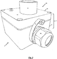
- Luftleitbauteils 1 which is connected on two sides in terms of flow with one tube 2, 3 of a pipe system, for example, a pipe system of an intake system for active fire detection and / or air monitoring.
- a pipe system for example, a pipe system of an intake system for active fire detection and / or air monitoring.
- a detection unit 4 for example by means of a suction unit (not shown).
- the sucked-in air flow is examined for fire characteristics, for example smoke particles or combustion gases, air quality parameters or the air composition.
- the air guiding component 1 is designed as a filter component in this and the following exemplary embodiments.
- the air guiding component 1 contains a filter insert 5 for prefiltering of coarse dirt particles from the air stream.
- the housing 7 of the air guide 1 in FIG. 1 an integral and firmly connected to the housing 7 6 connection.
- the air guide 1 with an example in Fig. 9 shown maintenance / cleaning device 22 as an overpressure or vacuum source or a strigetti be connected so that there is a fluid connection between the maintenance / cleaning device 22 and the pipe system.
- the housing 7 of the air guiding component 1 has closable openings 8 for selectively inserting shut-off elements, for example, with a cover, not shown, in order to interrupt the fluid connection of the air guiding component 1 to the tube 2 or tube 3 or both tubes 2, 3 during the maintenance / cleaning work can.
- the shut-off are, for example, simple shut-off plates, which are optionally provided with a circumferential seal and This can cause a simple but reliable separation of the connection to the adjacent tube 2, 3.
- For introducing and holding the shut-off guides 9 are provided.
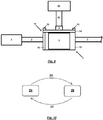
- FIG. 2 shows a second exemplary embodiment of the inventive air guiding component 1 with a designed as an adapter part first component 10, which is designed in this embodiment as a detachable housing cover for an air guide component 1.
- the air guiding component 1 comprises a housing 7, which consists of the mutually detachable components basic housing 13 and cover housing 14.
- the base housing 13 comprises a gas inlet 12a and a gas outlet 12b for connection to pipes 2, 3 of a pipe system, for example an intake system for active fire detection and / or air monitoring.
- the air guiding component 1 may additionally include, for example, a in FIG. 1 shown filter cartridge 5 included.
- the first component 10 embodied as an adapter part comprises the cover housing 14, a connection 6, connection means 15 and a permanently connected shut-off element 16.
- the cover housing 14 is designed to match the base housing 13 of the air-conducting component 1 and closes it when connecting the base housing 13 to the cover housing 14.
- the connection 6 is a passage in the cover housing 14 and, for example, with a thread for connecting the connection 6 with a maintenance / cleaning device 22 or with a leading to such maintenance / cleaning device 22, in Fig. 9 shown line 23 provided.
- the connecting means 15 serve the detachable connection of the cover housing 14 with the base housing 13 of the air guiding component 1 and are designed in this figure as screws.
- the shut-off element 16 is a shut-off plate fixedly connected to the cover housing 14, which blocks the fluid connection of the air-guiding component 1 to an adjacent tube.
- either the gas inlet 12a or the gas outlet 12b with the shut-off element 16 is closed.
- the fluid connection to a mechanically sensitive detection unit 4 can be interrupted during cleaning in order to protect the detection unit 4 from damage.
- FIGS. 3 to 5 show the second exemplary embodiment of the invention
- Luftleitbauteils 2 with a designed as an adapter part first component 10 and here as a quick release fasteners 15, which in contrast to in FIG. 2 shown variant a faster connection of the cover housing 14 of the adapter part designed as a first component 10 with the base housing 13 of the air guide 1 enable.
- This is done in place of the in FIG. 2 Screw connection shown a clamping connection between the cover housing 14 and Basic housing 13 used.
- the clamping connection is produced with here designed as a spring clip connecting means 15 which are each stretched between a projection of the cover housing 14 and a projection of the base housing 13.
- a protruding screw 17 is used as a projection of the cover housing 14 and a pipe connection 18 is used as a projection of the base housing 13.
- FIGS. 6 and 7 show the designed as an adapter part first component 10 with a designed as a spring clip quick release with dissolved connection to shipsleitbauteil 1.
- first component 10 shut-off 16 to see a circumferential seal 20, which is a reliable and dense Closure of the air guide component 1 against an adjacent pipe connection provides.
- FIGS. 8 and 9 serve the understanding of the inventive method for operating a in Fig. 12 shown fire detection and / or air monitoring system 39 in an in Fig. 10 shown normal operating mode 24 and in a maintenance / cleaning operating mode 26th
- FIG. 8th shows the fire detection and / or air monitoring system 39 in a normal operating mode 24 for fire detection or air monitoring.
- a stream of air is sucked out of a space to be monitored via pipes 2, 3 and fed to a detection unit 4 for analyzing the air flow for fire characteristics or air quality variables or the air composition.
- a between the tubes 2, 3 arranged air guide 1 is also traversed by the air flow.
- the air guiding component 1 is a filter component with a filter insert 5 for pre-filtering coarse dirt particles from the air stream.
- the housing 7 of the air-conducting component 1 comprises a base housing 13 and a second component 21 designed as a housing cover without connection, which are connected to one another by means of releasable connecting means 15, for example screws.
- FIG. 9 shows the fire detection and / or air monitoring system 39 in a maintenance / cleaning operating mode 26.
- the air guide 1 is connected to a designed as an adapter part first component 10 by the in FIG. 8th shown, designed as a housing cover second component 21 has been removed from the Lucasleitbauteil 1 and instead the cover housing 14 of the first component 10 was detachably connected by means of the connecting means 15 with the base housing 13 of the Lucasleitbauteils 1.
- the first component 10 has a connection 6, through which the air-conducting component 1 and the connected pipe 3 are fluidly connected via a line 23 to a maintenance / cleaning device 22, for example a vacuum cleaner.
- shut-off element 16 By means of the shut-off element 16 firmly connected to the first component 10, however, the connection of the air-conducting component 1 to the tube 2 which is connected to the detection unit 4 is blocked. As a result, the detection unit 4 is protected during the maintenance of the pipe system from damage caused by, for example, when cleaning strong negative pressure or pressure.
- FIG. 10 shows the inventive method as a state diagram.
- the normal operating mode 24 is an operating state of the fire detection and / or air monitoring system 39, in which it draws in an air flow from a space to be monitored and monitored by means of a detection unit 4, the air flow on fire characteristics, air quality parameters or air composition.
- the fire detection and / or air monitoring system 39 is in a maintenance state in which it is in particular cleaned, wherein, for example, the fluid connection to the detection unit 4 is interrupted.
- the transition 25 from the normal operating mode 24 to the maintenance / cleaning operating mode 26 is mainly through the establishment of a fluid connection between a maintenance / cleaning device 22 and a port 6 on an air guiding component 1 of the fire detection and / or air monitoring system 39 or between a maintenance - / Cleaning device 22, designed as an adapter part first component 10 with a terminal 6 and an air guide 1 of the fire detection and / or air monitoring system 39 characterized.
- a second component 21 of the air-conducting component 1 designed as a housing cover is released and the first component 10 designed as an adapter part is connected as a cover to a base housing 13 of the air-conducting component 1.
- the transition 27 from the maintenance / cleaning mode of operation 26 to the normal mode of operation 24 is primarily through the disconnection of a fluid connection between a service / cleaning device 22 and a port 6 on an air guiding component 1 of the fire detection and / or air monitoring system 39 or between maintenance Cleaning device 22, a designed as an adapter part first component 10 with a terminal 6 and an air guide 1 of the fire detection and / or air monitoring system 39.
- the first component 10 is released as a cover and connected as a housing cover second component 21 of the air guide 1 with a base housing 13 of the air guide 1.
- Fig. 11 shows an exemplary flowchart for performing the method according to the invention for servicing and / or cleaning a pipe system, in particular an aspirative fire detection and / or air monitoring system 39. The individual steps of the method will be described below.
- the process for servicing and / or cleaning the piping system is started, for example, due to the expiration of a maintenance interval, due to a fault message from the airflow monitor of the fire detection and / or air monitoring system 39 or, for example, after startup to test the fire detection and / or Air monitoring system 39 with a test gas.
- the air-conduction component 1 or the fire-detection and / or air-monitoring system 39 is already in a normal operating mode 24 before starting the process 28, in which it sucks in an airflow from a space to be monitored and with the aid of a detection unit 4 the airflow monitored for fire characteristics, air quality quantities or air composition.
- the steps 29, 30 and 31 serve to prepare the maintenance / cleaning step 32 and correspond to the transition 25 of the air guiding component 1 or the fire detection and / or air monitoring system 39 from a normal operating mode 24 in a maintenance / cleaning operating mode 26.
- the housing 7 of the air guiding component 1 is opened by a second component 29 designed as a housing cover being detached from the base housing 13 of the air guiding component 1 by loosening or removing the connecting means 15.
- the housing 7 of the air-conducting component 1 is closed by a first component 10 designed as an adapter part being placed on the base housing 13 of the air component 1 and fixed by means of the connecting means 15.
- a maintenance / cleaning device 22 For example, a compressed air source, a vacuum cleaner or a test gas source, via a line 23 to the terminal 6 of the adapter part designed as the first component 10 and thus fluidly connected to the housing interior of the Beerleitbauteils 1.
- step 32 the maintenance or cleaning is carried out, for example, by using the run as a compressed air source maintenance / cleaning device 22, the housing interior of the air guide 1 and the connected pipe 3 or pipe system are blown free, or by using for example by means of running as a vacuum cleaner maintenance / cleaning device 22, the housing interior of the air guiding component 1 and the connected pipe 3 or pipe system are sucked out, or by testing the fire detection and / or air monitoring system 39, for example, by means of the maintenance / cleaning device 22 designed as a test gas source.
- step 32 the air guiding component 1 or the fire detection and / or air monitoring system 39 is in a maintenance / cleaning mode 26 in which, for example, parts of the pipe system are fluidly separated from the air guiding component 1 by means of one or more blocking elements 16 and the air guiding component 1 is over a terminal 6 is connected to the maintenance / cleaning device 22.
- the step 32 is terminated when the maintenance or cleaning of the pipe system and / or the air guide 1 is completely completed.
- the steps 33, 34 and 35 correspond to the transition 27 of the air guiding component 1 or of the fire detection and / or air monitoring system 39 from a maintenance / cleaning operating mode 26 into a normal operating mode 24.
- the maintenance / cleaning device 22 for example a Compressed air source, a vacuum cleaner or a strigetti, separated from the terminal 6 of the designed as an adapter part first component 10 and thus separated from the housing interior of the air guide 1 fluidly.
- step 34 the housing 7 of the air guiding component 1 is opened, in that the first component 10 designed as an adapter part is released from the basic housing 13 of the air guiding component 1 by loosening or removing the connecting means 15.
- step 35 the housing 7 of the air-conducting component 1 is closed by the second component 21 designed as a housing cover being placed on the base housing 13 of the air-conducting component 1 and fixed by means of the connecting means 15. Since the second component 21 does not have a shut-off element, in this step a flow path extending from the gas inlet 12a to the gas outlet 12b is again formed in the interior of the housing 7, so that the pipe system connected to the air-conducting component 1 and the further components such as the detection unit 4 again fluidly with the Air guide 1 are connected.
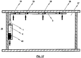
- FIG. 12 shows a schematic representation of a pipe system of an aspirative fire detection and / or air monitoring system 39, which is assigned to a monitoring area 37.
- Representative of the pipe system here is a single intake pipe 3 is shown.
- the tube 3 is mounted below the ceiling of the monitoring area 37, for example by means of pipe clamps.
- Intake openings 38 in the tube 3 suck air from the monitoring area 37.
- a suction unit 40 which is integrated in the fire detection and / or air monitoring system 39, is used.
- the suction unit 40 and the pipe system are monitored by an air flow sensor.
- a detection unit 4 which is designed, for example, as a smoke sensor or oxygen sensor, in the intake detector.
- the smoke sensor for example, uses scattered light measurements to examine the intake airflow to existing smoke particles.
- the oxygen sensor measures the oxygen concentration of the air sample, which represents an average of the oxygen concentration in the air of the monitoring area 37. The measured value is compared with threshold values in the fire detection and / or air monitoring system 39.
- the pipe system of the aspirative fire detection and / or air monitoring system 39 is associated with at least one inventive air guide 1, which may be, for example, a filter component.
- inventive air guide 1 may be, for example, a filter component.
Landscapes
- Engineering & Computer Science (AREA)
- Business, Economics & Management (AREA)
- Emergency Management (AREA)
- Mechanical Engineering (AREA)
- Chemical & Material Sciences (AREA)
- Health & Medical Sciences (AREA)
- Public Health (AREA)
- General Engineering & Computer Science (AREA)
- Combustion & Propulsion (AREA)
- Analytical Chemistry (AREA)
- Physics & Mathematics (AREA)
- General Physics & Mathematics (AREA)
- Fire-Detection Mechanisms (AREA)
- Filtering Of Dispersed Particles In Gases (AREA)
- Duct Arrangements (AREA)
Priority Applications (6)
| Application Number | Priority Date | Filing Date | Title |
|---|---|---|---|
| PL17020264T PL3327689T3 (pl) | 2016-11-25 | 2017-06-20 | Element filtrujący |
| PCT/IB2017/001396 WO2018146508A1 (fr) | 2016-11-25 | 2017-11-17 | Élément de guidage d'air |
| RU2019118968A RU2741477C2 (ru) | 2016-11-25 | 2017-11-17 | Воздухопроводящий конструктивный элемент |
| CN201780073048.7A CN110168623B (zh) | 2016-11-25 | 2017-11-17 | 空气引导构件 |
| AU2017397675A AU2017397675B2 (en) | 2016-11-25 | 2017-11-17 | Air-guiding component |
| US16/462,775 US11883698B2 (en) | 2016-11-25 | 2017-11-17 | Air-guiding component |
Applications Claiming Priority (1)
| Application Number | Priority Date | Filing Date | Title |
|---|---|---|---|
| DE102016014058 | 2016-11-25 |
Publications (2)
| Publication Number | Publication Date |
|---|---|
| EP3327689A1 true EP3327689A1 (fr) | 2018-05-30 |
| EP3327689B1 EP3327689B1 (fr) | 2020-10-14 |
Family
ID=59312946
Family Applications (1)
| Application Number | Title | Priority Date | Filing Date |
|---|---|---|---|
| EP17020264.2A Active EP3327689B1 (fr) | 2016-11-25 | 2017-06-20 | Élément filtrant |
Country Status (8)
| Country | Link |
|---|---|
| US (1) | US11883698B2 (fr) |
| EP (1) | EP3327689B1 (fr) |
| CN (1) | CN110168623B (fr) |
| AU (1) | AU2017397675B2 (fr) |
| ES (1) | ES2840775T3 (fr) |
| PL (1) | PL3327689T3 (fr) |
| RU (1) | RU2741477C2 (fr) |
| WO (1) | WO2018146508A1 (fr) |
Cited By (1)
| Publication number | Priority date | Publication date | Assignee | Title |
|---|---|---|---|---|
| CN117403767A (zh) * | 2023-11-28 | 2024-01-16 | 中国一冶集团有限公司 | 基于机器人的市政管道清淤装置及市政管道清淤方法 |
Families Citing this family (4)
| Publication number | Priority date | Publication date | Assignee | Title |
|---|---|---|---|---|
| US11327513B1 (en) * | 2021-05-18 | 2022-05-10 | Fisher Controls International Llc | Apparatus for managing pressure events in protective casings and related methods |
| US12436078B2 (en) * | 2022-08-10 | 2025-10-07 | Honeywell International Inc. | Aspirating smoke detector with test module |
| CN116453287B (zh) * | 2023-06-09 | 2023-08-15 | 广东创能科技股份有限公司 | 一种基于物联网的远程监控传感系统 |
| CN118097879B (zh) * | 2024-04-28 | 2024-07-05 | 贵州商学院 | 一种火灾烟雾探测报警装置及使用方法 |
Citations (6)
| Publication number | Priority date | Publication date | Assignee | Title |
|---|---|---|---|---|
| EP0025628A2 (fr) * | 1979-09-12 | 1981-03-25 | NoeL, MARQUET & CIE société anonyme: | Filtre à liquides à nettoyage automatique de l'élément filtrant |
| EP0341451A1 (fr) * | 1988-05-09 | 1989-11-15 | Siemens Aktiengesellschaft | Dispositif de filtre pour le courant d'échappement lors de dépôts chimiques en phase vapeur dans la technique des semi-conducteurs |
| DE202007006769U1 (de) * | 2007-05-08 | 2008-09-11 | Mann+Hummel Gmbh | Filter, insbesondere Luftfilter |
| DE202009018710U1 (de) * | 2009-10-09 | 2012-10-25 | Oliver Linden | Vorrichtung und Computerprogrammprodukt zur Projektierung eines Branderkennungssystems mit Absaugvorrichtung |
| DE102014011444A1 (de) * | 2013-09-02 | 2015-03-05 | Mann + Hummel Gmbh | Filterelement und Filtersystem mit einem Filterelement |
| EP2871620A1 (fr) * | 2013-11-07 | 2015-05-13 | Labor Strauss Sicherungsanlagenbau Ges. m. b. H | Agencement de détection de fumée |
Family Cites Families (15)
| Publication number | Priority date | Publication date | Assignee | Title |
|---|---|---|---|---|
| GB191516460A (en) * | 1915-11-22 | 1916-03-30 | Clayton And Shuttleworth Ltd | A Combined Filter and Plug Cock. |
| CN1020794C (zh) * | 1990-09-15 | 1993-05-19 | 浙江瑞安永久机电研究所 | 反冲过滤阀 |
| JP3257949B2 (ja) * | 1996-05-24 | 2002-02-18 | 日野自動車株式会社 | 排気黒煙除去装置のフィルタ再生機構 |
| DE29610900U1 (de) * | 1996-06-21 | 1997-10-16 | Taprogge GmbH, 58300 Wetter | Kugelschleuse für eine Einrichtung zum Rückführen von Kugeln zum Reinigen der Rohre von Kühlsystemen |
| DE19835733A1 (de) * | 1998-08-07 | 2000-02-17 | Reitter & Schefenacker Gmbh | Reinigungseinrichtung |
| DE10125687B4 (de) * | 2001-05-25 | 2005-06-16 | Wagner Alarm- Und Sicherungssysteme Gmbh | Vorrichtung zum Detektieren von Brandherden oder Gasverunreinigungen |
| DE10156042A1 (de) * | 2001-11-15 | 2003-05-28 | Wagner Alarm Sicherung | Verfahren und Vorrichtung zum Löschen von Bränden in Tunneln |
| CN2835850Y (zh) * | 2005-08-19 | 2006-11-08 | 李磊 | 一种油烟处理装置及其系统 |
| RU2368828C1 (ru) * | 2008-04-01 | 2009-09-27 | Закрытое Акционерное Общество "Новосибирскпродмаш" | Трехходовой кран (варианты) и устройство для ручного розлива пенящихся и/или газированных напитков в открытую тару с его использованием |
| KR100908464B1 (ko) * | 2008-10-06 | 2009-07-21 | 주식회사 근옥 | 실내공기 청정기 |
| FR2953734B1 (fr) * | 2009-12-15 | 2013-01-18 | Renault Sas | Filtre a particules recyclable |
| DE202011002009U1 (de) * | 2011-01-27 | 2012-04-30 | Hugo Vogelsang Maschinenbau Gmbh | Absaugkupplung |
| CN102606316B (zh) * | 2012-03-30 | 2014-05-07 | 冯子光 | 一种可变阀门排气管的控制装置 |
| CN204952467U (zh) * | 2015-08-21 | 2016-01-13 | 中国神华能源股份有限公司 | 过滤器滤芯的清洗箱 |
| KR101799090B1 (ko) * | 2015-11-24 | 2017-12-20 | 한대곤 | 공기정화장치 |
-
2017
- 2017-06-20 ES ES17020264T patent/ES2840775T3/es active Active
- 2017-06-20 PL PL17020264T patent/PL3327689T3/pl unknown
- 2017-06-20 EP EP17020264.2A patent/EP3327689B1/fr active Active
- 2017-11-17 US US16/462,775 patent/US11883698B2/en active Active
- 2017-11-17 AU AU2017397675A patent/AU2017397675B2/en active Active
- 2017-11-17 CN CN201780073048.7A patent/CN110168623B/zh active Active
- 2017-11-17 RU RU2019118968A patent/RU2741477C2/ru active
- 2017-11-17 WO PCT/IB2017/001396 patent/WO2018146508A1/fr not_active Ceased
Patent Citations (6)
| Publication number | Priority date | Publication date | Assignee | Title |
|---|---|---|---|---|
| EP0025628A2 (fr) * | 1979-09-12 | 1981-03-25 | NoeL, MARQUET & CIE société anonyme: | Filtre à liquides à nettoyage automatique de l'élément filtrant |
| EP0341451A1 (fr) * | 1988-05-09 | 1989-11-15 | Siemens Aktiengesellschaft | Dispositif de filtre pour le courant d'échappement lors de dépôts chimiques en phase vapeur dans la technique des semi-conducteurs |
| DE202007006769U1 (de) * | 2007-05-08 | 2008-09-11 | Mann+Hummel Gmbh | Filter, insbesondere Luftfilter |
| DE202009018710U1 (de) * | 2009-10-09 | 2012-10-25 | Oliver Linden | Vorrichtung und Computerprogrammprodukt zur Projektierung eines Branderkennungssystems mit Absaugvorrichtung |
| DE102014011444A1 (de) * | 2013-09-02 | 2015-03-05 | Mann + Hummel Gmbh | Filterelement und Filtersystem mit einem Filterelement |
| EP2871620A1 (fr) * | 2013-11-07 | 2015-05-13 | Labor Strauss Sicherungsanlagenbau Ges. m. b. H | Agencement de détection de fumée |
Non-Patent Citations (1)
| Title |
|---|
| WAGNER GROUP GMBH: "Air Sampling Smoke Detection System TITANUS TOP·SENS® /Rev.a", 30 April 2009 (2009-04-30), XP055435841, Retrieved from the Internet <URL:http://aguilera.es/documentacion/Detección%20Aspiración/Manuales/aett-manual-en.pdf> [retrieved on 20171218] * |
Cited By (1)
| Publication number | Priority date | Publication date | Assignee | Title |
|---|---|---|---|---|
| CN117403767A (zh) * | 2023-11-28 | 2024-01-16 | 中国一冶集团有限公司 | 基于机器人的市政管道清淤装置及市政管道清淤方法 |
Also Published As
| Publication number | Publication date |
|---|---|
| WO2018146508A1 (fr) | 2018-08-16 |
| PL3327689T3 (pl) | 2021-04-19 |
| RU2741477C2 (ru) | 2021-01-26 |
| CN110168623B (zh) | 2021-06-18 |
| CN110168623A (zh) | 2019-08-23 |
| US20200047011A1 (en) | 2020-02-13 |
| EP3327689B1 (fr) | 2020-10-14 |
| ES2840775T3 (es) | 2021-07-07 |
| RU2019118968A (ru) | 2020-12-25 |
| AU2017397675B2 (en) | 2022-06-30 |
| AU2017397675A1 (en) | 2019-07-04 |
| US11883698B2 (en) | 2024-01-30 |
| RU2019118968A3 (fr) | 2020-12-25 |
Similar Documents
| Publication | Publication Date | Title |
|---|---|---|
| EP3327689B1 (fr) | Élément filtrant | |
| DE3527732A1 (de) | Filtergeraet | |
| EP2871620B1 (fr) | Agencement de détection de fumée | |
| DE102008056514C5 (de) | Wägezelle und Verfahren zum Temperieren einer Wägezelle | |
| DE202008006811U1 (de) | Automatisches Freiblassystem für Rauchansaugsysteme im Brandschutz | |
| DE102010005960B4 (de) | Eine herausziehbare Staubsammelvorrichtung zum Einsetzen in einen Luftkanal | |
| EP1542188B1 (fr) | Dispositif et méthode pour détecter l'apparition d'un feu | |
| DE102005028632A1 (de) | Kondensatableiter mit Wartungsschnittstelle | |
| DE3921013C2 (de) | Meßanordnung zum Überwachen von Luftfilteranlagen | |
| DE29902638U1 (de) | Aspirative Branderkennungsvorrichtung | |
| DE202013100421U1 (de) | Ölnebelabscheider | |
| DE202023100333U1 (de) | Mobile Luftfilteranlage | |
| DE19815975A1 (de) | Schutzgehäuse für Beobachtungsgeräte | |
| DE19858877A1 (de) | Brandmelde- und Löscheinrichtung | |
| EP3215255B1 (fr) | Dispositif et procédé de séparation de matières condensables d'un flux d'air d'évacuation | |
| EP0909942A1 (fr) | Appareil pour l'aspiration d'un échantillon gazeux d'une enceinte de gaz industriel sous vide | |
| DE102012107249A1 (de) | Container mit Einrichtungen zur Zubereitung von Speisen | |
| DE29816225U1 (de) | Meßvorrichtung zur In-Situ-Funktionsprüfung eines Filters einer Filteranlage durch Bestimmung der Partikelanzahl in einer Gasprobe und Filteranlage zur Abscheidung von Partikeln aus einem Gasstrom | |
| DE102017100087B4 (de) | Einrichtung und Verfahren zum Warten von Asbest enthaltenden Brandschutzklappen | |
| DE19620252C2 (de) | Austauschbares Filterelement für Sicherheitswerkbänke in Krankenhäusern, Apotheken, Forschungslabors o. dgl. | |
| DE1940002C3 (de) | Filtergehäuse | |
| DE102017103945A1 (de) | Vorrichtung und Verfahren zum Austausch eines Gases aus einem Arbeitsraum eines begehbaren Inertgas-Gehäuses | |
| DE8907844U1 (de) | Meßanordnung zum Überwachen von Luftfilteranlagen | |
| EP4530610A1 (fr) | Appareil de base avec unité de détection de particules et filtres | |
| DE102017128854A1 (de) | Pneumatische Sämaschine |
Legal Events
| Date | Code | Title | Description |
|---|---|---|---|
| PUAI | Public reference made under article 153(3) epc to a published international application that has entered the european phase |
Free format text: ORIGINAL CODE: 0009012 |
|
| STAA | Information on the status of an ep patent application or granted ep patent |
Free format text: STATUS: THE APPLICATION HAS BEEN PUBLISHED |
|
| STAA | Information on the status of an ep patent application or granted ep patent |
Free format text: STATUS: REQUEST FOR EXAMINATION WAS MADE |
|
| AK | Designated contracting states |
Kind code of ref document: A1 Designated state(s): AL AT BE BG CH CY CZ DE DK EE ES FI FR GB GR HR HU IE IS IT LI LT LU LV MC MK MT NL NO PL PT RO RS SE SI SK SM TR |
|
| AX | Request for extension of the european patent |
Extension state: BA ME |
|
| 17P | Request for examination filed |
Effective date: 20180518 |
|
| RBV | Designated contracting states (corrected) |
Designated state(s): AL AT BE BG CH CY CZ DE DK EE ES FI FR GB GR HR HU IE IS IT LI LT LU LV MC MK MT NL NO PL PT RO RS SE SI SK SM TR |
|
| STAA | Information on the status of an ep patent application or granted ep patent |
Free format text: STATUS: EXAMINATION IS IN PROGRESS |
|
| 17Q | First examination report despatched |
Effective date: 20180920 |
|
| RIC1 | Information provided on ipc code assigned before grant |
Ipc: B01D 46/00 20060101AFI20190918BHEP Ipc: B08B 9/035 20060101ALI20190918BHEP Ipc: A62C 3/16 20060101ALN20190918BHEP Ipc: G08B 17/113 20060101ALI20190918BHEP Ipc: B08B 5/04 20060101ALN20190918BHEP Ipc: B08B 5/02 20060101ALN20190918BHEP Ipc: B08B 15/00 20060101ALI20190918BHEP Ipc: F24F 11/00 20180101ALI20190918BHEP |
|
| GRAP | Despatch of communication of intention to grant a patent |
Free format text: ORIGINAL CODE: EPIDOSNIGR1 |
|
| STAA | Information on the status of an ep patent application or granted ep patent |
Free format text: STATUS: GRANT OF PATENT IS INTENDED |
|
| RIC1 | Information provided on ipc code assigned before grant |
Ipc: A62C 3/16 20060101ALN20190920BHEP Ipc: G08B 17/113 20060101ALI20190920BHEP Ipc: B08B 5/04 20060101ALN20190920BHEP Ipc: B08B 9/035 20060101ALI20190920BHEP Ipc: B08B 5/02 20060101ALN20190920BHEP Ipc: B01D 46/00 20060101AFI20190920BHEP Ipc: B08B 15/00 20060101ALI20190920BHEP Ipc: F24F 11/00 20180101ALI20190920BHEP |
|
| INTG | Intention to grant announced |
Effective date: 20191025 |
|
| GRAJ | Information related to disapproval of communication of intention to grant by the applicant or resumption of examination proceedings by the epo deleted |
Free format text: ORIGINAL CODE: EPIDOSDIGR1 |
|
| STAA | Information on the status of an ep patent application or granted ep patent |
Free format text: STATUS: EXAMINATION IS IN PROGRESS |
|
| INTC | Intention to grant announced (deleted) | ||
| RIC1 | Information provided on ipc code assigned before grant |
Ipc: B01D 46/00 20060101AFI20200305BHEP Ipc: B08B 5/04 20060101ALN20200305BHEP Ipc: G08B 17/113 20060101ALI20200305BHEP Ipc: B08B 5/02 20060101ALN20200305BHEP Ipc: B08B 15/00 20060101ALI20200305BHEP Ipc: F24F 11/00 20180101ALI20200305BHEP Ipc: A62C 3/16 20060101ALN20200305BHEP Ipc: B08B 9/035 20060101ALI20200305BHEP |
|
| REG | Reference to a national code |
Ref country code: DE Ref legal event code: R079 Ref document number: 502017007700 Country of ref document: DE Free format text: PREVIOUS MAIN CLASS: G08B0017113000 Ipc: B01D0046000000 |
|
| GRAP | Despatch of communication of intention to grant a patent |
Free format text: ORIGINAL CODE: EPIDOSNIGR1 |
|
| STAA | Information on the status of an ep patent application or granted ep patent |
Free format text: STATUS: GRANT OF PATENT IS INTENDED |
|
| RIC1 | Information provided on ipc code assigned before grant |
Ipc: B01D 46/00 20060101AFI20200414BHEP Ipc: A62C 3/16 20060101ALN20200414BHEP Ipc: F24F 11/00 20180101ALI20200414BHEP Ipc: B08B 15/00 20060101ALI20200414BHEP Ipc: B08B 9/035 20060101ALI20200414BHEP Ipc: G08B 17/113 20060101ALI20200414BHEP Ipc: B08B 5/04 20060101ALN20200414BHEP Ipc: B08B 5/02 20060101ALN20200414BHEP |
|
| INTG | Intention to grant announced |
Effective date: 20200506 |
|
| GRAS | Grant fee paid |
Free format text: ORIGINAL CODE: EPIDOSNIGR3 |
|
| GRAA | (expected) grant |
Free format text: ORIGINAL CODE: 0009210 |
|
| STAA | Information on the status of an ep patent application or granted ep patent |
Free format text: STATUS: THE PATENT HAS BEEN GRANTED |
|
| AK | Designated contracting states |
Kind code of ref document: B1 Designated state(s): AL AT BE BG CH CY CZ DE DK EE ES FI FR GB GR HR HU IE IS IT LI LT LU LV MC MK MT NL NO PL PT RO RS SE SI SK SM TR |
|
| REG | Reference to a national code |
Ref country code: GB Ref legal event code: FG4D Free format text: NOT ENGLISH |
|
| REG | Reference to a national code |
Ref country code: AT Ref legal event code: REF Ref document number: 1323033 Country of ref document: AT Kind code of ref document: T Effective date: 20201015 Ref country code: CH Ref legal event code: EP |
|
| REG | Reference to a national code |
Ref country code: DE Ref legal event code: R096 Ref document number: 502017007700 Country of ref document: DE |
|
| REG | Reference to a national code |
Ref country code: CH Ref legal event code: NV Representative=s name: DENNEMEYER AG, CH |
|
| REG | Reference to a national code |
Ref country code: IE Ref legal event code: FG4D Free format text: LANGUAGE OF EP DOCUMENT: GERMAN |
|
| REG | Reference to a national code |
Ref country code: NL Ref legal event code: FP |
|
| PG25 | Lapsed in a contracting state [announced via postgrant information from national office to epo] |
Ref country code: PT Free format text: LAPSE BECAUSE OF FAILURE TO SUBMIT A TRANSLATION OF THE DESCRIPTION OR TO PAY THE FEE WITHIN THE PRESCRIBED TIME-LIMIT Effective date: 20210215 Ref country code: RS Free format text: LAPSE BECAUSE OF FAILURE TO SUBMIT A TRANSLATION OF THE DESCRIPTION OR TO PAY THE FEE WITHIN THE PRESCRIBED TIME-LIMIT Effective date: 20201014 Ref country code: NO Free format text: LAPSE BECAUSE OF FAILURE TO SUBMIT A TRANSLATION OF THE DESCRIPTION OR TO PAY THE FEE WITHIN THE PRESCRIBED TIME-LIMIT Effective date: 20210114 Ref country code: FI Free format text: LAPSE BECAUSE OF FAILURE TO SUBMIT A TRANSLATION OF THE DESCRIPTION OR TO PAY THE FEE WITHIN THE PRESCRIBED TIME-LIMIT Effective date: 20201014 Ref country code: GR Free format text: LAPSE BECAUSE OF FAILURE TO SUBMIT A TRANSLATION OF THE DESCRIPTION OR TO PAY THE FEE WITHIN THE PRESCRIBED TIME-LIMIT Effective date: 20210115 |
|
| REG | Reference to a national code |
Ref country code: LT Ref legal event code: MG4D |
|
| PG25 | Lapsed in a contracting state [announced via postgrant information from national office to epo] |
Ref country code: SE Free format text: LAPSE BECAUSE OF FAILURE TO SUBMIT A TRANSLATION OF THE DESCRIPTION OR TO PAY THE FEE WITHIN THE PRESCRIBED TIME-LIMIT Effective date: 20201014 Ref country code: BG Free format text: LAPSE BECAUSE OF FAILURE TO SUBMIT A TRANSLATION OF THE DESCRIPTION OR TO PAY THE FEE WITHIN THE PRESCRIBED TIME-LIMIT Effective date: 20210114 Ref country code: LV Free format text: LAPSE BECAUSE OF FAILURE TO SUBMIT A TRANSLATION OF THE DESCRIPTION OR TO PAY THE FEE WITHIN THE PRESCRIBED TIME-LIMIT Effective date: 20201014 Ref country code: IS Free format text: LAPSE BECAUSE OF FAILURE TO SUBMIT A TRANSLATION OF THE DESCRIPTION OR TO PAY THE FEE WITHIN THE PRESCRIBED TIME-LIMIT Effective date: 20210214 |
|
| PG25 | Lapsed in a contracting state [announced via postgrant information from national office to epo] |
Ref country code: HR Free format text: LAPSE BECAUSE OF FAILURE TO SUBMIT A TRANSLATION OF THE DESCRIPTION OR TO PAY THE FEE WITHIN THE PRESCRIBED TIME-LIMIT Effective date: 20201014 |
|
| REG | Reference to a national code |
Ref country code: ES Ref legal event code: FG2A Ref document number: 2840775 Country of ref document: ES Kind code of ref document: T3 Effective date: 20210707 |
|
| REG | Reference to a national code |
Ref country code: DE Ref legal event code: R097 Ref document number: 502017007700 Country of ref document: DE |
|
| PG25 | Lapsed in a contracting state [announced via postgrant information from national office to epo] |
Ref country code: LT Free format text: LAPSE BECAUSE OF FAILURE TO SUBMIT A TRANSLATION OF THE DESCRIPTION OR TO PAY THE FEE WITHIN THE PRESCRIBED TIME-LIMIT Effective date: 20201014 Ref country code: SM Free format text: LAPSE BECAUSE OF FAILURE TO SUBMIT A TRANSLATION OF THE DESCRIPTION OR TO PAY THE FEE WITHIN THE PRESCRIBED TIME-LIMIT Effective date: 20201014 Ref country code: CZ Free format text: LAPSE BECAUSE OF FAILURE TO SUBMIT A TRANSLATION OF THE DESCRIPTION OR TO PAY THE FEE WITHIN THE PRESCRIBED TIME-LIMIT Effective date: 20201014 Ref country code: EE Free format text: LAPSE BECAUSE OF FAILURE TO SUBMIT A TRANSLATION OF THE DESCRIPTION OR TO PAY THE FEE WITHIN THE PRESCRIBED TIME-LIMIT Effective date: 20201014 Ref country code: SK Free format text: LAPSE BECAUSE OF FAILURE TO SUBMIT A TRANSLATION OF THE DESCRIPTION OR TO PAY THE FEE WITHIN THE PRESCRIBED TIME-LIMIT Effective date: 20201014 Ref country code: RO Free format text: LAPSE BECAUSE OF FAILURE TO SUBMIT A TRANSLATION OF THE DESCRIPTION OR TO PAY THE FEE WITHIN THE PRESCRIBED TIME-LIMIT Effective date: 20201014 |
|
| PLBE | No opposition filed within time limit |
Free format text: ORIGINAL CODE: 0009261 |
|
| STAA | Information on the status of an ep patent application or granted ep patent |
Free format text: STATUS: NO OPPOSITION FILED WITHIN TIME LIMIT |
|
| PG25 | Lapsed in a contracting state [announced via postgrant information from national office to epo] |
Ref country code: DK Free format text: LAPSE BECAUSE OF FAILURE TO SUBMIT A TRANSLATION OF THE DESCRIPTION OR TO PAY THE FEE WITHIN THE PRESCRIBED TIME-LIMIT Effective date: 20201014 |
|
| 26N | No opposition filed |
Effective date: 20210715 |
|
| PG25 | Lapsed in a contracting state [announced via postgrant information from national office to epo] |
Ref country code: AL Free format text: LAPSE BECAUSE OF FAILURE TO SUBMIT A TRANSLATION OF THE DESCRIPTION OR TO PAY THE FEE WITHIN THE PRESCRIBED TIME-LIMIT Effective date: 20201014 |
|
| PG25 | Lapsed in a contracting state [announced via postgrant information from national office to epo] |
Ref country code: SI Free format text: LAPSE BECAUSE OF FAILURE TO SUBMIT A TRANSLATION OF THE DESCRIPTION OR TO PAY THE FEE WITHIN THE PRESCRIBED TIME-LIMIT Effective date: 20201014 |
|
| PG25 | Lapsed in a contracting state [announced via postgrant information from national office to epo] |
Ref country code: MC Free format text: LAPSE BECAUSE OF FAILURE TO SUBMIT A TRANSLATION OF THE DESCRIPTION OR TO PAY THE FEE WITHIN THE PRESCRIBED TIME-LIMIT Effective date: 20201014 |
|
| PG25 | Lapsed in a contracting state [announced via postgrant information from national office to epo] |
Ref country code: LU Free format text: LAPSE BECAUSE OF NON-PAYMENT OF DUE FEES Effective date: 20210620 |
|
| PG25 | Lapsed in a contracting state [announced via postgrant information from national office to epo] |
Ref country code: IE Free format text: LAPSE BECAUSE OF NON-PAYMENT OF DUE FEES Effective date: 20210620 |
|
| PG25 | Lapsed in a contracting state [announced via postgrant information from national office to epo] |
Ref country code: IS Free format text: LAPSE BECAUSE OF FAILURE TO SUBMIT A TRANSLATION OF THE DESCRIPTION OR TO PAY THE FEE WITHIN THE PRESCRIBED TIME-LIMIT Effective date: 20210214 |
|
| PG25 | Lapsed in a contracting state [announced via postgrant information from national office to epo] |
Ref country code: CY Free format text: LAPSE BECAUSE OF FAILURE TO SUBMIT A TRANSLATION OF THE DESCRIPTION OR TO PAY THE FEE WITHIN THE PRESCRIBED TIME-LIMIT Effective date: 20201014 |
|
| P01 | Opt-out of the competence of the unified patent court (upc) registered |
Effective date: 20230526 |
|
| PG25 | Lapsed in a contracting state [announced via postgrant information from national office to epo] |
Ref country code: HU Free format text: LAPSE BECAUSE OF FAILURE TO SUBMIT A TRANSLATION OF THE DESCRIPTION OR TO PAY THE FEE WITHIN THE PRESCRIBED TIME-LIMIT; INVALID AB INITIO Effective date: 20170620 |
|
| PG25 | Lapsed in a contracting state [announced via postgrant information from national office to epo] |
Ref country code: MK Free format text: LAPSE BECAUSE OF FAILURE TO SUBMIT A TRANSLATION OF THE DESCRIPTION OR TO PAY THE FEE WITHIN THE PRESCRIBED TIME-LIMIT Effective date: 20201014 |
|
| PG25 | Lapsed in a contracting state [announced via postgrant information from national office to epo] |
Ref country code: TR Free format text: LAPSE BECAUSE OF FAILURE TO SUBMIT A TRANSLATION OF THE DESCRIPTION OR TO PAY THE FEE WITHIN THE PRESCRIBED TIME-LIMIT Effective date: 20201014 |
|
| PGFP | Annual fee paid to national office [announced via postgrant information from national office to epo] |
Ref country code: GB Payment date: 20240621 Year of fee payment: 8 |
|
| PGFP | Annual fee paid to national office [announced via postgrant information from national office to epo] |
Ref country code: NL Payment date: 20240619 Year of fee payment: 8 |
|
| PGFP | Annual fee paid to national office [announced via postgrant information from national office to epo] |
Ref country code: AT Payment date: 20240620 Year of fee payment: 8 |
|
| PGFP | Annual fee paid to national office [announced via postgrant information from national office to epo] |
Ref country code: FR Payment date: 20240628 Year of fee payment: 8 |
|
| PGFP | Annual fee paid to national office [announced via postgrant information from national office to epo] |
Ref country code: PL Payment date: 20240607 Year of fee payment: 8 |
|
| PGFP | Annual fee paid to national office [announced via postgrant information from national office to epo] |
Ref country code: BE Payment date: 20240619 Year of fee payment: 8 |
|
| PG25 | Lapsed in a contracting state [announced via postgrant information from national office to epo] |
Ref country code: MT Free format text: LAPSE BECAUSE OF FAILURE TO SUBMIT A TRANSLATION OF THE DESCRIPTION OR TO PAY THE FEE WITHIN THE PRESCRIBED TIME-LIMIT Effective date: 20201014 |
|
| PGFP | Annual fee paid to national office [announced via postgrant information from national office to epo] |
Ref country code: IT Payment date: 20240625 Year of fee payment: 8 |
|
| PGFP | Annual fee paid to national office [announced via postgrant information from national office to epo] |
Ref country code: CH Payment date: 20240701 Year of fee payment: 8 Ref country code: ES Payment date: 20240731 Year of fee payment: 8 |
|
| PGFP | Annual fee paid to national office [announced via postgrant information from national office to epo] |
Ref country code: DE Payment date: 20250618 Year of fee payment: 9 |
|
| REG | Reference to a national code |
Ref country code: CH Ref legal event code: H13 Free format text: ST27 STATUS EVENT CODE: U-0-0-H10-H13 (AS PROVIDED BY THE NATIONAL OFFICE) Effective date: 20260127 |
|
| REG | Reference to a national code |
Ref country code: NL Ref legal event code: MM Effective date: 20250701 |
|
| REG | Reference to a national code |
Ref country code: AT Ref legal event code: MM01 Ref document number: 1323033 Country of ref document: AT Kind code of ref document: T Effective date: 20250620 |
|
| GBPC | Gb: european patent ceased through non-payment of renewal fee |
Effective date: 20250620 |
|
| REG | Reference to a national code |
Ref country code: BE Ref legal event code: MM Effective date: 20250630 |
|
| PG25 | Lapsed in a contracting state [announced via postgrant information from national office to epo] |
Ref country code: NL Free format text: LAPSE BECAUSE OF NON-PAYMENT OF DUE FEES Effective date: 20250701 |
|
| PG25 | Lapsed in a contracting state [announced via postgrant information from national office to epo] |
Ref country code: GB Free format text: LAPSE BECAUSE OF NON-PAYMENT OF DUE FEES Effective date: 20250620 |
|
| PG25 | Lapsed in a contracting state [announced via postgrant information from national office to epo] |
Ref country code: AT Free format text: LAPSE BECAUSE OF NON-PAYMENT OF DUE FEES Effective date: 20250620 |
|
| PG25 | Lapsed in a contracting state [announced via postgrant information from national office to epo] |
Ref country code: BE Free format text: LAPSE BECAUSE OF NON-PAYMENT OF DUE FEES Effective date: 20250630 Ref country code: IT Free format text: LAPSE BECAUSE OF NON-PAYMENT OF DUE FEES Effective date: 20250620 |
|
| PG25 | Lapsed in a contracting state [announced via postgrant information from national office to epo] |
Ref country code: FR Free format text: LAPSE BECAUSE OF NON-PAYMENT OF DUE FEES Effective date: 20250630 |