EP3327996B1 - Procédé et récepteur de détection de congestion - Google Patents
Procédé et récepteur de détection de congestion Download PDFInfo
- Publication number
- EP3327996B1 EP3327996B1 EP17203405.0A EP17203405A EP3327996B1 EP 3327996 B1 EP3327996 B1 EP 3327996B1 EP 17203405 A EP17203405 A EP 17203405A EP 3327996 B1 EP3327996 B1 EP 3327996B1
- Authority
- EP
- European Patent Office
- Prior art keywords
- clock rate
- receiver
- transmission clock
- packets
- bitrate
- Prior art date
- Legal status (The legal status is an assumption and is not a legal conclusion. Google has not performed a legal analysis and makes no representation as to the accuracy of the status listed.)
- Active
Links
Images


Classifications
-
- H—ELECTRICITY
- H04—ELECTRIC COMMUNICATION TECHNIQUE
- H04L—TRANSMISSION OF DIGITAL INFORMATION, e.g. TELEGRAPHIC COMMUNICATION
- H04L47/00—Traffic control in data switching networks
- H04L47/10—Flow control; Congestion control
- H04L47/11—Identifying congestion
-
- H—ELECTRICITY
- H04—ELECTRIC COMMUNICATION TECHNIQUE
- H04L—TRANSMISSION OF DIGITAL INFORMATION, e.g. TELEGRAPHIC COMMUNICATION
- H04L43/00—Arrangements for monitoring or testing data switching networks
- H04L43/08—Monitoring or testing based on specific metrics, e.g. QoS, energy consumption or environmental parameters
- H04L43/0876—Network utilisation, e.g. volume of load or congestion level
-
- H—ELECTRICITY
- H04—ELECTRIC COMMUNICATION TECHNIQUE
- H04L—TRANSMISSION OF DIGITAL INFORMATION, e.g. TELEGRAPHIC COMMUNICATION
- H04L43/00—Arrangements for monitoring or testing data switching networks
- H04L43/10—Active monitoring, e.g. heartbeat, ping or trace-route
- H04L43/106—Active monitoring, e.g. heartbeat, ping or trace-route using time related information in packets, e.g. by adding timestamps
-
- H—ELECTRICITY
- H04—ELECTRIC COMMUNICATION TECHNIQUE
- H04L—TRANSMISSION OF DIGITAL INFORMATION, e.g. TELEGRAPHIC COMMUNICATION
- H04L47/00—Traffic control in data switching networks
- H04L47/10—Flow control; Congestion control
- H04L47/25—Flow control; Congestion control with rate being modified by the source upon detecting a change of network conditions
-
- H—ELECTRICITY
- H04—ELECTRIC COMMUNICATION TECHNIQUE
- H04L—TRANSMISSION OF DIGITAL INFORMATION, e.g. TELEGRAPHIC COMMUNICATION
- H04L47/00—Traffic control in data switching networks
- H04L47/10—Flow control; Congestion control
- H04L47/28—Flow control; Congestion control in relation to timing considerations
- H04L47/283—Flow control; Congestion control in relation to timing considerations in response to processing delays, e.g. caused by jitter or round trip time [RTT]
-
- H—ELECTRICITY
- H04—ELECTRIC COMMUNICATION TECHNIQUE
- H04L—TRANSMISSION OF DIGITAL INFORMATION, e.g. TELEGRAPHIC COMMUNICATION
- H04L43/00—Arrangements for monitoring or testing data switching networks
- H04L43/16—Threshold monitoring
Definitions
- the present disclosure relates to the field of packet communications, and in particular to a receiver-based method for adapting the bitrate of a realtime media transmission to available network bandwidth based on network congestion detection.
- Voice over IP Internet Protocol
- IP networks such as the internet.
- Similar technologies can be used to transmit video streams.
- the audio and/or video streams are transmitted as packets using a transport layer protocol such as RTP (realtime transport protocol), and may pass through various transmission mediums, such as wired or wireless connections, and through network hardware such as routers.
- RTP realtime transport protocol
- Network congestion occurs when one or more elements in the network, such as one or more routers, receive a higher bitrate than they are capable of handling. This leads to packets being queued then dropped, and degrading the quality of the transmitted audio and/or video stream. Once network congestion has been identified, a solution for improving performance is to reduce the packet transmission bitrate over the network, thereby reducing packet loss.
- French patent application published as FR2899049 relates to a synchronisation source for transmitting synchronisation information by a packet network.
- T k is the clock used to generate the timestamp
- Oe is an estimate of an origin value of the timestamps
- the reception time t k is predicted using an adaptive filtering technique based on a recursive least squares algorithm or on a Kalman filter algorithm; comparing the estimated transmission clock rate with a threshold; and detecting congestion in the network based on said comparison.
- estimating the transmission clock rate is performed in response to the reception of each packet of the media stream received by the receiver.
- the threshold is a fixed level.
- the threshold is calculated based on an average of a plurality of previous estimates of the transmission clock rate.
- the method further comprises, in response to detecting congestion: estimating available bandwidth based on at least a detected bitrate of the media stream; and transmitting a first bitrate limitation request to a transmitter transmitting the media stream to request that the transmission bitrate is reduced.
- the first bitrate limitation request is to reduce the bitrate to a level of between 15 and 40 percent lower than the estimated available bandwidth.
- the method further comprises: calculating, by the receiver, a new estimate of the transmission clock rate based on one or more further packets received after transmission of the first bitrate limitation request; and determining from the new estimate that the network is no longer congested, and in response transmitting to the transmitter a second bitrate limitation request.
- the second bitrate limitation request is to increase the bitrate to a level of between 2 and 10 percent lower than the estimated available bandwidth.
- T k is the clock used to generate the timestamp
- Oe is an estimate of an origin value of the timestamps
- the reception time t k is predicted using an adaptive filtering technique based on a recursive least squares algorithm or on a Kalman filter algorithm; compare the estimated transmission clock rate with a threshold; and detect congestion in the network based on said comparison.
- example embodiments are described based on packet transmission using RTP Realtime Transport Protocol), for example defined in the standard IETF RFC3550. However, it will be apparent to those skilled in the art that the techniques described herein could be applied to other packet transmission protocols.
- the term "around" is used herein to designate a range of +/- 10 percent of the value in question.
- FIG. 1 schematically illustrates a packet transmission system 100 according to an example embodiment.
- the system 100 comprises a transmitter (TRANSMITTER) 102 and a receiver (RECEIVER) 104 coupled via a network (NETWORK) 106 represented by a cloud.
- the transmitter 102 is capable of transmitting an audio and/or video stream to the receiver 104 via the network 106.
- the term "media stream" will be used to designate a stream comprising packets of audio and/or video data.
- the transmitter 102 may also be capable of receiving a media stream from the receiver 104, but for ease of description, communications in only one direction will be described herein.
- the transmitter 102 and receiver 104 are each for example communications devices, such as mobile telephones, smart phones, tablet or laptop computers, or the like, adapted to communicate with the network 106 via one or more wired or wireless links.
- each of the transmitter 102 and receiver 104 could be a laptop computer or personal computer (PC) coupled to the network 106 via a wired network such as a LAN (local area network) or via a wireless network such as a wireless LAN.
- a wired network such as a LAN (local area network) or via a wireless network such as a wireless LAN.
- the network 106 is for example a packet-switched network, for example comprising the internet, and includes routers for directing packets through the network, as known by those skilled in the art.
- the transmitter 102 is adapted to transmit the media stream to the receiver 104 in the form of packets using a transport layer protocol such as RTP.
- the effective transmission bitrate in other words the rate at which data is successfully transmitted over the network, is a function of the transmission bitrate, the latency between the end points, and the packet loss rate.
- FIG. 2 schematically illustrates part of the receiver 104 of Figure 1 in more detail according to an example embodiment.
- the receiver 104 for example comprises an input interface (I/P) 202 for receiving packets from the network 106, and for providing suitable demodulation and conversion, depending on the particular transmission interface via which the packets are received.
- I/P input interface
- An output of the input interface 202 is coupled to a timing analysis module (TIMING ANALYSIS) 204, which for example provides estimates Re of a transmission clock rate of the transmitted data, as described in more detail below.
- the transmission clock rate for example corresponds to the rate at which a timestamp of each packet is incremented.
- the transmission clock rate is thus not the same as the transmission bitrate, the latter being a measure of the quantity of data transmitted by the receiver during a given period, which can for example be adjusted by varying the level of compression of the audio or video stream.
- the module 204 also provides estimates Oe of an origin of timestamps of the data packets.
- the module 204 for example comprises a buffer (BUFFER) 205 for buffering the received data packets.
- BUFFER buffer
- Each data packet for example comprises a header including a timestamp, which is for example an RTP timestamp.
- the RTP protocol is for example described in more detail in the publication by H. Schulzrinne et al. entitled “RTP: A Transport Protocol for Real-Time Applications", the internet society (2003 ), the contents of which is for example incorporated herein to the extent permitted by the law.
- the timestamp is for example a 32 bit value, and for example indicates the value of the RTP clock at the sampling instant of a first sample in the RTP data packet.
- O is the origin of the timestamps, which is for example initiated at a random value, and is then constant during a given media transmission
- R is the transmission clock rate, for example equal to the RTP clock rate associated with the media stream
- t is the media time, for example corresponding to the clock count of the transmitter 102, or the system time used during the generation of video packets.
- the RTP clock rate, and thus the transmission clock rate, for a video stream defined in 1/90 000 of a second, and for an audio stream is equal to the audio sampling rate, which is for example equal to 8 kHz, although many other values would be possible.
- a first packet of an audio stream could have a timestamp equal to the origin O, and may contain 160 samples.
- a subsequent packet of the audio stream would then have a timestamp equal to O+160.
- the receiver 104 is generally distant from the transmitter 102, and may not be precisely synchronized by external mechanisms such as the NTP (network time protocol) or by a GPS (global positioning system) device.
- the time reference used for the transmission is the one employed by the sampling device, such as the analog to digital converter of the transmitter 102, whose actual sampling rate may differ slightly, as a result of hardware manufacturing constraints, from the sampling rate of the rendering device, such as the digital to analog converter of the receiver 104. This results in clock skew between the transmitter 102 and the receiver 104, which is generally under five percent, but which should generally be taken into account by the receiver 104 in order to ensure correct playback.
- the timing analysis module 204 is configured to estimate the transmission clock rate Re based on timing data associated with one or more received packets. For example, the timing analysis module estimates the transmission clock rate Re based on the local media time t at the receiver 104, and the timestamp of a plurality of received packets. As one example not covered by the appended claims, a relatively approximate estimation could be achieved based on a packet having a timestamp T1 received at a time t1 and a packet having a timestamp T2 received at a time t2, by computing (T1-T2)/(t1-t2). The timing analysis module 204 for example assumes a linear relationship between the local receiver media time t and the timestamps of the received packets.
- the values of Re and Oe are for example updated in response to the reception of each new packet. Furthermore, so that the transmission clock rate estimates fall significantly when network congestion occurs, the calculation of the estimate for example involves a "forgetting factor", such that the timing data associated with older packets is either not considered or it is given less weight. For example, the estimate is calculated based on the timing data of a limited number of the latest packets received. Alternatively, calculating the estimate involves weighting timing data associated with more recent packets with a higher weight than the timing data associated with older packets.
- the transmission clock rate estimate is an estimate Re of the transmission clock rate at the transmitter
- the transmission clock rate estimate is represented in the form of a ratio Ce between the clock rates of the transmission and reception clocks.
- An example of a method of estimating the ratio Ce between the clock rates of the transmission and reception clocks will be described in more detail below with reference to Figure 4 .
- the data packets are for example provided from the module 204 to a decoder (DECODER) 206.
- the decoder 206 decodes, using a system clock (SYSTEM CLK), the audio and/or video packets based on the particular audio and/or video compression standard applied to the media stream, and generates a decoded audio and/or video stream.
- SYSTEM CLK system clock
- the audio stream is processed by a sound card (SOUND CARD) .
- the timing analysis module 204 for example provides the estimates Re of the transmission clock rate of the packets to a rate control circuit (RATE CONTROL) 208.
- RATE CONTROL rate control circuit
- the rate control circuit 208 is for example adapted to detect when congestion occurs in the network based at least on the estimates Re. In some embodiments, if network congestion is detected, the rate control circuit 208 is adapted to generate and transmit to the transmitter 102, via an output interface (O/P) 210, one or more bitrate requests (REQ) defining a maximum transmission bitrate to be used for the transmission of future packets in order to stop the congestion. For example, the request is for the transmitter to reduce its maximum transmission bitrate by between 5 and 50 percent.
- REQ bitrate requests
- timing analysis module 204 the decoder 206, and the rate control circuit 208 have been illustrated as separate hardware circuits in Figure 2 , it will be apparent to those skilled in the art that one or more of these blocks could be implemented in software by instructions executed by a processing device.
- FIG 3 schematically illustrates the transmitter 102 of Figure 1 in more detail according to an example embodiment.
- the transmitter 102 for example comprises an encoder (ENCODER) 302, which receives an audio and/or video stream (AUDIO AND/OR VIDEO).
- the audio and/or video streams may be captured by a microphone and/or video camera of or coupled to the transmitter 102 (not illustrated in the figures).
- the encoder 302 for example encodes the audio and/or video streams to generate media packets P.
- the media packets P are for example provided to a transmission interface (TRANSMISSION INTERFACE) 304, which transmits the media packets to the receiver 104 of Figure 1 .
- a transmission interface (TRANSMISSION INTERFACE) 304, which transmits the media packets to the receiver 104 of Figure 1 .
- the encoder 302 for example receives the request signal (REQ) from the receiver indicating a maximum transmission bitrate to be used for the encoded audio and/or video streams, and adjusts the bitrate accordingly. For example, in the case of an audio stream, the encoder 302 decreases the transmission bitrate by applying a stronger compression to the raw audio stream, and increases the transmission bitrate by applying a weaker compression to the raw audio stream.
- the encoder 302 uses a variable bitrate audio codec, such as the Opus codec, standardized by the Internet Engineering Task Force (IETF) as RFC 6716, or the AMR (adaptive multi rate) codec based on the ITU (international telecommunication union) standard.
- the encoder 302 for example adjusts the transmission bitrate by modifying the quality factor applied during the video encoding, or by increasing or decreasing the frame rate and/or the image resolution.
- Figure 4 is a flow diagram representing operations in a method of estimating the origin Oe of the timestamps and clock rate ratio Ce between the transmission and reception clock rates according to an example embodiment. These operations are for example performed by a processing device of the timing analysis circuit 204.
- the ratio Ce for example corresponds to Re/Trec, where Trec is the clock rate at the receiver.
- an operation 401 it is determined whether a new packet has been received.
- operations 402 to 404 are performed to estimate the parameters Ce and Oe.
- This method is for example an iterative method, each iteration corresponding to a new packet. The method converges to relatively precise estimates of Ce and Oe after several iterations.
- the estimation of the parameters Ce and Oe for example uses an RLS algorithm based on the Kalman algorithm, applied to a model y(k) that assumes an ideal transmission.
- ⁇ is a forgetting factor of between 0 and 1
- P(k) is a gain matrix
- P(k) is a gain matrix
- K(k) is the Kalman matrix gain.
- a difference is calculated between the timestamp T k of the received packet and an estimation of the timestamp based on previous estimates of Ce and Oe, for example based on the formula: T k - ( Ce k -1 t k + Oe k -1 ) .
- Ce k Ce k ⁇ 1 + P 11 t k + P 12 T k ⁇ Ce k ⁇ 1 t k + Oe k ⁇ 1
- Oe k Oe k ⁇ 1 + P 21 t k + P 22 T k ⁇ Ce k ⁇ 1 t k + Oe k ⁇ 1
- P is the gain matrix, which is for example a two-by-two matrix having a top row of values P 11 and P 12 , and a bottom row of values P 21 and P 22 .
- a k ⁇ + ( P 11 t k + P 21 ) t k + ( P 12 t k + P 22 )
- ⁇ is a forgetting factor of between 0 and 1.
- the method then for example returns to operation 401 ready for the reception of a subsequent packet.
- the values of the parameters Ce and Oe, as well as of the gain matrix P, are for example initialized at the start of a given transmission of an audio and/or video stream.
- the value of Ce can be expected to be in the range [0.9-1.1] with a high level of confidence, as the transmission and reception clock rates should be calibrated relatively well with each other.
- the parameter Oe could however take any value, because the origin of the timestamps is chosen randomly by the emitter. It can therefore take several iterations in order for the value of Oe to settle to a relatively precise estimate.
- the forgetting factor ⁇ is for example set to a value of between 0.8 and 0.95, such that the estimate Ce shifts as network conditions change.
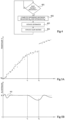
- Figure 5A is a graph illustrating, by dots, an example of the media time t that packets having timestamps T are received by the receiver in a case in which no congestion detection or correction is performed.
- a dashed curve in Figure 5A has a gradient representing the transmission clock rate estimates Re based on the reception time of the packets.
- Figure 5B is a graph showing a curve representing the estimates Re of the transmission clock rate based on the packets received in the example of Figure 5A .
- the gradient of the dashed curve in Figure 5A is relatively linear.
- the corresponding transmission clock rate estimates which are for example based on an estimation of the linear relationship between the time t and the received timestamps T, are also relatively stable following a few initial oscillations, and converge to a level 502 at or close to the true transmission clock rate R.
- the router in the network at which the network congestion occurs for example drops packets, leading to a discontinuity in the timestamps received. This for example causes the transmission clock rate estimates to increase again.
- the congestion in the network is still present, and thus the gradient of the dashed curve in Figure 5A remains low after the time t 2 , and the transmission clock rate estimates tail off again.
- the rate control circuit 208 of Figure 2 is for example adapted to detect when the transmission clock rate estimates Re drop significantly, for example to a level of less than a threshold TH.
- congestion is only detected when the estimates Re fall below the threshold TH for a minimum time duration Tc, where Tc is for example a duration of between 100 ms and 10 s.
- the threshold TH is a constant level based on a theoretical value of R.
- the threshold TH is equal to F*R theoretical , where R theoretical is a theoretical level of R, equal in one example to 8 KHz in the case of an audio stream, and F is a factor equal to less than 1, and for example equal to between 80 and 95 percent, corresponding to a factor of between 0.8 and 0.95.
- the threshold TH could be a dynamically changing threshold based on one or more previous estimates Re.
- Figure 6 is a flow diagram illustrating operations in a method of detecting and stopping congestion in a network.
- Figure 7 is a state diagram representing states of the rate control module 208 according to an example embodiment.
- the rate control module 208 is for example in a normal state (NORMAL) 702.
- NVMAL normal state
- a packet is for example received, which for example triggers a congestion detection process.
- the congestion detection process could be triggered in another fashion, for example periodically.
- an estimate Re of the transmission clock rate is for example calculated as described above, based for example on timing data associated with one or more received packets.
- the estimated transmission clock rate Re indicates the presence of congestion. For example, congestion is detected if the following condition holds for more than a minimum duration Tc: Re ⁇ F ⁇ R theoretical where, as mentioned above, F is a factor for example equal to between 0.80 and 0.95, and R theoretical is the theoretical transmission clock rate.
- bitrate request signal REQ is for example transmitted to the transmitting circuit 102.
- the bitrate request is based on the measured bandwidth Be of the communications channel between the transmitter 102 and receiver 104, which for example provides an estimate of the available bandwidth.
- the bandwidth Be is measured by calculating the bitrate of the media stream received by the receiver 104.
- the bitrate request is for example for a bitrate corresponding to between 15 and 40 percent less that the measured bandwidth Be, and for example at around 30 percent less than the measured bandwidth Be.
- a congestion present state (CONGESTION PRESENT) 708 of Figure 7 is then for example entered, and in this state, new congestion detection operations are for example performed.
- a new estimate Re of the transmission clock rate is for example calculated, and in an operation 607, it is determined whether congestion is present, for example based on the same test as applied in operation 603. This is represented by an arrow 710 in Figure 7 .
- the operations 606 and 607 are for example repeated until congestion is no longer detected. For example, congestion is no longer considered to be present if the value of Re is equal to or exceeds the threshold TH, for example if: Re ⁇ F ⁇ R theoretical
- the state then for example transitions to a congestion resolved state (CONGESTION RESOLVED) 712 in Figure 7 , and in an operation 608, a new bitrate request is for example transmitted to the transmitter 102 to increase the transmission bitrate with respect to the requested reduced bandwidth.
- the new bitrate request is based on the previously measured bandwidth Be, and is for example between 2 and 10 percent lower than the measured bandwidth Be, and for example 5 percent lower.
- the state then for example transitions back to the normal state 702 of Figure 7 , represented by the box 604 in Figure 6 .
- An advantage of initially requesting a large reduction in the transmission bitrate when congestion is detected is that this permits the congested router to recover by sending the pending packets that were previously buffered and which are causing the congestion. Once the receiver observes that the congestion has been resolved, the transmission bitrate can be increased to a level closer to available bandwidth estimated when congestion occurred.
- An advantage of the embodiments described herein is that, by using transmission clock rate estimates to detect the presence of network congestion, an effective and early warning system can be provided, permitting the congestion problem to be addressed before a high number of packets is dropped and the media stream quality becomes degraded.
Landscapes
- Engineering & Computer Science (AREA)
- Computer Networks & Wireless Communication (AREA)
- Signal Processing (AREA)
- Environmental & Geological Engineering (AREA)
- Health & Medical Sciences (AREA)
- Cardiology (AREA)
- General Health & Medical Sciences (AREA)
- Data Exchanges In Wide-Area Networks (AREA)
Claims (9)
- Procédé de détection de congestion dans un réseau à commutation par paquets (106), comprenant :l'estimation, par un récepteur (104), d'une cadence d'horloge de transmission, Re, d'un ou de plusieurs paquets du flux d'information reçu par le récepteur, chaque paquet comprenant un repère temporel généré sur la base de la cadence d'horloge de transmission, R, dans lequel la cadence d'horloge de transmission, Re, est estimée sur la base de la synchronisation d'une pluralité n de paquets reçus et de repères temporels associés auxdits n paquets et l'estimation de la cadence d'horloge de transmission, Re, comprend l'estimation d'un rapport de cadences d'horloge, Ce, entre la cadence d'horloge de transmission et la cadence d'horloge au niveau du récepteur sur la base du modèle suivant du temps de réception tk d'un paquet k :
 où Tk est le repère temporel, et Oe est une estimation d'une valeur d'origine des repères temporels, et le temps de réception tk est prédit en utilisant une technique de filtrage adaptatif sur la base d'un algorithme des moindres carrés récursifs, RLS, ou un algorithme de filtre de Kalman ;la comparaison de la cadence d'horloge de transmission estimée, Re, à un seuil, TH ; etla détection d'une congestion dans le réseau sur la base de ladite comparaison.
 - Procédé selon la revendication 1, dans lequel l'estimation de la cadence d'horloge de transmission est effectuée en réponse à la réception de chaque paquet du flux d'information reçu par le récepteur (104).
- Procédé selon la revendication 1 ou 2, dans lequel le seuil, TH, est un niveau fixé.
- Procédé selon la revendication 1 ou 2, dans lequel le seuil, TH, est calculé sur la base d'une moyenne d'une pluralité d'anciennes estimations, Re, de la cadence d'horloge de transmission.
- Procédé selon l'une quelconque des revendications 1 à 4, comprenant en outre, en réponse à la détection d'une congestion :l'estimation de la largeur de bande disponible, Be, sur la base d'au moins une des cadences binaires détectées du flux d'information ; etl'émission d'une première requête de limitation de cadence binaire, REQ, vers un émetteur (102) transmettant le flux d'information pour faire la requête d'une réduction de la cadence binaire de transmission.
- Procédé selon la revendication 5, dans lequel la première requête de limitation de cadence binaire est de réduire la cadence binaire jusqu'à un niveau compris entre 15 et 40 % de moins que la largeur de bande disponible estimée, Be.
- Procédé selon la revendication 5 ou 6, comprenant en outre :le calcul, par le récepteur (104), d'une nouvelle estimation de la cadence d'horloge de transmission sur la base d'un ou de plusieurs autres paquets ultérieurs reçus après la transmission de la première requête de limitation de cadence binaire ; etla détermination à partir de la nouvelle estimation que le réseau n'est plus congestionné, et la transmission en réponse vers l'émetteur (102) d'une deuxième requête de limitation de cadence binaire.
- Procédé selon la revendication 7, dans lequel la deuxième requête de limitation de cadence binaire est d'augmenter la cadence binaire à un niveau compris entre 2 et 10 % de moins que la largeur de bande disponible estimée, Be.
- Récepteur recevant un flux d'information transmis par un réseau à commutation par paquets (106), le récepteur étant configuré pour :estimer une cadence d'horloge de transmission, Re, d'un ou de plusieurs paquets d'un flux d'information reçu par le récepteur, chaque paquet comprenant un repère temporel généré sur la base de la cadence d'horloge de transmission (R), dans lequel la cadence d'horloge de transmission, Re, est estimé sur la base de la synchronisation d'une pluralité n de paquets reçus et de repères temporels associés auxdits n paquets et le récepteur est configuré pour estimer la cadence d'horloge de transmission, Re, en estimant un rapport de cadences d'horloge, Ce, entre la cadence d'horloge de transmission et la cadence d'horloge au niveau du récepteur sur la base du modèle suivant du temps de réception tk d'un paquet k :
 où Tk est le repère temporel, et Oe est une estimation d'une valeur d'origine des repères temporels, et le temps de réception tk est prédit en utilisant une technique de filtrage adaptatif sur la base d'un algorithme des moindres carrés récursifs, RLS, ou un algorithme de filtre de Kalman ;comparer la cadence d'horloge de transmission estimée, Re, à un seuil, TH ; etla détection d'une congestion dans le réseau sur la base de ladite comparaison.
Applications Claiming Priority (1)
| Application Number | Priority Date | Filing Date | Title |
|---|---|---|---|
| FR1661442A FR3059185B1 (fr) | 2016-11-24 | 2016-11-24 | Procede et circuit de dectection de congestion |
Publications (3)
| Publication Number | Publication Date |
|---|---|
| EP3327996A1 EP3327996A1 (fr) | 2018-05-30 |
| EP3327996B1 true EP3327996B1 (fr) | 2025-01-08 |
| EP3327996C0 EP3327996C0 (fr) | 2025-01-08 |
Family
ID=58314392
Family Applications (1)
| Application Number | Title | Priority Date | Filing Date |
|---|---|---|---|
| EP17203405.0A Active EP3327996B1 (fr) | 2016-11-24 | 2017-11-23 | Procédé et récepteur de détection de congestion |
Country Status (2)
| Country | Link |
|---|---|
| EP (1) | EP3327996B1 (fr) |
| FR (1) | FR3059185B1 (fr) |
Families Citing this family (1)
| Publication number | Priority date | Publication date | Assignee | Title |
|---|---|---|---|---|
| CN115378832B (zh) * | 2022-07-29 | 2024-03-26 | 北京奇艺世纪科技有限公司 | 拥塞检测方法、装置及流媒体传输系统、电子设备和介质 |
Citations (1)
| Publication number | Priority date | Publication date | Assignee | Title |
|---|---|---|---|---|
| US20070223459A1 (en) * | 2006-03-21 | 2007-09-27 | Zarlink Semiconductor Limited | Timing source |
Family Cites Families (1)
| Publication number | Priority date | Publication date | Assignee | Title |
|---|---|---|---|---|
| CN103238349B (zh) * | 2010-11-30 | 2016-08-10 | 瑞典爱立信有限公司 | 用于无线通信中的信道适配的方法和装置 |
-
2016
- 2016-11-24 FR FR1661442A patent/FR3059185B1/fr active Active
-
2017
- 2017-11-23 EP EP17203405.0A patent/EP3327996B1/fr active Active
Patent Citations (1)
| Publication number | Priority date | Publication date | Assignee | Title |
|---|---|---|---|---|
| US20070223459A1 (en) * | 2006-03-21 | 2007-09-27 | Zarlink Semiconductor Limited | Timing source |
Also Published As
| Publication number | Publication date |
|---|---|
| EP3327996A1 (fr) | 2018-05-30 |
| FR3059185B1 (fr) | 2018-12-07 |
| FR3059185A1 (fr) | 2018-05-25 |
| EP3327996C0 (fr) | 2025-01-08 |
Similar Documents
| Publication | Publication Date | Title |
|---|---|---|
| Johansson et al. | Self-clocked rate adaptation for multimedia | |
| US10805196B2 (en) | Packet loss and bandwidth coordination | |
| CN101971629B (zh) | 用于适配视频信号的目标速率的设备和方法 | |
| CN107624232B (zh) | 在通信系统中控制下行链路吞吐量的设备和方法 | |
| US7733773B2 (en) | Playout based delay scheduler | |
| EP3329641B1 (fr) | Surveillance des conditions réseau | |
| US7787500B2 (en) | Packet receiving method and device | |
| WO2017000719A1 (fr) | Procédé de contrôle de congestion et dispositif basé sur un retard de file d'attente | |
| CN105873096A (zh) | 一种多路径并行传输系统有效吞吐量的优化方法 | |
| PH12015501741B1 (en) | Voip bandwidth management | |
| CN106301684A (zh) | 一种媒体数据传输方法及装置 | |
| US8873590B2 (en) | Apparatus and method for correcting jitter | |
| US20150171992A1 (en) | Systems and Methods for Equalizing Retransmission Delays for Data Retransmission Over Bonded Modems | |
| EP3328010B1 (fr) | Mémoire tampon de gigue adaptative | |
| EP3202061B1 (fr) | Gestion de la profondeur d'un tampon de gigue | |
| EP3327996B1 (fr) | Procédé et récepteur de détection de congestion | |
| US10587518B2 (en) | Identifying network conditions | |
| CN114143271B (zh) | 一种基于拥塞检测的带宽估算方法及装置 | |
| US7715404B2 (en) | Method and apparatus for controlling a voice over internet protocol (VoIP) decoder with an adaptive jitter buffer | |
| WO2023207067A1 (fr) | Appareil d'envoi de données, appareil de réception de données, procédé de transmission de données et système de transmission de données | |
| CN116669002A (zh) | 用于蓝牙主设备数据传输的控制方法、蓝牙主设备及系统 | |
| CN116170376A (zh) | 数据传输控制方法、装置、设备及计算机存储介质 | |
| CN113411093B (zh) | 具有抗射频干扰机制的信号接收装置及方法 | |
| Johansson et al. | RFC 8298: Self-Clocked Rate Adaptation for Multimedia | |
| US20180278537A1 (en) | Data communication device, method for controlling data communication, and program |
Legal Events
| Date | Code | Title | Description |
|---|---|---|---|
| PUAI | Public reference made under article 153(3) epc to a published international application that has entered the european phase |
Free format text: ORIGINAL CODE: 0009012 |
|
| STAA | Information on the status of an ep patent application or granted ep patent |
Free format text: STATUS: THE APPLICATION HAS BEEN PUBLISHED |
|
| AK | Designated contracting states |
Kind code of ref document: A1 Designated state(s): AL AT BE BG CH CY CZ DE DK EE ES FI FR GB GR HR HU IE IS IT LI LT LU LV MC MK MT NL NO PL PT RO RS SE SI SK SM TR |
|
| AX | Request for extension of the european patent |
Extension state: BA ME |
|
| STAA | Information on the status of an ep patent application or granted ep patent |
Free format text: STATUS: REQUEST FOR EXAMINATION WAS MADE |
|
| 17P | Request for examination filed |
Effective date: 20180627 |
|
| RBV | Designated contracting states (corrected) |
Designated state(s): AL AT BE BG CH CY CZ DE DK EE ES FI FR GB GR HR HU IE IS IT LI LT LU LV MC MK MT NL NO PL PT RO RS SE SI SK SM TR |
|
| STAA | Information on the status of an ep patent application or granted ep patent |
Free format text: STATUS: EXAMINATION IS IN PROGRESS |
|
| 17Q | First examination report despatched |
Effective date: 20200218 |
|
| REG | Reference to a national code |
Ref country code: DE Ref legal event code: R079 Free format text: PREVIOUS MAIN CLASS: H04L0012260000 Ipc: H04L0047110000 Ref document number: 602017087221 Country of ref document: DE |
|
| GRAP | Despatch of communication of intention to grant a patent |
Free format text: ORIGINAL CODE: EPIDOSNIGR1 |
|
| STAA | Information on the status of an ep patent application or granted ep patent |
Free format text: STATUS: GRANT OF PATENT IS INTENDED |
|
| RIC1 | Information provided on ipc code assigned before grant |
Ipc: H04L 43/08 20220101ALI20240710BHEP Ipc: H04L 47/25 20220101ALI20240710BHEP Ipc: H04L 47/28 20220101ALI20240710BHEP Ipc: H04L 47/11 20220101AFI20240710BHEP |
|
| INTG | Intention to grant announced |
Effective date: 20240718 |
|
| GRAS | Grant fee paid |
Free format text: ORIGINAL CODE: EPIDOSNIGR3 |
|
| GRAA | (expected) grant |
Free format text: ORIGINAL CODE: 0009210 |
|
| STAA | Information on the status of an ep patent application or granted ep patent |
Free format text: STATUS: THE PATENT HAS BEEN GRANTED |
|
| AK | Designated contracting states |
Kind code of ref document: B1 Designated state(s): AL AT BE BG CH CY CZ DE DK EE ES FI FR GB GR HR HU IE IS IT LI LT LU LV MC MK MT NL NO PL PT RO RS SE SI SK SM TR |
|
| REG | Reference to a national code |
Ref country code: GB Ref legal event code: FG4D |
|
| REG | Reference to a national code |
Ref country code: CH Ref legal event code: EP |
|
| REG | Reference to a national code |
Ref country code: DE Ref legal event code: R096 Ref document number: 602017087221 Country of ref document: DE |
|
| REG | Reference to a national code |
Ref country code: IE Ref legal event code: FG4D |
|
| U01 | Request for unitary effect filed |
Effective date: 20250206 |
|
| U07 | Unitary effect registered |
Designated state(s): AT BE BG DE DK EE FI FR IT LT LU LV MT NL PT RO SE SI Effective date: 20250212 |
|
| PG25 | Lapsed in a contracting state [announced via postgrant information from national office to epo] |
Ref country code: RS Free format text: LAPSE BECAUSE OF FAILURE TO SUBMIT A TRANSLATION OF THE DESCRIPTION OR TO PAY THE FEE WITHIN THE PRESCRIBED TIME-LIMIT Effective date: 20250408 |
|
| PG25 | Lapsed in a contracting state [announced via postgrant information from national office to epo] |
Ref country code: PL Free format text: LAPSE BECAUSE OF FAILURE TO SUBMIT A TRANSLATION OF THE DESCRIPTION OR TO PAY THE FEE WITHIN THE PRESCRIBED TIME-LIMIT Effective date: 20250108 |
|
| PG25 | Lapsed in a contracting state [announced via postgrant information from national office to epo] |
Ref country code: ES Free format text: LAPSE BECAUSE OF FAILURE TO SUBMIT A TRANSLATION OF THE DESCRIPTION OR TO PAY THE FEE WITHIN THE PRESCRIBED TIME-LIMIT Effective date: 20250108 |
|
| PG25 | Lapsed in a contracting state [announced via postgrant information from national office to epo] |
Ref country code: IS Free format text: LAPSE BECAUSE OF FAILURE TO SUBMIT A TRANSLATION OF THE DESCRIPTION OR TO PAY THE FEE WITHIN THE PRESCRIBED TIME-LIMIT Effective date: 20250508 Ref country code: NO Free format text: LAPSE BECAUSE OF FAILURE TO SUBMIT A TRANSLATION OF THE DESCRIPTION OR TO PAY THE FEE WITHIN THE PRESCRIBED TIME-LIMIT Effective date: 20250408 |
|
| PG25 | Lapsed in a contracting state [announced via postgrant information from national office to epo] |
Ref country code: HR Free format text: LAPSE BECAUSE OF FAILURE TO SUBMIT A TRANSLATION OF THE DESCRIPTION OR TO PAY THE FEE WITHIN THE PRESCRIBED TIME-LIMIT Effective date: 20250108 |
|
| PG25 | Lapsed in a contracting state [announced via postgrant information from national office to epo] |
Ref country code: GR Free format text: LAPSE BECAUSE OF FAILURE TO SUBMIT A TRANSLATION OF THE DESCRIPTION OR TO PAY THE FEE WITHIN THE PRESCRIBED TIME-LIMIT Effective date: 20250409 |
|
| PG25 | Lapsed in a contracting state [announced via postgrant information from national office to epo] |
Ref country code: SM Free format text: LAPSE BECAUSE OF FAILURE TO SUBMIT A TRANSLATION OF THE DESCRIPTION OR TO PAY THE FEE WITHIN THE PRESCRIBED TIME-LIMIT Effective date: 20250108 |
|
| PG25 | Lapsed in a contracting state [announced via postgrant information from national office to epo] |
Ref country code: CZ Free format text: LAPSE BECAUSE OF FAILURE TO SUBMIT A TRANSLATION OF THE DESCRIPTION OR TO PAY THE FEE WITHIN THE PRESCRIBED TIME-LIMIT Effective date: 20250108 |
|
| PG25 | Lapsed in a contracting state [announced via postgrant information from national office to epo] |
Ref country code: SK Free format text: LAPSE BECAUSE OF FAILURE TO SUBMIT A TRANSLATION OF THE DESCRIPTION OR TO PAY THE FEE WITHIN THE PRESCRIBED TIME-LIMIT Effective date: 20250108 |
|
| PLBE | No opposition filed within time limit |
Free format text: ORIGINAL CODE: 0009261 |
|
| STAA | Information on the status of an ep patent application or granted ep patent |
Free format text: STATUS: NO OPPOSITION FILED WITHIN TIME LIMIT |
|
| U20 | Renewal fee for the european patent with unitary effect paid |
Year of fee payment: 9 Effective date: 20251029 |
|
| 26N | No opposition filed |
Effective date: 20251009 |
|
| PGFP | Annual fee paid to national office [announced via postgrant information from national office to epo] |
Ref country code: GB Payment date: 20251126 Year of fee payment: 9 |