EP3328261B1 - Förderbandartiger geschirrspüler und verfahren für den betrieb eines förderbandartigen geschirrspülers - Google Patents
Förderbandartiger geschirrspüler und verfahren für den betrieb eines förderbandartigen geschirrspülers Download PDFInfo
- Publication number
- EP3328261B1 EP3328261B1 EP16745368.7A EP16745368A EP3328261B1 EP 3328261 B1 EP3328261 B1 EP 3328261B1 EP 16745368 A EP16745368 A EP 16745368A EP 3328261 B1 EP3328261 B1 EP 3328261B1
- Authority
- EP
- European Patent Office
- Prior art keywords
- washware
- conveyor
- region
- conveyor dishwasher
- dishwasher
- Prior art date
- Legal status (The legal status is an assumption and is not a legal conclusion. Google has not performed a legal analysis and makes no representation as to the accuracy of the status listed.)
- Active
Links
Images

Classifications
-
- A—HUMAN NECESSITIES
- A47—FURNITURE; DOMESTIC ARTICLES OR APPLIANCES; COFFEE MILLS; SPICE MILLS; SUCTION CLEANERS IN GENERAL
- A47L—DOMESTIC WASHING OR CLEANING; SUCTION CLEANERS IN GENERAL
- A47L15/00—Washing or rinsing machines for crockery or tableware
- A47L15/24—Washing or rinsing machines for crockery or tableware with movement of the crockery baskets by conveyors
- A47L15/247—Details specific to conveyor-type machines, e.g. curtains
- A47L15/248—Details specific to conveyor-type machines, e.g. curtains relating to the conveyors
-
- A—HUMAN NECESSITIES
- A47—FURNITURE; DOMESTIC ARTICLES OR APPLIANCES; COFFEE MILLS; SPICE MILLS; SUCTION CLEANERS IN GENERAL
- A47L—DOMESTIC WASHING OR CLEANING; SUCTION CLEANERS IN GENERAL
- A47L15/00—Washing or rinsing machines for crockery or tableware
- A47L15/24—Washing or rinsing machines for crockery or tableware with movement of the crockery baskets by conveyors
- A47L15/241—Washing or rinsing machines for crockery or tableware with movement of the crockery baskets by conveyors the dishes moving in a horizontal plane
-
- A—HUMAN NECESSITIES
- A47—FURNITURE; DOMESTIC ARTICLES OR APPLIANCES; COFFEE MILLS; SPICE MILLS; SUCTION CLEANERS IN GENERAL
- A47L—DOMESTIC WASHING OR CLEANING; SUCTION CLEANERS IN GENERAL
- A47L15/00—Washing or rinsing machines for crockery or tableware
- A47L15/24—Washing or rinsing machines for crockery or tableware with movement of the crockery baskets by conveyors
- A47L15/247—Details specific to conveyor-type machines, e.g. curtains
-
- A—HUMAN NECESSITIES
- A47—FURNITURE; DOMESTIC ARTICLES OR APPLIANCES; COFFEE MILLS; SPICE MILLS; SUCTION CLEANERS IN GENERAL
- A47L—DOMESTIC WASHING OR CLEANING; SUCTION CLEANERS IN GENERAL
- A47L2401/00—Automatic detection in controlling methods of washing or rinsing machines for crockery or tableware, e.g. information provided by sensors entered into controlling devices
- A47L2401/04—Crockery or tableware details, e.g. material, quantity, condition
-
- A—HUMAN NECESSITIES
- A47—FURNITURE; DOMESTIC ARTICLES OR APPLIANCES; COFFEE MILLS; SPICE MILLS; SUCTION CLEANERS IN GENERAL
- A47L—DOMESTIC WASHING OR CLEANING; SUCTION CLEANERS IN GENERAL
- A47L2401/00—Automatic detection in controlling methods of washing or rinsing machines for crockery or tableware, e.g. information provided by sensors entered into controlling devices
- A47L2401/20—Time, e.g. elapsed operating time
-
- A—HUMAN NECESSITIES
- A47—FURNITURE; DOMESTIC ARTICLES OR APPLIANCES; COFFEE MILLS; SPICE MILLS; SUCTION CLEANERS IN GENERAL
- A47L—DOMESTIC WASHING OR CLEANING; SUCTION CLEANERS IN GENERAL
- A47L2401/00—Automatic detection in controlling methods of washing or rinsing machines for crockery or tableware, e.g. information provided by sensors entered into controlling devices
- A47L2401/30—Variation of electrical, magnetical or optical quantities
-
- A—HUMAN NECESSITIES
- A47—FURNITURE; DOMESTIC ARTICLES OR APPLIANCES; COFFEE MILLS; SPICE MILLS; SUCTION CLEANERS IN GENERAL
- A47L—DOMESTIC WASHING OR CLEANING; SUCTION CLEANERS IN GENERAL
- A47L2501/00—Output in controlling method of washing or rinsing machines for crockery or tableware, i.e. quantities or components controlled, or actions performed by the controlling device executing the controlling method
- A47L2501/24—Conveyor belts, e.g. conveyor belts motors
Definitions
- the present invention relates to a commercial conveyor dishwasher which is designed as a flight-type dishwasher or rack conveyor dishwasher, and has a conveyor apparatus for conveying washware through the individual treatment zones of the conveyor dishwasher.
- Conveyor dishwashers of this kind generally have at least one wash zone in which wash liquid from a wash tank which is associated with the wash zone is sprayed onto the washware. Furthermore, at least one final rinse zone which is arranged downstream of the at least one wash zone as seen in the conveying direction of the washware and in which final rinse liquid is sprayed onto the washware is generally provided. Conveyor dishwashers of this kind often also have a waste air system in order to discharge waste air, which is produced during operation of the machine, from the conveyor dishwasher.
- a conveyor dishwasher of the kind cited in the introductory part is known, in principle, from the prior art and is usually used in the commercial sector.
- the washware is conveyed through various treatment zones of the conveyor dishwasher in the case of conveyor dishwashers.
- the document US 4,561,904 A relates to a control system and method of controlling a conveyor-type dishwasher.
- the dishwasher includes a plurality of sequentially arranged work stations, each of the stations performing an operation on ware located therein such as washing, rinsing, drying and the like.
- the document WO 1983/01187 A1 relates to a time control system for the working process of a continuous dish-washer by which energy saving can be achieved.
- the document GB 2,087,717 A relates to a dishwasher and more particularly to a control mechanism for controlling the time of operation of a conveyor-type dishwasher.
- the document WO 2000/53076 A1 relates to a method of washing units in an automatic washing apparatus comprising a wash conveyor, a wash zone and a rinse zone, the units to be washed being conveyed through the washing apparatus in succession and spread with washing solution in the wash zone and with rinsing water in the rinse zone to achieve rinsing, whereby the conveyor is operated in cycles.
- the document WO 1995/29625 A1 relates to a method for washing items in an automatic washing line wherein the items to be washed are conveyed to a washing zone in succession and a sensor is used to detect the presence of an item in the sensor area of the sensor.
- a conveyor dishwasher usually has at least one pre-wash zone and at least one main-wash zone as treatment zones, said main-wash zone being arranged downstream of the pre-wash zone(s) as seen in the conveying direction of the washware. At least one final rinse zone is generally arranged downstream of the main-wash zone(s) as seen in the conveying direction.
- the washware which is held either directly on a conveyor belt or the washware which is held by washware carriers, in particular dish racks usually runs through an inlet tunnel, the pre-wash zone(s) which adjoin said entry tunnel, main-wash zone(s), post-wash zone(s) which may be provided, final rinse zone(s) and a drying zone, into an outlet section.
- Said wash zones (pre-wash zone(s), main-wash zone(s) and post-wash zone(s) which may be provided) of the conveyor dishwasher each have an associated wash system which has a wash pump and a line system which is connected to the wash pump and by means of which wash liquid is supplied to corresponding spray nozzles of the wash zones.
- the wash liquid which is supplied to the spray nozzles is sprayed onto the washware, which is conveyed from a conveyor apparatus of the conveyor dishwasher through the respective wash zones, in the respective wash zone.
- a wash tank in which sprayed liquid is accommodated and/or in which liquid for the spray nozzles of the relevant zones is provided is associated with each wash zone.
- final rinse liquid in the form of fresh water which can be pure or admixed with further additives, such as final rinse aid for example, is sprayed onto the washware by means of the spray nozzles of the final rinse zone. At least some of the sprayed final rinse liquid is conveyed from treatment zone to treatment zone against the conveying direction of the washware by means of a cascade system.
- the sprayed final rinse liquid is collected in a tank (post-wash tank) of the post-wash zone, from which it is conveyed to the spray nozzles (post-wash nozzles) of the post-wash zone by means of the wash pump of the wash system which is part of the post-wash zone.
- wash liquid is rinsed off from the washware.
- the liquid which is produced in the process flows into the wash tank of the at least one main-wash zone which is arranged upstream of the post-wash zone as seen in the conveying direction of the washware.
- the liquid is usually provided with a detergent and is sprayed onto the washware by a pump system (wash pump system), which is part of the wash system of the main-wash zone, by means of the nozzles (wash nozzles) of the main-wash zone.
- a pump system which is part of the wash system of the main-wash zone, by means of the nozzles (wash nozzles) of the main-wash zone.
- the liquid then flows from the wash tank of the main-wash zone into the pre-wash tank of the pre-wash zone.
- the liquid in the pre-wash tank is sprayed onto the washware by way of a pump system, which is part of the wash system of the pre-wash zone, by means of the pre-wash nozzles of the pre-wash zone in order to remove coarse dirt from the washware.
- a conveyor dishwasher (conveyor warewasher) according to the present invention is, in particular, a flight-type dishwasher (flight-type warewasher) or a rack conveyor dishwasher (rack conveyor warewasher).
- Conveyor dishwashers of the kind taken into consideration in this document are generally used in sculleries in which a large number of items of washware are to be washed per hour.
- conveyor dishwashers form the only actually sensible solution for applications of this kind from an economical point of view.
- Conveyor dishwashers transport the washware through individual treatment zones of the machine in two different ways: in rack conveyor dishwashers, the items of washware move through the individual treatment zones of the machine in washware carriers, in particular in dish racks.
- the washware is sorted into finger conveyor belts or universal conveyor belts.
- Rack conveyor dishwashers can be realized with a capacity of up to approximately 5400 plates required to be cleaned per hour. Flight-type dishwashers for their part are suitable for a dishwashing output starting from approximately 1700 plates per hour. There is a capacity window in which both a rack conveyor dishwasher and a flight-type dishwasher would be feasible from an economical point of view between said two dishwashing outputs.
- a flight-type dishwasher generally requires, in principle, at least two people to operate it since, during operation of the machine, the washware which is to be washed has to be manually sorted into the finger conveyor belt or universal conveyor belt in the inlet region of the flight-type dishwasher by at least one member of dishwashing staff while at least one further member of dishwashing staff has to remove the washed washware from the finger conveyor belt or universal conveyor belt in the outlet region of the flight-type dishwasher at the same time.
- a rack conveyor dishwasher can - at least in principle - also be at least temporarily operated by only one single member of dishwashing staff since - in contrast to a flight-type dishwasher - a rack conveyor dishwasher is loaded "in batches", specifically by the washware which is to be washed - placed in a washware carrier (for example dish racks) - being supplied to the inlet region of the dishwasher, and, with a time delay, after the washware carrier has run through the individual treatment zones of the dishwasher, the member of dishwashing staff can then remove the washware carrier containing the washed washware from the dishwasher again.
- a washware carrier for example dish racks
- Irregular loading of this kind could (at least in principle) be counteracted by more than only one single member of dishwashing staff being intended to operate a rack conveyor dishwasher.
- dishwashing staff often actually being available, it not being possible to avoid this in practice, it is impossible to avoid the situation of - at least on average over time - a rack conveyor dishwasher generally not being operated in a manner in which it is actually optimally utilized, this having a negative effect on the running costs during operation of a dishwasher of this kind.
- space or "spaces” used in this document are intended to be understood to mean regions which are free of washware or free of washware carriers and which are created during operation of a conveyor dishwasher when washware or washware carriers (for example dish racks) is/are conveyed through the individual treatment zones of the machine. Regions of this kind which are free of washware or washware carriers reduce the dishwashing capacity of the machine which is actually implemented, even if the machine is designed, in principle, to wash washware continuously in respect of time without the presence of any regions which are free of washware or free of washware carriers.
- the invention is based on the object of developing a conveyor dishwasher of the kind cited in the introductory part to the effect that it is possible to efficiently utilize the machine even in the event of operation by only one single member of dishwashing staff.
- the conveyor dishwasher should also be designed to allow operation which is as efficient and fluid as possible in the event of operation by two or more members of dishwashing staff.
- the invention is intended to specify a corresponding method for operating a conveyor dishwasher with which the problems outlined above can be solved.
- a detection system which is designed to detect the presence of washware in a predefined region at the inlet or at a feed of the conveyor dishwasher.
- inlet used in this document is intended to be understood to mean, in general, the inlet region of the conveyor dishwasher. Said inlet is, for example, the inlet tunnel of the conveyor dishwasher.
- feed used in this document is intended to be understood to mean, in particular, a region of a feed table which may be provided at the inlet of the conveyor dishwasher. Said feed is, in particular, a region at the interface between a feed table which may be provided and the actual conveyor dishwasher.
- a feed table of this kind is usually provided in order to load the washware carriers with washware and/or in order to perform pre-clearing, in particular manual pre-clearing.
- Pre-clearing of this kind makes sense in particular when the washware which is to be supplied to the dishwasher is contaminated to a greater or lesser extent by residues, serviettes, toothpicks etc. These contaminants should not be introduced into the detergent recirculation tank since otherwise the detergent solution (wash liquid) becomes too severely soiled.
- a control device is further provided, said control device being designed to actuate the conveyor apparatus of the conveyor dishwasher in such a way that the conveyor apparatus is activated when washware is detected in the region at the inlet or feed of the conveyor dishwasher with the aid of the detection system. Furthermore, the controller is designed to deactivate the conveyor apparatus when no washware is detected in the region at the inlet or feed of the conveyor dishwasher.
- control device of this kind which activates or deactivates the conveyor apparatus depending on the presence of washware which is detected with the aid of the detection system, advantageously has the result that the washware which is to be treated is transported through the individual treatment zones of the conveyor dishwasher only when washware which is to be washed is actually present at the entrance of the conveyor dishwasher, that is to say at the inlet or at the feed of the conveyor dishwasher.
- the detection system is further designed to detect the presence of washware in a predefined region at the outlet of the conveyor dishwasher.
- the control device is further designed to actuate the conveyor apparatus of the conveyor dishwasher depending on whether washware is present in the region at the outlet of the conveyor dishwasher.
- the outlet of the conveyor dishwasher follows the conveyor apparatus - as seen in the conveying direction of the washware -, where the detection system is designed to detect the presence of washware in a predefined region of the outlet of the conveyor dishwasher.
- outlet of the conveyor dishwasher used in this document is intended to be understood to mean that region which is situated downstream of the conveyor dishwasher as seen in the conveying direction of the washware and into which the washware which was previously treated in the individual treatment zones of the conveyor dishwasher is pushed with the aid of the conveyor apparatus after said washware passes through the individual treatment zones.
- Said outlet of the conveyor dishwasher is, in particular, an outlet table onto which the washware is pushed with the aid of the conveyor apparatus after said washware is treated in the treatment zones of the conveyor dishwasher.
- washware is advantageously detected with the aid of the detection system in the region of the outlet of the conveyor dishwasher, that is to say in a region of the outlet in which the conveyor apparatus of the conveyor dishwasher is no longer directly active.
- the outlet of the conveyor dishwasher is, in particular, an outlet table which is designed to receive a large number of washware units.
- the outlet table is generally dimensioned in such a way that at least two standard washware carriers can be received by the outlet table as seen in the conveying direction of the conveyor apparatus.
- said detection system is designed to detect the presence of washware in a region of the outlet which lies 0 to 500 mm, preferably 100 to 300 mm, downstream of the beginning of the outlet.
- the control device is designed, in a first operating state or operating mode of the conveyor dishwasher, to activate the conveyor apparatus independently of whether washware is present in the region at the inlet or feed of the conveyor dishwasher. Furthermore, the control device is designed, in a second operating state or operating mode of the conveyor dishwasher, to actuate the conveyor apparatus in such a way that the conveyor apparatus is activated when washware is detected in the region at the inlet or feed of the conveyor dishwasher and in the region at the or in the outlet of the conveyor dishwasher. Furthermore, the control device is designed to deactivate the conveyor apparatus when no washware is detected in the region at the inlet or feed of the conveyor dishwasher and washware is detected in the region at the or in the outlet of the conveyor dishwasher.
- control device is designed to automatically, preferably selectively automatically, switch over from the second operating state of the conveyor dishwasher to the first operating state when it is detected with the aid of the detection system that washware which was previously present at the or in the outlet of the conveyor dishwasher has been removed.
- control device is designed, in the first and primarily in the second operating state of the conveyor dishwasher, to activate the conveyor apparatus when it is detected with the aid of the detection system that washware is present at the inlet or feed of the conveyor dishwasher.
- the detection device is further designed to additionally detect the presence of washware in a region which was predefined within the end region of the outlet.
- the detection system is designed to detect whether so much washware has already been pushed into the outlet of the conveyor dishwasher that the outlet is filled with washware, this being the case specifically when the washware which has been pushed into the outlet reaches the end region of the outlet.
- control device is further designed to actuate the conveyor apparatus in such a way that, in the second operating state of the conveyor dishwasher, the conveyor apparatus is activated when washware is respectively detected in the region at the inlet or feed of the conveyor dishwasher and in the region at the or in the outlet of the conveyor dishwasher, and when no washware is detected in the region within the end region of the outlet of the dishwasher.
- control device is designed to deactivate the conveyor apparatus when no washware is detected in the region at the inlet or feed of the conveyor dishwasher and washware is detected in the region at the or in the outlet of the conveyor dishwasher.
- control device is further designed to actuate the conveyor apparatus in such a way that the conveyor apparatus is deactivated when washware is detected in the region within the end region of the outlet or when washware is respectively detected in the region at the or in the outlet of the conveyor dishwasher and in the region within the end region of the outlet.
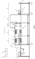
- Figure 1 shows a schematic longitudinal sectional view through a conveyor dishwasher 1 as an example of the solution according to the invention.
- the exemplary embodiment of the conveyor dishwasher 1 shown in figure 1 has a pre-wash zone 11 and a main-wash zone 12 which is arranged downstream of the pre-wash zone 11 as seen in the transportation direction T of the washware.
- a post-wash zone or pre-rinse zone 13 and a final rinse zone 14 are arranged downstream of the main-wash zone 12 in the case of the conveyor dishwasher 1 illustrated in figure 1 .
- the washware which is retained by washware carriers, in particular dish racks, in the case of the exemplary embodiment schematically illustrated in the drawings runs through an inlet tunnel 10, the following pre-wash zone 11, the main-wash zone 12, the post-wash or pre-rinse zone 13, the final rinse zone 14 and through a drying zone 15, into an outlet section 17.
- the abovementioned treatment zones 11, 12, 13 and 14 of the conveyor dishwasher 1 each have associated spray nozzles by means of which liquid is sprayed onto the washware which is transported through the respective treatment zones 11, 12, 13, 14 by the conveyor belt.
- the spray nozzles for example of the wash system which is associated with the pre-wash zone 11 and the main-wash zone 12, are in each case formed in an upper and lower wash tube, and therefore corresponding wash arms are used in these treatment zones 11, 12. It is feasible here for the wash systems which are used to have a large number of wash tubes which form a set of wash arms, wherein the large number of wash tubes is connected to a corresponding wash pump by means of a preferably common line system.
- each wash zone pre-wash zone 11, main-wash zone 12, post-wash zone 13
- tank wash tank
- sprayed liquid is accommodated, and/or in which liquid is provided for the spray nozzles of the relevant zones 11, 12, 13.
- wash zone used in this document is intended to be understood to mean, in principle, a treatment zone which has an associated recirculation tank (wash tank) and in which the liquid which is collected in the recirculation tank of the treatment zone is recirculated with the aid of a wash pump associated with the treatment zone.
- the term “wash zone” therefore covers the wash zone 11, the main-wash zone 12, but also a post-wash zone 13 which may be arranged downstream of the main-wash zone 12 as seen in the conveying direction T of the washware.
- the post-wash zone 13 is sometimes also referred to as a "pump final rinse zone” or "pre-rinse zone” in the field of commercial dishwashing. This is a recirculation final rinsing which precedes final rinsing with fresh water.
- final rinse zone used in this document is intended to be understood to mean a zone in which final rinsing with fresh water takes place, in which final rinsing the washware is sprayed with fresh water, to which final rinse aid may have been added, in order to free the washware of particles of dirt and detergent solution without residues.
- the last rinsing cycle prior to drying in the drying zone 15 therefore takes place in the final rinse zone 14.
- the drying zone 15 has an associated corresponding fan (not illustrated in the drawings) in order to provide a flow of warm air around the already cleaned washware and as a result to dry said washware.
- control device 50 which is only schematically illustrated in the drawings is provided, said control device serving (inter alia), in the case of the embodiment of the invention illustrated in the drawings, to actuate the respective wash pumps of the wash zones 11, 12, 13 during a washing process in a suitable manner in order to at least occasionally supply wash liquid to the corresponding spray nozzles by means of the associated line system.
- final rinse liquid in the form of fresh water, to which further chemical additives, such as final rinse aid for example, may have been added is sprayed onto the washware (not illustrated in figure 1 ) by means of the spray nozzles 2, which are arranged above and below a conveyor belt, of the final rinse zone 14.
- spray nozzles 2 which are arranged above and below a conveyor belt, of the final rinse zone 14.
- laterally arranged spray nozzles can also be provided in the final rinse zone 14.
- Some of the final rinse liquid which is sprayed in the final rinse zone 14 is transported from zone to zone, counter to the conveying direction T of the washware, by means of a cascade system. The rest is routed directly into the pre-wash tank of the pre-wash zone 11 by means of a valve and a bypass line (not illustrated).
- the final rinse liquid which is sprayed in the final rinse zone 14 is collected in the tank (post-wash or pre-rinse tank) of the post-wash or pre-rinse zone 13, from which it is conveyed by means of the wash pump belonging to the wash system of the post-wash or pre-rinse zone 13 to the spray nozzles 3 (post-wash or pre-rinse nozzles) of the post-wash or pre-rinse zone 13. Wash liquid is rinsed off the washware in the post-wash or pre-rinse zone 13.
- the wash liquid subsequently flows into the pre-wash tank of the pre-wash zone 11.
- the wash liquid which is collected in the pre-wash tank is sprayed onto the washware with the aid of a wash pump which belongs to the wash system of the pre-wash zone by means of spray nozzles (pre-wash nozzles 5) of the wash system which belongs to the pre-wash zone 11, in order to remove coarse dirt from the washware.
- the pre-wash zone 11 can be equipped with a tank covering sieve in the form of a planar sieve.
- This tank covering sieve is preferably arranged above the wash tank (pre-wash tank) of the pre-wash zone 11 in order to separate particles of dirt from the wash liquid which is sprayed in the pre-wash zone 11 and flows back into the pre-wash tank due to gravity.
- the mesh width of the tank covering sieve preferably lies in a range of between approximately 1 mm and 4 mm.
- Clouds of steam are produced owing to the heated wash and final rinse liquid when the latter are sprayed within the wash and final rinse zones 11, 12, 13, 14 of the conveyor dishwasher 1.
- clouds of steam it is advantageous, in the embodiment schematically illustrated in figure 1 , when the individual treatment zones and in particular the wash and final rinse zones 11, 12, 13, 14 are separated off by curtains 6.
- a detection system 30 is used, said detection system having a rack entry switch/rack entry sensor 31 which is arranged in a predefined region A at the inlet 10 or feed 16 of the conveyor dishwasher 1 and is designed in order to detect the presence of washware or a washware carrier 7 there.
- This rack entry switch/rack entry sensor 31 may be, for example, an optical, capacitive or inductive system, a light scanner or reed sensor, or a mechanical switch.
- another kind of sensor system or the like can also be used.
- the conveyor dishwasher 1 schematically illustrated in the drawings is a rack conveyor dishwasher in which the washware (not explicitly illustrated) - placed in dish carriers 7 or dish racks - is pushed from a feed 16 (feed table) into the inlet 10 (inlet channel) and, respectively, into the conveyor dishwasher 1 and there conveyed through the individual treatment zones 11, 12, 13, 14, 15 with the aid of the conveyor apparatus 20.
- the invention is not restricted to rack conveyor dishwashers of this kind, but rather can also be used, in general, with other types of machine, in particular flight-type dishwashers.
- the rack entry switch/rack entry sensor 31 which is provided in the region A at the inlet 10 or feed 16 of the conveyor dishwasher 1 is initiated when a washware carrier 7 (dish rack) which may be holding washware is placed into the inlet 10 or feed 16 of the conveyor dishwasher 1.
- the detection system 30 is connected to a control device 50, which is only schematically illustrated in the drawings, in such a way that the control device 50 actuates the conveyor apparatus 20 of the conveyor dishwasher 1 depending on whether washware or a washware carrier 7 is present in the region A at the inlet 10 or feed 16 of the conveyor dishwasher 1.
- the conveyor apparatus 20 is activated with the aid of the control device 50 when washware or a washware carrier 7 is detected in the region A at the inlet 10 or feed 16 of the conveyor dishwasher 1 with the aid of the rack entry switch/rack entry sensor 31.
- the conveyor apparatus 20 of the conveyor dishwasher 1 is activated with the aid of the control device 50 when the rack entry switch/rack entry sensor 31 which is provided at the inlet 10 or feed 16 of the conveyor dishwasher 1 is initiated or triggered by a washware carrier 7 (dish rack).
- the rack entry switch/rack entry sensor 31 of the detection system 30, which rack entry switch/rack entry sensor is provided at the inlet 10 or feed 16 of the conveyor dishwasher 1, is designed to output a corresponding signal to the detection system 30 or the control device 50 when it is detected that there is no (longer) washware or a washware carrier 7 in the region A at the inlet 10 or feed 16 of the conveyor dishwasher 1.
- the control device 50 then actuates the conveyor apparatus 20 in such a way that the conveyor apparatus 20 is deactivated.
- the detection system 30 further has a buffer switch/buffer sensor 32 which is provided in a predefined region B at the outlet 17 of the conveyor dishwasher 1.
- This buffer switch/buffer sensor 32 can - like the rack entry switch/rack entry sensor 31 which is provided at the inlet 10 or feed 16 of the conveyor dishwasher 1 - be designed as an optical, capacitive or inductive system.
- mechanically operated switches, reed switches or other types of switches, for example can also be used.
- the buffer switch/buffer sensor 32 which is provided in the predefined region B at the outlet 17 of the conveyor dishwasher 1 serves to detect whether washware or a washware carrier 7 is present in this region B. If this is the case, the buffer switch/buffer sensor 32 outputs a corresponding signal to the detection system 30, as a result of which the control device 50 actuates the conveyor apparatus 20 in a corresponding manner.
- At least one further switch/sensor which is likewise associated with the detection system 30 and is designed, in particular, as an end switch/end sensor 33 is used in the exemplary embodiment of the conveyor dishwasher 1 according to the invention illustrated in the drawings. As indicated in the drawings, this end switch/end sensor 33 is arranged in a predefined region within the end region C of the outlet 17 of the conveyor dishwasher 1 in order to detect the presence of washware or a washware carrier 7 there.
- the end switch/end sensor 33 is preferably an optically, capacitively or inductively operating system, or else a switch, in particular a mechanically operated switch, which is triggered when washware or a washware carrier 7 is pushed into the outlet 17 of the conveyor dishwasher 1 until the washware or the washware carrier 7 reaches the active region of the end switch/end sensor 33.
- the outlet 17 of the conveyor dishwasher 1 is dimensioned in such a way that it can receive at least two washware carriers 7 one behind the other as seen in the conveying direction T of the conveyor apparatus 20.
- Usual dimensions of the outlet 17 of a conveyor dishwasher 1 lie between 700 mm and 2000 mm.
- the feed 16 of the conveyor dishwasher 1, pre-clearing possibly also being performed in the region of said feed and said feed generally serving for loading washware carriers 7 (for example washware racks) with washware, is usually dimensioned in a similar manner to the outlet 17 and can receive at least two standard washware carriers 7.
- the schematic illustrations in the drawings further show that the rack entry switch/rack entry sensor 31 of the detection system 30 is preferably arranged in a region A at the inlet 10 of the conveyor dishwasher 1, the conveyor apparatus 20 already being active in said region.
- This is intended to be understood to mean, in particular, that, in a case when washware or a washware carrier 7 is situated in the active region of the rack entry switch/rack entry sensor 31, this washware or this washware carrier 7 is conveyed in conveying direction T when the conveyor apparatus 20 is active.
- the buffer switch/buffer sensor 32 of the detection system 30 is arranged in a region B at the outlet 17 of the conveyor dishwasher 1, and preferably - as indicated in the drawings - in a region of the outlet 17 of the conveyor dishwasher 1 which is no longer in the active region of the conveyor apparatus 20 of the conveyor dishwasher 1.
- This buffer switch/buffer sensor 32 is usually arranged 0 to 500 mm, and preferably 100 to 300 mm, downstream of the beginning of the outlet.
- the end switch/end sensor 33 which also belongs to the detection system 30 is arranged in the end region C, and preferably immediately at the end of the outlet 17.
- the conveyor dishwasher is operated in at least two operating modes.
- the first operating mode which is also called the "first operating state" in this document, in this case represents a standard situation in which the washware carrier 7 is transported through the individual treatment zones 11, 12, 13, 14, 15 of the conveyor dishwasher 1 without the conveyor apparatus 20 stopping.
- the buffer switch/buffer sensor 32 is initiated at the outlet 17 of the conveyor dishwasher 1, that is to say when, for example, a washware carrier 7 operates the buffer switch/buffer sensor 32 at the interface between the conveyor dishwasher 1 and the outlet 17 which is designed, for example, as an outlet table
- the conveyor apparatus 20 of the conveyor dishwasher 1 is deactivated by means of the control device 50, and therefore transportation of the washware carriers 7 through the treatment zones 11, 12, 13, 14, 15 of the conveyor dishwasher 1 is interrupted.
- the conveyor dishwasher 1 is switched over to the second operating mode ("buffer operation") by the buffer switch/buffer sensor 32 being triggered/operated.
- the conveyor apparatus 20 is activated by means of the control device 50 only when the rack entry switch/rack entry sensor 31 at the inlet 10 or feed 16 of the conveyor dishwasher 1 is covered by a washware carrier 7 or washware.
- the conveyor apparatus 20 is activated in the second operating mode (buffer operation) only when new washware, such as a new washware carrier 7 for example, is introduced into the dishwasher.
- new washware such as a new washware carrier 7 for example
- the conveyor apparatus 20 In the second operating mode (buffer operation), the conveyor apparatus 20 is - as already discussed - only activated when the rack entry switch/rack entry sensor 31 is covered. As soon as the washware or the washware carrier 7 has been transported out of the active region of the rack entry switch/rack entry sensor 31, the conveyor apparatus 20 is deactivated.
- the above-described second operating mode (buffer operation) is deactivated again by the washware or the washware carriers 7 being unloaded at the outlet 17 of the conveyor dishwasher 1. This can be performed, for example, by the end switch/end sensor 33 being triggered or by the buffer switch/buffer sensor 32 being cleared.
- the conveyor apparatus 20 is then activated again without interruption with the aid of the control device 50, specifically at least until all of the washware or all of the washware carriers 7 have been conveyed through the treatment zones 11, 12, 13, 14, 15 of the conveyor dishwasher 1.
- Renewed buffer operation (that is to say a changeover to the second operating mode) is preferably made possible again only when washware or a washware carrier 7 is pushed into an empty dishwasher and said washware or washware carrier then reaches the buffer switch/buffer sensor 32.
- the unloading behavior of the conveyor dishwasher 1 can be monitored by the detection system 30 or the buffer switch/buffer sensor 32 of the detection system 30. Additional information relating to the loading behavior is available in combination with the rack entry switch/rack entry sensor 31. Intelligent control of the conveyor apparatus 20 is made possible by combining the two items of information.
- control device 50 is designed to activate the conveyor apparatus 20 with a time delay when washware or a washware carrier 7 is detected in the region at the inlet 10 or feed 16 of the conveyor dishwasher 1.
- the conveyor dishwasher 1 it is possible for the conveyor dishwasher 1 to be designed to also deactivate the corresponding wash and final rinse systems (switch off the corresponding wash and final rinse pumps) in a state in which the conveyor apparatus 20 is deactivated, that is to say when no washware is transported through the individual treatment zones 11, 12, 13, 14, 15 of the conveyor dishwasher 1, in order to thereby save resources (energy, fresh water, chemicals) in the deactivated state of the conveyor apparatus 20.
- Delayed activation of the conveyor apparatus 20 has the result that a certain "lead time" is cleared for the wash and final rinse systems of the conveyor dishwasher 1 in order to be able to build up the nozzle pressure which is required for effective treatment of the washware.
- the time delay in activating the conveyor apparatus 20 is preferably manually adjustable and lies in a range of between 0 and 10 s.
- control device 50 is designed to deactivate the conveyor apparatus 20 only when no washware is detected in the region at the inlet 10 or feed 16 of the conveyor dishwasher 1 for a certain time.
- This time is also preferably manually adjustable and amounts to between 0 and 10 s.
- the invention relates not only to a conveyor dishwasher 1 but also to a corresponding method for operating a conveyor dishwasher 1. This method is distinguished, in particular, by the following method steps:
- the method further comprises the following method steps:
- the method preferably further comprises the following method steps:
Landscapes
- Washing And Drying Of Tableware (AREA)
Claims (8)
- Transportspülmaschine (1), insbesondere in Form einer Bandtransportspülmaschine oder Korbtransportspülmaschine mit einer Fördervorrichtung (20) zum Befördern von Spülgut durch die einzelnen Behandlungszonen (11, 12, 13, 14, 15) der Transportspülmaschine (1),wobei die Transportspülmaschine (1) einErfassungssystem (30) aufweist, das so ausgebildet ist, dass es das Vorhandensein von Spülgut oder einemSpülgutträger (7) in einem vordefinierten Bereich (A) an einem Einlass (10) oder einem Zulauf (16) der Transportspülmaschine (1) erfasst; und wobei eine Steuervorrichtung (50) vorgesehen ist, wobei die Steuervorrichtung so ausgebildet ist, dass sie die Fördervorrichtung (20) derart betätigt, dass:- die Fördervorrichtung (20) aktiviert wird, wenn Spülgut oder ein Spülgutträger (7) in dem Bereich (A) an dem Einlass (10) oder dem Zulauf (16) der Transportspülmaschine (1) erfasst wird; und- die Fördervorrichtung (20) deaktiviert wird, wenn kein Spülgut oder kein Spülgutträger (7) in dem Bereich (A) an dem Einlass (10) oder dem Zulauf (16) der Transportspülmaschine (1) erfasst wird,wobei der Auslauf (17) der Transportspülmaschine (1) vorzugsweise - in einer Förderrichtung (T) des Spülguts gesehen - der Fördervorrichtung (20) unmittelbar nachgeschaltet angeordnet ist, und wobei das Erfassungssystem (30) so ausgebildet ist, dass es das Vorhandensein von Spülgut oder einem Spülgutträger (7) in dem vordefinierten Bereich (B) des Auslaufs (17) der Transportspülmaschine (1) erfasst, und wobei die Steuervorrichtung (50) ferner so ausgebildet ist, dass sie die Fördervorrichtung (20) abhängig davon betätigt, ob Spülgut oder ein Spülgutträger (7) in dem Bereich (B) des Auslaufs (17) der Transportspülmaschine (1) vorhanden ist, wobei das Erfassungssystem (30) ferner so ausgebildet ist, dass es das Vorhandensein von Spülgut oder einem Spülgutträger (7) in einem vordefinierten Bereich (B) eines Auslaufs (17) der Transportspülmaschine (1) erfasst, und wobei die Steuervorrichtung (50) ferner so ausgebildet ist, dass sie die Fördervorrichtung (20) abhängig davon betätigt, ob Spülgut oder ein Spülgutträger (7) in dem Bereich (B) an dem Auslauf (17) der Transportspülmaschine (1) vorhanden ist,dadurch gekennzeichnet, dassdie Steuervorrichtung (50) so ausgebildet ist, dass sie in einem ersten Betriebszustand der Transportspülmaschine (1) die Fördervorrichtung (20) unabhängig davon aktiviert, ob Spülgut oder ein Spülgutträger (7) in dem Bereich (A) an dem Einlass (10) oder in dem Zulauf (16) der Transportspülmaschine (1) vorhanden ist, und in einem zweiten Betriebszustand der Transportspülmaschine (1) die Fördervorrichtung (20) derart betätigt, dass:- die Fördervorrichtung (20) aktiviert wird, wenn Spülgut oder ein Spülgutträger (7) jeweils in dem Bereich (A) an dem Einlass (10) oder dem Zulauf (16) der Transportspülmaschine (1) und in dem Bereich (B) an dem oder in dem Auslauf (17) der Transportspülmaschine (1) erfasst wird; und- die Fördervorrichtung (20) deaktiviert wird, wenn in dem Bereich (A) an dem Einlass (10) oder dem Zulauf (16) der Transportspülmaschine (1) kein Spülgut oder kein Spülgutträger (7) und in dem Bereich (B) an dem oder in dem Auslauf (17) der Transportspülmaschine (1) ein Spülgut oder ein Spülgutträger (7) erfasst wird.
- Transportspülmaschine (1) nach Anspruch 1,
wobei der Auslauf (17) der Transportspülmaschine (1) zur Aufnahme einer großen Anzahl von Spülgütern und/oder Spülgutträgern (7) ausgebildet ist, wobei der Bereich (B) des Auslaufs (17), in dem das Vorhandensein von Spülgut oder eines Spülgutträgers (7) mithilfe des Erfassungssystems (30) erfasst werden kann, in Förderrichtung (T) des Spülguts gesehen einem Endbereich (C) des Auslaufs (17) vorgeschaltet angeordnet ist. - Transportspülmaschine (1) nach Anspruch 1 oder 2,
wobei der Bereich (B) des Auslaufs (17), in dem das Vorhandensein von Spülgut oder eines Spülgutträgers (7) mithilfe des Erfassungssystems (30) erfasst werden kann, 0 bis 500 mm, vorzugsweise 100 bis 300 mm, in Förderrichtung (T) des Spülgutes gesehen, dem Beginn des Auslaufs (17) nachgeschaltet angeordnet ist. - Transportspülmaschine (1) nach einem der Ansprüche 1 bis 3,
wobei der Bereich (A) an dem Einlass (10) oder dem Zulauf (16) der Transportspülmaschine (1), in dem das Vorhandensein von Spülgut oder einem Spülgutträger (7) mithilfe des Erfassungssystems (30) erfasst werden kann, in Förderrichtung (T) des Spülguts gesehen im Einlassbereich einer ersten Behandlungszone (11) der Transportspülmaschine (1) und insbesondere in einem Einlasstunnel der Transportspülmaschine (1) angeordnet ist. - Transportspülmaschine (1) nach einem der Ansprüche 1 bis 4, wobei das Erfassungssystem (30) zumindest einen optischen, kapazitiven oder induktiven Sensor und/oder Schalter (31, 32, 33), insbesondere Kontaktschalter, aufweist.
- Transportspülmaschine (1) nach einem der Ansprüche 1 bis 5, wobei die Steuervorrichtung (50) so ausgebildet ist, dass sie die Fördervorrichtung (20) abhängig von einem Beladungszustand der Transportspülmaschine (1) mit einer Zeitverzögerung aktiviert oder deaktiviert, wobei der Beladungszustand mithilfe des Erfassungssystems (30) erfasst wird, wobei die Steuervorrichtung (50) vorzugsweise so ausgebildet ist, dass sie die Fördervorrichtung (20) mit einer Zeitverzögerung aktiviert, wenn Spülgut oder ein Spülgutträger (7) in dem Bereich (A) an dem Einlass (10) oder dem Zulauf (16) der Transportspülmaschine (1) erfasst wird, und/oder die Fördervorrichtung (20) deaktiviert, wenn eine bestimmte Zeit lang, bevorzugt 0 bis 10 s, kein Spülgut oder kein Spülgutträger (7) in dem Bereich (A) an dem Einlass (10) oder dem Zulauf (16) der Transportspülmaschine (1) erfasst wird.
- Verfahren zum Betreiben einer Transportspülmaschine (1) nach einem der Ansprüche 1 bis 6,wobei das Verfahren die folgenden Verfahrensschritte aufweist:i) ein Erfassungssystem (30) wird verwendet, um zu erfassen, ob Spülgut oder ein Spülgutträger (7) in einem Bereich (A) an einem Einlass (10) oder einem Zulauf (16) der Transportspülmaschine (1) vorhanden ist; undii)eine Steuervorrichtung (50) wird zum Aktivieren einer Fördervorrichtung (20) der Transportspülmaschine (1) verwendet, wenn Spülgut oder ein Spülgutträger (7) in dem Bereich (A) an dem Einlass (10) oder dem Zulauf (16) der Transportspülmaschine (1) erfasst wird, und zum Deaktivieren der Fördervorrichtung, wenn kein Spülgut oder kein Spülgutträger (7) in dem Bereich (A) an dem Einlass (10) oder dem Zulauf (16) der Transportspülmaschine (1) erfasst wird,wobei das Verfahren ferner die folgenden Verfahrensschritte aufweist:- das Erfassungssystem (30) wird verwendet, um zu erfassen, ob Spülgut oder ein Spülgutträger (7) in einem Bereich (B) an einem Auslauf (17) der Transportspülmaschine (1) vorhanden ist; und- die Steuereinrichtung (50) wird verwendet, um die Fördervorrichtung (20) zu aktivieren, wenn in dem Bereich (A) an dem Einlass (10) oder dem Zulauf (16) der Transportspülmaschine (1) und in dem Bereich (B) an dem oder in dem Auslauf (17) der Transportspülmaschine (1) jeweils Spülgut oder ein Spülgutträger (7) erfasst wird, und die Fördervorrichtung zu deaktivieren, wenn in dem Bereich (A) an dem Einlass (10) oder dem Zulauf (16) der Transportspülmaschine (1) kein Spülgut oder kein Spülgutträger (7) und in dem Bereich (B) an dem oder in dem Auslauf (17) der Transportspülmaschine (1) ein Spülgutträger (7) erfasst wird.
- Verfahren nach Anspruch 7,
wobei das Verfahren ferner die folgenden Verfahrensschritte aufweist:- das Erfassungssystem (30) wird verwendet, um zu erfassen, ob Spülgut oder ein Spülgutträger (7) in einem Endbereich (C) des Auslaufs (17) der Geschirrspülmaschine vorhanden ist; und- die Steuereinrichtung (50) wird verwendet, um die Fördervorrichtung (20) zu aktivieren, wenn in dem Bereich (A) an dem Einlass (10) oder dem Zulauf (16) der Transportspülmaschine (1) und in dem Bereich (B) an dem oder in dem Auslauf (17) der Transportspülmaschine (1) und wenn zusätzlich kein Spülgut oder kein Spülgutträger (7) in dem Endbereich (C) des Auslaufs (17) der Transportspülmaschine (1) jeweils Spülgut oder ein Spülgutträger (7) erfasst wird, und die Fördervorrichtung zu deaktivieren, wenn in dem Bereich (A) an dem Einlass (10) oder dem Zulauf (16) der Transportspülmaschine (1) kein Spülgut oder kein Spülgutträger (7) und in dem Bereich (B) an dem oder in dem Auslauf (17) der Transportspülmaschine (1) ein Spülgutträger (7) erfasst wird.
Applications Claiming Priority (2)
| Application Number | Priority Date | Filing Date | Title |
|---|---|---|---|
| DE102015214300.7A DE102015214300B4 (de) | 2015-07-28 | 2015-07-28 | Transportspülmaschine sowie Verfahren zum Betreiben einer Transportspülmaschine |
| PCT/US2016/043473 WO2017019477A1 (en) | 2015-07-28 | 2016-07-22 | Conveyor dishwasher and method for operating a conveyor dishwasher |
Publications (2)
| Publication Number | Publication Date |
|---|---|
| EP3328261A1 EP3328261A1 (de) | 2018-06-06 |
| EP3328261B1 true EP3328261B1 (de) | 2024-05-22 |
Family
ID=56555854
Family Applications (1)
| Application Number | Title | Priority Date | Filing Date |
|---|---|---|---|
| EP16745368.7A Active EP3328261B1 (de) | 2015-07-28 | 2016-07-22 | Förderbandartiger geschirrspüler und verfahren für den betrieb eines förderbandartigen geschirrspülers |
Country Status (6)
| Country | Link |
|---|---|
| US (1) | US10835098B2 (de) |
| EP (1) | EP3328261B1 (de) |
| CN (1) | CN108135432B (de) |
| AU (1) | AU2016297774B2 (de) |
| DE (1) | DE102015214300B4 (de) |
| WO (1) | WO2017019477A1 (de) |
Families Citing this family (10)
| Publication number | Priority date | Publication date | Assignee | Title |
|---|---|---|---|---|
| DE102017121978A1 (de) * | 2017-09-22 | 2017-11-30 | Illinois Tool Works Inc. | Spülmaschine |
| JP7356301B2 (ja) * | 2019-09-09 | 2023-10-04 | ホシザキ株式会社 | 洗浄システム |
| DE102020104654A1 (de) * | 2020-02-21 | 2021-08-26 | Illinois Tool Works Inc. | System zum beladen einer transportspülmaschine |
| US11375874B2 (en) | 2020-03-30 | 2022-07-05 | Whirlpool Corporation | Dishwasher with a dish rack and utensil caddy |
| DE102020114364A1 (de) * | 2020-05-28 | 2021-12-02 | Illinois Tool Works Inc. | System zum beladen mindestens einer transportspülmaschine mit spülgutteilen, anordnung aus mindestens einer transportspülmaschine und einem beladesystem sowie verfahren zum beladen mindestens einer transportspülmaschine mit spülgutteilen |
| CN111820837B (zh) * | 2020-07-17 | 2021-07-27 | 上海秒针网络科技有限公司 | 一种碗筐收纳装置及清洗系统 |
| JP6853465B1 (ja) * | 2020-08-18 | 2021-03-31 | 株式会社フィールド | 食器回収システム及びそれを備えた食器洗浄機 |
| JP7821594B2 (ja) * | 2021-11-24 | 2026-02-27 | ホシザキ株式会社 | 洗浄システム |
| IT202200019914A1 (it) * | 2022-09-28 | 2024-03-28 | Imf Eng S R L | Trasportatore senza fine a catene parellele |
| US20250387000A1 (en) * | 2024-06-19 | 2025-12-25 | Narasimha Mandapaka | Dish cleaning system |
Family Cites Families (14)
| Publication number | Priority date | Publication date | Assignee | Title |
|---|---|---|---|---|
| GB2087717A (en) | 1980-11-12 | 1982-06-03 | Chemed Corp | Dishwasher and method of controlling operation of same |
| SE8105811L (sv) | 1981-10-01 | 1983-04-02 | Electrolux Ab | Kontinuerlig diskmaskin |
| US4561904A (en) | 1984-09-21 | 1985-12-31 | Hobart Corporation | Control system and method of controlling a dishwashing machine |
| FI96661C (fi) | 1994-05-02 | 2000-11-20 | Fuuga Controls Oy | Menetelmä yksikköjen pesemiseksi automaattisessa pesulinjassa sekä automaattinen pesulaitteisto |
| JP2791862B2 (ja) * | 1994-08-22 | 1998-08-27 | 谷口工業株式会社 | 洗浄篭受け渡し装置 |
| FI990487L (fi) | 1999-03-05 | 2000-09-06 | Hackman Metos Oy | Menetelmä yksikköjen pesemiseksi automaattisessa pesulaitteistossa ja automaattinen pesulaitteisto |
| DE102008037344B4 (de) * | 2008-08-11 | 2019-01-31 | Premark Feg L.L.C. | Transportspülmaschine und Verfahren zum Betreiben einer Transportspülmaschine |
| DE102008037683B4 (de) * | 2008-08-14 | 2019-05-02 | Premark Feg L.L.C. | Transportspülmaschine sowie Verfahren zum Betreiben einer Transportspülmaschine |
| DE102009059784B4 (de) * | 2009-12-18 | 2016-05-12 | Meiko Maschinenbau Gmbh & Co. Kg | Reinigungsvorrichtung mit Betätigungselement |
| DE102011007507B4 (de) * | 2011-04-15 | 2016-06-02 | Premark Feg L.L.C. | Transportspülmaschine sowie Verfahren zum Betreiben einer Transportspülmaschine |
| WO2013057539A1 (zh) | 2011-10-18 | 2013-04-25 | Li Xiaoying | 一种解决行李、物料传输的新方法----一对一传输方法 |
| DE102013226080B4 (de) | 2013-12-16 | 2024-10-02 | Meiko Maschinenbau Gmbh & Co. Kg | Reinigungsvorrichtung und Verfahren zum Reinigen von Reinigungsgut |
| CN204137817U (zh) * | 2014-08-06 | 2015-02-04 | 天津福莱迪科技发展有限公司 | 一种智能传送带 |
| CN104386487A (zh) * | 2014-10-30 | 2015-03-04 | 昆山迈致治具科技有限公司 | 手表密封性测试治具 |
-
2015
- 2015-07-28 DE DE102015214300.7A patent/DE102015214300B4/de active Active
-
2016
- 2016-07-22 AU AU2016297774A patent/AU2016297774B2/en not_active Ceased
- 2016-07-22 US US15/747,901 patent/US10835098B2/en active Active
- 2016-07-22 WO PCT/US2016/043473 patent/WO2017019477A1/en not_active Ceased
- 2016-07-22 EP EP16745368.7A patent/EP3328261B1/de active Active
- 2016-07-22 CN CN201680040593.1A patent/CN108135432B/zh active Active
Also Published As
| Publication number | Publication date |
|---|---|
| AU2016297774A1 (en) | 2018-02-01 |
| CN108135432B (zh) | 2021-07-16 |
| AU2016297774B2 (en) | 2019-08-01 |
| US20180213999A1 (en) | 2018-08-02 |
| DE102015214300B4 (de) | 2026-02-05 |
| EP3328261A1 (de) | 2018-06-06 |
| DE102015214300A1 (de) | 2017-02-02 |
| US10835098B2 (en) | 2020-11-17 |
| WO2017019477A1 (en) | 2017-02-02 |
| CN108135432A (zh) | 2018-06-08 |
Similar Documents
| Publication | Publication Date | Title |
|---|---|---|
| EP3328261B1 (de) | Förderbandartiger geschirrspüler und verfahren für den betrieb eines förderbandartigen geschirrspülers | |
| US8746262B2 (en) | Conveyor dishwasher and method for operating a conveyor dishwasher | |
| CN104224079B (zh) | 传送式洗碗机及其使用方法 | |
| CA2717568C (en) | Conveyor warewasher and method for operating a conveyor warewasher | |
| EP2696738B1 (de) | Förderbandartiger geschirrspüler und verfahren für den betrieb eines förderbandartigen geschirrspülers | |
| EP2346619B1 (de) | System zum waschen von spülgut und verfahren zum betreiben eines derartigen systems | |
| EP3735887B1 (de) | Bandspülmaschine | |
| CA2537541C (en) | Conveyor-type dishwasher and method for it | |
| CN111107775A (zh) | 洗碗机 | |
| CN109068932B (zh) | 用于清洗待洗器皿的传送式洗碗机 | |
| US20240099550A1 (en) | Conveyor warewasher and method for operating a conveyor warewasher |
Legal Events
| Date | Code | Title | Description |
|---|---|---|---|
| STAA | Information on the status of an ep patent application or granted ep patent |
Free format text: STATUS: THE INTERNATIONAL PUBLICATION HAS BEEN MADE |
|
| PUAI | Public reference made under article 153(3) epc to a published international application that has entered the european phase |
Free format text: ORIGINAL CODE: 0009012 |
|
| STAA | Information on the status of an ep patent application or granted ep patent |
Free format text: STATUS: REQUEST FOR EXAMINATION WAS MADE |
|
| 17P | Request for examination filed |
Effective date: 20180116 |
|
| AK | Designated contracting states |
Kind code of ref document: A1 Designated state(s): AL AT BE BG CH CY CZ DE DK EE ES FI FR GB GR HR HU IE IS IT LI LT LU LV MC MK MT NL NO PL PT RO RS SE SI SK SM TR |
|
| AX | Request for extension of the european patent |
Extension state: BA ME |
|
| RIN1 | Information on inventor provided before grant (corrected) |
Inventor name: HEIDT, MARKUS Inventor name: DISCH, HARALD Inventor name: KLUMPP, PHILIPP |
|
| DAV | Request for validation of the european patent (deleted) | ||
| DAX | Request for extension of the european patent (deleted) | ||
| STAA | Information on the status of an ep patent application or granted ep patent |
Free format text: STATUS: EXAMINATION IS IN PROGRESS |
|
| 17Q | First examination report despatched |
Effective date: 20200731 |
|
| GRAP | Despatch of communication of intention to grant a patent |
Free format text: ORIGINAL CODE: EPIDOSNIGR1 |
|
| STAA | Information on the status of an ep patent application or granted ep patent |
Free format text: STATUS: GRANT OF PATENT IS INTENDED |
|
| INTG | Intention to grant announced |
Effective date: 20240301 |
|
| GRAS | Grant fee paid |
Free format text: ORIGINAL CODE: EPIDOSNIGR3 |
|
| GRAA | (expected) grant |
Free format text: ORIGINAL CODE: 0009210 |
|
| STAA | Information on the status of an ep patent application or granted ep patent |
Free format text: STATUS: THE PATENT HAS BEEN GRANTED |
|
| AK | Designated contracting states |
Kind code of ref document: B1 Designated state(s): AL AT BE BG CH CY CZ DE DK EE ES FI FR GB GR HR HU IE IS IT LI LT LU LV MC MK MT NL NO PL PT RO RS SE SI SK SM TR |
|
| REG | Reference to a national code |
Ref country code: GB Ref legal event code: FG4D |
|
| REG | Reference to a national code |
Ref country code: CH Ref legal event code: EP |
|
| REG | Reference to a national code |
Ref country code: DE Ref legal event code: R096 Ref document number: 602016087622 Country of ref document: DE |
|
| REG | Reference to a national code |
Ref country code: IE Ref legal event code: FG4D |
|
| P01 | Opt-out of the competence of the unified patent court (upc) registered |
Free format text: CASE NUMBER: APP_41379/2024 Effective date: 20240712 |
|
| REG | Reference to a national code |
Ref country code: LT Ref legal event code: MG9D |
|
| REG | Reference to a national code |
Ref country code: NL Ref legal event code: MP Effective date: 20240522 |
|
| PG25 | Lapsed in a contracting state [announced via postgrant information from national office to epo] |
Ref country code: IS Free format text: LAPSE BECAUSE OF FAILURE TO SUBMIT A TRANSLATION OF THE DESCRIPTION OR TO PAY THE FEE WITHIN THE PRESCRIBED TIME-LIMIT Effective date: 20240922 |
|
| PG25 | Lapsed in a contracting state [announced via postgrant information from national office to epo] |
Ref country code: BG Free format text: LAPSE BECAUSE OF FAILURE TO SUBMIT A TRANSLATION OF THE DESCRIPTION OR TO PAY THE FEE WITHIN THE PRESCRIBED TIME-LIMIT Effective date: 20240522 |
|
| PG25 | Lapsed in a contracting state [announced via postgrant information from national office to epo] |
Ref country code: FI Free format text: LAPSE BECAUSE OF FAILURE TO SUBMIT A TRANSLATION OF THE DESCRIPTION OR TO PAY THE FEE WITHIN THE PRESCRIBED TIME-LIMIT Effective date: 20240522 Ref country code: HR Free format text: LAPSE BECAUSE OF FAILURE TO SUBMIT A TRANSLATION OF THE DESCRIPTION OR TO PAY THE FEE WITHIN THE PRESCRIBED TIME-LIMIT Effective date: 20240522 |
|
| PG25 | Lapsed in a contracting state [announced via postgrant information from national office to epo] |
Ref country code: GR Free format text: LAPSE BECAUSE OF FAILURE TO SUBMIT A TRANSLATION OF THE DESCRIPTION OR TO PAY THE FEE WITHIN THE PRESCRIBED TIME-LIMIT Effective date: 20240823 |
|
| PG25 | Lapsed in a contracting state [announced via postgrant information from national office to epo] |
Ref country code: PT Free format text: LAPSE BECAUSE OF FAILURE TO SUBMIT A TRANSLATION OF THE DESCRIPTION OR TO PAY THE FEE WITHIN THE PRESCRIBED TIME-LIMIT Effective date: 20240923 |
|
| REG | Reference to a national code |
Ref country code: AT Ref legal event code: MK05 Ref document number: 1688081 Country of ref document: AT Kind code of ref document: T Effective date: 20240522 |
|
| PG25 | Lapsed in a contracting state [announced via postgrant information from national office to epo] |
Ref country code: NL Free format text: LAPSE BECAUSE OF FAILURE TO SUBMIT A TRANSLATION OF THE DESCRIPTION OR TO PAY THE FEE WITHIN THE PRESCRIBED TIME-LIMIT Effective date: 20240522 |
|
| PG25 | Lapsed in a contracting state [announced via postgrant information from national office to epo] |
Ref country code: ES Free format text: LAPSE BECAUSE OF FAILURE TO SUBMIT A TRANSLATION OF THE DESCRIPTION OR TO PAY THE FEE WITHIN THE PRESCRIBED TIME-LIMIT Effective date: 20240522 |
|
| PG25 | Lapsed in a contracting state [announced via postgrant information from national office to epo] |
Ref country code: AT Free format text: LAPSE BECAUSE OF FAILURE TO SUBMIT A TRANSLATION OF THE DESCRIPTION OR TO PAY THE FEE WITHIN THE PRESCRIBED TIME-LIMIT Effective date: 20240522 |
|
| PG25 | Lapsed in a contracting state [announced via postgrant information from national office to epo] |
Ref country code: PL Free format text: LAPSE BECAUSE OF FAILURE TO SUBMIT A TRANSLATION OF THE DESCRIPTION OR TO PAY THE FEE WITHIN THE PRESCRIBED TIME-LIMIT Effective date: 20240522 |
|
| PG25 | Lapsed in a contracting state [announced via postgrant information from national office to epo] |
Ref country code: LV Free format text: LAPSE BECAUSE OF FAILURE TO SUBMIT A TRANSLATION OF THE DESCRIPTION OR TO PAY THE FEE WITHIN THE PRESCRIBED TIME-LIMIT Effective date: 20240522 |
|
| PG25 | Lapsed in a contracting state [announced via postgrant information from national office to epo] |
Ref country code: PT Free format text: LAPSE BECAUSE OF FAILURE TO SUBMIT A TRANSLATION OF THE DESCRIPTION OR TO PAY THE FEE WITHIN THE PRESCRIBED TIME-LIMIT Effective date: 20240923 Ref country code: PL Free format text: LAPSE BECAUSE OF FAILURE TO SUBMIT A TRANSLATION OF THE DESCRIPTION OR TO PAY THE FEE WITHIN THE PRESCRIBED TIME-LIMIT Effective date: 20240522 Ref country code: NO Free format text: LAPSE BECAUSE OF FAILURE TO SUBMIT A TRANSLATION OF THE DESCRIPTION OR TO PAY THE FEE WITHIN THE PRESCRIBED TIME-LIMIT Effective date: 20240822 Ref country code: NL Free format text: LAPSE BECAUSE OF FAILURE TO SUBMIT A TRANSLATION OF THE DESCRIPTION OR TO PAY THE FEE WITHIN THE PRESCRIBED TIME-LIMIT Effective date: 20240522 Ref country code: LV Free format text: LAPSE BECAUSE OF FAILURE TO SUBMIT A TRANSLATION OF THE DESCRIPTION OR TO PAY THE FEE WITHIN THE PRESCRIBED TIME-LIMIT Effective date: 20240522 Ref country code: IS Free format text: LAPSE BECAUSE OF FAILURE TO SUBMIT A TRANSLATION OF THE DESCRIPTION OR TO PAY THE FEE WITHIN THE PRESCRIBED TIME-LIMIT Effective date: 20240922 Ref country code: HR Free format text: LAPSE BECAUSE OF FAILURE TO SUBMIT A TRANSLATION OF THE DESCRIPTION OR TO PAY THE FEE WITHIN THE PRESCRIBED TIME-LIMIT Effective date: 20240522 Ref country code: GR Free format text: LAPSE BECAUSE OF FAILURE TO SUBMIT A TRANSLATION OF THE DESCRIPTION OR TO PAY THE FEE WITHIN THE PRESCRIBED TIME-LIMIT Effective date: 20240823 Ref country code: FI Free format text: LAPSE BECAUSE OF FAILURE TO SUBMIT A TRANSLATION OF THE DESCRIPTION OR TO PAY THE FEE WITHIN THE PRESCRIBED TIME-LIMIT Effective date: 20240522 Ref country code: ES Free format text: LAPSE BECAUSE OF FAILURE TO SUBMIT A TRANSLATION OF THE DESCRIPTION OR TO PAY THE FEE WITHIN THE PRESCRIBED TIME-LIMIT Effective date: 20240522 Ref country code: BG Free format text: LAPSE BECAUSE OF FAILURE TO SUBMIT A TRANSLATION OF THE DESCRIPTION OR TO PAY THE FEE WITHIN THE PRESCRIBED TIME-LIMIT Effective date: 20240522 Ref country code: AT Free format text: LAPSE BECAUSE OF FAILURE TO SUBMIT A TRANSLATION OF THE DESCRIPTION OR TO PAY THE FEE WITHIN THE PRESCRIBED TIME-LIMIT Effective date: 20240522 Ref country code: RS Free format text: LAPSE BECAUSE OF FAILURE TO SUBMIT A TRANSLATION OF THE DESCRIPTION OR TO PAY THE FEE WITHIN THE PRESCRIBED TIME-LIMIT Effective date: 20240822 |
|
| PG25 | Lapsed in a contracting state [announced via postgrant information from national office to epo] |
Ref country code: DK Free format text: LAPSE BECAUSE OF FAILURE TO SUBMIT A TRANSLATION OF THE DESCRIPTION OR TO PAY THE FEE WITHIN THE PRESCRIBED TIME-LIMIT Effective date: 20240522 |
|
| PG25 | Lapsed in a contracting state [announced via postgrant information from national office to epo] |
Ref country code: EE Free format text: LAPSE BECAUSE OF FAILURE TO SUBMIT A TRANSLATION OF THE DESCRIPTION OR TO PAY THE FEE WITHIN THE PRESCRIBED TIME-LIMIT Effective date: 20240522 |
|
| PG25 | Lapsed in a contracting state [announced via postgrant information from national office to epo] |
Ref country code: CZ Free format text: LAPSE BECAUSE OF FAILURE TO SUBMIT A TRANSLATION OF THE DESCRIPTION OR TO PAY THE FEE WITHIN THE PRESCRIBED TIME-LIMIT Effective date: 20240522 |
|
| PG25 | Lapsed in a contracting state [announced via postgrant information from national office to epo] |
Ref country code: RO Free format text: LAPSE BECAUSE OF FAILURE TO SUBMIT A TRANSLATION OF THE DESCRIPTION OR TO PAY THE FEE WITHIN THE PRESCRIBED TIME-LIMIT Effective date: 20240522 Ref country code: SK Free format text: LAPSE BECAUSE OF FAILURE TO SUBMIT A TRANSLATION OF THE DESCRIPTION OR TO PAY THE FEE WITHIN THE PRESCRIBED TIME-LIMIT Effective date: 20240522 |
|
| PG25 | Lapsed in a contracting state [announced via postgrant information from national office to epo] |
Ref country code: SM Free format text: LAPSE BECAUSE OF FAILURE TO SUBMIT A TRANSLATION OF THE DESCRIPTION OR TO PAY THE FEE WITHIN THE PRESCRIBED TIME-LIMIT Effective date: 20240522 |
|
| PG25 | Lapsed in a contracting state [announced via postgrant information from national office to epo] |
Ref country code: SM Free format text: LAPSE BECAUSE OF FAILURE TO SUBMIT A TRANSLATION OF THE DESCRIPTION OR TO PAY THE FEE WITHIN THE PRESCRIBED TIME-LIMIT Effective date: 20240522 Ref country code: SK Free format text: LAPSE BECAUSE OF FAILURE TO SUBMIT A TRANSLATION OF THE DESCRIPTION OR TO PAY THE FEE WITHIN THE PRESCRIBED TIME-LIMIT Effective date: 20240522 Ref country code: RO Free format text: LAPSE BECAUSE OF FAILURE TO SUBMIT A TRANSLATION OF THE DESCRIPTION OR TO PAY THE FEE WITHIN THE PRESCRIBED TIME-LIMIT Effective date: 20240522 Ref country code: EE Free format text: LAPSE BECAUSE OF FAILURE TO SUBMIT A TRANSLATION OF THE DESCRIPTION OR TO PAY THE FEE WITHIN THE PRESCRIBED TIME-LIMIT Effective date: 20240522 Ref country code: DK Free format text: LAPSE BECAUSE OF FAILURE TO SUBMIT A TRANSLATION OF THE DESCRIPTION OR TO PAY THE FEE WITHIN THE PRESCRIBED TIME-LIMIT Effective date: 20240522 Ref country code: CZ Free format text: LAPSE BECAUSE OF FAILURE TO SUBMIT A TRANSLATION OF THE DESCRIPTION OR TO PAY THE FEE WITHIN THE PRESCRIBED TIME-LIMIT Effective date: 20240522 |
|
| PG25 | Lapsed in a contracting state [announced via postgrant information from national office to epo] |
Ref country code: MC Free format text: LAPSE BECAUSE OF FAILURE TO SUBMIT A TRANSLATION OF THE DESCRIPTION OR TO PAY THE FEE WITHIN THE PRESCRIBED TIME-LIMIT Effective date: 20240522 Ref country code: IT Free format text: LAPSE BECAUSE OF FAILURE TO SUBMIT A TRANSLATION OF THE DESCRIPTION OR TO PAY THE FEE WITHIN THE PRESCRIBED TIME-LIMIT Effective date: 20240522 |
|
| REG | Reference to a national code |
Ref country code: DE Ref legal event code: R097 Ref document number: 602016087622 Country of ref document: DE |
|
| REG | Reference to a national code |
Ref country code: CH Ref legal event code: PL |
|
| PG25 | Lapsed in a contracting state [announced via postgrant information from national office to epo] |
Ref country code: LU Free format text: LAPSE BECAUSE OF NON-PAYMENT OF DUE FEES Effective date: 20240722 |
|
| PLBE | No opposition filed within time limit |
Free format text: ORIGINAL CODE: 0009261 |
|
| STAA | Information on the status of an ep patent application or granted ep patent |
Free format text: STATUS: NO OPPOSITION FILED WITHIN TIME LIMIT |
|
| PG25 | Lapsed in a contracting state [announced via postgrant information from national office to epo] |
Ref country code: LU Free format text: LAPSE BECAUSE OF NON-PAYMENT OF DUE FEES Effective date: 20240722 |
|
| GBPC | Gb: european patent ceased through non-payment of renewal fee |
Effective date: 20240822 |
|
| PG25 | Lapsed in a contracting state [announced via postgrant information from national office to epo] |
Ref country code: CH Free format text: LAPSE BECAUSE OF NON-PAYMENT OF DUE FEES Effective date: 20240731 Ref country code: SI Free format text: LAPSE BECAUSE OF FAILURE TO SUBMIT A TRANSLATION OF THE DESCRIPTION OR TO PAY THE FEE WITHIN THE PRESCRIBED TIME-LIMIT Effective date: 20240522 Ref country code: BE Free format text: LAPSE BECAUSE OF NON-PAYMENT OF DUE FEES Effective date: 20240731 |
|
| 26N | No opposition filed |
Effective date: 20250225 |
|
| REG | Reference to a national code |
Ref country code: BE Ref legal event code: MM Effective date: 20240731 |
|
| PG25 | Lapsed in a contracting state [announced via postgrant information from national office to epo] |
Ref country code: GB Free format text: LAPSE BECAUSE OF NON-PAYMENT OF DUE FEES Effective date: 20240822 |
|
| PG25 | Lapsed in a contracting state [announced via postgrant information from national office to epo] |
Ref country code: IE Free format text: LAPSE BECAUSE OF NON-PAYMENT OF DUE FEES Effective date: 20240722 |
|
| PG25 | Lapsed in a contracting state [announced via postgrant information from national office to epo] |
Ref country code: SE Free format text: LAPSE BECAUSE OF FAILURE TO SUBMIT A TRANSLATION OF THE DESCRIPTION OR TO PAY THE FEE WITHIN THE PRESCRIBED TIME-LIMIT Effective date: 20240522 |
|
| PGFP | Annual fee paid to national office [announced via postgrant information from national office to epo] |
Ref country code: DE Payment date: 20250729 Year of fee payment: 10 |
|
| PGFP | Annual fee paid to national office [announced via postgrant information from national office to epo] |
Ref country code: FR Payment date: 20250725 Year of fee payment: 10 |
|
| PG25 | Lapsed in a contracting state [announced via postgrant information from national office to epo] |
Ref country code: CY Free format text: LAPSE BECAUSE OF FAILURE TO SUBMIT A TRANSLATION OF THE DESCRIPTION OR TO PAY THE FEE WITHIN THE PRESCRIBED TIME-LIMIT; INVALID AB INITIO Effective date: 20160722 |
|
| PG25 | Lapsed in a contracting state [announced via postgrant information from national office to epo] |
Ref country code: HU Free format text: LAPSE BECAUSE OF FAILURE TO SUBMIT A TRANSLATION OF THE DESCRIPTION OR TO PAY THE FEE WITHIN THE PRESCRIBED TIME-LIMIT; INVALID AB INITIO Effective date: 20160722 |