EP3328312B1 - Dispositif d'ancrage orthodontique - Google Patents
Dispositif d'ancrage orthodontique Download PDFInfo
- Publication number
- EP3328312B1 EP3328312B1 EP16831956.4A EP16831956A EP3328312B1 EP 3328312 B1 EP3328312 B1 EP 3328312B1 EP 16831956 A EP16831956 A EP 16831956A EP 3328312 B1 EP3328312 B1 EP 3328312B1
- Authority
- EP
- European Patent Office
- Prior art keywords
- orthodontic
- tube
- passage
- base
- anchor
- Prior art date
- Legal status (The legal status is an assumption and is not a legal conclusion. Google has not performed a legal analysis and makes no representation as to the accuracy of the status listed.)
- Active
Links
Images


Classifications
-
- A—HUMAN NECESSITIES
- A61—MEDICAL OR VETERINARY SCIENCE; HYGIENE
- A61C—DENTISTRY; APPARATUS OR METHODS FOR ORAL OR DENTAL HYGIENE
- A61C7/00—Orthodontics, i.e. obtaining or maintaining the desired position of teeth, e.g. by straightening, evening, regulating, separating, or by correcting malocclusions
- A61C7/12—Brackets; Arch wires; Combinations thereof; Accessories therefor
- A61C7/28—Securing arch wire to bracket
- A61C7/282—Buccal tubes
Definitions
- the present invention relates to orthodontic anchors and more particularly but not exclusively to orthodontic anchorages that extend between and attach to two adjacent teeth.
- Orthodontics usually involved the treatment of either all the teeth in the mouth or all the teeth in one arch. There has been an increasing trend in recent decades for the cosmetically motivated treatment of only the anterior teeth - especially those primarily visible in the smile which are often the maxillary teeth. As there are six anterior teeth involved in the smile, be they maxillary or mandibular, this anterior segment is often referred to as the "social six".
- the treatment of these anterior teeth with clear plastic removable shells or trays - such as the Invisalign brand, the Clear Smile brand and many other emerging clones of this technology is highlighting the size of the market in the alignment and treatment of the anterior teeth as distinct from the correction of all the orthodontic problems within the mouth including the posterior segments. Many people, especially adults, are primarily concerned with the appearance of their crooked front teeth. They are not as concerned about fixing cross bite, insufficient arch width, open or deep bites or irregularities of alignment in the posterior segments.
- anterior segments which may also include some of the pre-molars
- brackets and wires but with a limited objective of levelling and aligning the anterior teeth and making them look cosmetically acceptable in as short as time possible.
- This emerging industry is what some people call 'six-month orthodontics'. However there are traps for unskilled operators in treating what appears to be a superficially simple anterior levelling and aligning treatment.
- Orthodontists are generally highly skilled and highly trained specialists within dentistry, trained to a level substantially higher than most undergraduate training for a general dentist. However many dentists embark upon treatment of the anterior segments on the advice of training institutions and promoters of six-month orthodontics. They may not be thoroughly grounded in anchorage principles or be aware of how to prevent problems that arise in the movement of anchor units coming from or as a result of the treatment of the anterior segment.
- the anterior teeth When the anterior teeth are bracketed and have wires attached to those brackets via means of elastic or wire ligatures there is often a degree of friction between the wire and the bracket.
- levelling and aligning the anterior teeth have a strong tendency to move towards and angle towards the buccal, partly due to the friction between the wire and the bracket. This tendency happens more so when the teeth are severely crowded, because as the wire straightens it is driven forward as a result of the friction in the premolars segments.
- Some orthodontists will employ a device known as a transpalatal arch in an attempt to lock the buccal roots into the buccal cortical plate and reduce their ability to move anteriorly.
- a device known as a transpalatal arch in an attempt to lock the buccal roots into the buccal cortical plate and reduce their ability to move anteriorly.
- this is a reasonably involved device to make and many general dentists would prefer not to make it, or, will not have sufficient training to understand how this device works or how to use it.
- it is not a foolproof device. Slippage can still occur and valuable stripped tooth material can be wasted in this anchor slippage.
- Known devices also utilise two molar pads which can be adhered or bonded to the buccal enamel of the two molars, usually referred to as the first and second molars, in any one arch - typically on the buccal side for greater comfort to the tongue.
- These molar pads may be glued or bonded and form the base foundation for the metallic device that attaches onto them which then engages the arch wire.
- a slot instead of a tube so that the wire can be placed on top and into the slot rather than inserted into the tube.
- the tube has a loosely affixed lid on it which can be peeled off. This is called a convertible tube so that it can be converted to a slot if the operator prefers.
- Malaligned molars are generally not splinted or frozen in their malaligned condition - they would typically be aligned by the arch wire due to the fact that most of the time the molar brackets or tubes are placed in the conventional ideal position relative to the tooth.
- the arch wire then does the straightening as per the classic straight wire technique, in which the brackets are all positioned ideally and the wire performs the orthodontic movements just by being straight and without the operator having to make complicated bends in the wire to move the teeth into an ideal aligned straightened condition.
- the molars are not ideally aligned but the patient is not having any functional problem and does not wish them to be the cause of delay in treating the anterior cosmetic problem.
- dentists and orthodontists will be treating a patient for 18 months or more for conventional orthodontics. Accordingly there is plenty of time available for them to realign the posterior teeth.
- the pressure is on the dentist or the orthodontist to get the cosmetic result as fast as possible so that the braces, which are not particularly pleasant to look at, and can be very uncomfortable and cause substantial ulceration in some patients, can be removed.
- Speed is of the essence especially when wires and brackets are used.
- the patients typical chief complaint is the unsightly or unpleasant nature of their natural tooth anterior malalignment, placing brackets and wires only makes this cosmetic problem worse, and the sooner the brackets and wires can come off the happier the patient will generally be.
- the arch wire typically extends distantly from the last bracket which is typically on the first molar. As this arch wire extends towards the distal it can cause substantial irritation and ulceration to the cheek and can even impale the cheek mucosa and cause substantial difficulty and sometimes an emergency for the patient.
- appointments are made every month and the excess wire that is protruding from the distal of the last bracket is trimmed back using a distal end cutter.
- a further disadvantage of known orthodontic anchors is that the anchors consist of a pad that is fixed to the tooth, with the pad then providing a pair of projections between which there is a groove or slot.
- the orthodontic wire is placed in the groove.
- the groove must be correctly oriented, and the wire must fit intimately into the groove. This provides the dentist with little leeway in respect of misalignment of the grooves/pad. If the wire is a loose fit then the tooth can move forward before the wire engages the groove and resists its forward tipping.
- wires are small to start with and only fit the groove towards the end of the treatment - during which time the Anchorage value of this situation is very limited.
- the present invention is concerned with an orthodontic anchor as defined in claim 1.
- Preferred embodiments or the orthodontic anchor are defined in dependent claims 2 to 6.
- the present invention is concerned with an orthodontic anchor assembly as defined in claim 7.
- Preferred embodiments or the orthodontic anchor assembly are defined in dependent claims 8 to 11.
- an orthodontic anchor 10 In this particular illustration the anchor 10 is attached to a tooth 11, that may, for example, be a molar, with the anchor 10 attached to the tooth surface 12.
- the anchor 10 includes a base 13 which is in the form of a plate, having a surface 14 that is fixed to the surface 12 by being adhered or bonded to the surface 12.
- the surface 12 may be on the palate side or the buccal side of the tooth 11.
- a duct portion 15 Fixed to or formed integral with the base 13 is a duct portion 15, that projects from the base 13 so as to extend from the base 13 in a direction away from the surface 14.
- the base 13 and portion 15 are integrally formed from metal.
- the duct portion 15 provides a through passage 16, that is generally parallel to the surface 14.
- the passage 16 may be of any desired cross-section, such as circular, elliptical, square or even round. However most preferably the passage 16 is generally oval in transverse cross-section so as to be upwardly elongated. Accordingly, the passage 16 has transverse width 17 that is less than the transverse length 18. That is, the passage 16 is transversely elongated in the direction generally parallel to the base 14, and transverse of the longitudinal axis 40 of the anchor 10.
- a tube 19 Extending through the passage 16 is a tube 19 having a longitudinal passage 20.
- the tube 19 is of a smaller cross-section that the passage 16 so that there is spaced between the outer longitudinal surface of the tube 19, and the internal surface of the portion 15 surrounding the passage 16.
- the tube 19 is plastically deformable so that bends can be provided, with the bends being located in the passage 16.
- the passage 20 is to provide for an elongated orthodontic element, such as a wire 21.
- the orthodontic element passes longitudinally through the passage 20 and move relative to the passage 20.
- the element may also be a chain.
- the element 21 may be resilient deformable, and/or plastically deformable.
- the portion 15 is provided with an injection passage 22 to which an applicator 23 is applied to inject the settable material into the passage 16.
- the applicator 23 would have a tubular nozzle 24 that would have an end extremity that fits within the passage 22.
- the abovementioned settable substance would be a self-curing cement such as a composite resin.
- the element 21 would then pass from the anchor 10, to an adjacent anchor device (pad) 25 fixed to an adjacent tooth 26.
- the anchor 10 would include a hook 27 or other projection that would be provided to assist the dental professional in positioning the anchor 10, or may also aid in the attachment of other orthodontic devices to the anchor 10.
- the portion 15 is arcuate outwardly in configuration to inhibit irritation.
- an orthodontic anchor assembly 30 includes two anchors 10 (as described previously) with the tube 19 passing therebetween and fixed to both bases so that the assembly 30 is fixed to two adjacent teeth 31 and 32, more particularly the anchors 10 are fixed to surfaces 33 and 34 of the teeth 31 and 32.
- the tube 19 is fixed to both bases 11 by the abovementioned settable substance being located in the passages 16 and set to fix the tube 19 to both bases 11.
- the tube 19 can be deformed to be positioned correctly in the passages 16 of the adjacent anchors 10.
- the tube 19 is of a different configuration to the tube as shown in Figure 4 .
- the tube 19 is deformed to accommodate misalignment of the adjacent teeth 33 and 34.
- the anchor 10 of Figure 5 can be used with a typical curve of Spee, or an excessive one.
- the tube 19 can be aligned in the most mesial anchorage element such that the wire 21 will run into the orthodontic bracket 25 (labelled OB) which is typically on the premolar without any significant deflection in the element and without causing the premolar to move in any particular direction, unless the dental professional should desire that.
- OB orthodontic bracket 25
- the tube 19 has a bend correctly directs the tube 19 in order for the tube 19 to fit within the passage 16 without any stress (which would cause movement to the anchor units).
- the anchor 10 of Figure 6 is used where the second molar has over erupted.
- the angular 10 is placed (on the buccal surface of the molars typically) in their most favourable alignment and position to get the greatest contact with and adhesion to the tooth.
- the tube 19 is then bent using standard orthodontic pliers to create an offset or an angular bend, in this case an offset bend is shown. This allows the tube 19 on the first molar 34 to have a trajectory that aims at and delivers the element 21 within it passively into the slot of the orthodontic bracket 25 on the adjacent premolar 26 without any stress between the molar 34 and the premolar 33, unless of course it is desired to move the molar 34 or premolar 33 relative to each other.
- the tube 19 can be adjusted within the passage 16 and thus allow the operator to put the orthodontic wire 21 in a neutral stress free position by moving the tube 19, and the wire 24 within it, to one end of the available slot in the portion 15, as shown in figure 4 , where the tube 19 has been moved to the extreme gingival edge of the portion 15. This then allows the assembly 30 to be used as a passive anchorage unit, not causing unwanted movements in adjacent teeth, and at the same time compensating (within limits/) for variations in molar eruption and angulation.
- first molar may have been removed and there is a mesial drift of the second and third molars. These teeth typically drift with a substantial tilt to the mesial.
- the tube 19 is in the most favourable and anatomically correct position, and the tube 19 in such a way as to allow them to be joined together whilst allowing the tube 19 to have a trajectory towards the slot on the adjacent premolar bracket, thus allowing a passive placement of the wire 21.
- a bend in the tube 19 can be located in the passage 16 at an appropriate distance from the passage 16 entrance so that forces are internally reciprocated, and have no effect on moving the premolar.
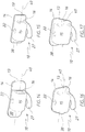
- the tube 19, may be generally circular in transverse cross-section as shown in Figure 10 , or may be oval or square in transverse cross-section. However, the tube 19 may be also provided with irregularities to aid in securing it to the portion 15. In the embodiment of Figure 8 , the tube 19 has transverse slots or grooves 35 within which the abovementioned settable substance hardens to aid in securing the tube 19 in position. In an alternative embodiment, the tube 19 may have a flattened portion 36 as shown in Figure 11 .
- the anchor assembly 30 can also be applied to the palatal surfaces of molars and pre-molars in various situations. It can be applied to first molars and used to then attach to a large diameter palatal wire 21 which transmits force through to a Nance button, either laboratory made, or made in situ from light cured composite.
- the anchorage 10 makes it a lot easier for the dentist or orthodontist to quickly construct his own Nance button without the time delay, inconvenience, cost and inaccuracy of having a laboratory product made.
- Nance buttons made in situ fit perfectly and generally more accurately than laboratory made products and get less food debris underneath and less bad taste/bad smell as a result.
- the anchor assembly 30 can be used to provide massive palatal anchorage in order to retract anterior dental segments such as Canine to canine, especially in cases of premolar extractions, or for retraction of teeth with excessive protrusion, such as in bimaxillary protrusive cases, and/or to retract segments of teeth such as pre-molars and canines to correct malaligned mid lines, or to distalize impacted canines without disturbing the existing symmetry or positive qualities of the existing dental arch due to abberent reciprocal forces.
- the use of the assembly 30 on the maxillary teeth provides such substantial anchorage that it can be used simultaneously to retract both maxillary arch teeth and mandibular teeth by running the appropriate interarch class two elastics.
- the assembly 10 can also be positioned on premolars or canines, and then engaged with a sufficiently large diameter and rigid wire traversing the hard palate in the region of the rugae, and with the aid of a laboratory made or in situ Nance button, can be used to provide substantial anchorage against which entire molar posterior segments can be distalized as a block.
- the assembly 10 can then be removed from the premolars and fitted to these distalized molars and a Nance button attached in order to simultaneously both prevent them spontaneously relapsing towards the mesial, and to provide a source of anchorage in order to use them to retract rotate or move the anterior or premolar segments in order to fill any space that has been created by distalizing the posterior segments.
- the assembly can be used for orthodontists and dentists who have provided optimal and comprehensive treatment and have moved the molars into the ideal position and relationship and who now desire them to be locked into that position, without the use of headgear or surgical devices such as implants or bone screws, with a minimal probability of mesial spontaneous drifting, and also to lock them in sufficiently to utilise them as anchorage units in order to retract or rotate or move other teeth in the dental arch, with minimal anchorage slip or untoward anchor teeth movement.
- Grooves 35 can be cut or stamped or cast into the primary tube. These grooves (19, 35) mechanically engage the cement and stop slippage of the tube 19 relative to the cement, and by extension, stop movement relative to the tooth, thus forming a rigid splint that stops any mesial tilting and minimises mesial drift.
- the rough cut edges are faced away from the cheek so as not to cause aggravation.
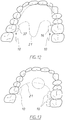
- FIG 12 there is schematically depicted a pair of the orthodontic anchors 10, with an orthodontic wire 21 extending therebetween.
- the wire 21 has end portions fixed in respective main passages 16 by the above described settable flowable substance.
- Nance assembly includes at least one anchor, and then optionally one or two anchors 10, with the wire 21 secured to each of the anchors 10 by the abovementioned flowable substance.
- the base 13 is of a plate configuration so as to have the surface 14 that engages the tooth, and a surface 38 adjacent the duct portion 15.
- the base 13 is arcuate so that the surface 38 is generally convex.
- the base 13 is generally planar, accordingly the surfaces 38 are generally flat.
- the passage 16 has the longitudinal axis 40, with the passage 16 preferably elongated in the direction transverse of the axis 40 but generally parallel to the surfaces 14 and 38.
- Each of the passages 16 has a transverse width, generally perpendicular to the surfaces 14 and 38, that is less than the width that is generally parallel to the surface 38.
- the passage 16 is dimensioned so that the wires (or other elongated element) can be positioned in the passage 16 in a desired position and orientation, and then fixed in that position. This has the advantage of providing the dentist with more latitude in respect of positioning the anchor 10. A still further advantage is that the passage 16 can accommodate wires 21 of different diameters.
- Grooves 35 can be cut or stamped or cast into the primary tube. These grooves (19, 35) mechanically engage the cement and stop slippage of the tube 19 relative to the cement, and by extension, stop movement relative to the tooth, thus forming a rigid splint that stops any mesial tilting and minimises mesial drift.
- the rough cut edges are faced away from the cheek so as not to cause aggravation.
- FIG 12 there is schematically depicted a pair of the orthodontic anchors 10, with an orthodontic wire 21 extending therebetween.
- the wire 21 has end portions fixed in respective main passages 16 by the above described settable flowable substance.
- Nance assembly includes at least one anchor, and then optionally one or two anchors 10, with the wire 21 secured to each of the anchors 10 by the abovementioned flowable substance.
- the base 13 is of a plate configuration so as to have the surface 14 that engages the tooth, and a surface 38 adjacent the duct portion 15.
- the base 13 is arcuate so that the surface 38 is generally convex.
- the base 13 is generally planar, accordingly the surfaces 38 are generally flat.
- the passage 16 has the longitudinal axis 40, with the passage 16 preferably elongated in the direction transverse of the axis 40 but generally parallel to the surfaces 14 and 38.
- Each of the passages 16 has a transverse width, generally perpendicular to the surfaces 14 and 38, that is less than the width that is generally parallel to the surface 38.
- the passage 16 is dimensioned so that the wires (or other elongated element) can be positioned in the passage 16 in a desired position and orientation, and then fixed in that position. This has the advantage of providing the dentist with more latitude in respect of positioning the anchor 10. A still further advantage is that the passage 16 can accommodate wires 21 of different diameters.
Landscapes
- Health & Medical Sciences (AREA)
- Oral & Maxillofacial Surgery (AREA)
- Dentistry (AREA)
- Epidemiology (AREA)
- Life Sciences & Earth Sciences (AREA)
- Animal Behavior & Ethology (AREA)
- General Health & Medical Sciences (AREA)
- Public Health (AREA)
- Veterinary Medicine (AREA)
- Dental Tools And Instruments Or Auxiliary Dental Instruments (AREA)
Claims (11)
- Ancrage orthodontique (10) comprenant :une base (13) ayant une surface de base à fixer à une surface de dent ; etun élément conduit (15) fixé à la base et se projetant depuis la base dans un sens éloigné de la surface, et fournissant un passage traversant (16) s'étendant généralement parallèle à la surface de base et dans lequel un élément orthodontique allongé (21) peut entrer et qui doit être fixé à l'élément conduit (15) et par conséquent à la base (13),caractérisé en ce que le passage (16) est un passage principal, et que l'élément conduit (15) comprend un passage de remplissage (22), le passage de remplissage (22) s'étendant vers le passage principal pour fournir l'administration d'un matériau fluide pouvant être fixé audit passage principal pour fixer l'élément (21) à l'élément conduit (15).
- Ancrage orthodontique selon la revendication 1, un tube (19) pouvant s'étendre à travers le passage (16), ayant une coupe transversale plus petite que celle du passage (16), de sorte qu'il existe un espace entre la surface longitudinale externe du tube (19) et la surface interne de l'élément conduit (15) entourant le passage (16), et un fil comme élément orthodontique allongé (21) étant disposé dans le tube (19).
- Ancrage orthodontique selon les revendications 1 ou 2, la base (13) et l'élément conduit (15) étant formés d'un seul tenant.
- Ancrage orthodontique selon les revendications 2 ou 3, le passage (16) ayant un axe longitudinal, et le passage (16) étant allongé dans un sens dudit axe et généralement parallèle à ladite surface.
- Ancrage orthodontique selon la revendication 4, le passage (16) ayant une largeur qui est transversale par rapport audit axe et généralement parallèle à ladite surface qui est supérieure à une largeur transversale qui est transversale pour ledit axe et transversale par rapport à ladite surface.
- Ancrage orthodontique selon les revendications 1 à 5, la base (13) étant une plaque qui est généralement plane ou qui est arquée afin de présenter une surface convexe adjacente à l'élément conduit.
- Ensemble d'ancrage orthodontique (30) comprenant l'ancrage orthodontique (10) selon l'une quelconque des revendications 1 à 6, l'ancrage orthodontique (10) étant une première ancre, avec l'ensemble comprenant un ancrage orthodontique (10) supplémentaire ;
l'ancrage orthodontique (10) supplémentaire comprenant :une base (11) ayant une surface de base à fixer à une surface de dent,un élément conduit (15) fixé à la base et se projetant depuis la base dans un sens éloigné de la surface de base, et fournissant un passage principal s'étendant généralement parallèle à la surface de base, etun tube (19) passant à travers le passage principal à travers lequel un élément orthodontique allongé (21) doit passer pour être solidement fixé à la surface de base par l'élément conduit (15) ;l'élément orthodontique allongé (21) du premier ancrage orthodontique (10) étant un tube (19), avec le tube étant un tube commun s'étendant entre les deux ancres. - Ensemble d'ancrage orthodontique selon la revendication 7, la base (11) et l'élément conduit (15) de l'ancrage orthodontique (10) supplémentaire étant formés d'un seul tenant.
- Ensemble d'ancrage orthodontique selon la revendication 7 ou 8, l'ancrage orthodontique (10) supplémentaire comprenant le matériau fluide pouvant être fixé localisé dans le passage principal afin d'être localisé entre le tube (19) et l'élément conduit (15), et qui peut être fixé pour solidement fixer le tube (19) à l'élément conduit (15).
- Ensemble d'ancrage orthodontique selon les revendications 7 à 9, le tube (19) de l'ancrage orthodontique (10) supplémentaire étant plastiquement déformable pour permettre la formation de courbes à localiser dans ledit passage principal.
- Ensemble d'ancrage orthodontique selon les revendications 7 à 10, le matériau fluide pouvant être fixé étant localisé dans chaque passage principal pour fixer solidement le tube commun à chaque base.
Applications Claiming Priority (2)
| Application Number | Priority Date | Filing Date | Title |
|---|---|---|---|
| AU2015903045A AU2015903045A0 (en) | 2015-07-31 | An orthodontic anchorage device | |
| PCT/AU2016/000250 WO2017020062A1 (fr) | 2015-07-31 | 2016-07-14 | Dispositif d'ancrage orthodontique |
Publications (3)
| Publication Number | Publication Date |
|---|---|
| EP3328312A1 EP3328312A1 (fr) | 2018-06-06 |
| EP3328312A4 EP3328312A4 (fr) | 2019-04-03 |
| EP3328312B1 true EP3328312B1 (fr) | 2020-09-09 |
Family
ID=57942109
Family Applications (1)
| Application Number | Title | Priority Date | Filing Date |
|---|---|---|---|
| EP16831956.4A Active EP3328312B1 (fr) | 2015-07-31 | 2016-07-14 | Dispositif d'ancrage orthodontique |
Country Status (6)
| Country | Link |
|---|---|
| US (2) | US20180228576A1 (fr) |
| EP (1) | EP3328312B1 (fr) |
| CN (1) | CN108135673B (fr) |
| AU (1) | AU2016302381B2 (fr) |
| CA (1) | CA2994022C (fr) |
| WO (1) | WO2017020062A1 (fr) |
Families Citing this family (4)
| Publication number | Priority date | Publication date | Assignee | Title |
|---|---|---|---|---|
| WO2019217993A1 (fr) * | 2018-05-14 | 2019-11-21 | Erskine Holdco Pty Ltd | Dispositif d'ancrage orthodontique |
| US20220202535A2 (en) * | 2018-05-14 | 2022-06-30 | Erskine Holdco Pty Ltd | An orthodontic anchorage assembly |
| WO2020220095A1 (fr) * | 2019-05-01 | 2020-11-05 | Erskine Holdco Pty Ltd | Procédés et dispositifs orthodontiques |
| US12594149B2 (en) * | 2023-03-08 | 2026-04-07 | Clayton M. Fulks | Orthodontic tube system |
Family Cites Families (34)
| Publication number | Priority date | Publication date | Assignee | Title |
|---|---|---|---|---|
| US3238619A (en) * | 1963-04-29 | 1966-03-08 | Rocky Mouutain Dental Products | Arch wire locking device for orthodontic bracket |
| US3494034A (en) * | 1968-06-12 | 1970-02-10 | Peter C Kesling | Buccal tube insert |
| US4249898A (en) * | 1979-11-09 | 1981-02-10 | "A"-Company, Inc. | Orthodontic rotation spring |
| US5320526A (en) * | 1992-12-10 | 1994-06-14 | American Orthodontics | Buccal tube insert |
| JP3547262B2 (ja) * | 1996-07-25 | 2004-07-28 | セイコーエプソン株式会社 | バッカルチューブ及びバッカルチューブの製造方法 |
| EP0931518A1 (fr) * | 1997-05-16 | 1999-07-28 | Shofu Inc. | Dispositif orthodontique |
| US6053729A (en) * | 1998-03-02 | 2000-04-25 | Ortho Corporation | Unitary substantially nickel free alloy injection molded orthodontic bracket |
| ES2154179B1 (es) * | 1998-09-30 | 2001-11-16 | Rainer Brandt | Soporte ortodoncico de ranura variable. |
| US6280185B1 (en) * | 2000-06-16 | 2001-08-28 | 3M Innovative Properties Company | Orthodontic appliance with improved precipitation hardening martensitic alloy |
| JP4375889B2 (ja) * | 2000-08-29 | 2009-12-02 | 野田 隆夫 | 小臼歯用チューブ |
| US6733285B2 (en) * | 2001-12-14 | 2004-05-11 | 3M Innovative Properties Company | Orthodontic appliance with lingual retaining groove |
| US6733287B2 (en) * | 2002-03-06 | 2004-05-11 | Michael K. Wilkerson | Molar tube lock |
| US20040265768A1 (en) * | 2003-06-07 | 2004-12-30 | Tuneberg Lee H. | Buccal tube |
| US7713057B2 (en) * | 2005-01-10 | 2010-05-11 | De Salazar Vinas Maria Pilar | Oral mucous membrane protector for orthodontic applications |
| CN2882563Y (zh) * | 2006-01-15 | 2007-03-28 | 郑伟 | 一种牙矫正器 |
| WO2008031060A2 (fr) * | 2006-09-07 | 2008-03-13 | Rmo, Inc. | Tube buccal à frottement réduit et procédé d'utilisation |
| CN201022751Y (zh) * | 2007-04-30 | 2008-02-20 | 钟小龙 | 一种有“l”形楔压件的口腔正畸用的游离牵引钩 |
| AU2009238317B2 (en) * | 2008-11-14 | 2011-10-06 | Ormco Corporation | Surface treated polycrystalline ceramic orthodontic bracket and method of making same |
| US20100323315A1 (en) * | 2009-06-23 | 2010-12-23 | Kyoto Takemoto | Orthodontic bracket |
| CN201453387U (zh) * | 2009-07-06 | 2010-05-12 | 王建均 | 牙齿正畸主动自锁托槽 |
| US20110053108A1 (en) * | 2009-08-26 | 2011-03-03 | Ariza Joaquin T | System of tube and resin for orthodontics |
| CN102113917A (zh) * | 2010-03-10 | 2011-07-06 | 千吉文 | 活动牙齿矫治器及制作方法 |
| KR101234205B1 (ko) | 2010-11-18 | 2013-02-18 | 휴비트 주식회사 | 치열 교정치료용 튜브 |
| EP2540252A4 (fr) * | 2011-01-21 | 2015-01-28 | Toshiaki Hiro | Support orthodontique |
| FR2972342A1 (fr) | 2011-03-11 | 2012-09-14 | Stephan Valero | Dispositif pour relier un arc orthodontique avec une dent |
| JP2012210378A (ja) * | 2011-03-31 | 2012-11-01 | Sakuranomiya Kagaku Kk | 塗料被覆歯科用金属製品 |
| KR20120115044A (ko) * | 2011-04-09 | 2012-10-17 | 홍순호 | 치아교정용 구멍 브라켓. |
| CN102228397B (zh) * | 2011-06-23 | 2012-12-05 | 广州瑞通生物科技有限公司 | 一种带正轴功能的个性化正畸矫治器 |
| EP2827795A4 (fr) | 2012-03-23 | 2015-11-18 | Joaquín T Ariza | Tube pour orthodontie |
| CN202724009U (zh) * | 2012-07-30 | 2013-02-13 | 赵计林 | 矫正上磨牙伸长的固定式磨牙压低器 |
| US8550814B1 (en) * | 2012-08-16 | 2013-10-08 | Monte Collins | Multi-component orthodontic bracket assembly |
| WO2014165726A1 (fr) * | 2013-04-05 | 2014-10-09 | Cassalia Benjamin | Appareil et procédé d'alignement de fils orthodontiques |
| CN104783912B (zh) * | 2015-03-30 | 2023-06-09 | 高原 | 用于牙齿内侧的矫正牙套制作方法及牙齿矫正组合器件 |
| CN205126459U (zh) * | 2015-11-09 | 2016-04-06 | 武广增 | 折叠式弹力扩展辅弓 |
-
2016
- 2016-07-14 EP EP16831956.4A patent/EP3328312B1/fr active Active
- 2016-07-14 US US15/749,333 patent/US20180228576A1/en not_active Abandoned
- 2016-07-14 WO PCT/AU2016/000250 patent/WO2017020062A1/fr not_active Ceased
- 2016-07-14 AU AU2016302381A patent/AU2016302381B2/en not_active Ceased
- 2016-07-14 CN CN201680056809.3A patent/CN108135673B/zh not_active Expired - Fee Related
- 2016-07-14 CA CA2994022A patent/CA2994022C/fr active Active
-
2022
- 2022-06-21 US US17/845,080 patent/US20220387142A1/en not_active Abandoned
Non-Patent Citations (1)
| Title |
|---|
| None * |
Also Published As
| Publication number | Publication date |
|---|---|
| AU2016302381B2 (en) | 2021-04-29 |
| CN108135673A (zh) | 2018-06-08 |
| WO2017020062A1 (fr) | 2017-02-09 |
| AU2016302381A1 (en) | 2018-02-22 |
| EP3328312A1 (fr) | 2018-06-06 |
| EP3328312A4 (fr) | 2019-04-03 |
| US20180228576A1 (en) | 2018-08-16 |
| CA2994022A1 (fr) | 2017-02-09 |
| CN108135673B (zh) | 2021-06-22 |
| US20220387142A1 (en) | 2022-12-08 |
| CA2994022C (fr) | 2023-10-03 |
Similar Documents
| Publication | Publication Date | Title |
|---|---|---|
| US20220387142A1 (en) | Orthodontic anchorage device | |
| KR102511765B1 (ko) | 가변 크기의 아치와이어 슬롯을 갖는 치과교정 시스템 | |
| US5580243A (en) | Removable orthodontic aligner with eyelet arm springs | |
| US5374187A (en) | Orthodontic appliance | |
| EP3367956B2 (fr) | Verrou orthodontique à élément coulissant de distalisation pour molaire | |
| US20150305832A1 (en) | System for moving and aligning teeth | |
| US11382722B2 (en) | Orthodontic brackets for deciduous teeth | |
| EP3801363B1 (fr) | Ensemble d'ancrage orthodontique | |
| US11730570B2 (en) | Bracket | |
| US9370407B1 (en) | Canine tooth traction device and method | |
| US20220233277A1 (en) | Orthodontic methods and devices | |
| WO2019217993A1 (fr) | Dispositif d'ancrage orthodontique | |
| Wilmes | The beneslider and pendulum B appliances | |
| Schupak et al. | Esthetics and orthodontics | |
| Alali | Fixed lingual mandibular growth modificator: A new appliance for class II correction | |
| Papadopoulos | 30 The Advanced Molar Distalization Appliance | |
| Cozzani et al. | The Distal Screw: a modified Distal Jet | |
| Joshi | Treatment of a Class II Division I malocclusion using miniscrews: A case report | |
| Hossain | Treatment technique: A clinical & Practical sequences in the Management of Angle Class II Malocclusion (Maxillary Protrusion) | |
| De Clerck et al. | 22 Distalization of the maxillary arch with | |
| Kassir et al. | Orthodontic management of an originally surgically planned treatment of an open bite: A case report | |
| Glauser | Preventive Orthodontics and Limited Treatment Procedures: Manual |
Legal Events
| Date | Code | Title | Description |
|---|---|---|---|
| STAA | Information on the status of an ep patent application or granted ep patent |
Free format text: STATUS: THE INTERNATIONAL PUBLICATION HAS BEEN MADE |
|
| PUAI | Public reference made under article 153(3) epc to a published international application that has entered the european phase |
Free format text: ORIGINAL CODE: 0009012 |
|
| STAA | Information on the status of an ep patent application or granted ep patent |
Free format text: STATUS: REQUEST FOR EXAMINATION WAS MADE |
|
| 17P | Request for examination filed |
Effective date: 20180216 |
|
| AK | Designated contracting states |
Kind code of ref document: A1 Designated state(s): AL AT BE BG CH CY CZ DE DK EE ES FI FR GB GR HR HU IE IS IT LI LT LU LV MC MK MT NL NO PL PT RO RS SE SI SK SM TR |
|
| AX | Request for extension of the european patent |
Extension state: BA ME |
|
| DAV | Request for validation of the european patent (deleted) | ||
| DAX | Request for extension of the european patent (deleted) | ||
| A4 | Supplementary search report drawn up and despatched |
Effective date: 20190306 |
|
| RIC1 | Information provided on ipc code assigned before grant |
Ipc: A61C 7/28 20060101AFI20190228BHEP |
|
| GRAP | Despatch of communication of intention to grant a patent |
Free format text: ORIGINAL CODE: EPIDOSNIGR1 |
|
| STAA | Information on the status of an ep patent application or granted ep patent |
Free format text: STATUS: GRANT OF PATENT IS INTENDED |
|
| INTG | Intention to grant announced |
Effective date: 20200330 |
|
| GRAS | Grant fee paid |
Free format text: ORIGINAL CODE: EPIDOSNIGR3 |
|
| GRAA | (expected) grant |
Free format text: ORIGINAL CODE: 0009210 |
|
| STAA | Information on the status of an ep patent application or granted ep patent |
Free format text: STATUS: THE PATENT HAS BEEN GRANTED |
|
| AK | Designated contracting states |
Kind code of ref document: B1 Designated state(s): AL AT BE BG CH CY CZ DE DK EE ES FI FR GB GR HR HU IE IS IT LI LT LU LV MC MK MT NL NO PL PT RO RS SE SI SK SM TR |
|
| REG | Reference to a national code |
Ref country code: GB Ref legal event code: FG4D |
|
| REG | Reference to a national code |
Ref country code: AT Ref legal event code: REF Ref document number: 1310606 Country of ref document: AT Kind code of ref document: T Effective date: 20200915 Ref country code: CH Ref legal event code: EP |
|
| REG | Reference to a national code |
Ref country code: DE Ref legal event code: R096 Ref document number: 602016043848 Country of ref document: DE |
|
| REG | Reference to a national code |
Ref country code: IE Ref legal event code: FG4D |
|
| REG | Reference to a national code |
Ref country code: CH Ref legal event code: NV Representative=s name: BOVARD AG PATENT- UND MARKENANWAELTE, CH |
|
| REG | Reference to a national code |
Ref country code: NL Ref legal event code: FP |
|
| REG | Reference to a national code |
Ref country code: LT Ref legal event code: MG4D |
|
| PG25 | Lapsed in a contracting state [announced via postgrant information from national office to epo] |
Ref country code: GR Free format text: LAPSE BECAUSE OF FAILURE TO SUBMIT A TRANSLATION OF THE DESCRIPTION OR TO PAY THE FEE WITHIN THE PRESCRIBED TIME-LIMIT Effective date: 20201210 Ref country code: HR Free format text: LAPSE BECAUSE OF FAILURE TO SUBMIT A TRANSLATION OF THE DESCRIPTION OR TO PAY THE FEE WITHIN THE PRESCRIBED TIME-LIMIT Effective date: 20200909 Ref country code: LT Free format text: LAPSE BECAUSE OF FAILURE TO SUBMIT A TRANSLATION OF THE DESCRIPTION OR TO PAY THE FEE WITHIN THE PRESCRIBED TIME-LIMIT Effective date: 20200909 Ref country code: BG Free format text: LAPSE BECAUSE OF FAILURE TO SUBMIT A TRANSLATION OF THE DESCRIPTION OR TO PAY THE FEE WITHIN THE PRESCRIBED TIME-LIMIT Effective date: 20201209 Ref country code: SE Free format text: LAPSE BECAUSE OF FAILURE TO SUBMIT A TRANSLATION OF THE DESCRIPTION OR TO PAY THE FEE WITHIN THE PRESCRIBED TIME-LIMIT Effective date: 20200909 Ref country code: FI Free format text: LAPSE BECAUSE OF FAILURE TO SUBMIT A TRANSLATION OF THE DESCRIPTION OR TO PAY THE FEE WITHIN THE PRESCRIBED TIME-LIMIT Effective date: 20200909 Ref country code: NO Free format text: LAPSE BECAUSE OF FAILURE TO SUBMIT A TRANSLATION OF THE DESCRIPTION OR TO PAY THE FEE WITHIN THE PRESCRIBED TIME-LIMIT Effective date: 20201209 |
|
| REG | Reference to a national code |
Ref country code: AT Ref legal event code: MK05 Ref document number: 1310606 Country of ref document: AT Kind code of ref document: T Effective date: 20200909 |
|
| PG25 | Lapsed in a contracting state [announced via postgrant information from national office to epo] |
Ref country code: RS Free format text: LAPSE BECAUSE OF FAILURE TO SUBMIT A TRANSLATION OF THE DESCRIPTION OR TO PAY THE FEE WITHIN THE PRESCRIBED TIME-LIMIT Effective date: 20200909 Ref country code: LV Free format text: LAPSE BECAUSE OF FAILURE TO SUBMIT A TRANSLATION OF THE DESCRIPTION OR TO PAY THE FEE WITHIN THE PRESCRIBED TIME-LIMIT Effective date: 20200909 Ref country code: PL Free format text: LAPSE BECAUSE OF FAILURE TO SUBMIT A TRANSLATION OF THE DESCRIPTION OR TO PAY THE FEE WITHIN THE PRESCRIBED TIME-LIMIT Effective date: 20200909 |
|
| PG25 | Lapsed in a contracting state [announced via postgrant information from national office to epo] |
Ref country code: PT Free format text: LAPSE BECAUSE OF FAILURE TO SUBMIT A TRANSLATION OF THE DESCRIPTION OR TO PAY THE FEE WITHIN THE PRESCRIBED TIME-LIMIT Effective date: 20210111 Ref country code: RO Free format text: LAPSE BECAUSE OF FAILURE TO SUBMIT A TRANSLATION OF THE DESCRIPTION OR TO PAY THE FEE WITHIN THE PRESCRIBED TIME-LIMIT Effective date: 20200909 Ref country code: CZ Free format text: LAPSE BECAUSE OF FAILURE TO SUBMIT A TRANSLATION OF THE DESCRIPTION OR TO PAY THE FEE WITHIN THE PRESCRIBED TIME-LIMIT Effective date: 20200909 Ref country code: SM Free format text: LAPSE BECAUSE OF FAILURE TO SUBMIT A TRANSLATION OF THE DESCRIPTION OR TO PAY THE FEE WITHIN THE PRESCRIBED TIME-LIMIT Effective date: 20200909 Ref country code: EE Free format text: LAPSE BECAUSE OF FAILURE TO SUBMIT A TRANSLATION OF THE DESCRIPTION OR TO PAY THE FEE WITHIN THE PRESCRIBED TIME-LIMIT Effective date: 20200909 |
|
| PG25 | Lapsed in a contracting state [announced via postgrant information from national office to epo] |
Ref country code: IS Free format text: LAPSE BECAUSE OF FAILURE TO SUBMIT A TRANSLATION OF THE DESCRIPTION OR TO PAY THE FEE WITHIN THE PRESCRIBED TIME-LIMIT Effective date: 20210109 Ref country code: ES Free format text: LAPSE BECAUSE OF FAILURE TO SUBMIT A TRANSLATION OF THE DESCRIPTION OR TO PAY THE FEE WITHIN THE PRESCRIBED TIME-LIMIT Effective date: 20200909 Ref country code: AT Free format text: LAPSE BECAUSE OF FAILURE TO SUBMIT A TRANSLATION OF THE DESCRIPTION OR TO PAY THE FEE WITHIN THE PRESCRIBED TIME-LIMIT Effective date: 20200909 Ref country code: AL Free format text: LAPSE BECAUSE OF FAILURE TO SUBMIT A TRANSLATION OF THE DESCRIPTION OR TO PAY THE FEE WITHIN THE PRESCRIBED TIME-LIMIT Effective date: 20200909 |
|
| REG | Reference to a national code |
Ref country code: DE Ref legal event code: R097 Ref document number: 602016043848 Country of ref document: DE |
|
| PG25 | Lapsed in a contracting state [announced via postgrant information from national office to epo] |
Ref country code: SK Free format text: LAPSE BECAUSE OF FAILURE TO SUBMIT A TRANSLATION OF THE DESCRIPTION OR TO PAY THE FEE WITHIN THE PRESCRIBED TIME-LIMIT Effective date: 20200909 |
|
| PLBE | No opposition filed within time limit |
Free format text: ORIGINAL CODE: 0009261 |
|
| STAA | Information on the status of an ep patent application or granted ep patent |
Free format text: STATUS: NO OPPOSITION FILED WITHIN TIME LIMIT |
|
| 26N | No opposition filed |
Effective date: 20210610 |
|
| PG25 | Lapsed in a contracting state [announced via postgrant information from national office to epo] |
Ref country code: SI Free format text: LAPSE BECAUSE OF FAILURE TO SUBMIT A TRANSLATION OF THE DESCRIPTION OR TO PAY THE FEE WITHIN THE PRESCRIBED TIME-LIMIT Effective date: 20200909 Ref country code: DK Free format text: LAPSE BECAUSE OF FAILURE TO SUBMIT A TRANSLATION OF THE DESCRIPTION OR TO PAY THE FEE WITHIN THE PRESCRIBED TIME-LIMIT Effective date: 20200909 |
|
| PG25 | Lapsed in a contracting state [announced via postgrant information from national office to epo] |
Ref country code: IT Free format text: LAPSE BECAUSE OF FAILURE TO SUBMIT A TRANSLATION OF THE DESCRIPTION OR TO PAY THE FEE WITHIN THE PRESCRIBED TIME-LIMIT Effective date: 20200909 |
|
| PG25 | Lapsed in a contracting state [announced via postgrant information from national office to epo] |
Ref country code: MC Free format text: LAPSE BECAUSE OF FAILURE TO SUBMIT A TRANSLATION OF THE DESCRIPTION OR TO PAY THE FEE WITHIN THE PRESCRIBED TIME-LIMIT Effective date: 20200909 |
|
| PG25 | Lapsed in a contracting state [announced via postgrant information from national office to epo] |
Ref country code: LU Free format text: LAPSE BECAUSE OF NON-PAYMENT OF DUE FEES Effective date: 20210714 |
|
| PG25 | Lapsed in a contracting state [announced via postgrant information from national office to epo] |
Ref country code: HU Free format text: LAPSE BECAUSE OF FAILURE TO SUBMIT A TRANSLATION OF THE DESCRIPTION OR TO PAY THE FEE WITHIN THE PRESCRIBED TIME-LIMIT; INVALID AB INITIO Effective date: 20160714 |
|
| PG25 | Lapsed in a contracting state [announced via postgrant information from national office to epo] |
Ref country code: CY Free format text: LAPSE BECAUSE OF FAILURE TO SUBMIT A TRANSLATION OF THE DESCRIPTION OR TO PAY THE FEE WITHIN THE PRESCRIBED TIME-LIMIT Effective date: 20200909 |
|
| PGFP | Annual fee paid to national office [announced via postgrant information from national office to epo] |
Ref country code: NL Payment date: 20230728 Year of fee payment: 8 |
|
| PGFP | Annual fee paid to national office [announced via postgrant information from national office to epo] |
Ref country code: IE Payment date: 20230725 Year of fee payment: 8 Ref country code: GB Payment date: 20230713 Year of fee payment: 8 Ref country code: CH Payment date: 20230802 Year of fee payment: 8 |
|
| PGFP | Annual fee paid to national office [announced via postgrant information from national office to epo] |
Ref country code: FR Payment date: 20230721 Year of fee payment: 8 Ref country code: DE Payment date: 20230718 Year of fee payment: 8 Ref country code: BE Payment date: 20230719 Year of fee payment: 8 |
|
| PG25 | Lapsed in a contracting state [announced via postgrant information from national office to epo] |
Ref country code: MK Free format text: LAPSE BECAUSE OF FAILURE TO SUBMIT A TRANSLATION OF THE DESCRIPTION OR TO PAY THE FEE WITHIN THE PRESCRIBED TIME-LIMIT Effective date: 20200909 |
|
| PG25 | Lapsed in a contracting state [announced via postgrant information from national office to epo] |
Ref country code: TR Free format text: LAPSE BECAUSE OF FAILURE TO SUBMIT A TRANSLATION OF THE DESCRIPTION OR TO PAY THE FEE WITHIN THE PRESCRIBED TIME-LIMIT Effective date: 20200909 |
|
| PG25 | Lapsed in a contracting state [announced via postgrant information from national office to epo] |
Ref country code: MT Free format text: LAPSE BECAUSE OF FAILURE TO SUBMIT A TRANSLATION OF THE DESCRIPTION OR TO PAY THE FEE WITHIN THE PRESCRIBED TIME-LIMIT Effective date: 20200909 |
|
| REG | Reference to a national code |
Ref country code: DE Ref legal event code: R119 Ref document number: 602016043848 Country of ref document: DE |
|
| REG | Reference to a national code |
Ref country code: CH Ref legal event code: PL |
|
| REG | Reference to a national code |
Ref country code: NL Ref legal event code: MM Effective date: 20240801 |
|
| GBPC | Gb: european patent ceased through non-payment of renewal fee |
Effective date: 20240714 |
|
| PG25 | Lapsed in a contracting state [announced via postgrant information from national office to epo] |
Ref country code: DE Free format text: LAPSE BECAUSE OF NON-PAYMENT OF DUE FEES Effective date: 20250201 |
|
| PG25 | Lapsed in a contracting state [announced via postgrant information from national office to epo] |
Ref country code: NL Free format text: LAPSE BECAUSE OF NON-PAYMENT OF DUE FEES Effective date: 20240801 |
|
| PG25 | Lapsed in a contracting state [announced via postgrant information from national office to epo] |
Ref country code: CH Free format text: LAPSE BECAUSE OF NON-PAYMENT OF DUE FEES Effective date: 20240731 Ref country code: BE Free format text: LAPSE BECAUSE OF NON-PAYMENT OF DUE FEES Effective date: 20240731 |
|
| PG25 | Lapsed in a contracting state [announced via postgrant information from national office to epo] |
Ref country code: FR Free format text: LAPSE BECAUSE OF NON-PAYMENT OF DUE FEES Effective date: 20240731 |
|
| PG25 | Lapsed in a contracting state [announced via postgrant information from national office to epo] |
Ref country code: GB Free format text: LAPSE BECAUSE OF NON-PAYMENT OF DUE FEES Effective date: 20240714 |
|
| REG | Reference to a national code |
Ref country code: BE Ref legal event code: MM Effective date: 20240731 |
|
| PG25 | Lapsed in a contracting state [announced via postgrant information from national office to epo] |
Ref country code: IE Free format text: LAPSE BECAUSE OF NON-PAYMENT OF DUE FEES Effective date: 20240714 |