EP3328563B1 - Walzgerüst zum walzen von walzgut - Google Patents
Walzgerüst zum walzen von walzgut Download PDFInfo
- Publication number
- EP3328563B1 EP3328563B1 EP16744396.9A EP16744396A EP3328563B1 EP 3328563 B1 EP3328563 B1 EP 3328563B1 EP 16744396 A EP16744396 A EP 16744396A EP 3328563 B1 EP3328563 B1 EP 3328563B1
- Authority
- EP
- European Patent Office
- Prior art keywords
- pressure
- roll
- chock
- low
- pressure pump
- Prior art date
- Legal status (The legal status is an assumption and is not a legal conclusion. Google has not performed a legal analysis and makes no representation as to the accuracy of the status listed.)
- Not-in-force
Links
- 238000005096 rolling process Methods 0.000 title claims description 39
- 239000000314 lubricant Substances 0.000 claims description 28
- 239000002826 coolant Substances 0.000 claims description 25
- 230000005540 biological transmission Effects 0.000 claims description 15
- 241001397809 Hakea leucoptera Species 0.000 claims description 5
- 230000008878 coupling Effects 0.000 claims description 3
- 238000010168 coupling process Methods 0.000 claims description 3
- 238000005859 coupling reaction Methods 0.000 claims description 3
- 239000000463 material Substances 0.000 claims 1
- 210000003739 neck Anatomy 0.000 description 34
- 238000009434 installation Methods 0.000 description 7
- 238000001816 cooling Methods 0.000 description 3
- 230000004308 accommodation Effects 0.000 description 1
- 238000004891 communication Methods 0.000 description 1
- 238000010276 construction Methods 0.000 description 1
- 230000000694 effects Effects 0.000 description 1
- 239000012530 fluid Substances 0.000 description 1
- 230000002706 hydrostatic effect Effects 0.000 description 1
- 238000005461 lubrication Methods 0.000 description 1
- 238000000034 method Methods 0.000 description 1
- 238000000926 separation method Methods 0.000 description 1
- 238000011144 upstream manufacturing Methods 0.000 description 1
Images



Classifications
-
- B—PERFORMING OPERATIONS; TRANSPORTING
- B21—MECHANICAL METAL-WORKING WITHOUT ESSENTIALLY REMOVING MATERIAL; PUNCHING METAL
- B21B—ROLLING OF METAL
- B21B31/00—Rolling stand structures; Mounting, adjusting, or interchanging rolls, roll mountings, or stand frames
- B21B31/07—Adaptation of roll neck bearings
- B21B31/076—Cooling; Lubricating roller bearings
-
- B—PERFORMING OPERATIONS; TRANSPORTING
- B21—MECHANICAL METAL-WORKING WITHOUT ESSENTIALLY REMOVING MATERIAL; PUNCHING METAL
- B21B—ROLLING OF METAL
- B21B31/00—Rolling stand structures; Mounting, adjusting, or interchanging rolls, roll mountings, or stand frames
- B21B31/07—Adaptation of roll neck bearings
- B21B31/074—Oil film bearings, e.g. "Morgoil" bearings
-
- B—PERFORMING OPERATIONS; TRANSPORTING
- B21—MECHANICAL METAL-WORKING WITHOUT ESSENTIALLY REMOVING MATERIAL; PUNCHING METAL
- B21B—ROLLING OF METAL
- B21B2203/00—Auxiliary arrangements, devices or methods in combination with rolling mills or rolling methods
- B21B2203/24—Hydrostatic bearings or guides
-
- B—PERFORMING OPERATIONS; TRANSPORTING
- B21—MECHANICAL METAL-WORKING WITHOUT ESSENTIALLY REMOVING MATERIAL; PUNCHING METAL
- B21B—ROLLING OF METAL
- B21B2203/00—Auxiliary arrangements, devices or methods in combination with rolling mills or rolling methods
- B21B2203/26—Motors, drives
-
- F—MECHANICAL ENGINEERING; LIGHTING; HEATING; WEAPONS; BLASTING
- F16—ENGINEERING ELEMENTS AND UNITS; GENERAL MEASURES FOR PRODUCING AND MAINTAINING EFFECTIVE FUNCTIONING OF MACHINES OR INSTALLATIONS; THERMAL INSULATION IN GENERAL
- F16C—SHAFTS; FLEXIBLE SHAFTS; ELEMENTS OR CRANKSHAFT MECHANISMS; ROTARY BODIES OTHER THAN GEARING ELEMENTS; BEARINGS
- F16C2322/00—Apparatus used in shaping articles
- F16C2322/12—Rolling apparatus, e.g. rolling stands, rolls
-
- F—MECHANICAL ENGINEERING; LIGHTING; HEATING; WEAPONS; BLASTING
- F16—ENGINEERING ELEMENTS AND UNITS; GENERAL MEASURES FOR PRODUCING AND MAINTAINING EFFECTIVE FUNCTIONING OF MACHINES OR INSTALLATIONS; THERMAL INSULATION IN GENERAL
- F16C—SHAFTS; FLEXIBLE SHAFTS; ELEMENTS OR CRANKSHAFT MECHANISMS; ROTARY BODIES OTHER THAN GEARING ELEMENTS; BEARINGS
- F16C32/00—Bearings not otherwise provided for
- F16C32/06—Bearings not otherwise provided for with moving member supported by a fluid cushion formed, at least to a large extent, otherwise than by movement of the shaft, e.g. hydrostatic air-cushion bearings
- F16C32/0629—Bearings not otherwise provided for with moving member supported by a fluid cushion formed, at least to a large extent, otherwise than by movement of the shaft, e.g. hydrostatic air-cushion bearings supported by a liquid cushion, e.g. oil cushion
Definitions
- the invention relates to a roll stand for rolling preferably metallic rolling stock.
- Such rolling stands are basically known in the art, for. B. from the WO 2013/048836 A1 ,
- the rolling stand for rolling metallic stock disclosed therein discloses a roll with two roll necks which are each rotatably mounted in a chock, also called a bearing housing.
- the storage of the roll neck in highly loaded scaffolding takes place in each case a cylindrical receiving space in the chock, wherein the receiving space of the chocks in the region of maximum load at least one high-pressure inlet, typically also with hydrostatic pockets, for cooling and / or lubricant in the receiving space.
- the known rolling mill has an inlet side connected to a low pressure circuit for the coolant and / or lubricant high pressure pump.
- the high-pressure inlet is arranged on the wall of the receiving space or in the wall of a bearing bush of the chock in the region of maximum load.
- the said low-pressure circuit for the coolant and / or lubricant comprises a low-pressure pump and a tank for the coolant or lubricant, which are both typically arranged below the roll stand.
- Low-pressure lines which are typically guided along the stator windows of the roll stand, connect the low-pressure pump to the low-pressure feeds in the receiving space of the roll neck plug, these low-pressure feeds typically also being distributed at 90 ° and 270 ° positions around the circumference of the receiving space.
- the Supplying the receiving space or the annular gap between the chock and the roll neck mounted therein with coolant and / or lubricant under low pressure, ie for example 2 bar, is generally sufficient for a lubrication of the roll neck with low rolling force.
- the low pressure is usually not sufficient to a separation, d. H. to realize a lifting of the roll neck of the chock or the bushing in the rolling operation; This has the consequence that the rotating roll neck contacts the chock or the bushing and, when rotating, rubs against the inside of the receiving space. The result is an undesirable wear of both the bushing as well as the pin and the pin bushing.
- the prior art provides said high-pressure pump, which is supplied on the input side via the low-pressure lines with the same coolant and / or lubricant, as it is used in the low-pressure circuit.
- the high pressure pump sets this supplied coolant and / or lubricant on the output side under high pressure, typically greater than 1,000 bar, preferably about 1,500 bar. From the high pressure pump, the coolant and / or lubricant via high pressure lines and said high pressure inlet in the region of maximum load in the receiving space, more precisely, pressed into the annular gap between the roll neck and chock. With the high pressure, it is possible to separate the roll neck and thus the roller, even at high rolling forces of the chock and to let the roll neck slide on a film formed from the coolant and / or lubricant virtually under high load friction.
- the invention has the object of developing a known rolling stand for rolling rolling to the effect that the cost of driving the high-pressure pump can be reduced.
- the claimed transmission has the advantage that the high pressure pump is driven by the roll neck when it rotates.
- a separate drive typically an electric motor for the high pressure pump is dispensable; its cost and the cost of electronic or hydraulic supply lines for the drive can be saved.
- the transmission is designed as a gear transmission, with a pinion and a drive wheel, which are directly or indirectly coupled with each other.
- the pinion is rotatably mounted on the drive shaft of the high pressure pump or the free end of the drive shaft is itself designed as a pinion.
- the drive wheel is designed as an externally toothed ring gear, which is preferably connected to the ball-distant side in a rotationally fixed manner with the roll neck or with a pin bush rotatably mounted on the roll neck.
- the High pressure pump is then arranged so that the pinion of its drive shaft with the externally toothed ring gear is preferably directly, ie without the interposition of other gears engaged. If a certain ratio is required, of course, more gears can be interposed.
- the high pressure pump can advantageously be installed to save space in a niche of the chock.
- a second variant of the transmission provides that the drive wheel is designed as an internally toothed ring gear, which is non-rotatably connected to the bale remote end face of the roll neck and preferably coaxially connected thereto.
- the high pressure pump is then arranged upstream of the end face of the roll neck in the axial direction such that the pinion of the drive shaft of the high pressure pump preferably engages directly with the internally toothed ring gear.
- the expression that the pinion engages directly with the drive wheel means that the teeth of the pinion mesh with the teeth of the drive wheel.
- the low pressure inlet is supplied by a low pressure circuit for the coolant and / or lubricant.
- the low-pressure circuit has a low-pressure pump and at least one low-pressure line with a branch in order to supply both the low-pressure inlets and the low-pressure inlet side of the high-pressure pump with coolant and / or lubricant.
- the diversion of the low-pressure line for the low-pressure inlet and the high-pressure pump can be arranged outside the chock, then preferably at the level of the chock, directly to the low pressure line running along the stand of the rolling mill. In this case, two low-pressure lines go from the junction into the chock.
- the branch may be realized inside the chock.
- this line then branches to the low pressure inlet and the high pressure inlet.
- This second variant for the branch has the advantage that, as I said, only a low-pressure line goes into the chock and thus when a roll change only this one line must be separated or connected. The risk that a line is not re-coupled after a roll change is thereby reduced.
- both the low pressure and the high-pressure feeds for the coolant and / or lubricant are formed in the bearing bush. These feeds are then in fluid communication with the corresponding channels in the chock.
- FIG. 1 shows in schematic form a roll stand according to the invention in quarto construction, ie with four superimposed rollers.
- Both both middle rollers are work rolls 170 which typically span a nip between which rolling stock is conveyed and rolled in the rolling direction R.
- the two work rolls 170 are supported by an upper and a lower support roller 110.
- the support rollers are rotatably mounted with their roll neck 112 in chocks 120.
- the chocks 120 also called bearing housing, have a cylindrical, possibly also conical receiving space 122, in which the respective roll neck 112 of the support rollers 110 are rotatably mounted.
- the receiving space 122 can be clamped by a bearing bush 128, which is arranged rotationally fixed in the chock.
- annular gap is formed, which is filled with cooling and / or lubricant during operation of the roll stand.
- supply and drainages for the coolant and / or lubricant are provided on the periphery of the receiving space.
- at least one high-pressure inlet 124 is arranged, via which the coolant and / or lubricant is forced into the annular gap with the aid of a high-pressure pump 130 if necessary under high pressure, typically greater than 1,000 bar, preferably 1,500 bar.
- there is at least one low-pressure inlet 126 which is typically arranged in the region of a 90 ° or 270 ° position.
- a low pressure circuit 150 is assigned.
- the low-pressure circuit comprises a low-pressure pump 152 for providing the coolant and / or lubricant at low pressure, for example 1 to 10 bar, preferably 2 bar.
- the low pressure pump 152 pumps the coolant and / or lubricant from a tank, which is typically below the rolling stand, in a low pressure line 154.
- a first Variant as in FIG.
- a pressure regulator 158 provides the necessary form in the low pressure line 154, which are connected to the chocks.
- the high-pressure pump 130 is arranged in or at least in the region of the chock 120. This applies both to the chock of the upper back-up roll and to the chock of the lower back-up roll. According to the invention, the high pressure pump 130 is driven by the roll neck 112 of the back-up roll 110 as it rotates. Details of this rotary drive according to the invention are described below with reference to FIG. 3 described.
- FIG. 2 essentially shows the same rolling stand 100 as just described with reference to FIG FIG. 1 described.
- FIG. 2 a second variant for the connection of the chock 120 and in particular the high pressure pump 130 to the low pressure line 154 shows.
- this second variant provides that not two low-pressure lines 154, but only a single low-pressure line 154 is guided into the chock 120 and that there is a branch 156 within the chock from which a low-pressure line for the cooling and / or Lubricant to the low pressure inlet 126 and the input side of the high-pressure pump 130 branches off.
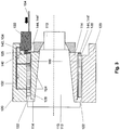
- FIG. 3 shows a longitudinal section through a chock 120 with stored therein roll neck 112 of a support roller 110 with a first variant of the transmission according to the invention between the high pressure pump and the roll neck.
- the high-pressure pump 130 is installed in a recess 125 of the chock 120 such that its drive shaft 134 is preferably aligned parallel to the longitudinal axis of the support roller 110.
- the outwardly projecting free end of the drive shaft 134 is preferably in turn formed as a gear or it is a pinion 142 rotatably mounted on this drive shaft.
- pinion 142 and the drive shaft side gear is in direct engagement with an externally toothed ring gear 144 'of a drive wheel 144, which is mounted coaxially on the balefernen side on the roll neck or a mounted on the roll neck pin bushing 114 rotatably.
- the gear 140 is therefore in the present case of the pinion 142 and the drive wheel 144 with externally toothed ring gear 144 ', which are directly in engagement.
- the transmission 140 could also provide an indirect coupling of pinion and drive wheel, for. B. via a chain or intermediate other gears.
- the installation of the high-pressure pump 130 shown in the niche 125 of the chock 120 represents a very compact design, which is very accommodating the basically always cramped space in the environment of rolling stands.
- the high-pressure pump 130 is connected on the input side to the low-pressure line 154.
- the high-pressure pump 130 pumps the coolant and / or lubricant via high-pressure lines 132 to the high-pressure inlets 124 in the annular gap between the bearing bush 128 and the pin bush 114.
- the high-pressure lines 132 are formed in the interior of the chock 120.
- FIG. 4 essentially corresponds FIG. 1 with the only difference that the high-pressure pump is positioned differently, namely on the front side of the roll neck 112 of the support roller 110, as described below FIG. 6 is described in detail.
- FIG. 5 essentially corresponds to the FIG. 2 with the only difference that here the high pressure pump 130 is also positioned differently, namely at the end face of the roll neck; see also the following description of the FIG. 6 ,
- FIG. 6 shows a longitudinal section through the chock 120 with the roll pin 112 mounted therein the support roller 110.
- the high pressure pump 130 as in the FIGS. 4 and 5 shown disposed on the bale distal end face of the roll neck 112.
- the pinion 142 on the drive shaft 134 of the high-pressure pump is here via the drive wheel 144 with internally toothed ring gear 144 "rotatably coupled directly to the roll neck 112.
- the drive wheel is preferably mounted concentrically on the end face of the roll neck 112 rotatably.
Landscapes
- Engineering & Computer Science (AREA)
- Mechanical Engineering (AREA)
- Rolling Contact Bearings (AREA)
- General Engineering & Computer Science (AREA)
- Reduction Rolling/Reduction Stand/Operation Of Reduction Machine (AREA)
- Metal Rolling (AREA)
- Crushing And Grinding (AREA)
Description
- Die Erfindung betrifft ein Walzgerüst zum Walzen von vorzugsweise metallischem Walzgut.
- Derartige Walzgerüste sind im Stand der Technik grundsätzlich bekannt, z. B. aus der
WO 2013/048836 A1 . Das dort offenbarte Walzgerüst zum Walzen von metallischem Walzgut offenbart eine Walze mit zwei Walzenzapfen, die jeweils in einem Einbaustück, auch Lagergehäuse genannt, drehbar gelagert sind. Hier erfolgt die Lagerung der Walzenzapfen in hoch belasteten Gerüsten in jeweils einem zylinderförmigen Aufnahmeraum in dem Einbaustück, wobei der Aufnahmeraum der Einbaustücke im Bereich maximaler Last mindestens einen Hochdruckzulauf, typischerweise auch mit hydrostatischen Taschen, für Kühl- und/oder Schmiermittel in den Aufnahmeraum aufweist. Darüber hinaus weist das bekannte Walzgerüst eine einlaufseitig an einen Niederdruckkreislauf für das Kühl- und/oder Schmiermittel angeschlossene Hochdruckpumpe auf. Diese ist oben auf dem Walzgerüst montiert und bedient von dort aus über Hochdruckleitungen den Hochdruckzulauf der Einbaustücke mit unter hohem Druck stehenden Kühl- und/oder Schmiermittel. Der Hochdruckzulauf ist an der Wandung des Aufnahmeraumes bzw. in der Wandung einer Lagerbuchse des Einbaustücks im Bereich maximaler Belastung angeordnet. - Der besagte Niederdruckkreislauf für das Kühl- und/oder Schmiermittel umfasst eine Niederdruckpumpe und einen Tank für das Kühl- oder Schmiermittel, welche beide typischerweise unterhalb des Walzgerüstes angeordnet sind. Niederdruckleitungen, welche typischerweise an den Ständerfenstern des Walzgerüstes entlanggeführt sind, verbinden die Niederdruckpumpe mit den Niederdruckzuläufen in dem Aufnahmeraum des Einbaustücks für den Walzenzapfen, wobei diese Niederdruckzuläufe typischerweise auch auf 90° und 270° Positionen am Umfang des Aufnahmeraumes verteilt angeordnet sind. Die Versorgung des Aufnahmeraums bzw. des Ringspaltes zwischen dem Einbaustück und dem darin gelagerten Walzenzapfen mit Kühl- und/oder Schmiermittel unter Niederdruck, d. h. beispielsweise 2 bar, ist in der Regel ausreichend für eine Schmierung des Walzenzapfens bei geringer Walzkraft.
- Bei großer Walzkraft, wie sie insbesondere in den ersten Gerüsten einer Walzstraße auftreten, ist der Niederdruck jedoch in der Regel nicht ausreichend, um eine Separation, d. h. ein Abheben des Walzenzapfens von dem Einbaustück bzw. der Lagerbuchse im Walzbetrieb zu realisieren; dies hat zur Folge, dass der drehende Walzenzapfen das Einbaustück bzw. die Lagerbuchse kontaktiert und bei (seiner) Drehung an der Innenseite des Aufnahmeraumes entlangreibt. Die Folge ist ein unerwünschter Verschleiß von sowohl der Lagerbuchse wie auch des Zapfens bzw. der Zapfenbuchse. Um dies zu verhindern, sieht der Stand der Technik die besagte Hochdruckpumpe vor, welche eingangsseitig über die Niederdruckleitungen mit demselben Kühl- und/oder Schmiermittel versorgt wird, wie es in dem Niederdruckkreislauf verwendet wird. Die Hochdruckpumpe setzt dieses zugeführte Kühl- und/oder Schmiermittel ausgangsseitig unter hohen Druck, typischerweise größer 1.000 bar, vorzugsweise ca. 1.500 bar. Von der Hochdruckpumpe aus wird das Kühl- und/oder Schmiermittel über Hochdruckleitungen und den besagten Hochdruckzulauf im Bereich maximaler Last in den Aufnahmeraum, genauer gesagt, in den Ringspalt zwischen Walzenzapfen und Einbaustück gepresst. Mit dem hohen Druck gelingt es, den Walzenzapfen und damit auch die Walze auch bei hohen Walzkräften von dem Einbaustück zu separieren und den Walzenzapfen auf einem Film, gebildet aus dem Kühl- und/oder Schmiermittel auch unter hoher Last quasi reibungsfrei gleiten zu lassen.
- Die aus der besagten internationalen Patentanmeldung
WO 2013/048836 A1 bekannte Anordnung der Hochdruckpumpe auf dem Walzgerüst ist jedoch aus verschiedenen Gründen nicht sinnvoll:
Zum einen sind die notwendigen Hochdruckleitungen zur Verbindung der oben auf dem Walzgerüst positionierten Hochdruckpumpe ausgangsseitig mit den Hochdruckzuläufen im Einbaustück noch relativ lang. Weiterhin ist ein externer Antrieb für die Hochdruckpumpe erforderlich, der auch oben auf dem Walzgerüst platziert werden müsste. Elektrische oder hydraulische Versorgungsleitungen für diesen Antrieb müssen oben auf das Walzgerüst geführt sein/werden. - Der Erfindung liegt die Aufgabe zugrunde, ein bekanntes Walzgerüst zum Walzen von Walzgut dahingehend weiterzubilden, dass die Kosten für den Antrieb der Hochdruckpumpe verringert werden können.
- Diese Aufgabe wird durch den Gegenstand des Patentanspruchs 1 gelöst. Dieser ist dadurch gekennzeichnet, dass ein Getriebe vorgesehen ist, welches an der ballenfernen Seite des Einbaustücks angeordnet ist zum Drehkoppeln der Hochdruckpumpe mit dem in dem Aufnahmeraum drehbar gelagerten Walzenzapfen.
- Das beanspruchte Getriebe bietet den Vorteil, dass die Hochdruckpumpe durch den Walzenzapfen angetrieben wird, wenn dieser sich dreht. Damit ist ein separater Antrieb, typischerweise ein Elektromotor für die Hochdruckpumpe entbehrlich; dessen Kosten sowie die Kosten für elektronische oder hydraulische Versorgungsleitungen für den Antrieb können eingespart werden.
- Gemäß einem ersten Ausführungsbeispiel ist das Getriebe als Zahnradgetriebe ausgebildet, mit einem Ritzel und einem Treibrad, welche direkt oder indirekt miteinander drehgekoppelt sind. Das Ritzel ist drehfest auf die Antriebswelle der Hochdruckpumpe aufgesetzt oder das freie Ende der Antriebswelle ist selbst als Ritzel ausgebildet. Gemäß einer ersten Variante des Getriebes ist das Treibrad als außenverzahnter Zahnkranzring ausgebildet, welcher vorzugsweise an der ballenfernen Seite drehfest mit dem Walzenzapfen oder mit einer auf den Walzenzapfen drehfest aufgesetzten Zapfenbuchse verbunden ist. Die Hochdruckpumpe ist dann so angeordnet, dass das Ritzel ihrer Antriebswelle mit dem außenverzahnten Zahnkranzring vorzugsweise direkt, d. h. ohne Zwischenschaltung weiterer Zahnräder in Eingriff steht. Wenn eine bestimmte Übersetzung erforderlich ist, können selbstverständlich noch weitere Zahnräder zwischengeschaltet sein. Insbesondere bei der besagten ersten Variante des Getriebes kann die Hochdruckpumpe vorteilhafterweise platzsparend in eine Nische des Einbaustücks eingebaut sein.
- Eine zweite Variante des Getriebes sieht vor, dass das Treibrad als innenverzahnter Zahnkranzring ausgebildet ist, welcher an der ballenfernen Stirnseite des Walzenzapfens drehfest und vorzugsweise koaxial mit diesem verbunden ist. Die Hochdruckpumpe ist dann an der Stirnseite des Walzenzapfens in axialer Richtung derart vorgelagert angeordnet, dass das Ritzel der Antriebswelle der Hochdruckpumpe mit dem innenverzahnten Zahnkranzring vorzugsweise direkt in Eingriff steht.
- Der Ausdruck, dass das Ritzel direkt mit dem Treibrad in Eingriff steht, bedeutet, dass die Zähne des Ritzels in die Verzahnung des Treibrades eingreifen. Demgegenüber bedeutet ein indirektes in Eingriff stehen, dass das Ritzel und das Treibrad über eine Kette oder unter Zwischenschaltung weiterer Zahnräder oder auf sonstige Weise miteinander drehgekoppelt sind.
- Neben dem Hochdruckzulauf ist in dem Aufnahmeraum des Einbaustücks auch mindestens ein Niederdruckzulauf vorgesehen, wobei der Niederdruckzulauf von einem Niederdruckkreislauf für das Kühl- und/oder Schmiermittel versorgt wird. Der Niederdruckkreislauf weist eine Niederdruckpumpe und mindestens eine Niederdruckleitung mit einer Verzweigung auf, um sowohl die Niederdruckzuläufe wie auch die Niederdruck-Eingangsseite der Hochdruckpumpe mit Kühl- und/oder Schmiermittel zu versorgen.
- Die Abzweigung der Niederdruckleitung für den Niederdruckzulauf und die Hochdruckpumpe kann außerhalb des Einbaustücks angeordnet sein, dann vorzugsweise auf Höhe des Einbaustücks, unmittelbar an der an dem Ständer des Walzgerüstes entlanglaufenden Niederdruckleitung. In diesem Fall gehen zwei Niederdruckleitungen von der Verzweigung ab in das Einbaustück.
- Alternativ kann die Verzweigung im Inneren des Einbaustücks realisiert sein. In diesem Fall führt lediglich eine einzige Niederdruckleitung von dem Niederdruckkreislauf in das Einbaustück hinein. Innerhalb des Einbaustücks verzweigt sich dann diese Leitung zu dem Niederdruckzulauf und dem Hochdruckzulauf. Diese zweite Variante für die Verzweigung bietet den Vorteil, dass, wie gesagt, lediglich eine Niederdruckleitung in das Einbaustück hineingeht und damit bei einem Walzenwechsel auch nur diese eine Leitung aufgetrennt bzw. angeschlossen werden muss. Die Gefahr, dass eine Leitung nach einem Walzenwechsel nicht wieder angekuppelt wird, wird dadurch verringert.
- Wenn in dem Einbaustück eine Lagerbuchse als Verschleißteil vorgesehen ist zum Aufspannen des Aufnahmeraumes, dann sind sowohl die Niederdruck- wie auch die Hochdruckzuläufe für das Kühl- und/oder Schmiermittel in der Lagerbuchse ausgebildet. Diese Zuläufe stehen dann mit den entsprechenden Kanälen in dem Einbaustück in fluidleitender Verbindung.
- Der Beschreibung sind sechs Figuren beigefügt, wobei
- Figur 1
- ein Walzgerüst gemäß der Erfindung mit einer ersten Variante für den Anschluss der Hochdruckpumpe an die Niederdruckleitung und mit der Hochdruckpumpe an einer ersten Einbauposition;
- Figur 2
- ein Walzgerüst gemäß der Erfindung gemäß einer zweiten Variante für den Anschluss der Hochdruckpumpe an die Niederdruckleitung und mit der Hochdruckpumpe an der ersten Einbauposition;
- Figur 3
- einen Längsschnitt durch ein Einbaustück mit darin gelagertem Walzenzapfen mit einer ersten Variante des Getriebes zum Antreiben der Hochdruckpumpe an der ersten Einbauposition;
- Figur 4
- ein Walzgerüst gemäß der Erfindung mit der ersten Variante für den Anschluss der Hochdruckpumpe an die Niederdruckleitung und mit der Hochdruckpumpe an einer zweiten Einbauposition;
- Figur 5
- ein Walzgerüst gemäß der Erfindung gemäß der zweiten Variante für den Anschluss der Hochdruckpumpe an die Niederdruckleitung und mit der Hochdruckpumpe an der zweiten Einbauposition; und
- Figur 6
- ein Längsschnitt durch das Einbaustück mit darin gelagertem Walzenzapfen mit der zweiten Variante des Getriebes zum Antreiben der Hochdruckpumpe an der zweiten Einbauposition
- Die Erfindung wird nachfolgend unter Bezugnahme auf die genannten Figuren in Form von Ausführungsbeispielen bzw. Varianten detailliert beschrieben. In allen Figuren sind gleiche technische Merkmale mit gleichen Bezugszeichen bezeichnet.
-
Figur 1 zeigt in schematisierter Form ein Walzgerüst gemäß der Erfindung in Quarto-Bauweise, d. h. mit vier übereinander angeordneten Walzen. Bei den beiden mittleren Walzen handelt es sich um Arbeitswalzen 170, welche typischerweise einen Walzspalt aufspannen, zwischen dem Walzgut in Walzrichtung R hindurch befördert und gewalzt wird. Die beiden Arbeitswalzen 170 werden abgestützt durch eine obere und eine untere Stützwalze 110. Die Stützwalzen sind mit ihren Walzenzapfen 112 in Einbaustücken 120 drehbar gelagert. Die Einbaustücke 120, auch Lagergehäuse genannt, weisen einen zylinderförmigen, eventuell auch konischen Aufnahmeraum 122 auf, in dem die jeweiligen Walzenzapfen 112 der Stützwalzen 110 drehbar gelagert sind. Optional kann der Aufnahmeraum 122 von einer Lagerbuchse 128 aufgespannt werden, welche in dem Einbaustück drehfest angeordnet ist. Zwischen dem Einbaustück 120 bzw. der Lagerbuchse 128 und dem Walzenzapfen 112 bzw. einer optional auf den Walzenzapfen aufgesetzten Zapfenbuchse ist ein Ringspalt ausgebildet, der im Betrieb des Walzgerüstes mit Kühl- und/oder Schmiermittel befüllt ist. Zur Versorgung des Ringspaltes mit dem Kühl- und/oder Schmiermittel sind an der Peripherie des Aufnahmeraumes 122 Zu- und Abläufe für das Kühl- und/oder Schmiermittel vorgesehen. Konkret ist im Bereich maximaler Last mindestens ein Hochdruckzulauf 124 angeordnet, über welchen das Kühl- und/oder Schmiermittel mit Hilfe einer Hochdruckpumpe 130 erforderlichenfalls unter hohem Druck, typischerweise größer 1.000 bar, vorzugsweise 1.500 bar in den Ringspalt hinein gepresst wird. Neben dem Hochdruckzulauf 124 gibt es mindestens einen Niederdruckzulauf 126, welcher typischerweise im Bereich einer 90°- bzw. 270°-Position angeordnet ist. - Um sowohl den besagten Niederdruckzulauf 126, wie auch die Eingangsseite der Hochdruckpumpe 130 mit dem Kühl- und/oder Schmiermittel zu versorgen, ist dem Walzgerüst 100 ein Niederdruckkreislauf 150 zugeordnet. Der Niederdruckkreislauf umfasst eine Niederdruckpumpe 152 zum Bereitstellen des Kühl- und/oder Schmiermittels mit niedrigem Druck, beispielsweise 1 bis 10 bar, vorzugsweise 2 bar. Die Niederdruckpumpe 152 pumpt das Kühl- und/oder Schmiermittel aus einem Tank, welcher sich typischerweise unterhalb des Walzgerüstes befindet, in eine Niederdruckleitung 154. Gemäß einer ersten Variante, wie sie in
Figur 1 dargestellt ist, weist die Niederdruckleitung 154 auf Höhe jedes der Einbaustücke 120 außerhalb der Einbaustücke 120 eine Verzweigung auf, so dass von der Niederdruckleitung 154 zwei separate Niederdruckleitungen 154 in die jeweiligen Einbaustücke 120 geführt sind, um dort zum einen die Eingangsseite der Hochdruckpumpe 130 wie auch den Niederdruckzulauf 126 mit dem - unter niedrigem Druck stehenden - Kühl- und/oder Schmiermittel zu versorgen. - Ein Druckregler 158 sorgt für den notwendigen Vordruck in der Niederdruckleitung 154, die an den Einbaustücken angeschlossen sind.
- Neben den Zuläufen 124, 126 sind in den Einbaustücken 120 auch Abläufe 127 zu erkennen, welche ihrerseits mit den in den Tank zurücklaufenden Niederdruckleitungen 154 leitungsverbunden sind.
- In
Figur 1 ist zu erkennen, dass die Hochdruckpumpe 130 in bzw. zumindest im Bereich des Einbaustücks 120 angeordnet ist. Dies gilt sowohl für das Einbaustück der oberen Stützwalze wie auch für das Einbaustück der unteren Stützwalze. Erfindungsgemäß wird die Hochdruckpumpe 130 von dem Walzenzapfen 112 der Stützwalze 110 mit angetrieben, wenn dieser sich dreht. Details zu diesem erfindungsgemäßen Drehantrieb sind weiter unten unter Bezugnahme aufFigur 3 beschrieben. -
Figur 2 zeigt im Wesentlichen dasselbe Walzgerüst 100, wie soeben unter Bezugnahme aufFigur 1 beschrieben. Der einzige Unterscheid besteht darin, dassFigur 2 eine zweite Variante für den Anschluss des Einbaustücks 120 und insbesondere der Hochdruckpumpe 130 an die Niederdruckleitung 154 aufzeigt. Konkret sieht diese zweite Variante vor, dass nicht zwei Niederdruckleitungen 154, sondern lediglich eine einzige Niederdruckleitung 154 in das Einbaustück 120 hineingeführt ist und dass sich innerhalb des Einbaustücks eine Verzweigung 156 befindet, von der aus eine Niederdruckleitung für das Kühl- und/oder Schmiermittel an den Niederdruckzulauf 126 und die Eingangsseite der Hochdruckpumpe 130 abzweigt. Das Vorsehen von lediglich einem Niederdruckzugang pro Einbaustück 120 spart nicht nur die Mehrkosten für die einmalige Montage der zweiten Niederdruckleitung, sondern auch die Folgekosten, welche entstehen, wenn bei jedem Wechsel der Stützwalzen nicht nur eine, sondern zwei Niederdruckleitungen von dem Einbaustück abgetrennt und bei Einbau der neuen Walzen wieder angeschlossen werden müssen. -
Figur 3 zeigt einen Längsschnitt durch ein Einbaustück 120 mit darin gelagertem Walzenzapfen 112 einer Stützwalze 110 mit einer ersten Variante des erfindungsgemäßen Getriebes zwischen der Hochdruckpumpe und dem Walzenzapfen. Konkret ist zu erkennen, dass die Hochdruckpumpe 130 in einer Nische 125 des Einbaustücks 120 derart eingebaut ist, dass ihre Antriebswelle 134 vorzugsweise parallel zur Längsachse der Stützwalze 110 ausgerichtet ist. Das nach außen vorstehende freie Ende der Antriebswelle 134 ist vorzugsweise seinerseits als Zahnrad ausgebildet oder es ist ein Ritzel 142 drehfest auf diese Antriebswelle montiert. Bei der inFigur 3 gezeigten ersten Variante des Getriebes steht das Ritzel 142 bzw. das antriebswellenseitige Zahnrad in direktem Eingriff mit einem außenverzahnten Zahnkranzring 144' eines Treibrades 144, welches koaxial an der ballenfernen Seite auf dem Walzenzapfen oder einer auf den Walzenzapfen aufgesetzten Zapfenbuchse 114 drehfest montiert ist. Das Getriebe 140 besteht deshalb im vorliegenden Fall aus dem Ritzel 142 und dem Treibrad 144 mit außenverzahntem Zahnkranzring 144', welche direkt miteinander in Eingriff stehen. Alternativ könnte das Getriebe 140 auch eine indirekte Kopplung von Ritzel und Treibrad vorsehen, z. B. über eine Kette oder zwischengeschaltete weitere Getrieberäder. Der gezeigte Einbau der Hochdruckpumpe 130 in die Nische 125 des Einbaustücks 120 stellt eine sehr kompakte Bauweise dar, was den grundsätzlich immer recht beengten Raumverhältnissen im Umfeld von Walzgerüsten sehr entgegenkommt. - In
Figur 3 ist zu erkennen, dass die Hochdruckpumpe 130 eingangsseitig an die Niederdruckleitung 154 angeschlossen ist. Ausgangsseitig pumpt die Hochdruckpumpe 130 das Kühl- und/oder Schmiermittel über Hochdruckleitungen 132 an die Hochdruckzuläufe 124 in dem Ringspalt zwischen der Lagerbuchse 128 und der Zapfenbuchse 114. Die Hochdruckleitungen 132 sind im Inneren des Einbaustücks 120 ausgebildet. -
Figur 4 entspricht im WesentlichenFigur 1 mit dem einzigen Unterschied, dass die Hochdruckpumpe anders positioniert ist, nämlich an der Stirnseite des Walzenzapfens 112 der Stützwalze 110, wie dies weiter unten inFigur 6 detailliert beschrieben ist. -
Figur 5 entspricht im Wesentlichen derFigur 2 mit dem einzigen Unterschied, dass hier die Hochdruckpumpe 130 ebenfalls anders positioniert ist, nämlich an der Stirnseite des Walzenzapfens; siehe auch hierzu die nachfolgende Beschreibung derFigur 6 . -
Figur 6 zeigt einen Längsschnitt durch das Einbaustück 120 mit dem darin gelagerten Walzenzapfen 112 der Stützwalze 110. Im Unterschied zuFigur 3 ist hier die Hochdruckpumpe 130, wie in denFiguren 4 und 5 gezeigt, an der ballenfernen Stirnseite des Walzenzapfens 112 angeordnet. Das Ritzel 142 auf der Antriebswelle 134 der Hochdruckpumpe ist hier über das Treibrad 144 mit innenverzahntem Zahnkranzring 144" direkt mit dem Walzenzapfen 112 drehgekoppelt. Das Treibrad ist vorzugsweise konzentrisch auf der Stirnseite des Walzenzapfens 112 drehfest montiert. -
- 100
- Walzgerüst
- 110
- Stützwalze
- 112
- Walzenzapfen der Stützwalze
- 113
- Walzenzapfenende
- 114
- Zapfenbuchse
- 116
- ballenferne Stirnseite des Walzenzapfens
- 120
- Einbaustück
- 122
- Aufnahmeraum
- 124
- Hochdruckzulauf
- 125
- Nische im Einbaustück
- 126
- Niederdruckzulauf
- 127
- Ablauf
- 128
- Lagerbuchse
- 130
- Hochdruckpumpe
- 132
- Hochdruckleitung
- 134
- Antriebswelle der Hochdruckpumpe
- 140
- Getriebe
- 142
- Ritzel
- 144
- Treibrad
- 144'
- außenverzahnter Zahnkranzring
- 144"
- innenverzahnter Zahnkranzring
- 150
- Niederdruckkreislauf
- 152
- Niederdruckpumpe
- 154
- Niederdruckleitung
- 156
- Verzweigung
- 158
- Druckregler
- 160
- Ringspalt
- 170
- Arbeitswalzen
- T
- Niederdruckrückleitung vom Walzgerüst in den Tank
- P
- Niederdruckhinleitung vom Tank zum Walzgerüst
- R
- Walzrichtung
Claims (10)
- Walzgerüst (100) zum Walzen von vorzugsweise metallischem Walzgut; aufweisend:eine Walze (110) mit zwei Walzenzapfen (112);zwei Einbaustücke (120) mit jeweils einem zylinderförmigen Aufnahmeraum (122) zur drehbaren Lagerung eines der Walzenzapfen (112) der Walze (110),wobei der Aufnahmeraum in mindestens einem der Einbaustücke (120) im Bereich maximaler Last mindestens einen Hochdruckzulauf (124) für Kühl- und/oder Schmiermittel aufweist;mindestens eine dem mindestens einen Einbaustück (120) zugeordnete Hochdruckpumpe (130), undHochdruckleitungen (132) zum Verbinden der Ausgangsseite der Hochdruckpumpe (130) mit dem Hochdruckzulauf (124) zum Zuführen des Kühl- und/oder Schmiermittels in den Aufnahmeraum (122);gekennzeichnet durchein Getriebe (140), welches an der ballenfernen Seite des Einbaustücks (120) angeordnet ist, zum Drehkoppeln der Hochdruckpumpe (130) mit dem in dem Aufnahmeraum (122) drehbar gelagerten Walzenzapfen (112).
- Walzgerüst (100) nach Anspruch 1,
dadurch gekennzeichnet, dass
das Getriebe (140) als Zahnradgetriebe ausgebildet ist mit einem Ritzel (142) und einem Treibrad (144), welche direkt oder indirekt miteinander drehgekoppelt sind; und
das Ritzel (142) drehfest auf die Antriebswelle (134) der Hochdruckpumpe (130) aufgesetzt ist oder das freie Ende der Antriebswelle (134) als das Ritzel ausgebildet ist. - Walzgerüst (100) nach Anspruch 2,
dadurch gekennzeichnet, dass
das Treibrad (144) als außenverzahnter Zahnkranzring ausgebildet ist, welcher vorzugsweise an der ballenfernen Seite drehfest mit dem Walzenzapfen (112) oder mit einer auf den Walzenzapfen drehfest aufgesetzten Zapfenbuchse (114) verbunden ist; und
die Hochdruckpumpe (130) so angeordnet ist, dass das Ritzel ihrer Antriebswelle (134) mit dem außenverzahnten Zahnkranzring, vorzugsweise direkt, in Eingriff steht. - Walzgerüst (100) nach Anspruch 2,
dadurch gekennzeichnet, dass
das Treibrad (144) als innenverzahnter Zahnkranzring ausgebildet ist, welcher an der ballenfernen Stirnseite (116) des Walzenzapfens (112) drehfest mit dem Walzenzapfen verbunden ist, wobei die Hochdruckpumpe (130) an der Stirnseite des Walzenzapfens derart vorgelagert angeordnet ist, dass das Ritzel (142) ihrer Antriebswelle (134) mit dem innenverzahnten Zahnkranzring, vorzugsweise direkt, in Eingriff steht. - Walzgerüst (100) nach einem der vorangegangenen Ansprüche,
dadurch gekennzeichnet, dass
die Hochdruckpumpe (130) in das Einbaustück (120) integriert, beispielsweise in eine Nische (125) des Einbaustücks eingebaut, ist. - Walzgerüst (100) nach einem der vorangegangenen Ansprüche,
dadurch gekennzeichnet, dass
das Einbaustück (120) neben dem Hochdruckzulauf (124) auch mindestens einen Niederdruckzulauf (126) für das Kühl- und/oder Schmiermittel in den Aufnahmeraum (122) aufweist; und
ein Niederdruckkreislauf (150) vorhanden ist, welcher eine Niederdruckpumpe (152) und mindestens eine Niederdruckleitung (154) mit einer Verzweigung (156) aufweist zum Bereitstellen des Kühl- und/oder Schmiermittels mit niedrigem Druck, beispielsweise 1-10 bar, sowohl für den Niederdruckzulauf (126) wie auch für die Eingangsseite der Hochdruckpumpe (130). - Walzgerüst (100) nach Anspruch 6,
dadurch gekennzeichnet, dass
die Verzweigung (156) außerhalb des Einbaustücks (120), vorzugsweise auf Höhe des Einbaustücks, an der am Ständer des Walzgerüstes entlanglaufenden Niederdruckleitung (154) vorgesehen ist. - Walzgerüst (100) nach Anspruch 6,
dadurch gekennzeichnet, dass
lediglich eine einzige Niederdruckleitung (154) in das Einbaustück (120) hineingeführt ist; und
die Verzweigung (156) zu dem Niederdruckzulauf (126) und zu dem Hochdruckzulauf (124) innerhalb des Einbaustücks (120) ausgebildet ist. - Walzgerüst (100) nach einem der vorangegangenen Ansprüche,
dadurch gekennzeichnet, dass
das mindestens ein Einbaustück (120) eine drehfest angeordnete Lagerbuchse (128) aufweist, welche den Aufnahmeraum (122) aufspannt, wobei der mindestens eine Niederdruck- und Hochdruckzulauf (124, 126) für das Kühl- und/Schmiermittel in den Aufnahmeraum in der Lagerbuchse (128) ausgebildet ist. - Walzgerüst nach einem der vorangegangenen Ansprüche,
dadurch gekennzeichnet, dass
jedem Hochdruckzulauf des Einbaustücks eine einzige Hochdruckpumpe individuell zugeordnet ist.
Applications Claiming Priority (3)
| Application Number | Priority Date | Filing Date | Title |
|---|---|---|---|
| DE102015214642 | 2015-07-31 | ||
| DE102015223690.0A DE102015223690A1 (de) | 2015-07-31 | 2015-11-30 | Walzgerüst zum Walzen von Walzgut |
| PCT/EP2016/067898 WO2017021250A1 (de) | 2015-07-31 | 2016-07-27 | Walzgerüst zum walzen von walzgut |
Publications (2)
| Publication Number | Publication Date |
|---|---|
| EP3328563A1 EP3328563A1 (de) | 2018-06-06 |
| EP3328563B1 true EP3328563B1 (de) | 2018-12-12 |
Family
ID=57795527
Family Applications (1)
| Application Number | Title | Priority Date | Filing Date |
|---|---|---|---|
| EP16744396.9A Not-in-force EP3328563B1 (de) | 2015-07-31 | 2016-07-27 | Walzgerüst zum walzen von walzgut |
Country Status (5)
| Country | Link |
|---|---|
| US (1) | US10974297B2 (de) |
| EP (1) | EP3328563B1 (de) |
| CN (1) | CN107847997B (de) |
| DE (1) | DE102015223690A1 (de) |
| WO (1) | WO2017021250A1 (de) |
Families Citing this family (2)
| Publication number | Priority date | Publication date | Assignee | Title |
|---|---|---|---|---|
| CN111299328B (zh) * | 2020-03-16 | 2022-03-22 | 常州市一马机械有限公司 | 新型环保轧机底座、轧管机及其工作方法 |
| JP7276281B2 (ja) * | 2020-08-24 | 2023-05-18 | Jfeスチール株式会社 | 油膜軸受構造、熱間圧延機、温間圧延機、及び冷間圧延機 |
Family Cites Families (17)
| Publication number | Priority date | Publication date | Assignee | Title |
|---|---|---|---|---|
| US3076524A (en) * | 1960-02-08 | 1963-02-05 | Eastern Rolling Mills Inc | Bearings |
| US3101980A (en) * | 1960-10-06 | 1963-08-27 | Glacier Co Ltd | Hydrodynamic bearing assembly |
| US3422650A (en) * | 1967-02-23 | 1969-01-21 | Bliss Co | Gauge control for a rolling mill |
| US3453031A (en) * | 1967-04-06 | 1969-07-01 | Morgan Construction Co | Bearing assembly |
| GB1372914A (en) * | 1971-05-06 | 1974-11-06 | Lauener W F Ag | Apparatus for rolling metal strip |
| DE2123557B1 (de) * | 1971-05-12 | 1972-05-31 | G Schwartz & Co | Schmiervorrichtung für Walzspindeln von Walzwerken |
| JP2542245B2 (ja) | 1988-10-21 | 1996-10-09 | 横河電機株式会社 | 電圧出力回路 |
| WO2000000013A1 (fr) | 1998-06-30 | 2000-01-06 | Pascal Peleszezak | Dispositif pour la realisation de massifs et decors floraux |
| US6692689B2 (en) * | 2001-12-14 | 2004-02-17 | Jorge A. Morando | Sink roll assembly with forced hydrodynamic film lubricated bearings and self-aligning holding arms |
| US7461532B2 (en) * | 2005-02-08 | 2008-12-09 | Morgan Construction Company | Monitoring and alarm system for rolling mill oil film bearings |
| CN2800041Y (zh) * | 2005-05-20 | 2006-07-26 | 鞍钢新轧钢股份有限公司 | 轧机主传动电机滑动轴承润滑装置 |
| DE102009012398B4 (de) | 2009-03-13 | 2013-11-28 | Blohm + Voss Industries Gmbh | Radialgleitlager und Verfahren für eine Schmiermittelversorgung |
| CN201676890U (zh) * | 2010-02-22 | 2010-12-22 | 北京昆仑轴承有限公司 | 一种带有双唇单侧密封的轧机轴承 |
| DE102011002833A1 (de) * | 2011-01-18 | 2012-07-19 | Sms Siemag Ag | Walzgerüst für eine Walze, Verfahren zum Betreiben des Walzgerüstes und Verwendung für eine axiale Abstützvorrichtung |
| US9016099B2 (en) | 2011-09-29 | 2015-04-28 | Siemens Industry, Inc. | Hybrid hydrodynamic and hydrostatic bearing bushing and lubrication system for rolling mill |
| DE102012224511A1 (de) * | 2012-12-28 | 2014-07-03 | Sms Siemag Ag | Einbaustück zum Lagern einer Walze in einem Walzenständer |
| CN203488955U (zh) * | 2013-08-27 | 2014-03-19 | 天津市宇润德金属制品有限公司 | 用于轧机支承辊轴承座的润滑油加注循环系统 |
-
2015
- 2015-11-30 DE DE102015223690.0A patent/DE102015223690A1/de not_active Withdrawn
-
2016
- 2016-07-27 CN CN201680044896.0A patent/CN107847997B/zh not_active Expired - Fee Related
- 2016-07-27 US US15/745,481 patent/US10974297B2/en not_active Expired - Fee Related
- 2016-07-27 EP EP16744396.9A patent/EP3328563B1/de not_active Not-in-force
- 2016-07-27 WO PCT/EP2016/067898 patent/WO2017021250A1/de not_active Ceased
Non-Patent Citations (1)
| Title |
|---|
| None * |
Also Published As
| Publication number | Publication date |
|---|---|
| US10974297B2 (en) | 2021-04-13 |
| WO2017021250A1 (de) | 2017-02-09 |
| CN107847997B (zh) | 2019-04-05 |
| EP3328563A1 (de) | 2018-06-06 |
| US20180207696A1 (en) | 2018-07-26 |
| CN107847997A (zh) | 2018-03-27 |
| DE102015223690A1 (de) | 2017-02-02 |
Similar Documents
| Publication | Publication Date | Title |
|---|---|---|
| EP2406497B1 (de) | Hydraulische zahnradmaschine | |
| DE4227037B4 (de) | Hydrostatische Axialkolbenpumpe | |
| EP3371418B1 (de) | Walzenschrämlader | |
| EP3328563B1 (de) | Walzgerüst zum walzen von walzgut | |
| DE1528540B2 (de) | Steuerung für einen hydraulischen Radialkolbenmotor | |
| EP3366917A1 (de) | Getriebe für eine windenergieanlage | |
| EP3302836B1 (de) | Walzenanordnung | |
| EP2598262B1 (de) | Walzgerüst mit walzenlagerung | |
| EP4072737B1 (de) | Reinigungsvorrichtung | |
| DE2618882A1 (de) | Planetengetriebe, insbesondere fuer den antrieb von mehreren walzen o.dgl., mit kleinen achsabstand | |
| DE102015219752A1 (de) | Lagerbuchse | |
| EP3328564B1 (de) | Walzgerüst zum walzen von walzgut | |
| DE102009044725B3 (de) | Walze | |
| EP2441982B1 (de) | Planetentrieb mit einem ersten Satz Planetenräder und mit einem zweiten Satz Planetenräder und eine Baueinheit in einem derartigen Planetentrieb | |
| EP3034187B1 (de) | Walzgerüst mit verschiebeeinrichtung | |
| DE102007043403B3 (de) | Walzgerüst zum Walzen von metallischen Bändern sowie Walze oder Rolle für ein solches Walzgerüst | |
| DE905779C (de) | Aufzugsmaschine | |
| DE1551070C (de) | Parallel- und außenachsige Rotationskolbenmaschine | |
| DE102004033490A1 (de) | Innenzahnradmaschine | |
| DE2113250A1 (de) | Axiallagerung,insbesondere fuer Mehrschneckenpressen | |
| DE102009042255B4 (de) | Walzgerüst mit mindestens 3 Walzen und Walzblock mit einem derartigen Walzgerüst | |
| DE19815480B4 (de) | Angeflanschte Zahnradpumpe für Hydraulikkreislauf in einem Verdichter | |
| WO2013160149A2 (de) | Radialkolbenmaschine | |
| EP3560615A1 (de) | Walzgeruest | |
| DE202005004416U1 (de) | Fluidabgabeeinrichtung für Wellen |
Legal Events
| Date | Code | Title | Description |
|---|---|---|---|
| STAA | Information on the status of an ep patent application or granted ep patent |
Free format text: STATUS: THE INTERNATIONAL PUBLICATION HAS BEEN MADE |
|
| PUAI | Public reference made under article 153(3) epc to a published international application that has entered the european phase |
Free format text: ORIGINAL CODE: 0009012 |
|
| STAA | Information on the status of an ep patent application or granted ep patent |
Free format text: STATUS: REQUEST FOR EXAMINATION WAS MADE |
|
| 17P | Request for examination filed |
Effective date: 20180228 |
|
| AK | Designated contracting states |
Kind code of ref document: A1 Designated state(s): AL AT BE BG CH CY CZ DE DK EE ES FI FR GB GR HR HU IE IS IT LI LT LU LV MC MK MT NL NO PL PT RO RS SE SI SK SM TR |
|
| AX | Request for extension of the european patent |
Extension state: BA ME |
|
| GRAP | Despatch of communication of intention to grant a patent |
Free format text: ORIGINAL CODE: EPIDOSNIGR1 |
|
| STAA | Information on the status of an ep patent application or granted ep patent |
Free format text: STATUS: GRANT OF PATENT IS INTENDED |
|
| DAV | Request for validation of the european patent (deleted) | ||
| DAX | Request for extension of the european patent (deleted) | ||
| INTG | Intention to grant announced |
Effective date: 20180718 |
|
| GRAS | Grant fee paid |
Free format text: ORIGINAL CODE: EPIDOSNIGR3 |
|
| GRAA | (expected) grant |
Free format text: ORIGINAL CODE: 0009210 |
|
| STAA | Information on the status of an ep patent application or granted ep patent |
Free format text: STATUS: THE PATENT HAS BEEN GRANTED |
|
| AK | Designated contracting states |
Kind code of ref document: B1 Designated state(s): AL AT BE BG CH CY CZ DE DK EE ES FI FR GB GR HR HU IE IS IT LI LT LU LV MC MK MT NL NO PL PT RO RS SE SI SK SM TR |
|
| REG | Reference to a national code |
Ref country code: GB Ref legal event code: FG4D Free format text: NOT ENGLISH |
|
| REG | Reference to a national code |
Ref country code: CH Ref legal event code: EP |
|
| REG | Reference to a national code |
Ref country code: AT Ref legal event code: REF Ref document number: 1075269 Country of ref document: AT Kind code of ref document: T Effective date: 20181215 |
|
| REG | Reference to a national code |
Ref country code: DE Ref legal event code: R096 Ref document number: 502016002862 Country of ref document: DE |
|
| REG | Reference to a national code |
Ref country code: IE Ref legal event code: FG4D Free format text: LANGUAGE OF EP DOCUMENT: GERMAN |
|
| REG | Reference to a national code |
Ref country code: NL Ref legal event code: MP Effective date: 20181212 |
|
| REG | Reference to a national code |
Ref country code: LT Ref legal event code: MG4D |
|
| PG25 | Lapsed in a contracting state [announced via postgrant information from national office to epo] |
Ref country code: HR Free format text: LAPSE BECAUSE OF FAILURE TO SUBMIT A TRANSLATION OF THE DESCRIPTION OR TO PAY THE FEE WITHIN THE PRESCRIBED TIME-LIMIT Effective date: 20181212 Ref country code: NO Free format text: LAPSE BECAUSE OF FAILURE TO SUBMIT A TRANSLATION OF THE DESCRIPTION OR TO PAY THE FEE WITHIN THE PRESCRIBED TIME-LIMIT Effective date: 20190312 Ref country code: BG Free format text: LAPSE BECAUSE OF FAILURE TO SUBMIT A TRANSLATION OF THE DESCRIPTION OR TO PAY THE FEE WITHIN THE PRESCRIBED TIME-LIMIT Effective date: 20190312 Ref country code: LV Free format text: LAPSE BECAUSE OF FAILURE TO SUBMIT A TRANSLATION OF THE DESCRIPTION OR TO PAY THE FEE WITHIN THE PRESCRIBED TIME-LIMIT Effective date: 20181212 Ref country code: FI Free format text: LAPSE BECAUSE OF FAILURE TO SUBMIT A TRANSLATION OF THE DESCRIPTION OR TO PAY THE FEE WITHIN THE PRESCRIBED TIME-LIMIT Effective date: 20181212 Ref country code: ES Free format text: LAPSE BECAUSE OF FAILURE TO SUBMIT A TRANSLATION OF THE DESCRIPTION OR TO PAY THE FEE WITHIN THE PRESCRIBED TIME-LIMIT Effective date: 20181212 Ref country code: LT Free format text: LAPSE BECAUSE OF FAILURE TO SUBMIT A TRANSLATION OF THE DESCRIPTION OR TO PAY THE FEE WITHIN THE PRESCRIBED TIME-LIMIT Effective date: 20181212 |
|
| PG25 | Lapsed in a contracting state [announced via postgrant information from national office to epo] |
Ref country code: GR Free format text: LAPSE BECAUSE OF FAILURE TO SUBMIT A TRANSLATION OF THE DESCRIPTION OR TO PAY THE FEE WITHIN THE PRESCRIBED TIME-LIMIT Effective date: 20190313 Ref country code: SE Free format text: LAPSE BECAUSE OF FAILURE TO SUBMIT A TRANSLATION OF THE DESCRIPTION OR TO PAY THE FEE WITHIN THE PRESCRIBED TIME-LIMIT Effective date: 20181212 Ref country code: RS Free format text: LAPSE BECAUSE OF FAILURE TO SUBMIT A TRANSLATION OF THE DESCRIPTION OR TO PAY THE FEE WITHIN THE PRESCRIBED TIME-LIMIT Effective date: 20181212 Ref country code: AL Free format text: LAPSE BECAUSE OF FAILURE TO SUBMIT A TRANSLATION OF THE DESCRIPTION OR TO PAY THE FEE WITHIN THE PRESCRIBED TIME-LIMIT Effective date: 20181212 |
|
| PG25 | Lapsed in a contracting state [announced via postgrant information from national office to epo] |
Ref country code: NL Free format text: LAPSE BECAUSE OF FAILURE TO SUBMIT A TRANSLATION OF THE DESCRIPTION OR TO PAY THE FEE WITHIN THE PRESCRIBED TIME-LIMIT Effective date: 20181212 |
|
| PG25 | Lapsed in a contracting state [announced via postgrant information from national office to epo] |
Ref country code: PL Free format text: LAPSE BECAUSE OF FAILURE TO SUBMIT A TRANSLATION OF THE DESCRIPTION OR TO PAY THE FEE WITHIN THE PRESCRIBED TIME-LIMIT Effective date: 20181212 Ref country code: CZ Free format text: LAPSE BECAUSE OF FAILURE TO SUBMIT A TRANSLATION OF THE DESCRIPTION OR TO PAY THE FEE WITHIN THE PRESCRIBED TIME-LIMIT Effective date: 20181212 Ref country code: PT Free format text: LAPSE BECAUSE OF FAILURE TO SUBMIT A TRANSLATION OF THE DESCRIPTION OR TO PAY THE FEE WITHIN THE PRESCRIBED TIME-LIMIT Effective date: 20190412 |
|
| PG25 | Lapsed in a contracting state [announced via postgrant information from national office to epo] |
Ref country code: EE Free format text: LAPSE BECAUSE OF FAILURE TO SUBMIT A TRANSLATION OF THE DESCRIPTION OR TO PAY THE FEE WITHIN THE PRESCRIBED TIME-LIMIT Effective date: 20181212 Ref country code: SM Free format text: LAPSE BECAUSE OF FAILURE TO SUBMIT A TRANSLATION OF THE DESCRIPTION OR TO PAY THE FEE WITHIN THE PRESCRIBED TIME-LIMIT Effective date: 20181212 Ref country code: IS Free format text: LAPSE BECAUSE OF FAILURE TO SUBMIT A TRANSLATION OF THE DESCRIPTION OR TO PAY THE FEE WITHIN THE PRESCRIBED TIME-LIMIT Effective date: 20190412 Ref country code: SK Free format text: LAPSE BECAUSE OF FAILURE TO SUBMIT A TRANSLATION OF THE DESCRIPTION OR TO PAY THE FEE WITHIN THE PRESCRIBED TIME-LIMIT Effective date: 20181212 Ref country code: RO Free format text: LAPSE BECAUSE OF FAILURE TO SUBMIT A TRANSLATION OF THE DESCRIPTION OR TO PAY THE FEE WITHIN THE PRESCRIBED TIME-LIMIT Effective date: 20181212 |
|
| REG | Reference to a national code |
Ref country code: DE Ref legal event code: R097 Ref document number: 502016002862 Country of ref document: DE |
|
| PLBE | No opposition filed within time limit |
Free format text: ORIGINAL CODE: 0009261 |
|
| STAA | Information on the status of an ep patent application or granted ep patent |
Free format text: STATUS: NO OPPOSITION FILED WITHIN TIME LIMIT |
|
| PG25 | Lapsed in a contracting state [announced via postgrant information from national office to epo] |
Ref country code: DK Free format text: LAPSE BECAUSE OF FAILURE TO SUBMIT A TRANSLATION OF THE DESCRIPTION OR TO PAY THE FEE WITHIN THE PRESCRIBED TIME-LIMIT Effective date: 20181212 |
|
| 26N | No opposition filed |
Effective date: 20190913 |
|
| PG25 | Lapsed in a contracting state [announced via postgrant information from national office to epo] |
Ref country code: MC Free format text: LAPSE BECAUSE OF FAILURE TO SUBMIT A TRANSLATION OF THE DESCRIPTION OR TO PAY THE FEE WITHIN THE PRESCRIBED TIME-LIMIT Effective date: 20181212 |
|
| REG | Reference to a national code |
Ref country code: CH Ref legal event code: PL |
|
| PG25 | Lapsed in a contracting state [announced via postgrant information from national office to epo] |
Ref country code: TR Free format text: LAPSE BECAUSE OF FAILURE TO SUBMIT A TRANSLATION OF THE DESCRIPTION OR TO PAY THE FEE WITHIN THE PRESCRIBED TIME-LIMIT Effective date: 20181212 |
|
| REG | Reference to a national code |
Ref country code: BE Ref legal event code: MM Effective date: 20190731 |
|
| PG25 | Lapsed in a contracting state [announced via postgrant information from national office to epo] |
Ref country code: LU Free format text: LAPSE BECAUSE OF NON-PAYMENT OF DUE FEES Effective date: 20190727 Ref country code: LI Free format text: LAPSE BECAUSE OF NON-PAYMENT OF DUE FEES Effective date: 20190731 Ref country code: CH Free format text: LAPSE BECAUSE OF NON-PAYMENT OF DUE FEES Effective date: 20190731 Ref country code: BE Free format text: LAPSE BECAUSE OF NON-PAYMENT OF DUE FEES Effective date: 20190731 |
|
| PG25 | Lapsed in a contracting state [announced via postgrant information from national office to epo] |
Ref country code: FR Free format text: LAPSE BECAUSE OF NON-PAYMENT OF DUE FEES Effective date: 20190731 |
|
| PG25 | Lapsed in a contracting state [announced via postgrant information from national office to epo] |
Ref country code: IE Free format text: LAPSE BECAUSE OF NON-PAYMENT OF DUE FEES Effective date: 20190727 |
|
| GBPC | Gb: european patent ceased through non-payment of renewal fee |
Effective date: 20200727 |
|
| PG25 | Lapsed in a contracting state [announced via postgrant information from national office to epo] |
Ref country code: GB Free format text: LAPSE BECAUSE OF NON-PAYMENT OF DUE FEES Effective date: 20200727 |
|
| PG25 | Lapsed in a contracting state [announced via postgrant information from national office to epo] |
Ref country code: CY Free format text: LAPSE BECAUSE OF FAILURE TO SUBMIT A TRANSLATION OF THE DESCRIPTION OR TO PAY THE FEE WITHIN THE PRESCRIBED TIME-LIMIT Effective date: 20181212 |
|
| PG25 | Lapsed in a contracting state [announced via postgrant information from national office to epo] |
Ref country code: HU Free format text: LAPSE BECAUSE OF FAILURE TO SUBMIT A TRANSLATION OF THE DESCRIPTION OR TO PAY THE FEE WITHIN THE PRESCRIBED TIME-LIMIT; INVALID AB INITIO Effective date: 20160727 Ref country code: MT Free format text: LAPSE BECAUSE OF FAILURE TO SUBMIT A TRANSLATION OF THE DESCRIPTION OR TO PAY THE FEE WITHIN THE PRESCRIBED TIME-LIMIT Effective date: 20181212 |
|
| PG25 | Lapsed in a contracting state [announced via postgrant information from national office to epo] |
Ref country code: SI Free format text: LAPSE BECAUSE OF FAILURE TO SUBMIT A TRANSLATION OF THE DESCRIPTION OR TO PAY THE FEE WITHIN THE PRESCRIBED TIME-LIMIT Effective date: 20181212 |
|
| PGFP | Annual fee paid to national office [announced via postgrant information from national office to epo] |
Ref country code: AT Payment date: 20210722 Year of fee payment: 6 Ref country code: IT Payment date: 20210727 Year of fee payment: 6 |
|
| PGFP | Annual fee paid to national office [announced via postgrant information from national office to epo] |
Ref country code: DE Payment date: 20210721 Year of fee payment: 6 |
|
| PG25 | Lapsed in a contracting state [announced via postgrant information from national office to epo] |
Ref country code: MK Free format text: LAPSE BECAUSE OF FAILURE TO SUBMIT A TRANSLATION OF THE DESCRIPTION OR TO PAY THE FEE WITHIN THE PRESCRIBED TIME-LIMIT Effective date: 20181212 |
|
| REG | Reference to a national code |
Ref country code: DE Ref legal event code: R119 Ref document number: 502016002862 Country of ref document: DE |
|
| REG | Reference to a national code |
Ref country code: AT Ref legal event code: MM01 Ref document number: 1075269 Country of ref document: AT Kind code of ref document: T Effective date: 20220727 |
|
| PG25 | Lapsed in a contracting state [announced via postgrant information from national office to epo] |
Ref country code: AT Free format text: LAPSE BECAUSE OF NON-PAYMENT OF DUE FEES Effective date: 20220727 |
|
| PG25 | Lapsed in a contracting state [announced via postgrant information from national office to epo] |
Ref country code: DE Free format text: LAPSE BECAUSE OF NON-PAYMENT OF DUE FEES Effective date: 20230201 |
|
| PG25 | Lapsed in a contracting state [announced via postgrant information from national office to epo] |
Ref country code: IT Free format text: LAPSE BECAUSE OF NON-PAYMENT OF DUE FEES Effective date: 20220727 |