EP3328802B1 - Verfahren und anlage zur halbkontinuierlichen thermischen hydrolyse von schlamm - Google Patents
Verfahren und anlage zur halbkontinuierlichen thermischen hydrolyse von schlamm Download PDFInfo
- Publication number
- EP3328802B1 EP3328802B1 EP16736199.7A EP16736199A EP3328802B1 EP 3328802 B1 EP3328802 B1 EP 3328802B1 EP 16736199 A EP16736199 A EP 16736199A EP 3328802 B1 EP3328802 B1 EP 3328802B1
- Authority
- EP
- European Patent Office
- Prior art keywords
- sludges
- sludge
- steam
- injection
- reaction spaces
- Prior art date
- Legal status (The legal status is an assumption and is not a legal conclusion. Google has not performed a legal analysis and makes no representation as to the accuracy of the status listed.)
- Active
Links
Images



Classifications
-
- C—CHEMISTRY; METALLURGY
- C02—TREATMENT OF WATER, WASTE WATER, SEWAGE, OR SLUDGE
- C02F—TREATMENT OF WATER, WASTE WATER, SEWAGE, OR SLUDGE
- C02F11/00—Treatment of sludge; Devices therefor
- C02F11/18—Treatment of sludge; Devices therefor by thermal conditioning
-
- C—CHEMISTRY; METALLURGY
- C02—TREATMENT OF WATER, WASTE WATER, SEWAGE, OR SLUDGE
- C02F—TREATMENT OF WATER, WASTE WATER, SEWAGE, OR SLUDGE
- C02F2209/00—Controlling or monitoring parameters in water treatment
- C02F2209/02—Temperature
-
- C—CHEMISTRY; METALLURGY
- C02—TREATMENT OF WATER, WASTE WATER, SEWAGE, OR SLUDGE
- C02F—TREATMENT OF WATER, WASTE WATER, SEWAGE, OR SLUDGE
- C02F2209/00—Controlling or monitoring parameters in water treatment
- C02F2209/03—Pressure
-
- C—CHEMISTRY; METALLURGY
- C02—TREATMENT OF WATER, WASTE WATER, SEWAGE, OR SLUDGE
- C02F—TREATMENT OF WATER, WASTE WATER, SEWAGE, OR SLUDGE
- C02F2303/00—Specific treatment goals
- C02F2303/06—Sludge reduction, e.g. by lysis
Definitions
- the invention relates to the field of the treatment of effluents consisting of or heavily loaded with fermentable organic materials and in particular that of sludge from the process of depollution of urban or industrial wastewater or sludge from the treatment of industrial or agricultural bio-waste. .
- effluents are hereinafter generally referred to as "sludge”.
- these sludges being more and more important, it is indeed necessary that they do not present a danger for the environment and human health.
- these sludges contain germs some of which are pathogenic (bacteria, salmonella, helminth eggs, ). Moreover, they are very fermentable and are at the origin of the production of gas (amines, hydrogen sulphide, mercaptans ...) which generate olfactory nuisances.
- thermal hydrolysis is considered as a particularly interesting process.
- the thermal hydrolysis of the sludge consists in treating the sludge at a high temperature and under pressure so as to hygienize (that is to say to slaughter very strongly their content of microorganisms including pathogens), to solubilize a part significant amount of particulate matter and to transform the organic matter they contain easily soluble biodegradable material (volatile fatty acids for example).
- Such thermal hydrolysis of the sludge may be provided upstream or downstream of an anaerobic digestion step.
- a sludge hydrolysis technique described in FR2820735 .
- This technique consists in using at least two reactors operating in parallel in each of which sludge batches undergo a complete thermal hydrolysis cycle.
- Each of the thermal hydrolysis cycles carried out in a reactor comprises the steps of supplying the sludge to be treated in the reactor, injecting recovery vapor ("flash vapor") therein to recover heat in the sludge. injecting live steam into them to bring them to a pressure P and a temperature T allowing the hydrolysis, to maintain them at this pressure P and at this temperature T for a certain time, to bring the sludge back to a close pressure.
- atmospheric pressure by releasing flash vapor which is recycled to preheat the sludge to be treated in parallel with the reactor, and to empty the reactor of the sludge thus hydrolysed.
- Such a method can be implemented in simple to use installations, the filling, hydrolysis, depressurization and emptying steps being carried out in the same reactor. It thus makes it possible to minimize the fouling speed of these installations, to minimize odors in the absence of passage of sludge from one reactor to another, and to reduce the need for live steam.
- the injection of flash vapor is carried out via a steam injector in the sludge bed of the reactor.
- a steam injector in the sludge bed of the reactor.
- Such a configuration leads to significant pressure drops, on the one hand due to the configuration of the steam injector and on the other hand due to the sludge height in the reactor above the injector.
- the steam can thus be distributed at several points in the mud column thanks to these different injectors.
- the reactors must be equipped with as many bridges as the level of steam injection to ensure the maintenance of these injectors, which complicates their construction and increases their cost.
- FR2990429 In order to limit the steam consumption while improving the efficiency of the thermal hydrolysis of the sludge, especially those having a high dryness, it has been proposed another thermal hydrolysis method described in FR2990429 .
- Such a process is conducted in at least two reactors operating in parallel in each of which the sludge undergoes a complete thermal hydrolysis cycle, said cycle being shifted in time from one reactor to another to use the flash vapor produced at from one reactor to inject it into the other reactor.
- the method comprises a step of extracting a portion of the sludge contained in a thermal hydrolysis reactor and then reintroducing them into this reactor, that is to say recirculating part of the contents of a thermal hydrolysis reactor in himself.
- batch thermal hydrolysis treatment cycles with the aid of several thermal hydrolysis reactors, these techniques also allow a sludge feed to be treated and sludge emptying that can be continuous. . They are thus described as “semi-continuous” or “continuous serial” processes. These methods make it possible to guarantee that each batch of sludge undergoes a given thermal hydrolysis time.
- a sludge treatment process by thermal hydrolysis carried out completely continuously comprises the steps of injecting and mixing sludge with the sludge through a primary dynamic mixer-injector to obtain a primary uniform mixture; injecting and mixing live steam into this primary uniform mixture by means of a secondary dynamic injector-mixer so as to obtain a secondary uniform mixture; conveying the secondary uniform mixture to a pressurized tubular reactor and causing the substantially uniform flow of said secondary uniform mixture to flow into said reactor at a sufficient residence time and at a temperature sufficient to allow thermal hydrolysis of the organic material present in this secondary uniform mixture; producing said recovery vapor within recovery steam generating means from said secondary uniform mixture obtained at the outlet of said tubular reactor; cooling said secondary uniform mixture to its outlet from said recovery steam generating means at a temperature for subsequent digestion of the hydrolysed organic material contained therein.
- An object of the present invention is to provide a "semi-continuous" thermal sludge hydrolysis process offering an alternative to the known prior art processes described above.
- Another objective of the invention is to propose such a method that can be implemented in installations that are less complex to produce than those used for the processes of the prior art.
- an object of the invention is to describe an installation having, with substantially equal treatment capacity, fewer gateways, fewer pipes, fewer valves and a smaller footprint than facilities implementing the processes of the invention.
- "prior art” semicontinuous "described above.
- An object of the present invention is in particular to disclose such a method that can be implemented, in at least some embodiments, in installations that do not use steam injectors in the thermal hydrolysis reactor.
- the process according to the invention therefore proposes not to isolate the gaseous skies from the different reaction spaces.
- the common gaseous space serves as a pressure rebalancing chamber of these reaction spaces during steps a) of filling a reaction space and c) emptying of another reaction space.
- the emptying of a reaction space allows the concomitant filling of another reaction space.
- the process according to the invention does not involve sludge depressurization within the reaction spaces.
- the sludge is depressurized after undergoing a treatment cycle in one of these spaces and having been drained from it.
- the method according to the invention comprises a step of adjusting the pressure prevailing in said common gaseous space, said adjustment step comprising the injection of a gas into said common gaseous space, when said pressure prevailing in said gas it is below a predetermined lower threshold, and / or the evacuation of a portion of the gas present in said common gas head, when said pressure prevailing therein is greater than a predetermined upper threshold.
- the upper and lower pressure thresholds will be determined around said desired reference pressure for the thermal hydrolysis of the sludge, itself varying according to the nature and / or the composition of the sludge to be treated.
- the gas in question may advantageously be live steam. It may also be another gas, such as an inert gas: nitrogen (N 2 ), carbon dioxide (CO 2 ), air in particular.
- an inert gas nitrogen (N 2 ), carbon dioxide (CO 2 ), air in particular.
- step of adjusting the pressure prevailing in the common gaseous atmosphere can be performed manually depending on the pressure measurements made, this adjustment will preferably be implemented automatically.
- the injection of steam into said pressurized sludge is performed so as to bring said sludge to a temperature between 140 ° C and 180 ° C.
- This temperature of thermal hydrolysis may be chosen depending in particular on the nature of the sludge and the purpose sought by the process (hygienization, solubilization ).
- said reference pressure will be between 3.5 bar a and 10 bar a.
- Such equipment makes it possible to obtain essentially homogeneous sludge at the outlet.
- the residence time of this sludge in such equipment is very short: from 1 second to a maximum of 5 minutes.
- the dynamic injector-mixers furthermore make it possible to lower the viscosity of the sludge and thus to promote their mixing with the steam.
- the method comprises a step of preheating the incoming sludge upstream of the live steam injection.
- the cooling of the hydrolysed sludge produces recovery steam and the recovery steam mixture with said incoming sludge for their preheating.
- the recovery steam is injected into said sludge upstream of said step of injecting live steam by means of at least one means comprised in the group consisting of dynamic injectors-mixers, in-line vapor diffusers or pulpers- mixers.
- pulper-mixer is intended to mean: any mixer consisting of a mixing tank with a steam diffuser, integrated in the tank or on a recirculation loop, whose stirring means are mechanical and internal (blades, submerged pumps ...) or external (pump in a recirculation loop).
- each of said steps a), b) and c) of said cycle has a duration of between 10 minutes and 120 minutes, advantageously between 15 minutes and 30 minutes.
- said steps a), b) and c) are carried out concomitantly in said at least three reaction spaces.
- the process according to this invention may employ more than three reaction spaces.
- said batch of sludge to be treated has a dryness of between 10% and 40% by weight of solids.
- the sludge to be treated can be previously diluted, in particular with hot water.
- the common gaseous sky which is provided the installation allows the balancing of the pressures in the different reaction spaces at the desired reference pressure for thermal hydrolysis.
- the means for measuring the pressure in this gaseous sky make it possible to monitor that this pressure is well observed.
- the gas evacuation means in addition to evacuation of the incondensable gases, enable them to lower this pressure if the pressure thus measured is too high.
- said means for mixing said live steam with said sludge comprise at least one dynamic injector-mixer (as defined above) and / or at least one in-line vapor diffuser (as defined above) connected to said means for supplying live steam.
- said gaseous space common to the reaction spaces is not only provided with gas evacuation means but also with gas injection means.
- reaction spaces are each delimited by a reactor structure.
- the common gas space is advantageously constituted by all the upper parts of the reactor structures not filled with sludge and by all the pipes from each reactor structure to said gas evacuation means. .
- said reaction spaces are grouped into a single reactor structure, each of said reaction spaces constituting a compartment of said single reactor structure.
- This reactor structure may be cylindrical and the compartments may advantageously have the shape of a cylinder portion.
- said common gaseous space is advantageously constituted by a space provided in the upper part of the reactor common to the compartments forming it and by all the pipes from each reactor structure to said gas evacuation means. .
- the installation comprises an emergency tank sized to accommodate at least one lot of sludge and sludge batch distribution means from said at least one dynamic injector-mixer or steam diffuser online or pulper-mixer to said backup tank.
- a backup tank may be used to apply thermal hydrolysis treatment cycles to one or more batches of sludge during periods during which one of the reaction spaces will be under maintenance.
- the maintenance reaction space will then be isolated by the closure of a set of valves and this backup tank will be implemented by the opening of another set of valves.
- the means for cooling the hydrolysed sludge may be provided in different forms.
- these means will be chosen from the group consisting of heat exchangers, the dilution means of the hydrolysed sludge with industrial water, the fresh sludge injection means in said hydrolysed sludge, the recovery steam generation means.
- cooling means include at least one heat exchanger
- the heat recovered through it can be used for heating buildings and other treatments such as digestion of sludge.
- the recovery steam generation means may be constituted by a waste steam boiler or advantageously include a flash tank.
- flash tank in the present description refers to a tank in which the pressure of the hydrolysed sludge is suddenly lowered causing concomitantly their cooling and the emission of steam having a high pressure. Such a tank is therefore both the cooling means and the depressurizing means.
- the installation When the installation will comprise means for generating recovery steam, it will preferably include at least one pipe for supplying said recovery steam upstream of said mixing means for the live steam with the sludges and means of setting contacting said recovery steam with said sludge to be treated. This bringing into contact will then be used to preheat the sludge at reduced cost.
- the installation will preferably include at least one of the means among a pulper-mixer, a dynamic injector-mixer, an in-line vapor diffuser (as defined above).
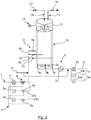
- the illustrated installation comprises sludge feed means 1 comprising a main pipe having two branches 1a, 1b.
- the main pipeline and its branches are each equipped on the one hand with pressurizing means 2, 2a, 2b, sludges each including a pump and on the other hand with mixing means 4, 4a, 4b with sludge pressurized with steam ( of water) each including a dynamic injector-mixer 18, 18a, 18b.
- the mixing means may include at least one in-line vapor diffuser (as defined above). Such diffusers are in particular marketed by ProSonix under the name " inline direct steam injection heater".
- the installation comprises means for supplying live steam 3 comprising a main line having two branches 3a and 3b respectively serving dynamic injector-mixers 18, 18a, 18b. These means for supplying live steam 3 are connected to a steam production plant (not shown in FIG. figure 1 ).
- the installation also comprises means 5 for distributing batches of sludge from said dynamic injectors-mixers 18, 18a, 18b alternatively in at least three reaction spaces 7a, 7b, 7c for the application of thermal hydrolysis cycles, cycles which will be described hereinafter in detail.
- each reaction space 7a, 7b, 7c is individualized by a reactor structure 19a, 19b, 19c respectively.
- each reaction space is delimited by the walls of a reactor independent of the other reactors delimiting the other reaction spaces.
- the distribution means 5 comprise three distribution lines 5a, 5b, 5c, each equipped with a sludge supply valve 6a, 6b, 6c respectively and making it possible to distribute batches of pressurized sludge and heated alternately in the three reaction spaces. 7a, 7b, 7c.
- the installation further comprises means 8 for evacuating batches of alternately hydrolysed sludge from each of the three reaction spaces 7a, 7b, 7c towards depressurization means 10, 10a, 10b each comprising a pump.
- These evacuation means 8 comprise three evacuation lines 8a, 8b, 8c, each equipped with a drain valve 9a, 9b, 9c making it possible to distribute the batches of hydrolysed sludge respectively to the depressurization means 10, 10a, 10b .
- the installation also comprises means of evacuation 11, 11a, 11b hydrolysed sludge each comprising a pipe.
- a heat exchanger 20 is provided on these means of evacuation in order to recover and / or evacuate part of the heat of the hydrolysed sludge discharged, which heat can be redirected to a steam generating plant or used to heat water. buildings or for other treatment such as digestion.
- the installation also comprises a water network 21 for diluting the sludge at the outlet of the reaction spaces.
- the heat exchanger 20 and the water network 21 constitute means for cooling the hydrolysed sludge.
- other cooling means may be used in the context of the present invention, such as in particular an injection of fresh sludge.
- the three reaction spaces 7a, 7b, 7c delimited by the walls of the reactors 19a, 19b, 19c, respectively, have a sky
- This common gaseous space is provided with means 13 for evacuating the gas present therein, including a valve 14, and means for injecting a gas 16 into the latter including an injection lance and A valve 17.
- the common gaseous sky 12 is further provided with means for measuring the pressure of the gas prevailing therein.
- the common gaseous sky is represented schematically on the figure 1 as an assembly covering the three reactors 19a, 19b, 19c. In practice it consists of all the upper parts of the three reactors 19a, 19b, 19c not filled with sludge and all the pipes from them to the valve 14.
- Sludge to be treated are mounted at a pressure of between 2 bar and 16 bar, preferably between 3.5 bar and 12 bar with pumps 2, 2a, 2b and then heated to temperature between 120 ° C and 200 ° C preferably between 140 ° C and 180 ° C through injectors-mixers 18, 18a, 18b. Thanks to such equipment, the sludge is intimately mixed with the steam and its viscosity is lowered, thus facilitating their subsequent processing.
- the hydrolysed sludge is cooled (here thanks to the heat exchanger 20 and the water supply via the network 21 but possibly by other means in the context of other embodiments) then depressurized by means of depressurization, and evacuated.
- the thermal hydrolysis treatment cycles are conducted in parallel in the three reaction spaces, the steps a), b), and c) of these cycles being shifted in time from a reaction space to the reaction zone. other.
- a batch of pressurized and heated sludge is brought during step a), said filling, in the reaction space 7a.
- the valve 6a serving the reaction space 7a is open and the drain valve 9a is closed.
- the reactor 19a delimiting the reaction space 7a is filled between 70% and 95% of its total volume capacity.
- the volume of the interior of the reactor not occupied by the sludge is occupied by a gaseous sky provided in the upper part of the reactor during step a).
- this step a) lasts twenty minutes.
- step b said thermal hydrolysis reaction, which in this example lasts twenty minutes also, the thermal hydrolysis of the sludge occurs, the supply valve 6a and the supply valve 9a remaining closed.
- valve 9a is open which causes, during a step c), the emptying of the contents of the batch of hydrolysed sludge contained in the reaction space 7a to the heat exchanger 20 then to the depressurizing means 10, 10a, 10b before their evacuation through the pipes of the evacuation means 11, 11a, 11b. Upstream of the exchanger 20 and downstream thereof water is brought to contribute to the cooling of the hydrolysed sludge by the water network 21.
- This step c) also lasts twenty minutes.
- steps a), b) and c) have a duration of twenty minutes and constitute a sixty minute processing cycle.
- This cycle is immediately repeated for one, then other batches of sludge to be treated in the reaction space 7a.
- Different sludge batch treatments succeed each other in a succession of sixty minute cycles during which these different batches of sludge pass through the reaction space 7a.
- the cycle starts of these different cycle successions are staggered in time so that the steps a) of a succession of cycles carried out in a first reaction space are concomitant with the steps b) of a another succession of cycles carried out in a second reaction space and in steps c) of another succession of cycles carried out in a third reaction space.
- this offset between the cycle starts of each succession of cycles is 20 minutes.
- valve 15 can be opened for a certain time to lower this pressure and the bring back to or around the reference pressure.
- valve 17 can be opened for a certain time to bring a gas (eg an inert gas or live steam) in this gaseous sky to increase this pressure and bring it back to, or around, the reference pressure.
- a gas eg an inert gas or live steam
- the embodiment described with reference to the figure 2 differs from that made with reference to the figure 1 that by the characteristic that the reaction spaces 7a, 7b, 7c are grouped into a single reactor structure 19 which they are portions and in that in-line vapor diffusers 22, 22a, 22b are used instead of injectors-mixers.
- the common gas head is constituted by the upper part of the reactor.
- the reactor has a vertical shape. In other embodiments, however, it may have a horizontal shape.
- the embodiment described with reference to the figure 3 differs from that described with reference to the figure 1 only by the characteristic that a backup tank 7d intended to act as a reaction space during the maintenance of one of the reaction spaces 7a, 7b and 7c.
- This vessel 7d can also be used to temporarily store sludge.
- the hydrolysed sludge is depressurized and cooled concomitantly in a flash tank 23 provided at the outlet of the reaction spaces 7a, 7b and 7c.
- Sludge cooling is perfect by injecting water into the sludge leaving this flash tank through the water network 21, before being evacuated via a pipe 15.
- the flash vapor emitted is conveyed via a line 25 to a pulper-mixer which also receives the incoming sludge.
- the incoming sludge can be preheated to a temperature for example between 50 and 100 ° C and preferably between 80 and 95 ° C.
- the incoming preheated sludge is then conveyed via a pipe 25a to the mixing means 4, 4a, 4b thereof with live steam.
- the remainder of the installation is in accordance with the embodiment given with reference to the figure 1 .
- the means for contacting the recovery steam with the incoming sludge may include other equipment than a pulper-mixer.
- the means for producing recovery steam may be other means than a flash tank. It may especially be a simple boiler recovery.
Landscapes
- Physics & Mathematics (AREA)
- Thermal Sciences (AREA)
- Life Sciences & Earth Sciences (AREA)
- Hydrology & Water Resources (AREA)
- Engineering & Computer Science (AREA)
- Environmental & Geological Engineering (AREA)
- Water Supply & Treatment (AREA)
- Chemical & Material Sciences (AREA)
- Organic Chemistry (AREA)
- Treatment Of Sludge (AREA)
Claims (23)
- Verfahren zur thermischen Hydrolyse von Schlamm, dadurch gekennzeichnet, dass es Folgendes umfasst:die Unter-Druck-Setzung des zu behandelnden Schlamms auf einen Referenzdruck im Bereich zwischen 2 bar a und 16 bar a,die Injektion von frischem Dampf in den unter Druck gesetzten Schlamm, um die Temperatur desselben auf zwischen 120 °C und 200 °C zu bringen,die Anwendung auf den unter Druck gesetzten und erhitzten Schlamm eines Behandlungszyklus der thermischen Hydrolyse, umfassend die folgenden Schritte:a) Leiten einer Menge von erhitztem und unter Druck gesetztem Schlamm in einen Reaktionsraum,b) Zurückhalten der Menge von Schlamm in dem Reaktionsraum während einer Dauer, die für seine thermische Hydrolyse ausreichend ist,c) Leerpumpen des Reaktionsraums von der Menge von Schlamm,die Abkühlung des hydrolysierten Schlamms,die Druckminderung des hydrolysierten Schlammsund seine Beseitigung,wobei die Anwendung auf den Schlamm eines Behandlungszyklus der thermischen Hydrolyse parallel in mindestens drei Reaktionsräumen durchgeführt wird, wobei in jedem derselben eine Aufeinanderfolge von Behandlungszyklen ausgeführt wird, wobei jeder der Reaktionsräume auf die Behandlung von verschiedenen Mengen von Schlamm ausgerichtet ist, wobei die Schritte a), b) und c) der Behandlungszyklen zeitlich von einem Reaktionsraum zum nächsten versetzt sind,wobei eine gemeinsame gasförmige Glocke für die mindestens drei Reaktionsräume angebracht ist und der Druck, der in der gemeinsamen gasförmigen Glocke herrscht, gemessen und im Wesentlichen konstant auf dem Referenzdruck gehalten wird.
- Verfahren nach Anspruch 1, dadurch gekennzeichnet, dass es einen Schritt des Anpassens des Drucks, der in der gemeinsamen gasförmigen Glocke herrscht, umfasst, wobei der Schritt des Anpassens die Injektion eines Gases in die gemeinsame gasförmige Glocke, wenn der Druck, der in derselben herrscht, geringer als eine vorbestimmte untere Schwelle ist, und/oder die Beseitigung eines Teils des Gases, das in der gemeinsamen gasförmigen Glocke vorhanden ist, umfasst, wenn der Druck, der in derselben herrscht, höher als eine vorbestimmte obere Schwelle ist.
- Verfahren nach Anspruch 2, dadurch gekennzeichnet, dass das Gas ausgewählt ist aus der Gruppe, bestehend aus frischem Dampf und einem inerten Gas.
- Verfahren nach einem der Ansprüche 2 oder 3, dadurch gekennzeichnet, dass der Schritt des Anpassens automatisch ist.
- Verfahren nach einem der Ansprüche 1 bis 4, dadurch gekennzeichnet, dass die Injektion von frischem Dampf in den unter Druck gesetzten Schlamm derart durchgeführt wird, dass der Schlamm auf eine Temperatur im Bereich zwischen 140 °C und 180 °C gebracht wird.
- Verfahren nach einem der Ansprüche 1 bis 5, dadurch gekennzeichnet, dass der Referenzdruck im Bereich zwischen 3,5 bar a und 10 bar a liegt.
- Verfahren nach einem der Ansprüche 1 bis 6, dadurch gekennzeichnet, dass die Injektion von Dampf dank Mitteln ausgeführt wird, enthalten in der Gruppe, bestehend aus den dynamischen Injektor-Mischern und den Dampfdiffusoren in Linie.
- Verfahren nach einem der Ansprüche 1 bis 7, dadurch gekennzeichnet, dass es das Vorerhitzen des eintretenden Schlamms vorgelagert von der Injektion von frischem Dampf umfasst.
- Verfahren nach Anspruch 8, dadurch gekennzeichnet, dass die Abkühlung des hydrolysierten Schlamms, Rückgewinnungsdampf erzeugt, und dadurch, dass es die Mischung aus Rückgewinnungsdampf mit dem eintretenden Schlamm für seine Vorerhitzung umfasst.
- Verfahren nach Anspruch 8 oder 9, dadurch gekennzeichnet, dass der Rückgewinnungsdampf in den Schlamm vorgelagert von dem Schritt des Injizierens von frischem Dampf dank mindestens einem Mittel injiziert wird, enthalten in der Gruppe, bestehend aus den dynamischen Injektor-Mischern, den Dampfdiffusoren in Linie und den Stofflöser-Mischern.
- Verfahren nach einem der Ansprüche 1 bis 10, dadurch gekennzeichnet, dass die Dauer von Schritt a) im Bereich zwischen 10 und 120 mn liegt, die Dauer von Schritt b) im Bereich zwischen 10 und 120 mn liegt, die Dauer von Schritt c) im Bereich zwischen 10 und 120 mn liegt.
- Verfahren nach einem der Ansprüche 1 bis 11, dadurch gekennzeichnet, dass die Menge von zu behandelndem Schlamm eine Trockenheit aufweist, die im Bereich zwischen 10 Gew% und 40 Gew% Trockenmasse liegt.
- Anlage zur Ausführung des Verfahrens nach einem der Ansprüche 1 bis 12, dadurch gekennzeichnet, dass sie Folgendes umfasst:Mittel zur Zuführung von Schlamm (1);Mittel zur Unter-Druck-Setzung (2, 2a, 2b) des Schlamms;Mittel zur Zuführung von frischem Dampf (3) und Mittel zur Mischung (4, 4a, 4b) des frischen Dampfs mit dem Schlamm;Mittel zur Verteilung (5) der Mengen von Schlamm von den Mitteln zur Mischung alternativ in mindestens drei Reaktionsräumen (7a, 7b, 7c) für die thermische Hydrolyse des Schlamms;Mittel zur Beseitigung (8) der Mengen von hydrolysiertem Schlamm alternativ von jedem der mindestens drei Reaktionsräume (7a, 7b, 7c) hin zu Mitteln zur Abkühlung und Mitteln zur Druckminderung (10, 10a, 10b) des hydrolysierten Schlamms;Mittel zur Entfernung (11, 11a, 11b) des druckgeminderten hydrolysierten Schlamms;wobei die mindestens drei Reaktionsräume (7a, 7b, 7c) eine gemeinsame gasförmige Glocke (12) aufweisen und die gemeinsame gasförmige Glocke mit Mitteln zur Entfernung von Gas (13) und Mitteln zur Messung des darin herrschenden Drucks (15) versehen ist.
- Anlage nach Anspruch 13, dadurch gekennzeichnet, dass die Mittel zur Mischung (4, 4a, 4b) des frischen Dampfs mit dem Schlamm mindestens einen dynamischen Injektor-Mischer (18, 18a, 18b) oder mindestens einen Dampfdiffusor in Linie (22, 22a, 22b) umfassen, der mit den Mitteln zur Zuführung von frischem Dampf verbunden ist.
- Anlage nach Anspruch 13 oder 14, dadurch gekennzeichnet, dass die gemeinsame gasförmige Glocke (12) mit Mitteln zur Injektion von Gas (16) versehen ist.
- Anlage nach einem der Ansprüche 13 bis 15, dadurch gekennzeichnet, dass die Reaktionsräume (7a, 7b, 7c) jeweils durch eine Reaktionsstruktur (19a, 19b, 19c) begrenzt sind.
- Anlage nach einem der Ansprüche 13 bis 16, dadurch gekennzeichnet, dass die Reaktionsräume (7a, 7b, 7c) in einer einzigen Reaktionsstruktur (19) zusammengefasst sind, wobei jeder der Reaktionsräume (7a, 7b, 7c) ein Abteil der einzigen Reaktionsstruktur (19) darstellt.
- Anlage nach einem der Ansprüche 14 bis 17, dadurch gekennzeichnet, dass sie eine Sicherheitswanne (7d) umfasst, die abgemessen ist, um mindestens eine Menge von Schlamm aufzunehmen, und Mittel zum Verteilen der Mengen von Schlamm von dem mindestens einen dynamischen Injektor-Mischer oder Dampfdiffusor in Linie hin zu der Sicherheitswanne (7d).
- Anlage nach einem der Ansprüche 13 bis 18, dadurch gekennzeichnet, dass die Mittel zum Abkühlen des hydrolysierten Schlamms, Mittel umfassen, ausgewählt aus der Gruppe, bestehend aus den Wärmetauschern (20), den Mitteln zum Verdünnen des hydrolysierten Schlamms mit Industriewasser, den Mitteln zur Injektion von frischem Schlamm in den hydrolysierten Schlamm, den Mitteln zum Erzeugen von Rückgewinnungsdampf.
- Anlage nach Anspruch 19, dadurch gekennzeichnet, dass sie mindestens einen Flashbehälter (23) umfasst, der den Rückgewinnungsdampf erzeugt.
- Anlage nach einem der Ansprüche 19 oder 20, dadurch gekennzeichnet, dass sie mindestens einen Kanal zur Zuführung (25, 25a) des Rückgewinnungsdampfs vorgelagert von den Mitteln zur Mischung (4, 4a, 4b) von frischem Dampf mit dem Schlamm und Mitteln zur In-Kontakt-Bringung des Rückgewinnungsdampfs mit dem zu behandelnden Schlamm umfasst.
- Anlage nach Anspruch 21, dadurch gekennzeichnet, dass die Mittel zur In-Kontakt-Bringung mindestens ein Mittel einschießen, ausgewählt aus den dynamischen Injektor-Mischern, den Dampfdiffusoren in Linie und den Stofflöser-Mischern (24).
- Anlage nach Anspruch 19, dadurch gekennzeichnet, dass die Mittel zur Abkühlung des hydrolysierten Schlamms, einen Wärmetauscher vom Typ Schlamm-Schlamm-Tauscher einschließen.
Priority Applications (1)
| Application Number | Priority Date | Filing Date | Title |
|---|---|---|---|
| PL16736199T PL3328802T3 (pl) | 2015-07-31 | 2016-07-08 | Sposób i instalacja do półciągłej hydrolizy termicznej osadu |
Applications Claiming Priority (2)
| Application Number | Priority Date | Filing Date | Title |
|---|---|---|---|
| FR1557397A FR3039533B1 (fr) | 2015-07-31 | 2015-07-31 | Procede et installation pour l'hydrolyse thermique semi-continue des boues. |
| PCT/EP2016/066255 WO2017021097A1 (fr) | 2015-07-31 | 2016-07-08 | Procede et installation pour l'hydrolyse thermique semi-continue des boues |
Publications (2)
| Publication Number | Publication Date |
|---|---|
| EP3328802A1 EP3328802A1 (de) | 2018-06-06 |
| EP3328802B1 true EP3328802B1 (de) | 2018-10-03 |
Family
ID=54707906
Family Applications (1)
| Application Number | Title | Priority Date | Filing Date |
|---|---|---|---|
| EP16736199.7A Active EP3328802B1 (de) | 2015-07-31 | 2016-07-08 | Verfahren und anlage zur halbkontinuierlichen thermischen hydrolyse von schlamm |
Country Status (8)
| Country | Link |
|---|---|
| EP (1) | EP3328802B1 (de) |
| CN (1) | CN107848853B (de) |
| CA (1) | CA2992657C (de) |
| DK (1) | DK3328802T3 (de) |
| FR (1) | FR3039533B1 (de) |
| HK (1) | HK1254616B (de) |
| PL (1) | PL3328802T3 (de) |
| WO (1) | WO2017021097A1 (de) |
Families Citing this family (1)
| Publication number | Priority date | Publication date | Assignee | Title |
|---|---|---|---|---|
| EP3898999A1 (de) | 2018-12-17 | 2021-10-27 | Cambi Technology AS | Zweifach-zwei-tankverfahren und -system |
Family Cites Families (9)
| Publication number | Priority date | Publication date | Assignee | Title |
|---|---|---|---|---|
| NO310717B1 (no) * | 1999-05-31 | 2001-08-20 | Cambi As | Fremgangsmate og anordning for kontinuerlig hydrolyse av avlopsvann |
| FR2820735B1 (fr) | 2001-02-14 | 2004-05-14 | Vivendi Water Systems | Procede et installation pour l'hydrolyse thermique des boues |
| NO330122B1 (no) * | 2009-07-13 | 2011-02-21 | Cambi As | Fremgangsmate og anordning for termisk hydrolyse av biomasse og dampeksplosjon av biomasse |
| CN102417285B (zh) * | 2011-10-20 | 2013-05-01 | 同济大学 | 一种高含固生物污泥连续热水解装置与方法 |
| CN102424508A (zh) * | 2011-10-28 | 2012-04-25 | 广西博世科环保科技股份有限公司 | 一种高效回收热能的污泥热解消化工艺及其设备 |
| FR2990429B1 (fr) | 2012-05-10 | 2014-06-13 | Veolia Water Solutions & Tech | Procede et installation pour l'hydrolyse thermique des boues |
| CN102775031B (zh) * | 2012-06-26 | 2015-02-25 | 深圳市环源科技发展有限公司 | 污泥加碱加酸催化双热水解处理方法 |
| FR3010403B1 (fr) | 2013-09-06 | 2017-01-13 | Veolia Water Solutions & Tech | Procede et dispositif d'hydrolyse thermique en continu avec recirculation de vapeur de recuperation |
| FR3015971B1 (fr) * | 2013-12-26 | 2016-01-01 | Veolia Water Solutions & Tech | Procede d'hydrolyse thermique en continu de boues a forte siccite. |
-
2015
- 2015-07-31 FR FR1557397A patent/FR3039533B1/fr not_active Expired - Fee Related
-
2016
- 2016-07-08 HK HK18113582.7A patent/HK1254616B/zh unknown
- 2016-07-08 WO PCT/EP2016/066255 patent/WO2017021097A1/fr not_active Ceased
- 2016-07-08 CA CA2992657A patent/CA2992657C/en active Active
- 2016-07-08 CN CN201680044991.0A patent/CN107848853B/zh active Active
- 2016-07-08 PL PL16736199T patent/PL3328802T3/pl unknown
- 2016-07-08 DK DK16736199.7T patent/DK3328802T3/en active
- 2016-07-08 EP EP16736199.7A patent/EP3328802B1/de active Active
Non-Patent Citations (1)
| Title |
|---|
| None * |
Also Published As
| Publication number | Publication date |
|---|---|
| WO2017021097A1 (fr) | 2017-02-09 |
| CN107848853B (zh) | 2019-07-16 |
| FR3039533A1 (fr) | 2017-02-03 |
| CN107848853A (zh) | 2018-03-27 |
| EP3328802A1 (de) | 2018-06-06 |
| CA2992657A1 (en) | 2017-02-09 |
| CA2992657C (en) | 2019-08-20 |
| HK1254616B (zh) | 2020-03-27 |
| FR3039533B1 (fr) | 2017-08-11 |
| DK3328802T3 (en) | 2019-01-28 |
| PL3328802T3 (pl) | 2019-04-30 |
Similar Documents
| Publication | Publication Date | Title |
|---|---|---|
| EP3041796B1 (de) | Verfahren und vorrichtung für kontinuierliche thermische hydrolyse mit rezirkulation von wiedergewonnenem dampf | |
| EP3212582B1 (de) | Verfahren und anlage zur thermischen hydrolyse von schlämme | |
| FR2820735A1 (fr) | Procede et installation pour l'hydrolyse thermique des boues | |
| EP3152167B1 (de) | Hydrothermalkarbonisationsverfahren und vorrichtung mit optimiertem schlamm- und dampfmischen | |
| EP3287418B1 (de) | Verfahren zur ultra-entwässerung von verdickten oder pastösen produkten, die eine biomasse bilden, und anlage zur umsetzung dieses verfahrens | |
| FR3037057B1 (fr) | Procede et dispositif de carbonisation hydrothermale a rendement energetique optimise | |
| EP3087038B1 (de) | Verfahren zur kontinuierlichen thermischen hydrolyse von schlämmen mit hohem trockenheitswert | |
| FR3003558A1 (fr) | Procede et dispositif d’hydrolyse thermique en continu | |
| WO2013167469A1 (fr) | Procede et installation pour l'hydrolyse thermique des boues | |
| CA2679437A1 (fr) | Procede de fabrication de charbon vegetal a haute teneur en carbone et l'installation de mise en oeuvre du procede | |
| EP3328802B1 (de) | Verfahren und anlage zur halbkontinuierlichen thermischen hydrolyse von schlamm | |
| HK1254616A1 (en) | Process and facility for semi-continuous thermal hydrolysis of sludge | |
| FR2947043A1 (fr) | Dispositif de sechage d'un dechet et procede correspondant. | |
| FR2874078A1 (fr) | Procede de refroidissement sous pression reduite et installation pour sa mise en oeuvre | |
| FR2960871A1 (fr) | Procede et installation de sechage par deshydratation mecanique par pressage de matieres pateuses, en particulier de boues de stations d'epuration | |
| FR2947044A1 (fr) | Dispositif de sechage de dechets par evaporation et procede correspondant. | |
| EP2207873A1 (de) | Anaerobe verdauungsvorrichtung mit spülung und fixiertem biofilm | |
| WO2024068896A1 (fr) | Procede de traitement de dechets organiques | |
| FR3118631A1 (fr) | Dispositif et procédé pour la production d’acides gras volatils à partir de coquilles de mollusques présentant des corps mous ou de la chair | |
| WO2016026058A1 (fr) | Procédé de préparation de biomasse lignocellulosique pour la production de produits de bio-raffinerie et notamment d'éthanol et installation pour la mise en oeuvre de ce procédé | |
| CA3152843A1 (fr) | Appareil et methode pour revaloriser differents residus organiques et industriels | |
| BE523694A (de) | ||
| BE496490A (de) |
Legal Events
| Date | Code | Title | Description |
|---|---|---|---|
| STAA | Information on the status of an ep patent application or granted ep patent |
Free format text: STATUS: THE INTERNATIONAL PUBLICATION HAS BEEN MADE |
|
| PUAI | Public reference made under article 153(3) epc to a published international application that has entered the european phase |
Free format text: ORIGINAL CODE: 0009012 |
|
| STAA | Information on the status of an ep patent application or granted ep patent |
Free format text: STATUS: REQUEST FOR EXAMINATION WAS MADE |
|
| 17P | Request for examination filed |
Effective date: 20171207 |
|
| AK | Designated contracting states |
Kind code of ref document: A1 Designated state(s): AL AT BE BG CH CY CZ DE DK EE ES FI FR GB GR HR HU IE IS IT LI LT LU LV MC MK MT NL NO PL PT RO RS SE SI SK SM TR |
|
| AX | Request for extension of the european patent |
Extension state: BA ME |
|
| GRAP | Despatch of communication of intention to grant a patent |
Free format text: ORIGINAL CODE: EPIDOSNIGR1 |
|
| STAA | Information on the status of an ep patent application or granted ep patent |
Free format text: STATUS: GRANT OF PATENT IS INTENDED |
|
| INTG | Intention to grant announced |
Effective date: 20180618 |
|
| GRAS | Grant fee paid |
Free format text: ORIGINAL CODE: EPIDOSNIGR3 |
|
| GRAA | (expected) grant |
Free format text: ORIGINAL CODE: 0009210 |
|
| STAA | Information on the status of an ep patent application or granted ep patent |
Free format text: STATUS: THE PATENT HAS BEEN GRANTED |
|
| DAV | Request for validation of the european patent (deleted) | ||
| DAX | Request for extension of the european patent (deleted) | ||
| AK | Designated contracting states |
Kind code of ref document: B1 Designated state(s): AL AT BE BG CH CY CZ DE DK EE ES FI FR GB GR HR HU IE IS IT LI LT LU LV MC MK MT NL NO PL PT RO RS SE SI SK SM TR |
|
| REG | Reference to a national code |
Ref country code: GB Ref legal event code: FG4D Free format text: NOT ENGLISH |
|
| REG | Reference to a national code |
Ref country code: AT Ref legal event code: REF Ref document number: 1048391 Country of ref document: AT Kind code of ref document: T Effective date: 20181015 Ref country code: CH Ref legal event code: EP |
|
| REG | Reference to a national code |
Ref country code: DE Ref legal event code: R096 Ref document number: 602016006254 Country of ref document: DE Ref country code: IE Ref legal event code: FG4D Free format text: LANGUAGE OF EP DOCUMENT: FRENCH |
|
| REG | Reference to a national code |
Ref country code: DK Ref legal event code: T3 Effective date: 20190122 |
|
| REG | Reference to a national code |
Ref country code: NL Ref legal event code: FP |
|
| REG | Reference to a national code |
Ref country code: NO Ref legal event code: T2 Effective date: 20181003 Ref country code: LT Ref legal event code: MG4D |
|
| REG | Reference to a national code |
Ref country code: AT Ref legal event code: MK05 Ref document number: 1048391 Country of ref document: AT Kind code of ref document: T Effective date: 20181003 |
|
| PG25 | Lapsed in a contracting state [announced via postgrant information from national office to epo] |
Ref country code: FI Free format text: LAPSE BECAUSE OF FAILURE TO SUBMIT A TRANSLATION OF THE DESCRIPTION OR TO PAY THE FEE WITHIN THE PRESCRIBED TIME-LIMIT Effective date: 20181003 Ref country code: LV Free format text: LAPSE BECAUSE OF FAILURE TO SUBMIT A TRANSLATION OF THE DESCRIPTION OR TO PAY THE FEE WITHIN THE PRESCRIBED TIME-LIMIT Effective date: 20181003 Ref country code: LT Free format text: LAPSE BECAUSE OF FAILURE TO SUBMIT A TRANSLATION OF THE DESCRIPTION OR TO PAY THE FEE WITHIN THE PRESCRIBED TIME-LIMIT Effective date: 20181003 Ref country code: ES Free format text: LAPSE BECAUSE OF FAILURE TO SUBMIT A TRANSLATION OF THE DESCRIPTION OR TO PAY THE FEE WITHIN THE PRESCRIBED TIME-LIMIT Effective date: 20181003 Ref country code: CZ Free format text: LAPSE BECAUSE OF FAILURE TO SUBMIT A TRANSLATION OF THE DESCRIPTION OR TO PAY THE FEE WITHIN THE PRESCRIBED TIME-LIMIT Effective date: 20181003 Ref country code: IS Free format text: LAPSE BECAUSE OF FAILURE TO SUBMIT A TRANSLATION OF THE DESCRIPTION OR TO PAY THE FEE WITHIN THE PRESCRIBED TIME-LIMIT Effective date: 20190203 Ref country code: AT Free format text: LAPSE BECAUSE OF FAILURE TO SUBMIT A TRANSLATION OF THE DESCRIPTION OR TO PAY THE FEE WITHIN THE PRESCRIBED TIME-LIMIT Effective date: 20181003 Ref country code: HR Free format text: LAPSE BECAUSE OF FAILURE TO SUBMIT A TRANSLATION OF THE DESCRIPTION OR TO PAY THE FEE WITHIN THE PRESCRIBED TIME-LIMIT Effective date: 20181003 Ref country code: BG Free format text: LAPSE BECAUSE OF FAILURE TO SUBMIT A TRANSLATION OF THE DESCRIPTION OR TO PAY THE FEE WITHIN THE PRESCRIBED TIME-LIMIT Effective date: 20190103 |
|
| PG25 | Lapsed in a contracting state [announced via postgrant information from national office to epo] |
Ref country code: PT Free format text: LAPSE BECAUSE OF FAILURE TO SUBMIT A TRANSLATION OF THE DESCRIPTION OR TO PAY THE FEE WITHIN THE PRESCRIBED TIME-LIMIT Effective date: 20190203 Ref country code: GR Free format text: LAPSE BECAUSE OF FAILURE TO SUBMIT A TRANSLATION OF THE DESCRIPTION OR TO PAY THE FEE WITHIN THE PRESCRIBED TIME-LIMIT Effective date: 20190104 Ref country code: SE Free format text: LAPSE BECAUSE OF FAILURE TO SUBMIT A TRANSLATION OF THE DESCRIPTION OR TO PAY THE FEE WITHIN THE PRESCRIBED TIME-LIMIT Effective date: 20181003 Ref country code: RS Free format text: LAPSE BECAUSE OF FAILURE TO SUBMIT A TRANSLATION OF THE DESCRIPTION OR TO PAY THE FEE WITHIN THE PRESCRIBED TIME-LIMIT Effective date: 20181003 Ref country code: AL Free format text: LAPSE BECAUSE OF FAILURE TO SUBMIT A TRANSLATION OF THE DESCRIPTION OR TO PAY THE FEE WITHIN THE PRESCRIBED TIME-LIMIT Effective date: 20181003 |
|
| REG | Reference to a national code |
Ref country code: DE Ref legal event code: R097 Ref document number: 602016006254 Country of ref document: DE |
|
| REG | Reference to a national code |
Ref country code: HK Ref legal event code: DE Ref document number: 1254616 Country of ref document: HK |
|
| PLBE | No opposition filed within time limit |
Free format text: ORIGINAL CODE: 0009261 |
|
| STAA | Information on the status of an ep patent application or granted ep patent |
Free format text: STATUS: NO OPPOSITION FILED WITHIN TIME LIMIT |
|
| PG25 | Lapsed in a contracting state [announced via postgrant information from national office to epo] |
Ref country code: EE Free format text: LAPSE BECAUSE OF FAILURE TO SUBMIT A TRANSLATION OF THE DESCRIPTION OR TO PAY THE FEE WITHIN THE PRESCRIBED TIME-LIMIT Effective date: 20181003 Ref country code: SK Free format text: LAPSE BECAUSE OF FAILURE TO SUBMIT A TRANSLATION OF THE DESCRIPTION OR TO PAY THE FEE WITHIN THE PRESCRIBED TIME-LIMIT Effective date: 20181003 Ref country code: SM Free format text: LAPSE BECAUSE OF FAILURE TO SUBMIT A TRANSLATION OF THE DESCRIPTION OR TO PAY THE FEE WITHIN THE PRESCRIBED TIME-LIMIT Effective date: 20181003 Ref country code: RO Free format text: LAPSE BECAUSE OF FAILURE TO SUBMIT A TRANSLATION OF THE DESCRIPTION OR TO PAY THE FEE WITHIN THE PRESCRIBED TIME-LIMIT Effective date: 20181003 |
|
| 26N | No opposition filed |
Effective date: 20190704 |
|
| PG25 | Lapsed in a contracting state [announced via postgrant information from national office to epo] |
Ref country code: MC Free format text: LAPSE BECAUSE OF FAILURE TO SUBMIT A TRANSLATION OF THE DESCRIPTION OR TO PAY THE FEE WITHIN THE PRESCRIBED TIME-LIMIT Effective date: 20181003 |
|
| REG | Reference to a national code |
Ref country code: CH Ref legal event code: PL |
|
| PG25 | Lapsed in a contracting state [announced via postgrant information from national office to epo] |
Ref country code: TR Free format text: LAPSE BECAUSE OF FAILURE TO SUBMIT A TRANSLATION OF THE DESCRIPTION OR TO PAY THE FEE WITHIN THE PRESCRIBED TIME-LIMIT Effective date: 20181003 |
|
| REG | Reference to a national code |
Ref country code: BE Ref legal event code: MM Effective date: 20190731 |
|
| PG25 | Lapsed in a contracting state [announced via postgrant information from national office to epo] |
Ref country code: BE Free format text: LAPSE BECAUSE OF NON-PAYMENT OF DUE FEES Effective date: 20190731 Ref country code: CH Free format text: LAPSE BECAUSE OF NON-PAYMENT OF DUE FEES Effective date: 20190731 Ref country code: LU Free format text: LAPSE BECAUSE OF NON-PAYMENT OF DUE FEES Effective date: 20190708 Ref country code: LI Free format text: LAPSE BECAUSE OF NON-PAYMENT OF DUE FEES Effective date: 20190731 |
|
| PG25 | Lapsed in a contracting state [announced via postgrant information from national office to epo] |
Ref country code: IE Free format text: LAPSE BECAUSE OF NON-PAYMENT OF DUE FEES Effective date: 20190708 |
|
| GBPC | Gb: european patent ceased through non-payment of renewal fee |
Effective date: 20200708 |
|
| PG25 | Lapsed in a contracting state [announced via postgrant information from national office to epo] |
Ref country code: GB Free format text: LAPSE BECAUSE OF NON-PAYMENT OF DUE FEES Effective date: 20200708 |
|
| PG25 | Lapsed in a contracting state [announced via postgrant information from national office to epo] |
Ref country code: CY Free format text: LAPSE BECAUSE OF FAILURE TO SUBMIT A TRANSLATION OF THE DESCRIPTION OR TO PAY THE FEE WITHIN THE PRESCRIBED TIME-LIMIT Effective date: 20181003 |
|
| PG25 | Lapsed in a contracting state [announced via postgrant information from national office to epo] |
Ref country code: MT Free format text: LAPSE BECAUSE OF FAILURE TO SUBMIT A TRANSLATION OF THE DESCRIPTION OR TO PAY THE FEE WITHIN THE PRESCRIBED TIME-LIMIT Effective date: 20181003 Ref country code: HU Free format text: LAPSE BECAUSE OF FAILURE TO SUBMIT A TRANSLATION OF THE DESCRIPTION OR TO PAY THE FEE WITHIN THE PRESCRIBED TIME-LIMIT; INVALID AB INITIO Effective date: 20160708 |
|
| PG25 | Lapsed in a contracting state [announced via postgrant information from national office to epo] |
Ref country code: SI Free format text: LAPSE BECAUSE OF FAILURE TO SUBMIT A TRANSLATION OF THE DESCRIPTION OR TO PAY THE FEE WITHIN THE PRESCRIBED TIME-LIMIT Effective date: 20181003 |
|
| PG25 | Lapsed in a contracting state [announced via postgrant information from national office to epo] |
Ref country code: MK Free format text: LAPSE BECAUSE OF FAILURE TO SUBMIT A TRANSLATION OF THE DESCRIPTION OR TO PAY THE FEE WITHIN THE PRESCRIBED TIME-LIMIT Effective date: 20181003 |
|
| P01 | Opt-out of the competence of the unified patent court (upc) registered |
Effective date: 20230516 |
|
| PGFP | Annual fee paid to national office [announced via postgrant information from national office to epo] |
Ref country code: NL Payment date: 20250715 Year of fee payment: 10 |
|
| PGFP | Annual fee paid to national office [announced via postgrant information from national office to epo] |
Ref country code: DK Payment date: 20250723 Year of fee payment: 10 Ref country code: DE Payment date: 20250721 Year of fee payment: 10 |
|
| PGFP | Annual fee paid to national office [announced via postgrant information from national office to epo] |
Ref country code: NO Payment date: 20250722 Year of fee payment: 10 |
|
| PGFP | Annual fee paid to national office [announced via postgrant information from national office to epo] |
Ref country code: PL Payment date: 20250702 Year of fee payment: 10 Ref country code: IT Payment date: 20250728 Year of fee payment: 10 |
|
| PGFP | Annual fee paid to national office [announced via postgrant information from national office to epo] |
Ref country code: FR Payment date: 20250716 Year of fee payment: 10 |