EP3329057B1 - Améliorations apportées au drainage ou se rapportant à celui-ci - Google Patents
Améliorations apportées au drainage ou se rapportant à celui-ci Download PDFInfo
- Publication number
- EP3329057B1 EP3329057B1 EP16833393.8A EP16833393A EP3329057B1 EP 3329057 B1 EP3329057 B1 EP 3329057B1 EP 16833393 A EP16833393 A EP 16833393A EP 3329057 B1 EP3329057 B1 EP 3329057B1
- Authority
- EP
- European Patent Office
- Prior art keywords
- floor
- channel
- sides
- drainage channel
- fluid
- Prior art date
- Legal status (The legal status is an assumption and is not a legal conclusion. Google has not performed a legal analysis and makes no representation as to the accuracy of the status listed.)
- Active
Links
Images



Classifications
-
- E—FIXED CONSTRUCTIONS
- E03—WATER SUPPLY; SEWERAGE
- E03F—SEWERS; CESSPOOLS
- E03F5/00—Sewerage structures
- E03F5/04—Gullies inlets, road sinks, floor drains with or without odour seals or sediment traps
- E03F5/0407—Floor drains for indoor use
-
- A—HUMAN NECESSITIES
- A47—FURNITURE; DOMESTIC ARTICLES OR APPLIANCES; COFFEE MILLS; SPICE MILLS; SUCTION CLEANERS IN GENERAL
- A47K—SANITARY EQUIPMENT; ACCESSORIES THEREFOR, e.g. TOILET ACCESSORIES
- A47K3/00—Baths; Showers; Appurtenances therefor
- A47K3/28—Showers or bathing douches
-
- E—FIXED CONSTRUCTIONS
- E03—WATER SUPPLY; SEWERAGE
- E03C—DOMESTIC PLUMBING INSTALLATIONS FOR FRESH WATER OR WASTE WATER; SINKS
- E03C1/00—Domestic plumbing installations for fresh water or waste water; Sinks
- E03C1/12—Plumbing installations for waste water; Basins or fountains connected thereto; Sinks
- E03C1/22—Outlet devices mounted in basins, baths, or sinks
-
- E—FIXED CONSTRUCTIONS
- E03—WATER SUPPLY; SEWERAGE
- E03F—SEWERS; CESSPOOLS
- E03F5/00—Sewerage structures
- E03F5/04—Gullies inlets, road sinks, floor drains with or without odour seals or sediment traps
- E03F5/0407—Floor drains for indoor use
- E03F5/0409—Devices for preventing seepage around the floor drain
Definitions
- the present invention relates to drainage.
- the present invention is directed to a drainage channel according to claim 1 and a corresponding method of installing a drainage channel according to claim 7.
- a circular drain is often provided in the building floor, which is then connected to a waste outlet to drain the water away.
- a further disadvantage of existing systems is the requirement to provide differing heights between any mounting flange at the top of the drain to account for differing floor finish thicknesses. This is because only one height of covering is provided and the in floor drain must then be provided with the correct depth to place the top of the covering at the desired level, typically flush, with the surrounding floor surface. This results in more stock of drains that needs to be held to account for a variety of finishes, heights and installed lengths. This is a clear disadvantage as generally all combinations must be provided or kept in stock, with the resulting cost of product, storage and potentially wastage of unused product.
- EP1577452A2 discloses a drainage channel for discharging a liquid comprising a duct part comprising a bottom wall and upright longitudinal side walls and a horizontal waste.
- US1809549A discloses a member adapted to be inserted into a roof structure which has a cupped recess into which the membrane covering the roof structure is sealed by an inserted cap placed over the roof membrane.
- EP2808457A2 discloses a water drainage device for a sanitary system, such as a floorlevel shower enclosure - A trough-shaped water drainage element, which is fluidly connected to a drain pipe or connectable with thread-wise adjustable supports.
- US2011/203979A1 discloses a floor drain comprising a channel body defining a drain channel and having a drain opening, a frame defining a receiving opening which can be inserted at least partially into the drain channel and a cover that can be inserted into the receiving opening of the frame.
- US2010/162481A1 discloses elongated drain assemblies suitable for use in tiled shower stalls.
- the assemblies include an elongated trough having a trough length at least seven times a trough width, the trough including a bottom side and a discharge opening located generally proximate longitudinal middle of the trough, the bottom side including a left portion sloping downwardly towards the discharge opening and a right portion sloping downwardly towards the discharge opening.
- the present invention consists in a drainage channel adapted to receive fluid from a building floor and drain it to a waste outlet, said channel comprising:
- the drainage channel requires no support from below, it is only secured in place by the planar flanges.
- any necessary waterproofing and floor finishing is located over the top of the planar flanges.
- the waterproofing extends from the planar flanges at least in part down into the channel.
- the floors and walls allow for waterproofing and floor finishing to be applied to the building floor over the planar flanges and at least in part down into the upwardly open channel.
- the drainage channel is formed from a thin walled material, comprising:
- the drainage channel has the planar flanges on at least two or more sides.
- a third one of the sides adjacent the first one and/or the second one of the sides has a substantially planar flange extending outwardly or upwardly therefrom; and/or a fourth one of the sides adjacent the first one and/or the second one of the sides has a substantially planar flange extending outwardly or upwardly therefrom.
- the substantially planar flange of the third one of the sides is joined together to the substantially planar flange of the first one and/or the second one of the sides; and/or the substantially planar flange of the fourth one of the sides is joined to the substantially planar flange of the first one and/or second one of the sides.
- planar flanges that are adjacent each other and extending outwardly are joined together.
- planar flanges that are adjacent each other and extending upwardly are joined together.
- those sides adjacent a wall have upwardly extending substantially planar flanges.
- those sides adjacent a building floor have outwardly extending substantially planar flanges.
- planar flanges are secured to the building floor and walls using penetrative fastenings through the planar flanges and into the floor and walls.
- said channel is located in a building floor in any one or more of the following locations,
- the channel is manufactured in certain standard lengths and is also cut and formed to the length as needed.
- Preferably all that is needed to specify the drainage channel for installation is the length that is required of the channel.
- all that is needed to specify the grate is the height of the upper surface of the floor above the floor portion to in turn adjust the height of the upstands.
- first one of the sides and the second one of the sides are parallel and opposed to each other.
- the present invention consists in a method of installing a drainage channel adapted to receive fluid from a building floor and drain it to a waste outlet, comprising the steps of:
- planar flanges are secured to the building floor and walls using penetrative fastenings through the planar flanges and into the floor and walls.
- a finishing on a surrounding wall extends down past the periphery of the upwardly open channel.
- the sides adjacent a wall have upwardly extending substantially planar flanges.
- those sides adjacent a building floor have outwardly extending substantially planar flanges.
- said channel is located in a building floor in any one or more of the following locations,
- the method includes the step of sizing a length of the channel to a length of the building floor aperture.
- the present invention may be said to broadly consist in a kit of parts for a drainage channel adapted to receive fluid from a building floor and drain it to a waste outlet, comprising or including,
- kit is supplied with penetrative fastenings to secure the substantially planar flanges to a building floor and (if present) a wall.
- the kit is supplied with a sealing gaskets for the waste outlet.
- the present invention may be said to broadly consist in a drainage channel as described herein with reference to any one or more of the accompanying drawings.
- the present invention consists in a method of installing or providing a drainage channel as described herein with reference to any one or more of the accompanying drawings.
- the present invention consists in a kit of parts as described herein with reference to any one or more of the accompanying drawings.
- the preferred function of the present invention is to prevent damage due to flow of fluids where they are not desired. For example to ensure fluid in a shower or bathroom drains away, for example by providing a drainage channel within the shower or bathroom, or at least within the designated wet, or waterproofed area. Further the present invention can be used to drain away fluids that result from cleaning, e.g. floor cleaning products that may for example be used in a kitchen or similar.
- the present invention may be used as a safety drain to prevent a fluid that is accidentally spilt or that overflows, from moving into an area where it may contain damage, for example in a laundry near a washing machine or dishwasher, or under or beside a door as a threshold or similar, between one room, for example a bathroom, that water will not damage and that may be the source of the fluid, to another room where it is desired to not have fluid flow, for example a hallway.
- Such containment may be a single story building, but also will prove highly desirable when in a multi-storey building to contain fluid within a waterproofed area and prevent it migrating to a non-waterproofed area, for example a hallway, where it would otherwise damage the structure, eg ceiling or floor, below.
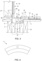
- a first embodiment of the drainage channel 1 is shown in Figures 1 through 4 .
- the drainage channel 1 as shown has a channel 4 that is upwardly open and is defined by a lowermost floor portion 25, and sides 5 that define an uppermost periphery 6 of the channel 4 as shown in Figures 1 and 2 .
- Depending from the upper most periphery 6 are substantially planar flanges 7 that extend outwardly 7A and upwardly 7B.
- those flanges 7 that are adjacent each other are joined, such as the upward planar flanges 7B. The function of these will be described below.
- a waste aperture 8 Located in the lowermost point of the channel 4, that is, in the floor portion 25 is a waste aperture 8. This has an extension as a spigot as shown that allows for connection with a waste outlet 3 (see Figure 3 ), for example by threaded connection or other known connection, for drainage of fluid to the normal grey water or sewage connection (not shown).
- pre-made fastener holes 26 Shown also are pre-made fastener holes 26 to allow for penetrative fasteners. By providing such pre-made holes it is indicated the number and spacing of fasteners that are required to safely and correctly mount the channel to hold the loads that may be applied to it to prevent structural failure, and more importantly to prevent failure of the waterproof membrane or region which the channel forms an integral part of.
- the penetrative fasteners may be ones that are of the self-drilling type and no holes are needed.
- the present invention is made from folded steel sheet, for example stainless steel that is folded to form an open channel form and then ends are either folded up or welded into place to form the channel 1.
- the channel 1 may be made from other materials, such as, but not limited to, plastics materials and may be folded or extruded, or moulded.
- the channel may be made in an indefinite length and then cut or formed to size as needed.
- the channel 1 is also not limited to a rectangular form as shown, but may for example be curved as shown in Figure 4 , for example. Such curved form is desirable aesthetically, and also conveys the further secondary advantage of preventing build up or materials, and allowing ease of cleaning.
- the general installation of the drainage channel 1 is shown in Figure 3 , in this example the drainage channel is located in a corner of a room along, and against, part of a wall 15.
- An aperture 13 is shown cut into a building floor 2, along that part of the wall 15.
- the building floor 2 is supported in the normal way for a building as shown.
- the channel 1 is lowered into place in the aperture 13.
- the installer may add waterproofing, adhesive or sealant to the underside of the planar flanges 7 to seal against for example the sides or other surfaces of the aperture 13.
- Penetrative fasteners are then driven through the planar flanges 7 into the substrate below.
- the fasteners are driven into the building floor 2 (and framing 27 there under), and for upward flanges 7B then are driven into the surrounding walls 15 (and framing 27 there behind).
- framing 27 is provided at the periphery of the aperture and behind the wall 15 to support the floor 2 and wall 15, and also to receive the penetrative fastenings from the planar flanges 7.
- waterproofing 17 extends at least in part down the sides 5 into the channel 4.
- a finishing 12 can then be applied for example tiles or similar.
- the finishing 12 on the floor extends up to the edge of the channel 4, and on the walls 15 it extends below the lower surface of the floor finishing 12 as shown.
- a grate with grate apertures 29 therein is then located in the channel 2.
- the grate has upstands 10 along its length that rest on the lowermost floor portion 25.
- the upstands can be adjusted in height, either by a threaded connection, or simply cutting them to length.
- the desired height is set so the upper surface 11 of the grate is substantially flush with the upper level of the floor finishing 12.
- the grate may also be able to receive a finish on its upper surface 11 to match or otherwise compliment the floor finishing.
- the waste outlet 3 is connected to the waste aperture 8.
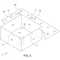
- FIG. 5 A second embodiment of the drainage channel for in floor draining, for example for spills and cleaning fluids is shown in Figures 5 through 7 .
- the channel 4 has a floor portion 25 surrounded by sides 5 to define a periphery 6 and the channel 4. Extending outwardly from the periphery 6 from each side 5 is an outward planar flange 7A (shown broken away in part for clarity). These planar flanges as they are adjacent are joined. In the preferred form the planar flanges 7A have fastener holes 26.
- An installation of the channel 1 is shown in Figure 7 .
- the channel 1 is installed in a similar manner to that described for the first embodiment and the same integers apply here.
- the main difference is the channel 1 here as all outward planar flanges 7A, for example at least on two parallel sides, preferably the longer sides, as it is not installed against a wall.
- FIG. 7 The general installation of the drainage channel 1 is shown in Figure 7 , in this example the drainage channel is located in a floor of a room. An aperture 13 is shown cut into a building floor 2. The building floor 2 is supported in the normal way for a building as shown using framing 27. The channel 1 is lowered into place in the aperture 13. Again no under channel framing support is needed.
- the installer may add waterproofing, adhesive or sealant to the underside of the planar flanges 7 to seal against for example the sides or other surfaces of the aperture 13.
- Penetrative fasteners are then driven through the planar flanges 7 into the substrate below.
- the fasteners are driven into the building floor 2 (and framing 27 there under).
- framing 27 is provided at the periphery of the aperture to support the floor 2 and wall 15, and also to receive the penetrative fastenings from the planar flanges 7.
- waterproofing 17 extends at least in part down the sides 5 into the channel 4.
- a finishing 12 can then be applied for example tiles or similar.
- the finishing 12 on the floor extends up to the edge of the channel 4 as shown.
- a grate with grate apertures 29 therein is then located in the channel 2.
- the grate has upstands 10 along its length that rest on the lowermost floor portion 25.
- the upstands can be adjusted in height, either by a threaded connection, or simply cutting them to length.
- the desired length is set so the upper surface 11 of the grate is substantially flush with the upper level of the floor finishing 12.
- the waste outlet 3 is connected to the waste aperture 8.
- a third embodiment of the drainage channel for preventing fluid moving from a wet area to a dry area, for example at a threshold of a bathroom, laundry or kitchen 20 to a hallway 22 or similar area where fluid may emanate from, accidentally such as from a spill, or intentionally, is shown in Figures 8A through 10B .
- Such prevention of fluid at a threshold is desirable to prevent water damage to the un-waterproofed area, eg the hallway, and any construction thereunder, including ceilings, and floorings and similar in the floor below.
- the channel 4 shown in Figures 8A, 8B and 9A, 9B has a floor portion 25 surrounded by sides 5 to define a periphery 6 and the channel 4. Extending upwardly from the periphery 6 from each of three sides 5 is an upward planar flange 7B as shown in Figure 8A . These upward planar flanges as they are adjacent, are joined. In addition there is an outward planar flange 7A on one side 5.
- FIGs 8B , 9B and 10B where the dry space side 22 has an outward flange 7B which is fastened to upper presenting surface of the flooring on the dry space side 22, and then the finishing 12 is applied over that flange 7B.
- planar flanges 7A and 7B have fastener holes 26.
- the general installation of the drainage channel 1 is shown in Figure 10A as a threshold channel, in this example the drainage channel is located in a floor of a room, for example a wet room, such as a bathroom/laundry/kitchen 20 at the threshold 21 of that room to, for example a hallway 22.
- the purpose of the drainage channel 1 here is to prevent egress of fluid from the room 20 to the hallway 22 (or similar).
- the need here is that typically a wet room 20 will have water proofing around it and so fluid in that room will not flood out through the floor or similar.
- the hallway 22 or similar does not have any waterproofing. Therefore fluid that finds its way from the room 20, across the threshold 21, to the hallway 22 (or similar) can then seep through the floor of the hallway 22 (or similar). This poses a risk where for example the wet room 20 and the hallway 22 (or similar) are on a second story, and fluid otherwise may seep down and damage the building or rooms underneath that second story.
- An aperture 13 is shown cut into a building floor 2.
- the building floor 2 is supported in the normal way for a building as shown using framing 27.
- the channel 1 is lowered into place in the aperture 13.
- the installer may add waterproofing, adhesive or sealant to the underside of the planar flanges 7 to seal against for example the sides or other surfaces of the aperture 13.
- Penetrative fasteners are then driven through the planar flanges 7 into the substrate below.
- the fasteners are driven into the building floor 2 (and framing 27 there under).
- framing 27 is provided at the periphery of the aperture to support the floor 2 and wall 15, and also to receive the penetrative fastenings from the planar flanges 7.
- Penetrative fastenings 18 are also driven through the upward planar flanges 7B into the surrounding framing.
- planar flanges and structural rigidity due to its elongate box form is sufficient to take all in use loading for the channel. Again predrilled holes, or indicated locations for them, may be present, as described above to show the required fastenings to securely hold the channel and prevent rupture of the waterproof envelope.
- waterproofing 17 extends at least in part down the sides 5 into the channel 4.
- a finishing 12 can then be applied for example tiles or similar in the wet room 20.
- the finishing 12 on the floor extends up to the edge of the channel 4 as shown.
- a grate with grate apertures 29 therein is then located in the channel 2.
- the grate has upstands 10 along its length that rest on the lowermost floor portion 25.
- the upstands can be adjusted in height, either by a threaded connection, or simply cutting them to length.
- the desired length is set so the upper surface 11 of the grate is substantially flush with the upper level of the floor finishing 12.
- the waste outlet 3 is connected to the waste aperture 8.
- Finishing 12 in the hallway 22 can be installed at any time also.
- fluid for example water from a shower or basin that overflows in the wet room 20
- the channel 1 does not need any framing made under it to support it.
- a fourth embodiment of the drainage channel is shown in Figures 11 , 13, and 14 for a deck or similar area. This is installed in a similar way to that of the second embodiment, but the floor in this instance is a deck.
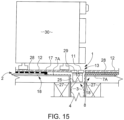
- a further embodiment is shown in Figure 15 using a channel 1 to provide a containment for an appliance 30.
- the channel is used to prevent spread of water or any other fluid that may emanate from the appliance 30, for example if the appliance fails for any reason, or the fluid supply to, or from, is compromised, in essence mitigation of any leaks.
- the channel is installed in a similar way to channels described earlier. It may be hidden underneath the appliance, or may be located in sight.
- the drainage channel 1 is located in a floor 2 of a room, for example a kitchen or laundry, under an appliance 30.
- the purpose of the drainage channel 1 is to prevent fluid that may leak from the appliance 30 from doing further damage to the floor 2 and any structures below, as well as spreading out along the floor to unprotected walls or similar.
- the need here is that typically areas where an appliance 30 may be do not always have waterproofing. Therefore fluid that finds its way from the appliance 30, can then spread through or along the floor 2. This poses a risk where for example the appliance is on a second story, and fluid otherwise may seep down and damage the building or rooms underneath that second story, or that may damage structures on the floor the appliance 30 is on, for example unprotected walls and similar.
- an aperture 13 is shown cut into a building floor 2.
- the building floor 2 is supported in the normal way for a building as shown using framing 27.
- the channel 1 is lowered into place in the aperture 13.
- the installer may add waterproofing, adhesive or sealant to the underside of the planar flanges 7 to seal against for example the sides or other surfaces of the aperture 13.
- Penetrative fasteners are then driven through the planar flanges 7 into the substrate below.
- the fasteners are driven into the building floor 2 (and framing 27 there under).
- framing 27 is provided at the periphery of the aperture to support the floor 2, and also to receive the penetrative fastenings from the planar flanges 7, however no framing is needed under the channel 4 itself.
- Penetrative fastenings 18 are also driven through the planar flanges 7A (not shown) on the sides of the channel 1.
- planar flanges and structural rigidity due to its elongate box form is sufficient to take all in use loading for the channel. Again predrilled holes, or indicated locations for them, may be present, as described above to show the required fastenings to securely hold the channel and prevent rupture of the waterproof envelope.
- waterproofing 17 extends at least in part down the sides 5 into the channel 4.
- a finishing 12 can then be applied for example tiles or similar to the floor.
- the finishing 12 on the floor extends up to the edge of the channel 4 as shown on either side.
- a grate with grate apertures 29 therein is then located in the channel 2.
- the grate has upstands 10 along its length that rest on the lowermost floor portion 25.
- the upstands can be adjusted in height, either by a threaded connection, or simply cutting them to length.
- the desired length is set so the upper surface 11 of the grate is substantially flush with the upper level of the floor finishing 12.
- the waste outlet 3 is connected to the waste aperture 8.
- fluid for example water from a dishwasher 30, can then flow over the floor finishing 12 into the channel 1 and then be taken away by the waste aperture 8 to the waste outlet 3 before it egresses over the floor 2 .
- the channel 1 does not need any framing made under it to support it.
Landscapes
- Health & Medical Sciences (AREA)
- Public Health (AREA)
- Engineering & Computer Science (AREA)
- Life Sciences & Earth Sciences (AREA)
- Hydrology & Water Resources (AREA)
- Water Supply & Treatment (AREA)
- Epidemiology (AREA)
- General Health & Medical Sciences (AREA)
- Environmental & Geological Engineering (AREA)
- Residential Or Office Buildings (AREA)
- Sink And Installation For Waste Water (AREA)
Claims (12)
- Canal de drainage (1) adapté pour recevoir un fluide (16) depuis un sol de bâtiment (2) et le drainer vers une sortie d'évacuation (3), ledit canal comprenant :(a) un canal ouvert vers le haut (4) présentant une partie de sol la plus basse (25), et des côtés (5) se trouvant autour de la partie de sol pour entourer et définir de manière fluide le canal ouvert vers le haut (4), sur une périphérie la plus haute (6) du canal ouvert vers le haut (4), un premier des côtés (5) présentant une bride sensiblement plane (7) s'étendant vers l'extérieur à partir de celui-ci, et sur la périphérie la plus haute (6), un deuxième des côtés (5) présentant une bride sensiblement plane (7) s'étendant vers l'extérieur ou vers le haut à partir de celui-ci, et(b) une ouverture d'évacuation (8) dans la partie de sol (25) pour permettre un drainage du fluide (16) depuis le canal ouvert vers le haut (4) vers la sortie d'évacuation (3) lorsqu'il est connecté de manière fluide à celle-ci,(C) une grille (9) supportée à partir de la partie de sol (25) par des montants (10) unitaires avec et s'étendant depuis une partie inférieure de la grille (9), les montants (10) étant ajustables en hauteur pour avoir une surface supérieure (11) de la grille (9) adaptée pour être sensiblement à une hauteur souhaitée par rapport à une surface supérieure (11) d'une finition (12) du sol de bâtiment (2),(d) des fixations pénétrantes (18),dans lequel le canal ouvert vers le haut (4) est adapté pour être situé sensiblement à l'intérieur d'une ouverture (13) dans le sol de bâtiment (2) et la ou les brides sensiblement planes (7) s'étendant vers l'extérieur est/sont adaptée(s) pour être fixée(s) à une surface de présentation supérieure (11) du sol (2), et, si elle est présente, la bride sensiblement plane (7) s'étendant vers le haut est fixée à une surface vers le haut de l'un de murs entourant au moins un canal (4), pour maintenir le canal de drainage (1) en place,dans lequel les brides planes (7) sont adaptées pour être fixées au sol (2) et aux murs du bâtiment à l'aide desdites fixations pénétrantes (18) à travers les brides planes (7) et dans le sol et les murs,dans lequel le canal de drainage (1) ne nécessite, en utilisation, aucun support par le bas, étant fixé en place uniquement par les brides planes (7),de sorte que le canal de drainage (1) est adapté pour être situé dans le sol du bâtiment (2) afin d'éliminer du fluide (16) à partir de celui-ci.
- Canal de drainage (1) selon la revendication 1, dans lequel la position des fixations pénétrantes (18) à travers les brides planes (7), les sols et les murs permet d'appliquer une imperméabilisation (17) et une finition de sol (12) au sol de bâtiment (2) sur les brides planes (7) et au moins en partie vers le bas dans le canal ouvert vers le haut (4).
- Canal de drainage (1) selon l'une quelconque des revendications 1 ou 2, dans lequel le canal de drainage (1) est formé à partir d'un matériau à paroi mince comprenantune tôle métallique pliée et formée, ouune matière plastique, moulée ou extrudée.
- Canal de drainage (1) selon l'une quelconque des revendications 1 à 3, dans lequel sur la périphérie la plus supérieure (6) du canal ouvert vers le haut (4), un troisième des côtés (5) adjacent au premier et/ou au deuxième des côtés (5) présente une bride sensiblement plane (7) s'étendant vers l'extérieur ou vers le haut à partir de celui-ci ; et/ou un quatrième des côtés (5) adjacent au premier et/ou au deuxième des côtés présente une bride sensiblement plane (7) s'étendant vers l'extérieur ou vers le haut à partir de celui-ci .
- Canal de drainage (1) selon la revendication 4, dans lequel : la bride sensiblement plane (7) du troisième des côtés (5) est jointe à la bride sensiblement plane (7) du premier et/ou du deuxième des côtés (5) ; et/ou la bride sensiblement plane (7) du quatrième des côtés (5) est jointe à la bride sensiblement plane (7) du premier et/ou du deuxième des côtés (5).
- Canal de drainage (1) selon l'une quelconque des revendications 1 à 5, dans lequel le premier des côtés (5) et le deuxième des côtés (5) sont parallèles et opposés l'un à l'autre.
- Procédé d'installation d'un canal de drainage (1) adapté pour recevoir un fluide (16) à partir d'un sol de bâtiment (2) et le drainer vers une sortie d'évacuation (3), comprenant les étapes consistant à,fournir un canal ouvert vers le haut (4) présentant une partie de sol la plus basse (25) et des côtés (5) se trouvant autour de la partie de sol pour entourer et définir de manière fluide le canal ouvert vers le haut (4), sur une périphérie la plus haute (6) du canal (4), un premier des côtés (5) présente une bride sensiblement plane (7) s'étendant vers l'extérieur à partir de celui-ci, et sur la périphérie la plus haute (6), un deuxième des côtés (5) présente une bride sensiblement plane (7) s'étendant vers l'extérieur ou vers le haut à partir de celui-ci, et une ouverture d'évacuation (8) dans la partie de sol pour permettre un drainage du fluide (16) depuis le canal ouvert vers le haut (4) vers la sortie d'évacuation (3) lorsqu'il est connecté de manière fluide à celle-ci,positionner le canal de drainage (4) dans une ouverture (13) dans le sol de bâtiment (2) et fixer les brides planes (7) à une surface de présentation supérieure du sol et/ou des murs environnants respectivement à l'aide de fixations pénétrantes (18) à travers les brides planes (7) et dans le sol et/ou les murs pour maintenir le canal de drainage (1) en place, et le canal de drainage (1) ne nécessitant aucun support par le bas, étant fixé en place uniquement par les brides planes (7),raccorder de manière fluide l'ouverture d'évacuation (8) à une sortie d'évacuation (3) du bâtiment,appliquer une imperméabilisation (17) au moins au sol de bâtiment (2) sur les brides planes (7) et au moins en partie vers le bas dans le canal ouvert vers le haut (4),poser une finition de sol de bâtiment (12) au moins sur une périphérie supérieure du canal ouvert vers le haut (4), etpositionner une grille (9) dans le canal ouvert vers le haut (4), la grille étant supportée depuis la partie de sol par des montants (10) unitaires avec et s'étendant depuis une partie inférieure de la grille (9),ajuster la hauteur de la grille (9) via une hauteur des montants (10) pour avoir une surface supérieure (11) de la grille (9) sensiblement à une hauteur souhaitée par rapport à une surface supérieure d'une finition (12) du sol de bâtiment (2),de telle sorte que ledit canal de drainage (1) est situé dans le sol de bâtiment (2) pour l'évacuation du fluide (16) depuis celui-ci vers la sortie des déchets (3).
- Procédé selon la revendication 7, dans lequel une finition (12) sur un mur environnant s'étend vers le bas au-delà de la périphérie du canal ouvert vers le haut (4).
- Procédé selon la revendication 7, dans lequel les côtés (5) adjacents à un mur présentent des brides sensiblement planes s'étendant vers le haut (7).
- Procédé selon la revendication 7, dans lequel ces côtés (5) adjacents à un sol de bâtiment (2) ont des brides sensiblement planes s'étendant vers l'extérieur (7).
- Procédé selon la revendication 7, dans lequel ledit canal de drainage (1) est situé dans un sol de bâtiment (2) dans un ou plusieurs des emplacements suivants :une douche (19) pour drainer du fluide (16) à partir de celle-ci,un sol d'une salle de bain, d'une buanderie ou d'une cuisine (20) ou similaire pour drainer les liquides déversés ou de nettoyage à partir de celui-ci,au niveau ou à proximité d'un seuil (21) entre une première zone (telle qu'une salle de bain, une buanderie ou une cuisine (20) et un couloir (22) ou une source potentielle similaire de fluide (16)) pour drainer le fluide (16) qui peut être déversé dans cette première zone afin d'empêcher ce fluide (16) de se déplacer dans une seconde zone.
- Procédé selon la revendication 7, dans lequel le canal de drainage (1) est dimensionné par rapport à une longueur de l'ouverture de sol de bâtiment (13).
Applications Claiming Priority (2)
| Application Number | Priority Date | Filing Date | Title |
|---|---|---|---|
| NZ71065615 | 2015-07-31 | ||
| PCT/NZ2016/050119 WO2017023178A1 (fr) | 2015-07-31 | 2016-07-29 | Améliorations apportées au drainage ou se rapportant à celui-ci |
Publications (3)
| Publication Number | Publication Date |
|---|---|
| EP3329057A1 EP3329057A1 (fr) | 2018-06-06 |
| EP3329057A4 EP3329057A4 (fr) | 2019-05-15 |
| EP3329057B1 true EP3329057B1 (fr) | 2023-10-25 |
Family
ID=57943353
Family Applications (1)
| Application Number | Title | Priority Date | Filing Date |
|---|---|---|---|
| EP16833393.8A Active EP3329057B1 (fr) | 2015-07-31 | 2016-07-29 | Améliorations apportées au drainage ou se rapportant à celui-ci |
Country Status (6)
| Country | Link |
|---|---|
| US (1) | US10513843B2 (fr) |
| EP (1) | EP3329057B1 (fr) |
| AU (2) | AU2016303926A1 (fr) |
| CA (1) | CA2994259C (fr) |
| ES (1) | ES2969741T3 (fr) |
| WO (1) | WO2017023178A1 (fr) |
Families Citing this family (6)
| Publication number | Priority date | Publication date | Assignee | Title |
|---|---|---|---|---|
| USD941442S1 (en) * | 2018-03-30 | 2022-01-18 | Jesani Limited | Surface mountable gutter |
| CN111560742B (zh) * | 2019-01-28 | 2023-05-12 | 合肥海尔滚筒洗衣机有限公司 | 一种排水管固定装置及洗涤设备 |
| DE202019107083U1 (de) | 2019-12-18 | 2021-03-19 | Schlüter-Systems Kg | Rahmen für einen Bodenablauf |
| DE202020100376U1 (de) | 2020-01-24 | 2021-04-27 | Schlüter-Systems Kg | Bodenablauf |
| US11655621B2 (en) * | 2021-07-12 | 2023-05-23 | Christopher Adam McLeod | Flat drain for showers |
| WO2025009979A1 (fr) * | 2023-07-05 | 2025-01-09 | Neptun Merverdi As | Unité de drainage et de ventilation combinée pour ouverture rugueuse |
Family Cites Families (17)
| Publication number | Priority date | Publication date | Assignee | Title |
|---|---|---|---|---|
| US1809549A (en) | 1927-08-22 | 1931-06-09 | Duncan Erskine | Drain hopper |
| US4410839A (en) | 1981-07-02 | 1983-10-18 | Hybrinetics, Inc. | Apparatus for controlling power consumption in lighting loads and the like |
| US5687068A (en) | 1995-12-22 | 1997-11-11 | Micro Weiss Electronics, Inc. | Power supply for in-line power controllers and two-terminal electronic thermostat employing same |
| NL1027175C1 (nl) | 2004-03-18 | 2005-09-20 | Jered Nijhof | Afvoergoot met rooster. |
| DE102004025874A1 (de) * | 2004-05-27 | 2005-12-22 | Dallmer Gmbh & Co. Kg | Ablaufrinne |
| US20080058712A1 (en) | 2006-08-31 | 2008-03-06 | Plahey Kulwinder S | Peritoneal dialysis machine with dual voltage heater circuit and method of operation |
| SE531099C2 (sv) * | 2007-08-08 | 2008-12-16 | Purus Ab | Avlopp |
| US8027572B2 (en) | 2008-02-22 | 2011-09-27 | Baxter International Inc. | Dialysis machine having multiple line voltage heater |
| CH699862B1 (de) * | 2008-11-10 | 2014-06-13 | Rivaplan Ag | Ablaufvorrichtung mit einer versenkt einbaubaren Ablaufrinne. |
| US8239974B2 (en) | 2008-12-29 | 2012-08-14 | Josef Erlebach | Elongated shower drain |
| US8474068B2 (en) | 2010-01-05 | 2013-07-02 | Noble Company | Trench shower drain |
| DE202010002011U1 (de) | 2010-02-05 | 2010-08-05 | Gassmann, Urs | Ablaufrinnen-System |
| DE202010002763U1 (de) | 2010-02-24 | 2011-07-27 | Schlüter-Systems Kg | Bodenablauf |
| EP2570559B1 (fr) * | 2011-09-14 | 2014-04-23 | Kessel AG | Rigole d'écoulement |
| CA2795862A1 (fr) * | 2011-11-18 | 2013-05-18 | Schluter Systems L.P. | Systemes de drain empilable et methodes associees |
| DE102013105544A1 (de) * | 2013-05-29 | 2014-12-04 | Wedi Gmbh | Wasserablaufvorrichtung für eine sanitäre Anlage, wie einen bodenebenen Duschplatz |
| US20140352815A1 (en) * | 2013-06-03 | 2014-12-04 | Durst Corporation, Inc. | Channel Drain With Integral Weep Path |
-
2016
- 2016-07-29 US US15/749,475 patent/US10513843B2/en active Active
- 2016-07-29 ES ES16833393T patent/ES2969741T3/es active Active
- 2016-07-29 WO PCT/NZ2016/050119 patent/WO2017023178A1/fr not_active Ceased
- 2016-07-29 AU AU2016303926A patent/AU2016303926A1/en not_active Abandoned
- 2016-07-29 CA CA2994259A patent/CA2994259C/fr active Active
- 2016-07-29 EP EP16833393.8A patent/EP3329057B1/fr active Active
-
2021
- 2021-09-01 AU AU2021225188A patent/AU2021225188B2/en active Active
Also Published As
| Publication number | Publication date |
|---|---|
| US10513843B2 (en) | 2019-12-24 |
| EP3329057A1 (fr) | 2018-06-06 |
| CA2994259C (fr) | 2023-10-24 |
| WO2017023178A1 (fr) | 2017-02-09 |
| CA2994259A1 (fr) | 2017-02-09 |
| AU2021225188A1 (en) | 2021-10-07 |
| ES2969741T3 (es) | 2024-05-22 |
| EP3329057A4 (fr) | 2019-05-15 |
| AU2016303926A1 (en) | 2018-03-22 |
| US20180238040A1 (en) | 2018-08-23 |
| AU2021225188B2 (en) | 2024-01-04 |
Similar Documents
| Publication | Publication Date | Title |
|---|---|---|
| AU2021225188B2 (en) | Improvements in, or related to, drainage | |
| US11825994B2 (en) | One-piece shower base | |
| US20090320204A1 (en) | Shower pan having no visible drainage means | |
| CA2904635C (fr) | Systeme de douche a entree a niveau | |
| IE20090882A1 (en) | Floor assembly for a bathroom | |
| US7621002B1 (en) | System and method for controlling, draining, removing, and disposing of liquids and light solids | |
| CN101379251A (zh) | 在成形卫生器具期间可直接得到的虹吸系统 | |
| KR101135564B1 (ko) | 조립식 욕실의 설치구조 | |
| KR100926825B1 (ko) | 다층건축물의 욕실구조 | |
| US8578522B1 (en) | System and method for controlling, draining, removing, and disposing of liquids and light solids | |
| AU2021107546A4 (en) | Shower base | |
| EP3540138B1 (fr) | Drain de sol | |
| US11655621B2 (en) | Flat drain for showers | |
| NO762966L (fr) | ||
| US20260049467A1 (en) | Methods and systems for flooring and substrate structures | |
| JP5598987B2 (ja) | 浴室ユニット構造 | |
| AU2023274182B1 (en) | Wet Room System | |
| EP1629755A2 (fr) | Installation de douche | |
| AU2016235034A1 (en) | Shower tray | |
| NZ722512B2 (en) | Improvements in, or related to, drainage | |
| NZ722512A (en) | Improvements in, or related to, drainage | |
| JP2002294787A (ja) | ユニットバス | |
| GB2459286A (en) | A stainless steel shower tray with a tile up-stand | |
| JP2021001501A (ja) | シャワールームユニット及び壁下アングル部材 | |
| NZ746966A (en) | Shower base |
Legal Events
| Date | Code | Title | Description |
|---|---|---|---|
| STAA | Information on the status of an ep patent application or granted ep patent |
Free format text: STATUS: THE INTERNATIONAL PUBLICATION HAS BEEN MADE |
|
| PUAI | Public reference made under article 153(3) epc to a published international application that has entered the european phase |
Free format text: ORIGINAL CODE: 0009012 |
|
| STAA | Information on the status of an ep patent application or granted ep patent |
Free format text: STATUS: REQUEST FOR EXAMINATION WAS MADE |
|
| 17P | Request for examination filed |
Effective date: 20180228 |
|
| AK | Designated contracting states |
Kind code of ref document: A1 Designated state(s): AL AT BE BG CH CY CZ DE DK EE ES FI FR GB GR HR HU IE IS IT LI LT LU LV MC MK MT NL NO PL PT RO RS SE SI SK SM TR |
|
| AX | Request for extension of the european patent |
Extension state: BA ME |
|
| DAV | Request for validation of the european patent (deleted) | ||
| DAX | Request for extension of the european patent (deleted) | ||
| A4 | Supplementary search report drawn up and despatched |
Effective date: 20190417 |
|
| RIC1 | Information provided on ipc code assigned before grant |
Ipc: E03F 5/04 20060101AFI20190411BHEP |
|
| STAA | Information on the status of an ep patent application or granted ep patent |
Free format text: STATUS: EXAMINATION IS IN PROGRESS |
|
| 17Q | First examination report despatched |
Effective date: 20210315 |
|
| GRAP | Despatch of communication of intention to grant a patent |
Free format text: ORIGINAL CODE: EPIDOSNIGR1 |
|
| STAA | Information on the status of an ep patent application or granted ep patent |
Free format text: STATUS: GRANT OF PATENT IS INTENDED |
|
| RIC1 | Information provided on ipc code assigned before grant |
Ipc: A47K 3/28 20060101ALI20221216BHEP Ipc: E03F 5/04 20060101AFI20221216BHEP |
|
| INTG | Intention to grant announced |
Effective date: 20230113 |
|
| GRAJ | Information related to disapproval of communication of intention to grant by the applicant or resumption of examination proceedings by the epo deleted |
Free format text: ORIGINAL CODE: EPIDOSDIGR1 |
|
| STAA | Information on the status of an ep patent application or granted ep patent |
Free format text: STATUS: EXAMINATION IS IN PROGRESS |
|
| GRAP | Despatch of communication of intention to grant a patent |
Free format text: ORIGINAL CODE: EPIDOSNIGR1 |
|
| STAA | Information on the status of an ep patent application or granted ep patent |
Free format text: STATUS: GRANT OF PATENT IS INTENDED |
|
| INTG | Intention to grant announced |
Effective date: 20230515 |
|
| GRAS | Grant fee paid |
Free format text: ORIGINAL CODE: EPIDOSNIGR3 |
|
| GRAA | (expected) grant |
Free format text: ORIGINAL CODE: 0009210 |
|
| STAA | Information on the status of an ep patent application or granted ep patent |
Free format text: STATUS: THE PATENT HAS BEEN GRANTED |
|
| AK | Designated contracting states |
Kind code of ref document: B1 Designated state(s): AL AT BE BG CH CY CZ DE DK EE ES FI FR GB GR HR HU IE IS IT LI LT LU LV MC MK MT NL NO PL PT RO RS SE SI SK SM TR |
|
| REG | Reference to a national code |
Ref country code: GB Ref legal event code: FG4D |
|
| REG | Reference to a national code |
Ref country code: CH Ref legal event code: EP |
|
| REG | Reference to a national code |
Ref country code: DE Ref legal event code: R096 Ref document number: 602016083723 Country of ref document: DE |
|
| REG | Reference to a national code |
Ref country code: IE Ref legal event code: FG4D |
|
| REG | Reference to a national code |
Ref country code: LT Ref legal event code: MG9D |
|
| REG | Reference to a national code |
Ref country code: NL Ref legal event code: MP Effective date: 20231025 |
|
| PG25 | Lapsed in a contracting state [announced via postgrant information from national office to epo] |
Ref country code: NL Free format text: LAPSE BECAUSE OF FAILURE TO SUBMIT A TRANSLATION OF THE DESCRIPTION OR TO PAY THE FEE WITHIN THE PRESCRIBED TIME-LIMIT Effective date: 20231025 |
|
| PG25 | Lapsed in a contracting state [announced via postgrant information from national office to epo] |
Ref country code: GR Free format text: LAPSE BECAUSE OF FAILURE TO SUBMIT A TRANSLATION OF THE DESCRIPTION OR TO PAY THE FEE WITHIN THE PRESCRIBED TIME-LIMIT Effective date: 20240126 |
|
| PG25 | Lapsed in a contracting state [announced via postgrant information from national office to epo] |
Ref country code: IS Free format text: LAPSE BECAUSE OF FAILURE TO SUBMIT A TRANSLATION OF THE DESCRIPTION OR TO PAY THE FEE WITHIN THE PRESCRIBED TIME-LIMIT Effective date: 20240225 |
|
| PG25 | Lapsed in a contracting state [announced via postgrant information from national office to epo] |
Ref country code: LT Free format text: LAPSE BECAUSE OF FAILURE TO SUBMIT A TRANSLATION OF THE DESCRIPTION OR TO PAY THE FEE WITHIN THE PRESCRIBED TIME-LIMIT Effective date: 20231025 |
|
| PG25 | Lapsed in a contracting state [announced via postgrant information from national office to epo] |
Ref country code: LT Free format text: LAPSE BECAUSE OF FAILURE TO SUBMIT A TRANSLATION OF THE DESCRIPTION OR TO PAY THE FEE WITHIN THE PRESCRIBED TIME-LIMIT Effective date: 20231025 Ref country code: IS Free format text: LAPSE BECAUSE OF FAILURE TO SUBMIT A TRANSLATION OF THE DESCRIPTION OR TO PAY THE FEE WITHIN THE PRESCRIBED TIME-LIMIT Effective date: 20240225 Ref country code: GR Free format text: LAPSE BECAUSE OF FAILURE TO SUBMIT A TRANSLATION OF THE DESCRIPTION OR TO PAY THE FEE WITHIN THE PRESCRIBED TIME-LIMIT Effective date: 20240126 Ref country code: BG Free format text: LAPSE BECAUSE OF FAILURE TO SUBMIT A TRANSLATION OF THE DESCRIPTION OR TO PAY THE FEE WITHIN THE PRESCRIBED TIME-LIMIT Effective date: 20240125 Ref country code: PT Free format text: LAPSE BECAUSE OF FAILURE TO SUBMIT A TRANSLATION OF THE DESCRIPTION OR TO PAY THE FEE WITHIN THE PRESCRIBED TIME-LIMIT Effective date: 20240226 |
|
| REG | Reference to a national code |
Ref country code: ES Ref legal event code: FG2A Ref document number: 2969741 Country of ref document: ES Kind code of ref document: T3 Effective date: 20240522 |
|
| PG25 | Lapsed in a contracting state [announced via postgrant information from national office to epo] |
Ref country code: SE Free format text: LAPSE BECAUSE OF FAILURE TO SUBMIT A TRANSLATION OF THE DESCRIPTION OR TO PAY THE FEE WITHIN THE PRESCRIBED TIME-LIMIT Effective date: 20231025 Ref country code: RS Free format text: LAPSE BECAUSE OF FAILURE TO SUBMIT A TRANSLATION OF THE DESCRIPTION OR TO PAY THE FEE WITHIN THE PRESCRIBED TIME-LIMIT Effective date: 20231025 Ref country code: PL Free format text: LAPSE BECAUSE OF FAILURE TO SUBMIT A TRANSLATION OF THE DESCRIPTION OR TO PAY THE FEE WITHIN THE PRESCRIBED TIME-LIMIT Effective date: 20231025 Ref country code: NO Free format text: LAPSE BECAUSE OF FAILURE TO SUBMIT A TRANSLATION OF THE DESCRIPTION OR TO PAY THE FEE WITHIN THE PRESCRIBED TIME-LIMIT Effective date: 20240125 Ref country code: LV Free format text: LAPSE BECAUSE OF FAILURE TO SUBMIT A TRANSLATION OF THE DESCRIPTION OR TO PAY THE FEE WITHIN THE PRESCRIBED TIME-LIMIT Effective date: 20231025 Ref country code: HR Free format text: LAPSE BECAUSE OF FAILURE TO SUBMIT A TRANSLATION OF THE DESCRIPTION OR TO PAY THE FEE WITHIN THE PRESCRIBED TIME-LIMIT Effective date: 20231025 |
|
| PG25 | Lapsed in a contracting state [announced via postgrant information from national office to epo] |
Ref country code: DK Free format text: LAPSE BECAUSE OF FAILURE TO SUBMIT A TRANSLATION OF THE DESCRIPTION OR TO PAY THE FEE WITHIN THE PRESCRIBED TIME-LIMIT Effective date: 20231025 |
|
| PG25 | Lapsed in a contracting state [announced via postgrant information from national office to epo] |
Ref country code: CZ Free format text: LAPSE BECAUSE OF FAILURE TO SUBMIT A TRANSLATION OF THE DESCRIPTION OR TO PAY THE FEE WITHIN THE PRESCRIBED TIME-LIMIT Effective date: 20231025 |
|
| REG | Reference to a national code |
Ref country code: DE Ref legal event code: R097 Ref document number: 602016083723 Country of ref document: DE |
|
| PG25 | Lapsed in a contracting state [announced via postgrant information from national office to epo] |
Ref country code: SK Free format text: LAPSE BECAUSE OF FAILURE TO SUBMIT A TRANSLATION OF THE DESCRIPTION OR TO PAY THE FEE WITHIN THE PRESCRIBED TIME-LIMIT Effective date: 20231025 |
|
| PG25 | Lapsed in a contracting state [announced via postgrant information from national office to epo] |
Ref country code: SM Free format text: LAPSE BECAUSE OF FAILURE TO SUBMIT A TRANSLATION OF THE DESCRIPTION OR TO PAY THE FEE WITHIN THE PRESCRIBED TIME-LIMIT Effective date: 20231025 Ref country code: SK Free format text: LAPSE BECAUSE OF FAILURE TO SUBMIT A TRANSLATION OF THE DESCRIPTION OR TO PAY THE FEE WITHIN THE PRESCRIBED TIME-LIMIT Effective date: 20231025 Ref country code: RO Free format text: LAPSE BECAUSE OF FAILURE TO SUBMIT A TRANSLATION OF THE DESCRIPTION OR TO PAY THE FEE WITHIN THE PRESCRIBED TIME-LIMIT Effective date: 20231025 Ref country code: EE Free format text: LAPSE BECAUSE OF FAILURE TO SUBMIT A TRANSLATION OF THE DESCRIPTION OR TO PAY THE FEE WITHIN THE PRESCRIBED TIME-LIMIT Effective date: 20231025 Ref country code: DK Free format text: LAPSE BECAUSE OF FAILURE TO SUBMIT A TRANSLATION OF THE DESCRIPTION OR TO PAY THE FEE WITHIN THE PRESCRIBED TIME-LIMIT Effective date: 20231025 Ref country code: CZ Free format text: LAPSE BECAUSE OF FAILURE TO SUBMIT A TRANSLATION OF THE DESCRIPTION OR TO PAY THE FEE WITHIN THE PRESCRIBED TIME-LIMIT Effective date: 20231025 |
|
| PLBE | No opposition filed within time limit |
Free format text: ORIGINAL CODE: 0009261 |
|
| STAA | Information on the status of an ep patent application or granted ep patent |
Free format text: STATUS: NO OPPOSITION FILED WITHIN TIME LIMIT |
|
| 26N | No opposition filed |
Effective date: 20240726 |
|
| PG25 | Lapsed in a contracting state [announced via postgrant information from national office to epo] |
Ref country code: SI Free format text: LAPSE BECAUSE OF FAILURE TO SUBMIT A TRANSLATION OF THE DESCRIPTION OR TO PAY THE FEE WITHIN THE PRESCRIBED TIME-LIMIT Effective date: 20231025 |
|
| PG25 | Lapsed in a contracting state [announced via postgrant information from national office to epo] |
Ref country code: SI Free format text: LAPSE BECAUSE OF FAILURE TO SUBMIT A TRANSLATION OF THE DESCRIPTION OR TO PAY THE FEE WITHIN THE PRESCRIBED TIME-LIMIT Effective date: 20231025 |
|
| PG25 | Lapsed in a contracting state [announced via postgrant information from national office to epo] |
Ref country code: MC Free format text: LAPSE BECAUSE OF FAILURE TO SUBMIT A TRANSLATION OF THE DESCRIPTION OR TO PAY THE FEE WITHIN THE PRESCRIBED TIME-LIMIT Effective date: 20231025 |
|
| REG | Reference to a national code |
Ref country code: CH Ref legal event code: PL |
|
| PG25 | Lapsed in a contracting state [announced via postgrant information from national office to epo] |
Ref country code: LU Free format text: LAPSE BECAUSE OF NON-PAYMENT OF DUE FEES Effective date: 20240729 |
|
| PG25 | Lapsed in a contracting state [announced via postgrant information from national office to epo] |
Ref country code: LU Free format text: LAPSE BECAUSE OF NON-PAYMENT OF DUE FEES Effective date: 20240729 |
|
| PG25 | Lapsed in a contracting state [announced via postgrant information from national office to epo] |
Ref country code: CH Free format text: LAPSE BECAUSE OF NON-PAYMENT OF DUE FEES Effective date: 20240731 Ref country code: BE Free format text: LAPSE BECAUSE OF NON-PAYMENT OF DUE FEES Effective date: 20240731 |
|
| REG | Reference to a national code |
Ref country code: BE Ref legal event code: MM Effective date: 20240731 |
|
| PG25 | Lapsed in a contracting state [announced via postgrant information from national office to epo] |
Ref country code: IE Free format text: LAPSE BECAUSE OF NON-PAYMENT OF DUE FEES Effective date: 20240729 |
|
| PG25 | Lapsed in a contracting state [announced via postgrant information from national office to epo] |
Ref country code: FI Free format text: LAPSE BECAUSE OF FAILURE TO SUBMIT A TRANSLATION OF THE DESCRIPTION OR TO PAY THE FEE WITHIN THE PRESCRIBED TIME-LIMIT Effective date: 20231025 |
|
| PGFP | Annual fee paid to national office [announced via postgrant information from national office to epo] |
Ref country code: ES Payment date: 20250812 Year of fee payment: 10 |
|
| PGFP | Annual fee paid to national office [announced via postgrant information from national office to epo] |
Ref country code: DE Payment date: 20250731 Year of fee payment: 10 |
|
| PGFP | Annual fee paid to national office [announced via postgrant information from national office to epo] |
Ref country code: IT Payment date: 20250730 Year of fee payment: 10 |
|
| PGFP | Annual fee paid to national office [announced via postgrant information from national office to epo] |
Ref country code: GB Payment date: 20250731 Year of fee payment: 10 |
|
| PGFP | Annual fee paid to national office [announced via postgrant information from national office to epo] |
Ref country code: FR Payment date: 20250730 Year of fee payment: 10 Ref country code: AT Payment date: 20250731 Year of fee payment: 10 |
|
| PG25 | Lapsed in a contracting state [announced via postgrant information from national office to epo] |
Ref country code: CY Free format text: LAPSE BECAUSE OF FAILURE TO SUBMIT A TRANSLATION OF THE DESCRIPTION OR TO PAY THE FEE WITHIN THE PRESCRIBED TIME-LIMIT; INVALID AB INITIO Effective date: 20160729 |
|
| PG25 | Lapsed in a contracting state [announced via postgrant information from national office to epo] |
Ref country code: HU Free format text: LAPSE BECAUSE OF FAILURE TO SUBMIT A TRANSLATION OF THE DESCRIPTION OR TO PAY THE FEE WITHIN THE PRESCRIBED TIME-LIMIT; INVALID AB INITIO Effective date: 20160729 |
|
| REG | Reference to a national code |
Ref country code: AT Ref legal event code: UEP Ref document number: 1624790 Country of ref document: AT Kind code of ref document: T Effective date: 20231025 |