EP3329216B1 - Détermination d'une information de disposition pour un véhicule - Google Patents
Détermination d'une information de disposition pour un véhicule Download PDFInfo
- Publication number
- EP3329216B1 EP3329216B1 EP16733965.4A EP16733965A EP3329216B1 EP 3329216 B1 EP3329216 B1 EP 3329216B1 EP 16733965 A EP16733965 A EP 16733965A EP 3329216 B1 EP3329216 B1 EP 3329216B1
- Authority
- EP
- European Patent Office
- Prior art keywords
- arrangement
- lane
- vehicle
- information
- lanes
- Prior art date
- Legal status (The legal status is an assumption and is not a legal conclusion. Google has not performed a legal analysis and makes no representation as to the accuracy of the status listed.)
- Active
Links
Images


Classifications
-
- G—PHYSICS
- G01—MEASURING; TESTING
- G01C—MEASURING DISTANCES, LEVELS OR BEARINGS; SURVEYING; NAVIGATION; GYROSCOPIC INSTRUMENTS; PHOTOGRAMMETRY OR VIDEOGRAMMETRY
- G01C21/00—Navigation; Navigational instruments not provided for in groups G01C1/00 - G01C19/00
- G01C21/26—Navigation; Navigational instruments not provided for in groups G01C1/00 - G01C19/00 specially adapted for navigation in a road network
- G01C21/28—Navigation; Navigational instruments not provided for in groups G01C1/00 - G01C19/00 specially adapted for navigation in a road network with correlation of data from several navigational instruments
- G01C21/30—Map- or contour-matching
-
- G—PHYSICS
- G06—COMPUTING OR CALCULATING; COUNTING
- G06V—IMAGE OR VIDEO RECOGNITION OR UNDERSTANDING
- G06V20/00—Scenes; Scene-specific elements
- G06V20/50—Context or environment of the image
- G06V20/56—Context or environment of the image exterior to a vehicle by using sensors mounted on the vehicle
- G06V20/588—Recognition of the road, e.g. of lane markings; Recognition of the vehicle driving pattern in relation to the road
-
- B—PERFORMING OPERATIONS; TRANSPORTING
- B60—VEHICLES IN GENERAL
- B60W—CONJOINT CONTROL OF VEHICLE SUB-UNITS OF DIFFERENT TYPE OR DIFFERENT FUNCTION; CONTROL SYSTEMS SPECIALLY ADAPTED FOR HYBRID VEHICLES; ROAD VEHICLE DRIVE CONTROL SYSTEMS FOR PURPOSES NOT RELATED TO THE CONTROL OF A PARTICULAR SUB-UNIT
- B60W60/00—Drive control systems specially adapted for autonomous road vehicles
- B60W60/001—Planning or execution of driving tasks
-
- G—PHYSICS
- G01—MEASURING; TESTING
- G01C—MEASURING DISTANCES, LEVELS OR BEARINGS; SURVEYING; NAVIGATION; GYROSCOPIC INSTRUMENTS; PHOTOGRAMMETRY OR VIDEOGRAMMETRY
- G01C21/00—Navigation; Navigational instruments not provided for in groups G01C1/00 - G01C19/00
- G01C21/26—Navigation; Navigational instruments not provided for in groups G01C1/00 - G01C19/00 specially adapted for navigation in a road network
- G01C21/34—Route searching; Route guidance
- G01C21/36—Input/output arrangements for on-board computers
- G01C21/3602—Input other than that of destination using image analysis, e.g. detection of road signs, lanes, buildings, real preceding vehicles using a camera
-
- B—PERFORMING OPERATIONS; TRANSPORTING
- B60—VEHICLES IN GENERAL
- B60W—CONJOINT CONTROL OF VEHICLE SUB-UNITS OF DIFFERENT TYPE OR DIFFERENT FUNCTION; CONTROL SYSTEMS SPECIALLY ADAPTED FOR HYBRID VEHICLES; ROAD VEHICLE DRIVE CONTROL SYSTEMS FOR PURPOSES NOT RELATED TO THE CONTROL OF A PARTICULAR SUB-UNIT
- B60W2420/00—Indexing codes relating to the type of sensors based on the principle of their operation
- B60W2420/40—Photo, light or radio wave sensitive means, e.g. infrared sensors
- B60W2420/403—Image sensing, e.g. optical camera
-
- B—PERFORMING OPERATIONS; TRANSPORTING
- B60—VEHICLES IN GENERAL
- B60W—CONJOINT CONTROL OF VEHICLE SUB-UNITS OF DIFFERENT TYPE OR DIFFERENT FUNCTION; CONTROL SYSTEMS SPECIALLY ADAPTED FOR HYBRID VEHICLES; ROAD VEHICLE DRIVE CONTROL SYSTEMS FOR PURPOSES NOT RELATED TO THE CONTROL OF A PARTICULAR SUB-UNIT
- B60W2552/00—Input parameters relating to infrastructure
- B60W2552/10—Number of lanes
-
- B—PERFORMING OPERATIONS; TRANSPORTING
- B60—VEHICLES IN GENERAL
- B60W—CONJOINT CONTROL OF VEHICLE SUB-UNITS OF DIFFERENT TYPE OR DIFFERENT FUNCTION; CONTROL SYSTEMS SPECIALLY ADAPTED FOR HYBRID VEHICLES; ROAD VEHICLE DRIVE CONTROL SYSTEMS FOR PURPOSES NOT RELATED TO THE CONTROL OF A PARTICULAR SUB-UNIT
- B60W2552/00—Input parameters relating to infrastructure
- B60W2552/53—Road markings, e.g. lane marker or crosswalk
Definitions
- the present invention relates to a method for determining vehicle layout information, in particular determining a vehicle layout taking into account lane-specific map information while simultaneously improving an assumption or hypothesis regarding the layout of the lanes.
- the present invention can be used in particular in conjunction with driver assistance systems that enable or support automatic guidance of the vehicle in a longitudinal and/or transverse direction.
- the DE 10 2011 120 497 A1 A system for precise vehicle positioning within a lane.
- the method is carried out by a vehicle having an on-board computer, vehicle sensors, a satellite positioning unit, and a database with a lane-level map to determine a new position of the vehicle using map matching.
- the method includes receiving new data from at least one of the vehicle sensors. and measured values are collected from the vehicle sensors.
- the on-board computer calculates the propagation of the vehicle's position with respect to successive points in time. Furthermore, the on-board computer performs a curve fitting process in which, for example, GPS coordinates of the vehicle are obtained and the vehicle's location within the map is identified at the lane level.
- the on-board computer executes a tracking program which includes using a probability distribution to update the vehicle's position with respect to data particles and, based on the data particles, executes a particle filtering program to calculate the new vehicle position.
- a tracking program which includes using a probability distribution to update the vehicle's position with respect to data particles and, based on the data particles, executes a particle filtering program to calculate the new vehicle position.
- an observation model is updated.
- data is read from the map at the lane level, which identifies at least one registered lane line near the vehicle, and a position of the lane line with respect to a reference system of the host vehicle is calculated.
- the detected and recorded lane lines and boundaries are aligned, and using the aligned data, an observation probability distribution is calculated with respect to image recognition data from a camera of the vehicle sensors.
- the lane lines obtained from a map coordinate system at the lane level are projected onto the vehicle's reference system, and the detected and recorded lane lines and boundaries are aligned, using a Euclidean-type distance analysis as the distance analysis.
- the DE 10 2010 033 729 B4 relates to a method for determining the position of a vehicle on a roadway.
- the position of the vehicle is determined with a first accuracy based on outputs from a satellite signal sensor.
- Data on a first vehicle environment for the position determined with the first accuracy are obtained from a digital map.
- data on lane markings in a second vehicle environment are obtained using a line detection sensor.
- Data on the vehicle's own movement are obtained using a vehicle dynamics sensor, and data on objects in a third vehicle environment are obtained using an environment sensor.
- the position of the vehicle with at least lane-specific accuracy on the roadway is determined by combining the data on the first vehicle environment from the digital map and the data on the lane markings in the second vehicle environment with the data on the vehicle's own movement or the data on objects in the third vehicle environment, depending on the road situation.
- the object of the present invention is therefore to enable a more reliable determination of the position and orientation of the vehicle relative to the actual roadway.
- This object is achieved according to the present invention by a method for determining location information for a vehicle according to claim 1, and a location determination device according to claim 10.
- the dependent claims define preferred and advantageous embodiments of the invention.
- a method for determining location information for a vehicle is provided.
- location information refers to a position of the vehicle and an orientation of the vehicle relative to a stationary coordinate system, such as a world-spanning global coordinate system such as the World Geodetic System (abbreviated WGS).
- WGS World Geodetic System
- the stationary coordinate system can also comprise any other coordinate system external to the vehicle, such as a country-specific coordinate system.
- the term "arrangement information" is also referred to as "pose” and comprises at least a two-dimensional position in the stationary coordinate system as well as an orientation of the vehicle with respect to the stationary coordinate system.
- a local lane arrangement in an environment of the vehicle is detected using sensors of the vehicle.
- the lane arrangement can be detected, for example, using cameras of the vehicle.
- the local lane arrangement indicates an arrangement of lanes in the environment of the vehicle with respect to the vehicle.
- a first lane arrangement is determined for the vehicle.
- the first lane arrangement specifies an arrangement of lanes in the vehicle's surroundings with respect to the stationary coordinate system.
- a (first) lane arrangement with respect to the stationary coordinate system is determined from the local lane arrangement, which results from the vehicle's view or perception.
- a second lane arrangement is determined for the vehicle's current surroundings with respect to the stationary coordinate system and the previously determined arrangement information for the vehicle.
- similarity information is determined, and the previously determined arrangement information for the vehicle is updated depending on the similarity information and odometry data of the vehicle. For example, shifts may be necessary to map the first lane arrangement to the second lane arrangement. Based on these shifts, the arrangement information or pose for the vehicle can be updated.
- a previously determined lane arrangement hypothesis is further updated depending on the similarity information.
- the lane arrangement hypothesis specifies a hypothesis for an arrangement of lanes in the surroundings of the vehicle with respect to the stationary coordinate system.
- both the arrangement information i.e., a pose estimate for the vehicle, and a lane arrangement hypothesis can be jointly updated and optimized.
- the vehicle arrangement information comprises parameters of a multidimensional normal distribution for the position and orientation of the vehicle.
- the position can comprise a two-dimensional normal distribution for the position of the vehicle in a Cartesian coordinate system
- the orientation can comprise a further normal distribution for a rotation angle of the vehicle relative to a predetermined orientation of the coordinate system.
- Coordinates of the lane arrangement hypothesis for example, points along a lane center, can also be represented as multidimensional normal distributions.
- the parameters of each of these normal distributions can include, for example, an expected value and a variance.
- a lane of a lane arrangement is represented by a point list representing the lane center.
- Each point in the point list has parameters of a multidimensional normal distribution for a position relative to the stationary coordinate system.
- Map material containing point lists marking the center of lanes is commonly available and can therefore be advantageously used in the method.
- uncertainties in the map material can be taken into account.
- the coordinates specified by the map material in each dimension can be used as the expected values of the normal distribution in the respective dimension.
- a standard deviation of the normal distribution in the respective dimension can be selected, for example, based on the map accuracy.
- the previously determined arrangement information for the vehicle is updated depending on the vehicle's odometry data.
- the vehicle's odometry data can include, for example, information from wheel sensors, steering angle sensors, or acceleration sensors of the vehicle.
- a relative change in the vehicle's arrangement with respect to a previous position can be determined.
- current arrangement information can be determined by incorporating the odometry data, whereby inaccuracies in the previously determined arrangement information and measurement inaccuracies of the odometry data can be taken into account in the form of normal distributions. This allows the vehicle's odometry data, including its possible errors, to be taken into account when updating the arrangement information for the vehicle.
- a stationary position of the vehicle is detected.
- the stationary position indicates a position of the vehicle with respect to the stationary coordinate system.
- the stationary coordinate system can, for example, be a global coordinate system, wherein the stationary position is detected, for example, using a satellite positioning system.
- the previously determined arrangement information for the vehicle is updated depending on the detected stationary position of the vehicle. Since the detected stationary position of the vehicle may have a measurement inaccuracy, the stationary position of the vehicle in the form of a multidimensional normal distribution can be taken into account when updating the previously determined arrangement information.
- the normal distribution-based representation approach for the vehicle's layout information and the additional information for updating the vehicle's layout information, such as odometry data, map information, camera-based environmental information, and satellite-based positioning information
- this information which is subject to measurement errors, including its potential errors, can be easily processed to update the vehicle's layout information.
- the normal distribution-based representation approach allows the layout information to be updated within a few milliseconds on a conventional computing system, such as a microprocessor controller in a vehicle, and is thus suitable for real-time computing in the vehicle.
- a repetition rate for repeatedly performing the method can, for example, be in the range of 25 to 400 repetitions per second.
- lane information for the first lane arrangement is determined using the vehicle's sensors.
- the lane information includes, for example, lane marking types, stop line positions, or traffic sign positions.
- Lane marking types can include, for example, a solid lane marking, a broken lane marking, a double solid line, and the like.
- the lane information for the first lane arrangement is compared with map material-based lane information for the second lane arrangement. This can improve the assignment of the lanes detected by the vehicle's sensors to lanes from the map material.
- the first lane arrangement comprises an arrangement of at least two lanes and, alternatively or additionally, the second lane arrangement comprises an arrangement of at least two lanes.
- a plurality of pair similarity information items is determined. Each of the plurality of pair similarity information items is determined as a function of a geometric similarity of a respective pair of two lanes. Each respective pair of two lanes comprises a lane from the first lane arrangement and a lane from the second lane arrangement. In other words, a pair similarity information item is determined for each combination of a lane from the first lane arrangement and a lane from the second lane arrangement.
- first lane arrangement comprises two lanes and the second lane arrangement also comprises two lanes
- four pieces of pair similarity information are determined: a first piece of similarity information for a similarity between a first lane of the first lane arrangement and a first lane of the second lane arrangement, a second piece of pair similarity information for a geometric similarity between the first lane of the first lane arrangement and the second lane of the second lane arrangement, a third piece of pair similarity information for a geometric similarity between a second lane of the first lane arrangement and the first lane of the second lane arrangement, and a fourth piece of pair similarity information for a geometric similarity between the second lane of the first lane arrangement and the second lane of the second lane arrangement.
- the arrangement information for the vehicle and the lane arrangement hypothesis can be updated even in complex scenarios, such as intersections or exits.
- the previously determined arrangement information for the vehicle can be updated depending on the similarity information by determining a respective weighted update information for each pair similarity information of the plurality of pair similarity information items depending on the respective pair similarity information.
- the weighted update information includes arrangement information for the vehicle under the assumption that the lanes of the respective pair relate to the same actual lane.
- the weight of the weighted update information indicates a probability that the lanes of the respective pair relate to the same actual lane.
- the previously determined arrangement information is updated depending on the weighted update information, for example, by multiplying an update based on pair similarity information by the weight.
- the arrangement information of the vehicle can, in particular, each comprise parameters of a multidimensional normal distribution for the position and orientation of the vehicle.
- the normal distribution of the alignment information is multiplied by the normal distributions of the update information. This allows the vehicle alignment information to be easily updated even in complex situations and scenarios, such as multi-lane roadways, intersections, and exits.
- the first lane arrangement indicates an arrangement of lanes in the vehicle's surroundings with respect to the stationary coordinate system.
- the processing device converts the local lane arrangement into a corresponding global lane arrangement, taking into account the most recently determined arrangement information or pose for the vehicle.
- the processing device is further capable of determining a second lane arrangement depending on predetermined map material and the previously determined arrangement information for the vehicle.
- the second lane arrangement indicates an arrangement of lanes in the surroundings of the vehicle with respect to the stationary coordinate system.
- the second lane arrangement can be determined, for example, from the predetermined map material using the previously determined arrangement information for the vehicle.
- the processing device determines similarity information depending on a geometric similarity between the first lane arrangement and the second lane arrangement. This similarity information and odometry data of the vehicle are used to update the previously determined arrangement information for the vehicle.
- the arrangement determination device suitable for carrying out the method described above or one of its embodiments and therefore also includes the advantages described in connection with the method.
- the present invention further relates to a vehicle comprising the previously described arrangement determination device and a driver assistance system.
- the driver assistance system provides an automatic driving function for the vehicle, for example, automatic longitudinal and lateral control of the vehicle.
- the driver assistance system is coupled to the arrangement determination device, and the automatic driving function is executed based on the updated arrangement information from the arrangement determination device.
- the vehicle therefore also includes the advantages previously described in connection with the method and its embodiments.
- a previously determined lane arrangement hypothesis can be updated depending on the similarity information.
- the lane arrangement hypothesis specifies a hypothesis for an arrangement of lanes in the surroundings of the vehicle with respect to the stationary coordinate system.
- the updated lane arrangement hypothesis can be taken into account by the driver assistance system when executing the automatic driving function, for example, by relating the arrangement information or pose of the vehicle to the updated lane arrangement hypothesis and, in particular, by controlling lateral control of the vehicle on this basis.
- Fig. 1 shows a vehicle 10 with a layout determination device 11 and a driver assistance system 12.
- the driver assistance system 12 is capable of performing an automatic driving function for the vehicle 10. To do this, the driver assistance system 12 requires information about the lane the vehicle 10 is currently in and the current position of the vehicle 10 in relation to the lane.
- the layout determination device 11 provides this information via a connection 13.
- the layout determination device 11 comprises a sensor 14, for example one or more cameras, for detecting a local lane layout in an environment of the vehicle 10.
- the local lane layout can be calculated, for example, by a processing device 15 of the layout determination device 11 using suitable image processing, taking into account the arrangement of the camera 14 on the vehicle 10.
- the processing device 15 is further equipped with a global positioning system, which, for example, receives signals from satellites via an antenna 16 and calculates a global position of the vehicle 10 therefrom.
- the processing device 15 can further be connected via a vehicle bus 17 to further components of the vehicle 10, which provide odometry data of the vehicle.
- the processing device 15 can receive information from a wheel sensor 18 to determine a movement of the vehicle 10.
- further wheel sensors, acceleration sensors, or a steering angle sensor can be coupled to the processing device 15 to calculate odometry data of the vehicle 10.
- the driver assistance system 12 requires comprehensive knowledge of the current surroundings of the vehicle 10 as well as the position and orientation of the vehicle 10 in the current surroundings.
- An important aspect of this surroundings is the road infrastructure in the immediate vicinity of the vehicle 10, since the automatic behavior of the vehicle, for example, longitudinal and lateral control of the vehicle, must be planned in this area.
- the arrangement determination device 11 uses various types of information sources: prior knowledge from lane-accurate road maps in combination with global positioning via, for example, GPS, as well as sensor-based perception of the lanes via, for example, the camera 14.
- the most probable pose i.e., the position and orientation of the vehicle 10
- the arrangement device 11 Fig. 2 procedures described in detail.
- the arrangement determination device 11 uses a global position measurement, a lane-accurate digital road map and a so-called perception method which generates lane hypotheses from sensor data, in particular from the camera 14.
- Global position measurement can be carried out, for example, using a global positioning system such as GPS or Galileo.
- the measurement method determines a two-dimensional position, for example in a global reference system of geodesy, such as the World Geodetic System, abbreviated WGS.
- WGS World Geodetic System
- the two-dimensional position can be determined in any other stationary, i.e. non-vehicle-related, reference system.
- a measurement variance is or is assigned to the measurement method of global position measurement.
- a global orientation of the vehicle including a corresponding measurement variance, is also determined, for example using a compass.
- the two-dimensional position in conjunction with the orientation of the vehicle will hereinafter be referred to as arrangement information for the vehicle or the pose of the vehicle.
- the lane-accurate digital road map provides information for individual lanes.
- the lanes are defined as a list of points, each with a position including the modeling variance.
- the point list represents the lane center, and all points on the connecting lines are interpreted as linear interpolations of the neighboring modeled points. Furthermore, it can be expanded with additional features, such as the types of lane markings on the right and left lane edges or the positions of stop lines and traffic signs.
- the perception process generates lane hypotheses from sensor data from the vehicle's sensors.
- the sensors used and the methods for determining the lane hypotheses are irrelevant. However, in particular, cameras on the vehicle can be used, for example, and the lane hypotheses can be determined based on digital image processing.
- the result of the process is the lane hypotheses as point lists, each representing the lane center. Since the perception process is carried out using vehicle sensors, the points in the point lists are located in a coordinate system aligned with the vehicle, a so-called local reference system, known as "ego-local coordinates." The coordinates of the points also exhibit measurement variance.
- the same additional features as in the map can be extracted from the sensor data, such as lane marking types, stop lines, and traffic sign positions.
- odometry data of the vehicle are used as input data for determining the arrangement information, which describe the vehicle's own movement continuously or between certain points in time, so-called time steps.
- the method 20 shown comprises method steps 21 to 28.
- an initialization takes place. For example, pose hypotheses are determined at a current GPS position, map material is loaded, and a current lane hypothesis is determined from the map material for the current GPS position.
- the subsequent steps 22 to 28 are executed cyclically, with a cycle lasting, for example, a few milliseconds, for example, 3 to 40 ms.
- the cycle duration can, for example, correspond to a duration required for acquiring sensor data from, for example, the camera 14, the wheel sensors 18, and the global positioning system.
- the pose and lane hypotheses are represented as multidimensional normal distributions (Gaussian mixture distribution).
- information for updating the pose and lane hypotheses such as results from the global position measurement, the perception method, and the odometry data, as well as information from the digital road map, are represented as corresponding multidimensional normal distributions. Updates can then be realized, for example, by multiplying all components of these distributions.
- the pose hypothesis from the last time step or from the initialization is updated using the odometry data and thus transferred to the current processing time.
- the pose hypothesis is updated using the global position measurement.
- step 24 the local lane arrangement is detected using the perception method described above, and in step 25, these locally detected lanes are transferred to the global or stationary coordinate system using the current pose hypothesis.
- a first lane arrangement is available, which was formed based on the locally recorded lanes.
- a second lane arrangement is determined from the map material.
- the sensor-based lanes from the first lane arrangement are then compared pairwise with the map-based lanes from the second lane arrangement (step 26).
- a geometric similarity of each lane pair is determined, including for systematic shifts of the lanes relative to one another.
- the similarity value can be enriched and improved by comparing additional information, such as the lane marking types or stop line and traffic sign positions.
- a respective weighted pose update is created.
- the pose results from the various shifts relative to one another, and the weight results from the similarities between the lanes.
- the current pose hypothesis is updated using all of the pose updates obtained in this way. The result is a new pose hypothesis, which can be used in the next cycle of the method. Additionally, the pose hypothesis can be output to the driver assistance system 12.
- the lane hypothesis of the initialization or the last cycle of the method is updated using the sensor-based lanes transferred to the global coordinate system.
- the results of the lane data comparison from step 26 are incorporated into the lane hypothesis update.
- the updated lane hypothesis can also be output to the driver assistance system 12, so that the Driver assistance system 12 can control vehicle 10, particularly in the near field, based on the pose hypothesis and the lane hypothesis.
- the lane hypothesis can be expanded from map data to the desired perception horizon and made available to driver assistance system 12.
- pose determination and the updating of sensor-based lane data are performed in parallel with map data and thus optimized together.
- the method works with any number of lanes and is therefore capable of covering even complex scenarios such as intersections and exits.
- All sensor-based input data can be based on inexpensive sensors, since the respective uncertainties can be included in the calculation using normal distributions.
- relatively simple map data can be used, so that, for example, no georeferenced sensor features need to be directly available in the map.
- the normal distribution-based representation allows the entire cycle to be calculated within a few milliseconds on a conventional microprocessor or on a conventional computing unit in a vehicle and can therefore be used for real-time calculations in the vehicle.
- the method performs a rough localization of the vehicle using low-cost sensors, such as GPS sensors and camera-based lane detection, and maps with lane-level accuracy, with the perceived road network and position determination being updated simultaneously.
- a sum-product algorithm adapted to a factor graph is applied, which models the dependencies between observed and hidden variables.
- the sum-product algorithm is also called “belief propagation” or “sum-product message passing.” Belief propagation can be used in conjunction with acyclic graphs or general graphs. If the graphs contain cycles or loops, the algorithm is also called “loopy belief propagation.” Belief propagation is one of the so-called “message passing" algorithms that can be applied to factor graphs.
- DAS driver assistance systems
- noisy lane hypotheses from sensor inputs, noisy road maps with lane-level accuracy, and noisy global positioning information are used to simultaneously improve the accuracy of all three. This is achieved by collecting all measurements and mappings between sensor data and road map data as constraints in a specially designed factor graph, whose optimal parameters are found by applying loopy belief propagation.
- Factor graphs are graphical representations used for groups of probability variables and their conditional dependencies.
- a factor graph decomposes a connected probability distribution P (x 1 ,x 2 , ⁇ ,x n ) into factors ⁇ i depending only on a subset of random variables, as shown in equation (1), where Z is a normalizing constant.
- P x 1 x 2 ⁇ x n 1 Z ⁇ i ⁇ i x ⁇ i 1 x ⁇ i 2 ⁇ x ⁇ i m
- Factor graphs are usually represented as unidirectional graphs with circular nodes as variables and rectangular nodes as factors, connected by edges for each variable used in the factor, as in Fig. 3 is shown.
- a common task is to determine the marginal distribution of hidden variables X h given the given values of known observed variables X o .
- the factor graph can be reduced to represent the conditional probability P ( X h
- These observations can be distributed using a message passing algorithm, such as the sum-product algorithm, using the dependencies of the factors by recursively sending information, called "messages," m i ⁇ j according to equation (2).
- m i ⁇ j ⁇ x ⁇ S i ⁇ S j ⁇ i x ⁇ k ⁇ N i ⁇ j m k ⁇ i d x
- An outgoing message from node i to node j is the product of all incoming messages from all neighbors N i except j times the associated factor, which is marginalized to the subset of variables S j used by node j .
- ⁇ i can be assumed to be 1.
- the final marginal distribution of a variable is the product of all incoming messages.
- a factor graph is used for a simultaneous localization and mapping (SLAM) technique to determine lanes of a road network in general for arbitrary curves and the vehicle's arrangement within them.
- SLAM simultaneous localization and mapping
- Fig. 4 shows a schematic of the update cycle. Existing multimodal pose and lane hypotheses are combined with new lane observations by searching for similar lanes and using these mappings to update the lanes and poses.
- All curve-related variables are defined as color stripe centerlines in C, where the scope of all functions maps a range parameter z ⁇ [z 1 ,z 2 ] to a pose in P using a natural parameterization, i.e., the arc length of the curve ⁇ between ⁇ ( z i ) and ⁇ ( z j ) is
- the variables in the table are marked as supervised (o) or hidden (h). Note that the number of variables in the factor graph must be known in advance.
- the proposed factor graph contains cycles, a schedule for message propagation is necessary to run the loopy belief propagation algorithm. Since the graph contains time-dependent variables that are inserted during real-time computations, information can only be passed into the future and never back to the past to ensure a constant runtime of the message propagation cycle. However, the time-independent variables can be updated with new information at each time step. Therefore, their messages are recalculated once at each time step. Although multiple message propagation cycles per time step can lead to faster convergence, it is preferable to do this only once, as slow convergence improves the finding of a globally optimal solution. Following the guidelines mentioned above, the time schedule indicated by the arrows and their numbering in the Fig. 5 is shown to execute the loopy belief propagation algorithm, which ultimately converges to a local optimum of the joint probability of all hidden variables.
- Curve distributions are represented as a polygonal chain with individual pose distributions ⁇ ( z ) ⁇ P for each point z ⁇ Z, where Z is the set of represented points.
- the pose distributions between them are assumed to be a linear interpolation of the neighboring points.
- additional curve points can be inserted as needed, and the total number of points per curve can be reduced by removing those points that are already similar to the linear interpolation of their neighboring points.
- Simulating precise inputs and adding artificial noise enables systematic tests that reveal sensitivity to different types of sensor noise, which would not be possible in real-world tests.
- the applied test environment generates continuous roads with random curvatures, random curvature changes, and random lane counts, with random lane splits or merges, as well as intersections with random angles to the main direction of travel.
- the current pose is determined by driving along these lanes with random lane changes in between.
- the simulated scenario covers most situations encountered in rural or urban environments. Different types of noise were added to the input data used in the procedure.
- the global position measurement has a normally distributed offset and the global angle measurement has an offset N ⁇ ⁇ ⁇ ⁇ 2 q
- the lane measurements are limited in their field of view l y , and random geometric inaccuracies, for example, lateral, angular, or curved offsets, are added with standard deviations ⁇ l , ⁇ a , or ⁇ c , respectively.
- the lanes are randomly hidden with probability y - or added with probability y + .
- Fig. 6 shows the average positioning error for each source and magnitude of noise.
- Fig. 6 clearly shows that geometric inaccuracies of the lanes ( l y , ( ⁇ l , ⁇ a , ⁇ c , y - ,y + ) as well as white noise in measurements of the global position and angle ( ⁇ q , ⁇ ⁇ ) have only minor effects on the positioning accuracy with a maximum increase of 0.21 m compared to perfect data. Systematic shifts in the measurements of the global position and angle have a larger effect on the error, but the algorithm is still able to reduce the systematic positioning error ⁇ q by a factor of 8.
- the lateral portion of the distance error In addition to the total distance error, other evaluation criteria are considered: the lateral portion of the distance error, the mean angular error, and the ratio of the time in which the assignment between the lanes was correctly identified. Regardless of the source and magnitude of the noise (within the tested areas, as described in Fig. 6 shown), the mean lateral error always remains below 0.40 m, the mean angular error below 0.011 rad, and the correct assignment rate above 0.987. These values demonstrate that the identification of the correct lane, the lateral offset, and the angle are highly noise-insensitive. Thus, the distance error introduced by noisy measurements is primarily reflected in a longitudinal offset.
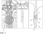
- Fig. 7 shows a typical scene of a trip along with the road map and the calculated pose.
- a high-precision positioning system was used as a reference, which has an error of less than 5 cm.
- the calculated global position had an average total offset of 1.71 m, an average lateral offset of 0.39 m and an average of 0.009 rad relative to the reference system.
- Fig. 7 On the left, the map shows lanes in conjunction with a satellite image as a visualization aid, and the global pose measurement 71. The center shows a camera image and lane measurements generated from it.
- calculated hidden variables for lane centers 72, 73, and 74 and vehicle poses 75 to 78 are shown, with the pose with the highest probability being pose 76.
Landscapes
- Engineering & Computer Science (AREA)
- Radar, Positioning & Navigation (AREA)
- Remote Sensing (AREA)
- Automation & Control Theory (AREA)
- General Physics & Mathematics (AREA)
- Physics & Mathematics (AREA)
- Computer Vision & Pattern Recognition (AREA)
- Transportation (AREA)
- Mechanical Engineering (AREA)
- Multimedia (AREA)
- Human Computer Interaction (AREA)
- Theoretical Computer Science (AREA)
- Traffic Control Systems (AREA)
- Navigation (AREA)
- Aviation & Aerospace Engineering (AREA)
Claims (13)
- Procédé permettant la détermination d'une information de disposition pour un véhicule, dans lequel l'information de disposition comprend une position du véhicule (10) et une orientation du véhicule (10) par rapport à un système de coordonnées stationnaire, dans lequel le procédé comprend :- l'initialisation (21) d'une hypothèse d'information de disposition,dans lequel, lors de l'initialisation, des hypothèses d'information de disposition sont déterminées à une position GPS actuelle, un matériau cartographique est chargé et une hypothèse de disposition de voies de circulation actuelle est déterminée à partir du matériau cartographique pour la position GPS actuelle,dans lequel les étapes suivantes (22) à (28) sont effectuées de manière cyclique,- la mise à jour (22) de l'information de disposition pour le véhicule (10) en fonction de données odométriques du véhicule (10),- la mise à jour (23) de l'information de disposition pour le véhicule (10) en fonction d'une mesure de position globale,- la détection (24) d'une disposition locale de voies de circulation dans un environnement du véhicule (10) avec des capteurs (14) du véhicule (10), dans lequel la disposition locale de voies de circulation indique une disposition de voies de circulation dans l'environnement du véhicule (10) par rapport au véhicule (10),- la détermination (25) d'une première disposition de voies de circulation en fonction de la disposition locale de voies de circulation et de l'information de disposition actuelle pour le véhicule, dans lequel la première disposition de voies de circulation indique une disposition de voies de circulation dans l'environnement du véhicule (10) par rapport au système de coordonnées stationnaire, dans lequel une voie de circulation de la première disposition de voies de circulation comprend une liste de points représentant le centre de la voie de circulation, dans lequel chaque point de la liste de points correspond à une position observée avec les capteurs du véhicule,- la détermination d'une seconde disposition de voies de circulation en fonction d'un matériau cartographique prédéterminé et de l'information de disposition actuelle pour le véhicule, dans lequel la seconde disposition de voies de circulation indique une disposition de voies de circulation dans l'environnement du véhicule (10) par rapport au système de coordonnées stationnaire, dans lequel une voie de circulation de la seconde disposition de voies de circulation comprend une liste de points représentant le centre de la voie de circulation, dans lequel chaque point de la liste de points correspond à un point respectif du matériau cartographique,- la détermination (26) d'une information de similitude en fonction d'une similitude géométrique de la première disposition de voies de circulation et de la seconde disposition de voies de circulation, dans lequel l'information de similitude est déterminée sur la base de comparaisons point par point de points de la liste de points de la première information de voies de circulation avec des points correspondants de la liste de points de la seconde information de voies de circulation, et- la mise à jour (27) de l'information de disposition actuelle pour le véhicule (10) en fonction de l'information de similitude,- la mise à jour (28) de l'hypothèse actuelle de disposition de voies de circulation en fonction de l'information de similitude, dans lequel l'hypothèse de disposition de voies de circulation indique une hypothèse pour une disposition de voies de circulation dans l'environnement du véhicule (10) par rapport au système de coordonnées stationnaires.
- Procédé selon la revendication 1, caractérisé en ce que l'information de disposition du véhicule (10) comprend des paramètres d'une distribution normale multidimensionnelle pour la position et l'orientation du véhicule (10).
- Procédé selon l'une des revendications précédentes,
caractérisé en ce qu'une voie de circulation d'une disposition de voies de circulation comprend une liste de points représentant le centre de la voie de circulation, dans lequel chaque point de la liste de points présente des paramètres d'une distribution normale multidimensionnelle pour une position par rapport au système de coordonnées stationnaire. - Procédé selon l'une des revendications précédentes,
caractérisé en ce que le procédé comprend en outre :- la détection d'une position stationnaire du véhicule (10), dans lequel la position stationnaire indique une position du véhicule (10) par rapport au système de coordonnées stationnaire, et- la mise à jour de l'information de disposition déterminée au préalable pour le véhicule (10) en fonction de la position stationnaire détectée du véhicule (10). - Procédé selon l'une des revendications précédentes,
caractérisé en ce que le procédé est effectué de manière répétée, dans lequel un taux de répétition pour la réalisation répétée du procédé se situe dans une plage de 25 à 400 répétitions par seconde. - Procédé selon l'une des revendications précédentes,
caractérisé en ce que la détermination de l'information de similitude comprend :- la détermination d'informations de voies de circulation pour la première disposition de voies de circulation à l'aide des capteurs du véhicule, dans lequel les informations de voies de circulation comprennent des types de marquage routier et/ou des positions de lignes d'arrêt et/ou des positions de panneaux de signalisation, et- la comparaison des informations de voies de circulation pour la première disposition de voies de circulation avec des informations de voies de circulation basées sur un matériau cartographique pour la seconde disposition de voies de circulation. - Procédé selon l'une des revendications précédentes,
caractérisé en ce que la première disposition de voies de circulation indique une disposition d'au moins deux voies de circulation et/ou la seconde disposition de voies de circulation indique une disposition d'au moins deux voies de circulation, dans lequel la détermination de l'information de similitude comprend :- la détermination de plusieurs informations de similitude de paire, dans lequel chacune des plusieurs informations de similitude de paire est déterminée en fonction d'une similitude géométrique d'une paire respective de deux voies de circulation, dans lequel une paire respective de deux voies de circulation comprend respectivement une voie de circulation provenant de la première disposition de voies de circulation et une voie de circulation provenant de la seconde disposition de voies de circulation. - Procédé selon la revendication 7, caractérisé en ce que la mise à jour de l'information de disposition déterminée au préalable pour le véhicule (10) en fonction de l'information de similitude comprend :- pour une information de similitude de paire respective parmi le plusieurs informations de similitude de paire : la détermination d'une information de mise à jour pondérée respective en fonction de l'information de similitude de paire respective, dans lequel l'information de mise à jour pondérée comprend une information de disposition pour le véhicule (10) en supposant que les voies de circulation de la paire respective concernent la même voie de circulation réelle et dans lequel le poids de l'information de mise à jour pondérée indique une probabilité que les voies de circulation de la paire respective concernent la même voie de circulation réelle, et- la mise à jour de l'information de disposition déterminée au préalable pour le véhicule (10) en fonction des informations de mise à jour pondérées.
- Procédé selon la revendication 8, caractérisé en ce que l'information de disposition du véhicule (10) et les informations de mise à jour pondérées comprennent respectivement des paramètres d'une distribution normale multidimensionnelle pour la position et l'orientation du véhicule (10),
dans lequel la mise à jour de l'information de disposition déterminée au préalable pour le véhicule (10) en fonction de l'information de mise à jour pondérée comprend :- la multiplication de la distribution normale des informations de disposition par les distributions normales des informations de mise à jour. - Dispositif de détermination de disposition permettant la détermination d'une information de disposition pour un véhicule, dans lequel l'information de disposition comprend une position du véhicule (10) et une orientation du véhicule (10) par rapport à un système de coordonnées stationnaire, dans lequel le dispositif de détermination de disposition comprend :- des capteurs pour la détection d'une disposition locale de voies de circulation dans un environnement du véhicule (10), dans lequel la disposition locale de voies de circulation indique une disposition de voies de circulation dans l'environnement du véhicule (10) par rapport au véhicule (10), et- un dispositif de traitement (15) qui est conçu pour initialiser une hypothèse d'information de disposition, dans lequel des hypothèses d'information de disposition peuvent être déterminées à une position GPS actuelle lors de l'initialisation, un matériau cartographique peut être chargé et une hypothèse de disposition de voies de circulation actuelle peut être déterminée à partir du matériau cartographique pour la position GPS actuelle, et pour effectuer les étapes suivantes de manière cyclique,mise à jour de l'information de disposition pour le véhicule (10) en fonction de données odométriques du véhicule (10),mise à jour de l'information de disposition pour le véhicule (10) en fonction d'une mesure de position globale,détermination d'une première disposition de voies de circulation en fonction de la disposition locale de voies de circulation et de l'information de disposition actuelle pour le véhicule (10), dans lequel la première disposition de voies de circulation indique une disposition de voies de circulation dans l'environnement du véhicule (10) par rapport au système de coordonnées stationnaire, dans lequel une voie de circulation de la première disposition de voies de circulation comprend une liste de points représentant le centre de la voie de circulation, dans lequel chaque point de la liste de points correspond à une position observée avec les capteurs du véhicule,détermination d'une seconde disposition de voies de circulation en fonction d'un matériau cartographique prédéterminé et de l'information de disposition actuelle pour le véhicule, dans lequel la seconde disposition de voies de circulation indique une disposition de voies de circulation dans l'environnement du véhicule (10) par rapport au système de coordonnées stationnaire, dans lequel une voie de circulation de la seconde disposition de voies de circulation comprend une liste de points représentant le centre de la voie de circulation, dans lequel chaque point de la liste de points correspond à un point respectif du matériau cartographique,détermination d'une information de similitude en fonction d'une similitude géométrique de la première disposition de voies de circulation et de la seconde disposition de voies de circulation, dans lequel l'information de similitude est déterminée sur la base de comparaisons point par point de points de la liste de points de la première information de voies de circulation avec des points correspondants de la liste de points de la seconde information de voies de circulation, etmise à jour de l'information de disposition actuelle pour le véhicule (10) en fonction de l'information de similitude,mise à jour de l'hypothèse de disposition de voies de circulation actuelle en fonction de l'information de similitude, dans lequel l'hypothèse de disposition de voies de circulation indique une hypothèse pour une disposition de voies de circulation dans l'environnement du véhicule (10) par rapport au système de coordonnées stationnaire.
- Dispositif de détermination de disposition selon la revendication 10, caractérisé en ce que le dispositif de détermination de disposition (11) est conçu pour mettre en œuvre le procédé selon l'une des revendications 1 à 9.
- Véhicule, comprenant :- un dispositif de détermination de disposition (11) selon la revendication 10 ou 11, et- un système d'assistance au conducteur (12) qui fournit une fonction de conduite automatique pour le véhicule (10) et qui est couplé au dispositif de détermination de disposition (11), dans lequel la fonction de conduite automatique est mise en œuvre, sur la base de l'information de disposition mise à jour, par le dispositif de détermination de disposition (11).
- Véhicule selon la revendication 12, dans lequel le dispositif de détermination de disposition (11) est conçu pour mettre en œuvre le procédé selon la revendication 1,
caractérisé en ce que la fonction de conduite automatique est mise en œuvre par le dispositif de détermination de disposition (11) sur la base de l'hypothèse de disposition de voies de circulation mise à jour.
Applications Claiming Priority (2)
| Application Number | Priority Date | Filing Date | Title |
|---|---|---|---|
| DE102015214338.4A DE102015214338A1 (de) | 2015-07-29 | 2015-07-29 | Bestimmung einer Anordnungsinformation für ein Fahrzeug |
| PCT/EP2016/065531 WO2017016799A1 (fr) | 2015-07-29 | 2016-07-01 | Détermination d'une information de disposition pour un véhicule |
Publications (2)
| Publication Number | Publication Date |
|---|---|
| EP3329216A1 EP3329216A1 (fr) | 2018-06-06 |
| EP3329216B1 true EP3329216B1 (fr) | 2025-05-21 |
Family
ID=56296824
Family Applications (1)
| Application Number | Title | Priority Date | Filing Date |
|---|---|---|---|
| EP16733965.4A Active EP3329216B1 (fr) | 2015-07-29 | 2016-07-01 | Détermination d'une information de disposition pour un véhicule |
Country Status (5)
| Country | Link |
|---|---|
| US (1) | US10773719B2 (fr) |
| EP (1) | EP3329216B1 (fr) |
| CN (1) | CN108139225B (fr) |
| DE (1) | DE102015214338A1 (fr) |
| WO (1) | WO2017016799A1 (fr) |
Families Citing this family (47)
| Publication number | Priority date | Publication date | Assignee | Title |
|---|---|---|---|---|
| US9616773B2 (en) | 2015-05-11 | 2017-04-11 | Uber Technologies, Inc. | Detecting objects within a vehicle in connection with a service |
| DE102015214338A1 (de) | 2015-07-29 | 2017-02-02 | Volkswagen Aktiengesellschaft | Bestimmung einer Anordnungsinformation für ein Fahrzeug |
| MX364577B (es) * | 2015-08-28 | 2019-05-02 | Nissan Motor | Dispositivo de estimacion de posicion de vehiculo, metodo de estimacion de posicion de vehiculo. |
| US10303176B2 (en) * | 2015-10-15 | 2019-05-28 | Ford Global Technologies, Llc | Determining variance factors for complex road segments |
| US10712160B2 (en) | 2015-12-10 | 2020-07-14 | Uatc, Llc | Vehicle traction map for autonomous vehicles |
| US9841763B1 (en) | 2015-12-16 | 2017-12-12 | Uber Technologies, Inc. | Predictive sensor array configuration system for an autonomous vehicle |
| US9840256B1 (en) | 2015-12-16 | 2017-12-12 | Uber Technologies, Inc. | Predictive sensor array configuration system for an autonomous vehicle |
| US9990548B2 (en) | 2016-03-09 | 2018-06-05 | Uber Technologies, Inc. | Traffic signal analysis system |
| DE102016209232B4 (de) * | 2016-05-27 | 2022-12-22 | Volkswagen Aktiengesellschaft | Verfahren, Vorrichtung und computerlesbares Speichermedium mit Instruktionen zur Bestimmung der lateralen Position eines Fahrzeuges relativ zu den Fahrstreifen einer Fahrbahn |
| US10678262B2 (en) | 2016-07-01 | 2020-06-09 | Uatc, Llc | Autonomous vehicle localization using image analysis and manipulation |
| US10373002B2 (en) * | 2017-03-31 | 2019-08-06 | Here Global B.V. | Method, apparatus, and system for a parametric representation of lane lines |
| CN113822939A (zh) * | 2017-07-06 | 2021-12-21 | 华为技术有限公司 | 车载传感器的外部参数标定的方法和设备 |
| DE102017212222B3 (de) * | 2017-07-18 | 2018-10-25 | Audi Ag | Verfahren zum Betreiben einer Anzeigeeinrichtung eines Kraftfahrzeugs, Fahrerassistenzeinrichtung, und Kraftfahrzeug |
| US10611371B2 (en) * | 2017-09-14 | 2020-04-07 | Toyota Motor Engineering & Manufacturing North America, Inc. | System and method for vehicle lane change prediction using structural recurrent neural networks |
| US10684132B2 (en) | 2018-03-19 | 2020-06-16 | Here Global B.V. | Generation and update of a lane network graph model |
| US11334753B2 (en) | 2018-04-30 | 2022-05-17 | Uatc, Llc | Traffic signal state classification for autonomous vehicles |
| JP6956268B2 (ja) * | 2018-07-11 | 2021-11-02 | 日産自動車株式会社 | 走行環境情報の生成方法、運転制御方法、走行環境情報生成装置 |
| DE102018117660A1 (de) | 2018-07-20 | 2020-01-23 | Man Truck & Bus Se | Verfahren und system zum bestimmen einer position eines fahrzeugs |
| JP7127436B2 (ja) * | 2018-08-31 | 2022-08-30 | 株式会社デンソー | 地図生成装置及び地図生成プログラム |
| WO2020048623A1 (fr) * | 2018-09-07 | 2020-03-12 | Huawei Technologies Co., Ltd. | Estimation d'une pose d'un robot |
| DE102019212602A1 (de) * | 2018-09-26 | 2020-03-26 | Robert Bosch Gmbh | Verfahren zum quantitativen Charakterisieren zumindest einer zeitlichen Sequenz eines Objektattribut-Fehlers eines Objektes |
| EP3640679B1 (fr) * | 2018-10-15 | 2023-06-07 | Zenuity AB | Procédé d'affectation de véhicule autonome à une voie de circulation |
| JP7176376B2 (ja) * | 2018-11-30 | 2022-11-22 | トヨタ自動車株式会社 | 車両の制御装置 |
| DE102018221864A1 (de) | 2018-12-17 | 2020-06-18 | Volkswagen Aktiengesellschaft | Verfahren und System zum Bestimmen einer Trajektorie eines Fahrzeugs |
| CN110427520B (zh) * | 2019-07-04 | 2022-08-23 | 重庆邮电大学 | 一种基于自适应局部和分组关联策略的slam数据关联方法 |
| US11788861B2 (en) | 2019-08-31 | 2023-10-17 | Nvidia Corporation | Map creation and localization for autonomous driving applications |
| DE102019123659A1 (de) | 2019-09-04 | 2021-03-04 | Sick Ag | Verfahren zum Erstellen einer Karte, Verfahren zum Ermitteln einer Pose eines Fahrzeugs, Kartierungsvorrichtungen und Lokalisierungsvorrichtungen |
| DE102019216722A1 (de) * | 2019-10-30 | 2021-05-06 | Zf Friedrichshafen Ag | Verfahren zum Lokalisieren eines Fahrzeugs in einer digitalen Karte |
| US11989952B2 (en) | 2019-12-10 | 2024-05-21 | Samsung Electronics Co., Ltd. | Systems and methods for trajectory prediction |
| US11238607B2 (en) | 2020-03-31 | 2022-02-01 | Denso International America, Inc. | System and method for measuring the accuracy of an electronic map or a localization of a vehicle |
| DE102020115718A1 (de) | 2020-06-15 | 2021-12-16 | Man Truck & Bus Se | Verfahren zur Bestimmung einer Nutzungsart eines Landmarkenmusters für eine Eigenlokalisierung eines Fahrzeugs, sowie elektronisches Eigenlokalisierungssystem für ein Fahrzeug |
| CN112325885A (zh) * | 2020-10-30 | 2021-02-05 | 哈尔滨工业大学 | 一种基于数学统计特征的因子图协同定位算法 |
| CN112945224B (zh) * | 2021-02-05 | 2022-12-09 | 哈尔滨工程大学 | 一种采用因子图和和积算法的多auv协同导航方法 |
| DE102021107385A1 (de) | 2021-03-24 | 2022-09-29 | Bayerische Motoren Werke Aktiengesellschaft | Verfahren zum Bestimmen, in welcher Fahrspur sich ein Fahrzeug befindet und System zum Betreiben einer Fahrerassistenzfunktion |
| US12172638B2 (en) * | 2021-07-19 | 2024-12-24 | Embark Trucks, Inc. | Dynamically modifiable map |
| DE102021211988A1 (de) | 2021-10-25 | 2023-04-27 | Robert Bosch Gesellschaft mit beschränkter Haftung | Verfahren zum Generieren einer Kartendarstellung für Fahrzeuge |
| DE102021128116B4 (de) | 2021-10-28 | 2025-03-13 | Cariad Se | System und Verfahren zum Plausibilisieren einer Fahrzeugumgebungshypothese für ein Kraftfahrzeug |
| CN114018274B (zh) * | 2021-11-18 | 2024-03-26 | 阿波罗智能技术(北京)有限公司 | 车辆定位方法、装置及电子设备 |
| CN116263334B (zh) * | 2021-12-15 | 2025-10-31 | 腾讯科技(深圳)有限公司 | 定位方法、装置、计算机设备、存储介质和程序产品 |
| DE102022103856A1 (de) | 2022-02-18 | 2023-08-24 | Bayerische Motoren Werke Aktiengesellschaft | Verfahren und Vorrichtung zur Erkennung eines Problems bei der Ermittlung eines Fahrpfades |
| US20230266142A1 (en) * | 2022-02-23 | 2023-08-24 | Here Global B.V. | Method, apparatus, and system for reconstructing a road linear feature |
| WO2023165718A1 (fr) * | 2022-03-04 | 2023-09-07 | Huawei Technologies Co., Ltd. | Appareil et procédés de localisation visuelle avec représentation cartographique implicite compacte |
| DE102022206144A1 (de) | 2022-06-20 | 2023-12-21 | Continental Autonomous Mobility Germany GmbH | Verfahren zur Lokalisierung eines Fahrzeugs, Sensoreinrichtung, Fahrzeug und Computerprogrammprodukt |
| DE102022212704A1 (de) | 2022-11-28 | 2024-05-29 | Robert Bosch Gesellschaft mit beschränkter Haftung | Verfahren zum Abgleichen einer digitalen Straßenkarte |
| EP4478304A1 (fr) * | 2023-06-13 | 2024-12-18 | Zenseact AB | Estimation de route basée sur un modèle |
| DE102023123989A1 (de) * | 2023-09-06 | 2025-03-06 | Valeo Schalter Und Sensoren Gmbh | Verfahren zum Lokalisieren eines Fahrzeugs innerhalb einer Landkarte, in der zumindest eine Linie eingezeichnet ist |
| DE102024201714A1 (de) * | 2024-02-23 | 2025-08-28 | Volkswagen Aktiengesellschaft | Verfahren zum Erstellen einer digitalen Karte einer Umgebung eines Fahrzeugs mittels eines Kartierungssystems, sowie Kartierungssystem |
Citations (3)
| Publication number | Priority date | Publication date | Assignee | Title |
|---|---|---|---|---|
| US20130162824A1 (en) * | 2011-12-22 | 2013-06-27 | Electronics And Telecommunications Research Institute | Apparatus and method for recognizing current position of vehicle using internal network of the vehicle and image sensor |
| US20140093131A1 (en) * | 2012-10-01 | 2014-04-03 | Xerox Corporation | Visibility improvement in bad weather using enchanced reality |
| US20140343842A1 (en) * | 2013-05-17 | 2014-11-20 | Honda Motor Co., Ltd. | Localization using road markings |
Family Cites Families (19)
| Publication number | Priority date | Publication date | Assignee | Title |
|---|---|---|---|---|
| US7610146B2 (en) * | 1997-10-22 | 2009-10-27 | Intelligent Technologies International, Inc. | Vehicle position determining system and method |
| DE102006040334A1 (de) * | 2006-08-29 | 2008-03-06 | Robert Bosch Gmbh | Verfahren für die Spurerfassung mit einem Fahrerassistenzsystem und Fahrerassistenzsystem |
| DE102006040333A1 (de) * | 2006-08-29 | 2008-03-06 | Robert Bosch Gmbh | Verfahren für die Spurerfassung mit einem Fahrerassistenzsystem eines Fahrzeugs |
| CN101641610A (zh) * | 2007-02-21 | 2010-02-03 | 电子地图北美公司 | 用于包含绝对及相对坐标的车辆导航及领航的系统及方法 |
| JP4886597B2 (ja) * | 2007-05-25 | 2012-02-29 | アイシン・エィ・ダブリュ株式会社 | レーン判定装置及びレーン判定方法、並びにそれを用いたナビゲーション装置 |
| US8775063B2 (en) * | 2009-01-26 | 2014-07-08 | GM Global Technology Operations LLC | System and method of lane path estimation using sensor fusion |
| DE102010033729B4 (de) | 2010-08-07 | 2014-05-08 | Audi Ag | Verfahren und Vorrichtung zum Bestimmen der Position eines Fahrzeugs auf einer Fahrbahn sowie Kraftwagen mit einer solchen Vorrichtung |
| US8452535B2 (en) * | 2010-12-13 | 2013-05-28 | GM Global Technology Operations LLC | Systems and methods for precise sub-lane vehicle positioning |
| US8744666B2 (en) * | 2011-07-06 | 2014-06-03 | Peloton Technology, Inc. | Systems and methods for semi-autonomous vehicular convoys |
| US10520952B1 (en) * | 2011-07-06 | 2019-12-31 | Peloton Technology, Inc. | Devices, systems, and methods for transmitting vehicle data |
| CN102901505B (zh) * | 2011-07-29 | 2015-10-07 | 上海博泰悦臻电子设备制造有限公司 | 导航系统及道路匹配方法与装置 |
| US8700251B1 (en) * | 2012-04-13 | 2014-04-15 | Google Inc. | System and method for automatically detecting key behaviors by vehicles |
| CN103954275B (zh) * | 2014-04-01 | 2017-02-08 | 西安交通大学 | 基于车道线检测和gis地图信息开发的视觉导航方法 |
| CN104089619B (zh) * | 2014-05-14 | 2016-12-07 | 北京联合大学 | 无人驾驶汽车的gps导航地图精确匹配系统及其操作方法 |
| CN104120645B (zh) * | 2014-06-20 | 2016-07-06 | 南京理工技术转移中心有限公司 | 一种路面状况自动检测数据定位系统与定位方法 |
| US9530062B2 (en) * | 2014-12-23 | 2016-12-27 | Volkswagen Ag | Fused raised pavement marker detection for autonomous driving using lidar and camera |
| US9511767B1 (en) * | 2015-07-01 | 2016-12-06 | Toyota Motor Engineering & Manufacturing North America, Inc. | Autonomous vehicle action planning using behavior prediction |
| DE102015214338A1 (de) | 2015-07-29 | 2017-02-02 | Volkswagen Aktiengesellschaft | Bestimmung einer Anordnungsinformation für ein Fahrzeug |
| US9958283B2 (en) * | 2016-05-25 | 2018-05-01 | Here Global B.V. | Determining speed information |
-
2015
- 2015-07-29 DE DE102015214338.4A patent/DE102015214338A1/de active Granted
-
2016
- 2016-07-01 EP EP16733965.4A patent/EP3329216B1/fr active Active
- 2016-07-01 WO PCT/EP2016/065531 patent/WO2017016799A1/fr not_active Ceased
- 2016-07-01 US US15/748,279 patent/US10773719B2/en active Active
- 2016-07-01 CN CN201680056534.3A patent/CN108139225B/zh active Active
Patent Citations (3)
| Publication number | Priority date | Publication date | Assignee | Title |
|---|---|---|---|---|
| US20130162824A1 (en) * | 2011-12-22 | 2013-06-27 | Electronics And Telecommunications Research Institute | Apparatus and method for recognizing current position of vehicle using internal network of the vehicle and image sensor |
| US20140093131A1 (en) * | 2012-10-01 | 2014-04-03 | Xerox Corporation | Visibility improvement in bad weather using enchanced reality |
| US20140343842A1 (en) * | 2013-05-17 | 2014-11-20 | Honda Motor Co., Ltd. | Localization using road markings |
Non-Patent Citations (5)
| Title |
|---|
| GRUYER DOMINIQUE ET AL: "Map-aided localization with lateral perception", 2014 IEEE INTELLIGENT VEHICLES SYMPOSIUM PROCEEDINGS, IEEE, 8 June 2014 (2014-06-08), pages 674 - 680, XP032620378, [retrieved on 20140715], DOI: 10.1109/IVS.2014.6856528 * |
| SCHINDLER ANDREAS: "Vehicle self-localization with high-precision digital maps", 2013 IEEE INTELLIGENT VEHICLES SYMPOSIUM WORKSHOPS (IV WORKSHOPS), IEEE, 23 June 2013 (2013-06-23), pages 134 - 139, XP032491728, [retrieved on 20130927], DOI: 10.1109/IV WORKSHOPS.2013.6615239 * |
| SCHREIBER MARKUS ET AL: "LaneLoc: Lane marking based localization using highly accurate maps", 2013 IEEE INTELLIGENT VEHICLES SYMPOSIUM (IV), IEEE, 23 June 2013 (2013-06-23), pages 449 - 454, XP032501902, ISSN: 1931-0587, [retrieved on 20131010], DOI: 10.1109/IVS.2013.6629509 * |
| TAO Z ET AL: "Mapping and localization using GPS, lane markings and proprioceptive sensors", 2013 IEEE/RSJ INTERNATIONAL CONFERENCE ON INTELLIGENT ROBOTS AND SYSTEMS(ROS), IEEE, 3 November 2013 (2013-11-03), pages 406 - 412, XP032537362, ISSN: 2153-0858, [retrieved on 20131226], DOI: 10.1109/IROS.2013.6696383 * |
| WEI LIJUN ET AL: "Augmenting Vehicle Localization Accuracy with Cameras and 3D Road Infrastructure Database", 19 March 2015, ICIAP: INTERNATIONAL CONFERENCE ON IMAGE ANALYSIS AND PROCESSING, 17TH INTERNATIONAL CONFERENCE, NAPLES, ITALY, SEPTEMBER 9-13, 2013. PROCEEDINGS; [LECTURE NOTES IN COMPUTER SCIENCE; LECT.NOTES COMPUTER], SPRINGER, BERLIN, HEIDELBERG, PAGE(S) 194 - 2, ISBN: 978-3-642-17318-9, XP047339440 * |
Also Published As
| Publication number | Publication date |
|---|---|
| US20180304891A1 (en) | 2018-10-25 |
| DE102015214338A1 (de) | 2017-02-02 |
| CN108139225B (zh) | 2021-08-20 |
| CN108139225A (zh) | 2018-06-08 |
| WO2017016799A1 (fr) | 2017-02-02 |
| US10773719B2 (en) | 2020-09-15 |
| EP3329216A1 (fr) | 2018-06-06 |
Similar Documents
| Publication | Publication Date | Title |
|---|---|---|
| EP3329216B1 (fr) | Détermination d'une information de disposition pour un véhicule | |
| DE102010005293B4 (de) | System und Verfahren zur Spurpfadschätzung unter Verwendung einer Sensorvereinigung | |
| DE102018116633B4 (de) | Vorrichtung und verfahren zum steuern einer fahrmodusumschaltung eines fahrzeugs und fahrzeugsystem | |
| DE102015122825B4 (de) | Techniken zum Gruppieren von Zielelementen für eine Objektfusion | |
| DE112019007451T5 (de) | Hochpräzises Verfahren sowie Gerät zur Fahrzeugpositionierung in mehreren Szenen, und fahrzeugmontiertes Terminal | |
| DE102013107861A1 (de) | Tracking von Strassen-Fahrzeugen mit Sensoren unterschiedlicher Ausführungsarten | |
| DE102017116088A1 (de) | Vorrichtung und Verfahren zum Abschätzen einer Position eines Fahrzeugs | |
| DE102019115240A1 (de) | Systeme und verfahren für die anwendung von landkarten zur verbesserung von objektverfolgung, fahrstreifenzuordnung und klassifizierung | |
| EP3465088B1 (fr) | Procédé, dispositif et support d'informations lisible par ordinateur comprenant des instructions pour déterminer la position latérale d'un véhicule par rapport aux bandes de circulation d'une chaussée | |
| WO2021043505A1 (fr) | Procédé et dispositif de détermination d'une trajectoire d'un véhicule | |
| DE112015006622T5 (de) | Fahrspurbestimmungsvorrichtung und Fahrspurbestimmungsverfahren | |
| EP3581886B1 (fr) | Procédé et dispositif de détermination d'une position d'un véhicule automobile | |
| DE102020200169B3 (de) | Verfahren zur Zusammenführung mehrerer Datensätze für die Erzeugung eines aktuellen Spurmodells einer Fahrbahn und Vorrichtung zur Datenverarbeitung | |
| DE102018201154A1 (de) | Verfahren zur Kalibrierung von Sensoren und/oder von Sensoranordnungen | |
| DE112018007134T5 (de) | Fahrassistenzssystem, fahrassistenzverfahren und fahrassistenzprogramm | |
| DE102020105619A1 (de) | System und verfahren zur bestimmung der fahrzeugposition | |
| EP3610224B1 (fr) | Procédé, dispositif et support d'enregistrement lisible par ordinateur comprenant des instructions servant à estimer une position d'un véhicule automobile | |
| DE102022108712A1 (de) | Gemeinsame Schätzung und Korrektur eines Ausrichtungsfehlers einer LIDAR-Mittelachse und eines Lokalisierungsfehlers eines Trägerfahrzeugs | |
| EP3637311A1 (fr) | Dispositif et procédé de détermination des informations de hauteur d'un objet dans l'environnement d'un véhicule | |
| DE102016003261A1 (de) | Verfahren zur Selbstlokalisierung eines Fahrzeugs in einer Fahrzeugumgebung | |
| EP3865915B1 (fr) | Estimation de la position dans différents systèmes de coordonnées | |
| DE102023132314B3 (de) | System und verfahren zum zusammenführen von zwei oder mehr versionen von kartendaten auf der grundlage der räumlichen kalman-filterung | |
| DE112022002019T5 (de) | Fahrvorrichtung, fahrzeug und verfahren zum automatisierten fahren und/oder assistierten fahren | |
| DE102015225577A1 (de) | Verbessertes Verfahren zum Ermitteln der Randbebauung einer Fahrbahn für die Lokalisierung von Kraftfahrzeugen | |
| DE102023122961A1 (de) | Wahrnehmungs- und kartenrandzuordnungssystem zumanpassen von inkonsistenten wahrnehmungs- und kartendaten |
Legal Events
| Date | Code | Title | Description |
|---|---|---|---|
| STAA | Information on the status of an ep patent application or granted ep patent |
Free format text: STATUS: THE INTERNATIONAL PUBLICATION HAS BEEN MADE |
|
| PUAI | Public reference made under article 153(3) epc to a published international application that has entered the european phase |
Free format text: ORIGINAL CODE: 0009012 |
|
| STAA | Information on the status of an ep patent application or granted ep patent |
Free format text: STATUS: REQUEST FOR EXAMINATION WAS MADE |
|
| 17P | Request for examination filed |
Effective date: 20180228 |
|
| AK | Designated contracting states |
Kind code of ref document: A1 Designated state(s): AL AT BE BG CH CY CZ DE DK EE ES FI FR GB GR HR HU IE IS IT LI LT LU LV MC MK MT NL NO PL PT RO RS SE SI SK SM TR |
|
| AX | Request for extension of the european patent |
Extension state: BA ME |
|
| RIN1 | Information on inventor provided before grant (corrected) |
Inventor name: SPEHR, JENS Inventor name: HEIDENREICH, TONI |
|
| DAV | Request for validation of the european patent (deleted) | ||
| DAX | Request for extension of the european patent (deleted) | ||
| STAA | Information on the status of an ep patent application or granted ep patent |
Free format text: STATUS: EXAMINATION IS IN PROGRESS |
|
| 17Q | First examination report despatched |
Effective date: 20210607 |
|
| RIC1 | Information provided on ipc code assigned before grant |
Ipc: G01C 21/30 20060101ALI20240930BHEP Ipc: G01C 21/36 20060101AFI20240930BHEP |
|
| GRAP | Despatch of communication of intention to grant a patent |
Free format text: ORIGINAL CODE: EPIDOSNIGR1 |
|
| STAA | Information on the status of an ep patent application or granted ep patent |
Free format text: STATUS: GRANT OF PATENT IS INTENDED |
|
| INTG | Intention to grant announced |
Effective date: 20241212 |
|
| P01 | Opt-out of the competence of the unified patent court (upc) registered |
Free format text: CASE NUMBER: APP_67468/2024 Effective date: 20241220 |
|
| GRAS | Grant fee paid |
Free format text: ORIGINAL CODE: EPIDOSNIGR3 |
|
| GRAA | (expected) grant |
Free format text: ORIGINAL CODE: 0009210 |
|
| STAA | Information on the status of an ep patent application or granted ep patent |
Free format text: STATUS: THE PATENT HAS BEEN GRANTED |
|
| AK | Designated contracting states |
Kind code of ref document: B1 Designated state(s): AL AT BE BG CH CY CZ DE DK EE ES FI FR GB GR HR HU IE IS IT LI LT LU LV MC MK MT NL NO PL PT RO RS SE SI SK SM TR |
|
| REG | Reference to a national code |
Ref country code: GB Ref legal event code: FG4D Free format text: NOT ENGLISH |
|
| REG | Reference to a national code |
Ref country code: CH Ref legal event code: EP |
|
| REG | Reference to a national code |
Ref country code: DE Ref legal event code: R096 Ref document number: 502016016981 Country of ref document: DE |
|
| REG | Reference to a national code |
Ref country code: IE Ref legal event code: FG4D Free format text: LANGUAGE OF EP DOCUMENT: GERMAN |
|
| REG | Reference to a national code |
Ref country code: NL Ref legal event code: MP Effective date: 20250521 |
|
| PG25 | Lapsed in a contracting state [announced via postgrant information from national office to epo] |
Ref country code: ES Free format text: LAPSE BECAUSE OF FAILURE TO SUBMIT A TRANSLATION OF THE DESCRIPTION OR TO PAY THE FEE WITHIN THE PRESCRIBED TIME-LIMIT Effective date: 20250521 Ref country code: FI Free format text: LAPSE BECAUSE OF FAILURE TO SUBMIT A TRANSLATION OF THE DESCRIPTION OR TO PAY THE FEE WITHIN THE PRESCRIBED TIME-LIMIT Effective date: 20250521 Ref country code: PT Free format text: LAPSE BECAUSE OF FAILURE TO SUBMIT A TRANSLATION OF THE DESCRIPTION OR TO PAY THE FEE WITHIN THE PRESCRIBED TIME-LIMIT Effective date: 20250922 |
|
| PGFP | Annual fee paid to national office [announced via postgrant information from national office to epo] |
Ref country code: DE Payment date: 20250731 Year of fee payment: 10 |
|
| REG | Reference to a national code |
Ref country code: LT Ref legal event code: MG9D |
|
| PG25 | Lapsed in a contracting state [announced via postgrant information from national office to epo] |
Ref country code: NO Free format text: LAPSE BECAUSE OF FAILURE TO SUBMIT A TRANSLATION OF THE DESCRIPTION OR TO PAY THE FEE WITHIN THE PRESCRIBED TIME-LIMIT Effective date: 20250821 Ref country code: GR Free format text: LAPSE BECAUSE OF FAILURE TO SUBMIT A TRANSLATION OF THE DESCRIPTION OR TO PAY THE FEE WITHIN THE PRESCRIBED TIME-LIMIT Effective date: 20250822 |
|
| PG25 | Lapsed in a contracting state [announced via postgrant information from national office to epo] |
Ref country code: NL Free format text: LAPSE BECAUSE OF FAILURE TO SUBMIT A TRANSLATION OF THE DESCRIPTION OR TO PAY THE FEE WITHIN THE PRESCRIBED TIME-LIMIT Effective date: 20250521 Ref country code: PL Free format text: LAPSE BECAUSE OF FAILURE TO SUBMIT A TRANSLATION OF THE DESCRIPTION OR TO PAY THE FEE WITHIN THE PRESCRIBED TIME-LIMIT Effective date: 20250521 |
|
| PG25 | Lapsed in a contracting state [announced via postgrant information from national office to epo] |
Ref country code: BG Free format text: LAPSE BECAUSE OF FAILURE TO SUBMIT A TRANSLATION OF THE DESCRIPTION OR TO PAY THE FEE WITHIN THE PRESCRIBED TIME-LIMIT Effective date: 20250521 |
|
| PGFP | Annual fee paid to national office [announced via postgrant information from national office to epo] |
Ref country code: GB Payment date: 20250722 Year of fee payment: 10 |
|
| PG25 | Lapsed in a contracting state [announced via postgrant information from national office to epo] |
Ref country code: HR Free format text: LAPSE BECAUSE OF FAILURE TO SUBMIT A TRANSLATION OF THE DESCRIPTION OR TO PAY THE FEE WITHIN THE PRESCRIBED TIME-LIMIT Effective date: 20250521 |
|
| PGFP | Annual fee paid to national office [announced via postgrant information from national office to epo] |
Ref country code: FR Payment date: 20250725 Year of fee payment: 10 |
|
| PG25 | Lapsed in a contracting state [announced via postgrant information from national office to epo] |
Ref country code: RS Free format text: LAPSE BECAUSE OF FAILURE TO SUBMIT A TRANSLATION OF THE DESCRIPTION OR TO PAY THE FEE WITHIN THE PRESCRIBED TIME-LIMIT Effective date: 20250821 |
|
| PG25 | Lapsed in a contracting state [announced via postgrant information from national office to epo] |
Ref country code: IS Free format text: LAPSE BECAUSE OF FAILURE TO SUBMIT A TRANSLATION OF THE DESCRIPTION OR TO PAY THE FEE WITHIN THE PRESCRIBED TIME-LIMIT Effective date: 20250921 |
|
| PG25 | Lapsed in a contracting state [announced via postgrant information from national office to epo] |
Ref country code: LV Free format text: LAPSE BECAUSE OF FAILURE TO SUBMIT A TRANSLATION OF THE DESCRIPTION OR TO PAY THE FEE WITHIN THE PRESCRIBED TIME-LIMIT Effective date: 20250521 |
|
| PG25 | Lapsed in a contracting state [announced via postgrant information from national office to epo] |
Ref country code: DK Free format text: LAPSE BECAUSE OF FAILURE TO SUBMIT A TRANSLATION OF THE DESCRIPTION OR TO PAY THE FEE WITHIN THE PRESCRIBED TIME-LIMIT Effective date: 20250521 Ref country code: SM Free format text: LAPSE BECAUSE OF FAILURE TO SUBMIT A TRANSLATION OF THE DESCRIPTION OR TO PAY THE FEE WITHIN THE PRESCRIBED TIME-LIMIT Effective date: 20250521 |
|
| PG25 | Lapsed in a contracting state [announced via postgrant information from national office to epo] |
Ref country code: CZ Free format text: LAPSE BECAUSE OF FAILURE TO SUBMIT A TRANSLATION OF THE DESCRIPTION OR TO PAY THE FEE WITHIN THE PRESCRIBED TIME-LIMIT Effective date: 20250521 |
|
| PG25 | Lapsed in a contracting state [announced via postgrant information from national office to epo] |
Ref country code: EE Free format text: LAPSE BECAUSE OF FAILURE TO SUBMIT A TRANSLATION OF THE DESCRIPTION OR TO PAY THE FEE WITHIN THE PRESCRIBED TIME-LIMIT Effective date: 20250521 |
|
| PG25 | Lapsed in a contracting state [announced via postgrant information from national office to epo] |
Ref country code: SK Free format text: LAPSE BECAUSE OF FAILURE TO SUBMIT A TRANSLATION OF THE DESCRIPTION OR TO PAY THE FEE WITHIN THE PRESCRIBED TIME-LIMIT Effective date: 20250521 Ref country code: RO Free format text: LAPSE BECAUSE OF FAILURE TO SUBMIT A TRANSLATION OF THE DESCRIPTION OR TO PAY THE FEE WITHIN THE PRESCRIBED TIME-LIMIT Effective date: 20250521 |
|
| PG25 | Lapsed in a contracting state [announced via postgrant information from national office to epo] |
Ref country code: IT Free format text: LAPSE BECAUSE OF FAILURE TO SUBMIT A TRANSLATION OF THE DESCRIPTION OR TO PAY THE FEE WITHIN THE PRESCRIBED TIME-LIMIT Effective date: 20250521 |
|
| REG | Reference to a national code |
Ref country code: CH Ref legal event code: H13 Free format text: ST27 STATUS EVENT CODE: U-0-0-H10-H13 (AS PROVIDED BY THE NATIONAL OFFICE) Effective date: 20260224 Ref country code: DE Ref legal event code: R097 Ref document number: 502016016981 Country of ref document: DE |
|
| PG25 | Lapsed in a contracting state [announced via postgrant information from national office to epo] |
Ref country code: LU Free format text: LAPSE BECAUSE OF NON-PAYMENT OF DUE FEES Effective date: 20250701 |
|
| REG | Reference to a national code |
Ref country code: BE Ref legal event code: MM Effective date: 20250731 |
|
| PLBE | No opposition filed within time limit |
Free format text: ORIGINAL CODE: 0009261 |
|
| STAA | Information on the status of an ep patent application or granted ep patent |
Free format text: STATUS: NO OPPOSITION FILED WITHIN TIME LIMIT |
|
| REG | Reference to a national code |
Ref country code: CH Ref legal event code: L10 Free format text: ST27 STATUS EVENT CODE: U-0-0-L10-L00 (AS PROVIDED BY THE NATIONAL OFFICE) Effective date: 20260402 |
|
| PG25 | Lapsed in a contracting state [announced via postgrant information from national office to epo] |
Ref country code: BE Free format text: LAPSE BECAUSE OF NON-PAYMENT OF DUE FEES Effective date: 20250731 |
|
| PG25 | Lapsed in a contracting state [announced via postgrant information from national office to epo] |
Ref country code: CH Free format text: LAPSE BECAUSE OF NON-PAYMENT OF DUE FEES Effective date: 20250731 |
|
| 26N | No opposition filed |
Effective date: 20260224 |