EP3329264B1 - Kältemittelanalysator und verfahren zu dessen verwendung - Google Patents
Kältemittelanalysator und verfahren zu dessen verwendung Download PDFInfo
- Publication number
- EP3329264B1 EP3329264B1 EP16757106.6A EP16757106A EP3329264B1 EP 3329264 B1 EP3329264 B1 EP 3329264B1 EP 16757106 A EP16757106 A EP 16757106A EP 3329264 B1 EP3329264 B1 EP 3329264B1
- Authority
- EP
- European Patent Office
- Prior art keywords
- refrigerant
- sensing device
- analyzer
- scrubber
- stream
- Prior art date
- Legal status (The legal status is an assumption and is not a legal conclusion. Google has not performed a legal analysis and makes no representation as to the accuracy of the status listed.)
- Active
Links
Images


Classifications
-
- G—PHYSICS
- G01—MEASURING; TESTING
- G01N—INVESTIGATING OR ANALYSING MATERIALS BY DETERMINING THEIR CHEMICAL OR PHYSICAL PROPERTIES
- G01N21/00—Investigating or analysing materials by the use of optical means, i.e. using sub-millimetre waves, infrared, visible or ultraviolet light
- G01N21/17—Systems in which incident light is modified in accordance with the properties of the material investigated
- G01N21/25—Colour; Spectral properties, i.e. comparison of effect of material on the light at two or more different wavelengths or wavelength bands
- G01N21/31—Investigating relative effect of material at wavelengths characteristic of specific elements or molecules, e.g. atomic absorption spectrometry
- G01N21/35—Investigating relative effect of material at wavelengths characteristic of specific elements or molecules, e.g. atomic absorption spectrometry using infrared light
- G01N21/3504—Investigating relative effect of material at wavelengths characteristic of specific elements or molecules, e.g. atomic absorption spectrometry using infrared light for analysing gases, e.g. multi-gas analysis
-
- G—PHYSICS
- G01—MEASURING; TESTING
- G01N—INVESTIGATING OR ANALYSING MATERIALS BY DETERMINING THEIR CHEMICAL OR PHYSICAL PROPERTIES
- G01N27/00—Investigating or analysing materials by the use of electric, electrochemical, or magnetic means
- G01N27/26—Investigating or analysing materials by the use of electric, electrochemical, or magnetic means by investigating electrochemical variables; by using electrolysis or electrophoresis
- G01N27/27—Association of two or more measuring systems or cells, each measuring a different parameter, where the measurement results may be either used independently, the systems or cells being physically associated, or combined to produce a value for a further parameter
-
- G—PHYSICS
- G01—MEASURING; TESTING
- G01N—INVESTIGATING OR ANALYSING MATERIALS BY DETERMINING THEIR CHEMICAL OR PHYSICAL PROPERTIES
- G01N33/00—Investigating or analysing materials by specific methods not covered by groups G01N1/00 - G01N31/00
- G01N33/0004—Gaseous mixtures, e.g. polluted air
- G01N33/0009—General constructional details of gas analysers, e.g. portable test equipment
- G01N33/0027—General constructional details of gas analysers, e.g. portable test equipment concerning the detector
- G01N33/0031—General constructional details of gas analysers, e.g. portable test equipment concerning the detector comprising two or more sensors, e.g. a sensor array
- G01N33/0032—General constructional details of gas analysers, e.g. portable test equipment concerning the detector comprising two or more sensors, e.g. a sensor array using two or more different physical functioning modes
-
- G—PHYSICS
- G01—MEASURING; TESTING
- G01N—INVESTIGATING OR ANALYSING MATERIALS BY DETERMINING THEIR CHEMICAL OR PHYSICAL PROPERTIES
- G01N21/00—Investigating or analysing materials by the use of optical means, i.e. using sub-millimetre waves, infrared, visible or ultraviolet light
- G01N21/17—Systems in which incident light is modified in accordance with the properties of the material investigated
- G01N21/59—Transmissivity
- G01N21/61—Non-dispersive gas analysers
-
- G—PHYSICS
- G01—MEASURING; TESTING
- G01N—INVESTIGATING OR ANALYSING MATERIALS BY DETERMINING THEIR CHEMICAL OR PHYSICAL PROPERTIES
- G01N21/00—Investigating or analysing materials by the use of optical means, i.e. using sub-millimetre waves, infrared, visible or ultraviolet light
- G01N21/84—Systems specially adapted for particular applications
- G01N21/88—Investigating the presence of flaws or contamination
- G01N21/94—Investigating contamination, e.g. dust
-
- G—PHYSICS
- G01—MEASURING; TESTING
- G01N—INVESTIGATING OR ANALYSING MATERIALS BY DETERMINING THEIR CHEMICAL OR PHYSICAL PROPERTIES
- G01N27/00—Investigating or analysing materials by the use of electric, electrochemical, or magnetic means
- G01N27/26—Investigating or analysing materials by the use of electric, electrochemical, or magnetic means by investigating electrochemical variables; by using electrolysis or electrophoresis
- G01N27/403—Cells and electrode assemblies
- G01N27/406—Cells and probes with solid electrolytes
- G01N27/407—Cells and probes with solid electrolytes for investigating or analysing gases
- G01N27/4071—Cells and probes with solid electrolytes for investigating or analysing gases using sensor elements of laminated structure
- G01N27/4072—Cells and probes with solid electrolytes for investigating or analysing gases using sensor elements of laminated structure characterized by the diffusion barrier
-
- G—PHYSICS
- G01—MEASURING; TESTING
- G01N—INVESTIGATING OR ANALYSING MATERIALS BY DETERMINING THEIR CHEMICAL OR PHYSICAL PROPERTIES
- G01N27/00—Investigating or analysing materials by the use of electric, electrochemical, or magnetic means
- G01N27/26—Investigating or analysing materials by the use of electric, electrochemical, or magnetic means by investigating electrochemical variables; by using electrolysis or electrophoresis
- G01N27/403—Cells and electrode assemblies
- G01N27/406—Cells and probes with solid electrolytes
- G01N27/407—Cells and probes with solid electrolytes for investigating or analysing gases
- G01N27/4073—Composition or fabrication of the solid electrolyte
- G01N27/4074—Composition or fabrication of the solid electrolyte for detection of gases other than oxygen
Definitions
- the presently disclosed embodiments generally relate to devices used for identification and analysis of impurities in refrigerant gas and more particularly, to a refrigerant analyzer and a method of using the same.
- Counterfeit refrigerants such as methyl chloride ( R40 ) also known as chloromethane
- R40 is toxic, flammable and reactive with aluminum.
- a reaction product of R40 with aluminum can include as trimethyl aluminum, which can burn spontaneously in the presence of air. There is therefore a need for a device to aid in the detection of counterfeit refrigerants, namely R40.
- EP 1398618 A2 discloses a multi-component mixed-refrigerant analyzing apparatus comprising a cell to which sample gas is supplied and detecting for measuring infrared light which penetrates the cell.
- WO 2013/066316 A1 discloses a gas meter system for detecting toxic gas combinations comprising a measuring cell and a plurality of gas sensors wherein a concentration of a first gas and a concentration of a second gas is detected.
- US 2009/189077 A1 discloses detectable refrigerant compositions by the presence of tracers, detectable by infrared and electrochemical detectors.
- US 2005/287043 A1 discloses a gas-monitoring assembly.
- US 2008/0255769 A1 discloses an infrared gas monitoring assembly comprising a scrubber and means to separate the sample gas mixture into a first stream passing through the scrubber and a second stream not passing through the scrubber to remove background signals.
- a method of detecting impurities in a refrigerant utilizing a refrigerant analyzer wherein the refrigerant analyzer includes a first sensing device in flow communication with a second sensing device is provided.
- the method comprises: splitting the refrigerant into a first refrigerant stream and a second refrigerant stream and passing the first refrigerant stream through a scrubber while not passing the second refrigerant stream through the scrubber; passing the first refrigerant stream through the first sensing device to detect a first characteristic of the refrigerant of the first refrigerant stream; passing the second refrigerant stream through the first sensing device to detect a first characteristic of the refrigerant of the second refrigerant stream; passing the first refrigerant stream through the second sensing device to detect a second characteristic of the refrigerant of the first refrigerant stream; passing the second refrigerant stream through the second sensing device to detect a second characteristic of the refrigerant of the second refrigerant stream;
- a refrigerant analyzer according to claim 7 is provided.
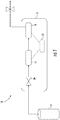
- FIG. 1 illustrates an example of a system for detecting impurities within a refrigerant, namely methyl chloride, the system generally indicated at 10.
- the system 10 includes a refrigerant analyzer 12 in flow communication with a refrigerant vessel 14.
- the refrigerant analyzer 12 includes a first sensing device 16 configured at least to determine a first characteristic of a refrigerant.
- the first characteristic includes a wavelength of electromagnetic energy absorbed by the refrigerant. In one embodiment, the wavelength is less than or equal to approximately 15,500 nanometers.
- the first sensing device 16 is configured to at least detect low concentrations of impurities within the refrigerant. In an embodiment, the first sensing device 16 includes a non-dispersive infrared sensor.
- the refrigerant analyzer 12 further includes a second sensing device 18 in flow communication with the first sensing device 16.
- the second sensing device 18 is configured at least to determine a second characteristic of the refrigerant.
- the second characteristic includes a measured concentration level based at least in part on a sensed electronic output.
- the measured concentration level is greater than or equal to approximately 1000 parts per million, volume based (ppmv).
- the second sensing device 18 includes an electrochemical sensor.
- the refrigerant to be examined can be fed the first sensing device 16 and the second sensing device 18 in parallel as opposed to sequentially as illustrated in FIG. 1 .
- the refrigerant analyzer 12 includes a first flow regulator 20 in flow communication with the first sensing device 16.
- the first flow regulator 20 is configured at least to regulate the flow of refrigerant from the refrigerant vessel 14 through the refrigerant analyzer 12.
- the refrigerant analyzer 12 may further include a processor 22 in electrical communication with the first sensing device 16 and the second sensing device 18.
- the processor 22 is configured to receive data from the first sensing device 16 and the second sensing device 18 and/or generate an alert signal if a contaminant is detected.
- the refrigerant analyzer 12 includes a scrubber 24 in flow communication with the first sensing device 16 and the second sensing device 18.
- the scrubber 24 includes a porous alumina scrubber.
- a scrubber 24 can include a cartridge packed with alumina pellets for adsorption of R40 onto the surface of the pellets.
- Such a cartridge can be reusable, refillable, replaceable or a combination including at least one of the foregoing for ease of use by field technicians.
- the scrubber 24 is configured to selectively remove some impurities within the refrigerant to create distinguishable responses between the first sensing device 16 and the second sensing device 18 for accurate identification and quantification of impurities.
- the refrigerant analyzer 12 includes a second flow regulator 26 in flow communication with the first sensing device 16, , the first flow regulator 20 and the dry scrubber 24.
- the first flow regulator 20 can be configured at least to regulate the flow of refrigerant through the refrigerant analyzer 12.
- the second flow regulator 26 e.g., an automatic 3-way valve to name just one non-limiting example
- FIG. 3 illustrates the first sensing device 16 which can include a sample chamber 28 including a proximal end 30, a distal end 32, an inlet port 34, and an outlet port 36.
- the sample chamber 28 can be configured to allow refrigerant to flow therethrough without changing the composition of the refrigerant.
- a refrigerant may enter the sample chamber 28 through the inlet port 34 and exit through the outlet port 36.
- the first sensing device 16 further includes an infrared lamp 38.
- the infrared lamp 38 may be disposed anywhere within or adjacent to the sample chamber 28.
- the infrared lamp 38 can be located adjacent to the proximal end 30 of the sample chamber 28.
- the infrared lamp 38 may be configured to direct infrared light through the sample chamber 28.
- the first sensing device 16 may further include an optical filter 40.
- the optical filter 40 can be disposed within or adjacent to the sample chamber 28.
- the optical filter 40 can be located adjacent to the distal end 32 of the sample chamber 28.
- the optical filter 40 can be configured to eliminate all light except the wavelength region that selected gas molecules can absorb.
- the optical filter 40 may be configured to transmit a wavelength less than or equal to approximately 15,500 nanometers.
- the optical filter 40 may transmit a wavelength greater than or equal to approximately 13,000 nanometers and less than or equal to approximately 15,000 nanometers.
- the first sensing device 16 further includes a non-dispersive infrared sensor 42.
- the non-dispersive infrared sensor 42 can be disposed adjacent to the optical filter 40 and facing the infrared lamp 38.
- the optical filter 40 can be positioned between the infrared lamp 38 and the non-dispersive infrared sensor 42.
- the non-dispersive infrared sensor 42 can measure the energy of the light from the infrared lamp 38 after it has passed through the refrigerant within the sample chamber 28 and through the optical filter 40. If the non-dispersive infrared sensor 42 detects light within the wavelength range passed by the optical filter 40, this may indicate that the refrigerant within the sample chamber is counterfeit.
- the first sensing device 16 may further include a controller 44 operably coupled to the non-dispersive infrared sensor 42, and the infrared lamp 38.
- the controller 44 can be configured to receive data from the non-dispersive infrared sensor 42 and provide a power signal to the infrared lamp 38.
- the first sensing device 16 can further include a reference chamber 46 disposed adjacent to the sample chamber 28, wherein the reference chamber 46 includes a reference sample disposed therein.
- the reference chamber 46 can be configured to provide a reference for the non-dispersive infrared sensor 42 in order to improve the accuracy of a reading of the refrigerant within the sample chamber 28.
- reference sample may include a refrigerant (e.g., R134a) or air to name a couple of non-limiting examples.
- FIG. 4 illustrates the second sensing device 18.
- the second sensing device 18 includes a membrane electrode assembly (MEA) consisting of a solid polymer electrolyte (SPE) (i.e., ion conducting polymer or ion conducting polymer infiltrated porous matrix) 48 disposed between a sensing electrode 50 and counter electrode 52.
- SPE solid polymer electrolyte
- Current collectors/gas diffusion media 54 and 56 are attached to the electrodes and are connected to circuit 58, which includes a measurement and/or control device 60.
- an optional reference electrode may be in contact with the SPE 48 and electrically connected to measurement and/or control device 60 to enable a compact and integrated multiple sensor device.
- Housing 62 includes openings 64 and 66 for refrigerant to flow therethrough.
- the edges of the MEA are sealed against seal 68 formed of a seal material such as rubber, to name just one non-limiting example.
- the seal 68 ensures that the test gas and reference gas are maintained on opposing sides of the MEA, although other techniques known in the art (e.g., disposing the electrochemical sensor 18 in a frame (not shown) that is sealed to the edges of the housing) can be used.
- the current collectors 54, 56 can be formed from a porous conductive mesh or felt, and are depicted with thickness so that they can also function as gas diffusion media enabling the refrigerant tested and a reference gas (e.g., air) to reach the surface of the electrodes 50, 52.
- the current collector/gas diffusion mediums 54 and 56 associated with the sensing electrode 50 and counter electrode 52, respectively, can be formed from an oxidation-resistant material such as graphitized carbon, titanium, noble metals (e.g. ruthenium, rhodium, palladium, silver, gold, osmium, iridium, platinum and the like), or stainless steel, to name just a few non-limiting examples.
- Measurement and/or control device 60 can include a voltmeter, an ampere meter, a potentiostatic circuit, a microprocessor, an electronic control unit (ECU), or a combination including at least one of the foregoing, or a similar electronic device with integrated voltage and or amperage measurement functions and which can also apply a voltage bias between the sensing electrode 50 and counter electrode 52 during operation of the electrochemical sensor 18.
- ECU electronice control unit
- the second sensing device 18 can further include a sealed chamber 70, which also contains a liquid material such as an aqueous salt or acid solution 72, which can be isolated from contact with the counter electrode 52 by a gas-permeable membrane 74.
- the liquid material is configured to regulate a humidity value within the sealed chamber 70.
- the humidity value may be regulated at a value less than or equal to approximately 60 percent relative humidity.
- FIG. 5 illustrates a schematic flow diagram of a method, generally indicated at 100, for detecting a refrigerant of interest (e.g., a counterfeit refrigerant such as R40 or the like) utilizing the refrigerant analyzer 10.
- the method 100 includes step 102 of circulating a refrigerant through the first sensing device 16 to detect the first characteristic of the refrigerant.
- refrigerant vessel 14 is operably coupled to the refrigerant analyzer 12, and the refrigerant flows from the refrigerant vessel 14 through the first valve 20 into the first sensing device 16.
- the first sensing device 16 operates the non-dispersive infrared sensor 42 to detect energy levels at a wavelength less than or equal to approximately 15,500 nanometers, for example, a wavelength greater than or equal to approximately 13,000 nanometers and less than or equal to approximately 14,400 nanometers.
- controller 44 operates the infrared lamp 38 to shine light through the sample chamber 28.
- Optical filter 40 transmits the wavelengths less than approximately 15,500 nanometers, or in some embodiments wavelength greater than or equal to approximately 13,000 nanometers and less than or equal to approximately 14,400 nanometers.
- the non-dispersive infrared sensor 42 detects the wavelengths that are allowed to pass through optical filter 40. It will be appreciated that wavelengths detected within the range of 13,020 nanometers - 14,400 nanometers are indicative of counterfeit refrigerant R40 present in the refrigerant vessel 14.
- Step 102 includes circulating the refrigerant through a dry scrubber 24.
- the refrigerant is passed through a scrubber 24.
- the refrigerant enters the refrigerant analyzer through the first valve 20, and directed to the scrubber 24, where the scrubber 24 removes some impurities within the refrigerant before circulating through the first sensing device 16.
- the method 100 further includes step 104 of circulating the refrigerant through the second sensing device 18 to detect the second characteristic of the refrigerant.
- the refrigerant continues through the second sensing device 18, where the control device 60 measures a sensed output value, for example a voltage or current at the sensing electrode 54 relative to the counter electrode 56.
- the control device 60 determines a measured concentration of a contaminant within the refrigerant based on the sensed output value.
- the method 100 further includes step 106 of operating the refrigerant analyzer 12 to provide an indication if it is determined that a contaminant is present and its concentration range is estimated using the apparatus and methods disclosed herein.
- the first sensing device 16 and the second sensing device 18 may independently generate a signal indicating the presence of a contaminant.
- the output of the first sensing device 16 and the second sensing device 18 can be analyzed to accurately identify and quantify the impurities, as shown in FIGs. 6 and 7 .
- the first sensing device 16 and the second sensing device 18 may transmit data to the processor 22.
- the processor 22 may analyze the data received by the first sensing device 16 and the second sensing device 18 to determine the presence of a contaminant within the refrigerant.
- FIG. 6 illustrates logic which can be used within the refrigerant analyzer 12.
- the first sensing device 16 and the second sensing device 18 generate a response to the refrigerant having a contaminant within the parameters defined herein.
- the processor 22 may generate a signal indicating the presence of R40.
- the first sensing device 16 generates a response to a contaminant, but the contaminant is undetectable in the second sensing device 18, the processor 22 may generate a signal indicating the presence of R40 or R22 at a concentration level less than 1000 ppmv or a detection limit associated with the second sensing device 18. If the output from Scenario 1 and 2 is deemed inadequate, an embodiment as illustrated in FIG. 2 is employed to identify contaminants. This scheme is illustrated as Scenario 3 in FIG. 7 .
- FIG. 7 illustrates embodiments of the logic within the refrigerant analyzer 12, as shown in FIG. 2 .
- Scenario 2 if the output of first sensing device 16 doesn't provide sufficient resolution to distinguish R40 from R22 based on the absorbance characteristic to these species, additional analysis should be conducted with the assistance of the scrubber 24.
- the determination logic is presented as Scenario 3 in FIG. 7 .
- the processor 22 may generate a signal indicating the presence of both R40 and R22 at a concentration level less than 1000 ppmv.
- the processor 22 may generate a signal indicating the presence of only R22 at a concentration level less than 1000 ppmv or a detection limit associated with the second sensing device 18.
- the processor 22 may generate a signal indicating the presence of an impurity such as R22, R40, or a combination including at least one of the foregoing without indicating a concentration level. In this way, the refrigerant analyzer 12 can provide a binary indication of whether a refrigerant is contaminated with counterfeit refrigerant or not.
- the present embodiments include a refrigerant analyzer 12 combining a highly sensitive first sensing device 16 and a highly selective second sensing device 18 to generate differential responses to enable the detection of contaminants within a refrigerant.
- the highly sensitive first sensing device 16 can detect concentrations of an impurity (e.g. R22, R40, and the like) as low as 10 ppmv, for example concentrations from 10 ppmv to 10,000 ppmv, or 10 ppmv to 2000 ppmv, or 10 ppmv to 1,000 ppmv.
- the highly selective second sensing device 18 can have sensitivity (i.e. signal intensity per unit concentration) to R40 that is infinite times that of other impurities that may be present in a refrigerant sample passing through the refrigerant analyzer 12, for example 2 to 1000 times more sensitive.
Landscapes
- Chemical & Material Sciences (AREA)
- Life Sciences & Earth Sciences (AREA)
- Physics & Mathematics (AREA)
- Health & Medical Sciences (AREA)
- Analytical Chemistry (AREA)
- General Health & Medical Sciences (AREA)
- Pathology (AREA)
- Immunology (AREA)
- General Physics & Mathematics (AREA)
- Biochemistry (AREA)
- Engineering & Computer Science (AREA)
- Spectroscopy & Molecular Physics (AREA)
- Food Science & Technology (AREA)
- Combustion & Propulsion (AREA)
- Medicinal Chemistry (AREA)
- Molecular Biology (AREA)
- Chemical Kinetics & Catalysis (AREA)
- Electrochemistry (AREA)
- Investigating Or Analysing Materials By Optical Means (AREA)
Claims (13)
- Verfahren (100) zum Erfassen von Verunreinigungen in einem Kältemittel unter Verwendung eines Kältemittelanalysators (12), wobei der Kältemittelanalysator (12) eine erste Erfassungsvorrichtung (16) in Strömungsverbindung mit einer zweiten Erfassungsvorrichtung (18) einschließt, wobei das Verfahren Folgendes umfasst:(a) Aufteilen des Kältemittels in einen ersten Kältemittelstrom und einen zweiten Kältemittelstrom und Leiten des ersten Kältemittelstroms durch einen Wäscher (24), während der zweite Kältemittelstrom nicht durch den Wäscher (24) geleitet wird;(b) Leiten des ersten Kältemittelstroms durch die erste Erfassungsvorrichtung (16), um eine erste Eigenschaft des Kältemittels des ersten Kältemittelstroms zu erfassen;(c) Leiten des zweiten Kältemittelstroms durch die erste Erfassungsvorrichtung (16), um eine erste Eigenschaft des Kältemittels des zweiten Kältemittelstroms zu erfassen;(d) Leiten des ersten Kältemittelstroms durch die zweite Erfassungsvorrichtung (18), um eine zweite Eigenschaft des Kältemittels des ersten Kältemittelstroms zu erfassen;(e) Leiten des zweiten Kältemittelstroms durch die zweite Erfassungsvorrichtung (18), um eine zweite Eigenschaft des Kältemittels des zweiten Kältemittelstroms zu erfassen;
wobei die erste Erfassungsvorrichtung (16) einen nicht dispersiven Infrarotsensor umfasst und die zweite Erfassungsvorrichtung (18) einen elektrochemischen Sensor umfasst; und(f) Ermitteln der Anwesenheit einer Verunreinigung in dem Kältemittel auf der Grundlage der Eigenschaften, die in den Schritten (b) bis (e) ermittelt wurden. - Verfahren (100) nach Anspruch 1, wobei die erste Eigenschaft die Absorption einer Lichtwellenlänge des Kältemittels umfasst.
- Verfahren (100) nach einem der vorhergehenden Ansprüche, wobei die erste Eigenschaft die Absorption einer Lichtwellenlänge des Kältemittels umfasst und die Wellenlänge weniger oder gleich 15,500 Nanometern entspricht.
- Verfahren (100) nach einem der vorhergehenden Ansprüche, wobei die zweite Eigenschaft ein gemessenes Konzentrationslevel umfasst, das mindestens teilweise auf Grundlage einer erfassten Ausgabe der zweiten Erfassungsvorrichtung (18) beruht.
- Verfahren nach einem der vorhergehenden Ansprüche, wobei die zweite Eigenschaft ein gemessenes Konzentrationslevel umfasst, das mindestens teilweise auf Grundlage einer erfassten Ausgabe der zweiten Erfassungsvorrichtung (18) beruht und das gemessene Konzentrationslevel größer oder gleich 1000 ppmv ist.
- Verfahren (100) nach einem der vorhergehenden Ansprüche, ferner umfassend:
(g) Betreiben des Kältemittelanalysators (12), um einen Hinweis bereitzustellen, wenn ermittelt wird, dass eine Verunreinigung vorliegt. - Kältemittelanalysator (12), der Folgendes umfasst:einen Wäscher (24); eine erste Erfassungsvorrichtung (16); einen Strömungsregler (26), der operabel mit dem Wäscher (24) und der ersten Erfassungsvorrichtung (16) verbunden ist, wobei der Durchflussregler (26) dazu konfiguriert ist, einen ersten Kältemittelstrom und einen zweiten Kältemittelstrom herzustellen, und wobei die erste Erfassungsvorrichtung (16) dazu konfiguriert ist, mindestens eine erste Eigenschaft eines Kältemittels des ersten Kältemittelstroms und des zweiten Kältemittelstroms zu ermitteln;eine zweite Erfassungsvorrichtung (18) in Strömungsverbindung mit der ersten Erfassungsvorrichtung (16), wobei die zweite Erfassungsvorrichtung (18) dazu konfiguriert ist, mindestens eine zweite Eigenschaft des Kältemittels des ersten und zweiten Kältemittelstroms zu bestimmen;wobei der erste Kältemittelstrom durch den Wäscher (24) geleitet wird und der zweite Kältemittelstrom nicht durch den Wäscher (24) geleitet wird; undwobei die erste Erfassungsvorrichtung (16) einen nicht dispersiven Infrarotsensor umfasst; unddie zweite Erfassungsvorrichtung (18) einen elektrochemischen Sensor umfasst.
- Kältemittelanalysator (12) nach Anspruch 7, ferner umfassend einen Prozessor (22) in elektrischer Verbindung mit der ersten Erfassungsvorrichtung (16) und der zweiten Erfassungsvorrichtung (18).
- Kältemittelanalysator (12) nach Anspruch 7 oder 8, wobei die erste Eigenschaft die Absorption einer Lichtwellenlänge durch das Kältemittel umfasst.
- Kältemittelanalysator (12) nach Anspruch 9, wobei die erste Eigenschaft die Absorption einer Lichtwellenlänge durch das Kältemittel umfasst und die Wellenlänge kleiner oder gleich 15.500 Nanometer ist.
- Kältemittelanalysator (12) nach einem der Ansprüche 7-10, wobei die zweite Eigenschaft ein gemessenes Konzentrationslevel umfasst, das mindestens teilweise auf Grundlage einer erfassten Ausgabe der zweiten Erfassungsvorrichtung (18) beruht.
- Kältemittelanalysator (12) nach Anspruch 11, wobei das gemessene Konzentrationslevel größer oder gleich 1000 ppmv ist.
- Kältemittelanalysator (12) nach einem der Ansprüche 7-12, wobei der Wäscher (24) fluidisch stromaufwärts von der ersten Erfassungsvorrichtung (16) liegt oder wobei der Wäscher (24) fluidisch stromaufwärts von der zweiten Erfassungsvorrichtung (18) liegt.
Applications Claiming Priority (2)
| Application Number | Priority Date | Filing Date | Title |
|---|---|---|---|
| US201562197778P | 2015-07-28 | 2015-07-28 | |
| PCT/US2016/044578 WO2017019909A1 (en) | 2015-07-28 | 2016-07-28 | Refrigerant analyzer and a method of using the same |
Publications (2)
| Publication Number | Publication Date |
|---|---|
| EP3329264A1 EP3329264A1 (de) | 2018-06-06 |
| EP3329264B1 true EP3329264B1 (de) | 2020-01-29 |
Family
ID=56800356
Family Applications (1)
| Application Number | Title | Priority Date | Filing Date |
|---|---|---|---|
| EP16757106.6A Active EP3329264B1 (de) | 2015-07-28 | 2016-07-28 | Kältemittelanalysator und verfahren zu dessen verwendung |
Country Status (6)
| Country | Link |
|---|---|
| US (1) | US10663396B2 (de) |
| EP (1) | EP3329264B1 (de) |
| JP (1) | JP6847092B2 (de) |
| CN (1) | CN108139348B (de) |
| DK (1) | DK3329264T3 (de) |
| WO (1) | WO2017019909A1 (de) |
Families Citing this family (2)
| Publication number | Priority date | Publication date | Assignee | Title |
|---|---|---|---|---|
| ES2951572T3 (es) | 2017-05-12 | 2023-10-24 | Carrier Corp | Sensor y método para la prueba de gas |
| US11408624B2 (en) * | 2019-10-15 | 2022-08-09 | Carrier Corporation | Refrigerant leak detection |
Family Cites Families (30)
| Publication number | Priority date | Publication date | Assignee | Title |
|---|---|---|---|---|
| US1864544A (en) | 1929-10-01 | 1932-06-28 | Arthur B Lamb | Device for detecting methyl chloride |
| US4670405A (en) | 1984-03-02 | 1987-06-02 | The United States Of America As Represented By The United States Department Of Energy | Sensor array for toxic gas detection |
| DE3819128C2 (de) | 1988-06-04 | 1995-10-26 | Conducta Endress & Hauser | Gasdetektionssystem |
| IE63294B1 (en) | 1990-01-16 | 1995-04-05 | Iaws Res Ltd | Apparatus for placing granular or the like material in one or more receptacles |
| US5184015A (en) | 1991-09-27 | 1993-02-02 | Martin Marietta Energy Systems, Inc. | Charged particle mobility refrigerant analyzer |
| US5363661A (en) * | 1993-09-03 | 1994-11-15 | Condit David A | Method and apparatus for testing refrigerant |
| FR2710153B1 (fr) | 1993-09-17 | 1995-12-01 | Alpha Mos Sa | Procédés et appareils de détection des substances odorantes et applications. |
| US5511409A (en) * | 1994-09-19 | 1996-04-30 | Knaebel; Kent S. | Measurement of emission levels in a gas stream |
| GB9512929D0 (en) | 1995-06-24 | 1995-08-30 | Sun Electric Uk Ltd | Multi-gas sensor systems for automatic emissions measurement |
| US6085576A (en) | 1998-03-20 | 2000-07-11 | Cyrano Sciences, Inc. | Handheld sensing apparatus |
| US6670613B2 (en) | 2000-04-28 | 2003-12-30 | Bacharach, Inc. | System and method for spectral analysis |
| JP2002032870A (ja) * | 2000-07-19 | 2002-01-31 | Central Glass Co Ltd | 複層ガラスを使用した防犯システム |
| US20040024278A1 (en) | 2001-10-26 | 2004-02-05 | Lockheed Martin Corp., A Maryland Corporation | Single station hazardous material detection and neutralization system for letters and packages |
| US20040022670A1 (en) | 2001-10-31 | 2004-02-05 | Lockheed Martin Corp., A Maryland Corporation | System and method for decontaminating and/or sanitizing mail |
| JP3762729B2 (ja) * | 2002-09-11 | 2006-04-05 | 株式会社堀場製作所 | 多成分分析装置 |
| EP1398618A3 (de) * | 2002-09-11 | 2004-07-28 | Horiba, Ltd. | Analysevorrichtung für mehrere Komponenten |
| JP2004138453A (ja) * | 2002-10-16 | 2004-05-13 | Horiba Ltd | 混合冷媒分析装置 |
| US20050211949A1 (en) * | 2003-11-13 | 2005-09-29 | Bivens Donald B | Detectable refrigerant compositions and uses thereof |
| US7140229B2 (en) | 2004-06-29 | 2006-11-28 | Mst Technology Gmbh | Gas-monitoring assembly comprising one or more gas sensors and one or more getters, and method of using same |
| US7756683B2 (en) | 2004-07-12 | 2010-07-13 | MLU-Monitoring fuer Leben und Umwelt GES.m.b.H. | Measuring device and method for measuring at least one environmental parameter |
| AU2008240146B2 (en) | 2007-04-11 | 2013-10-17 | Spectrasensors, Inc. | Reactive gas detection in complex backgrounds |
| JP2009198154A (ja) * | 2007-10-23 | 2009-09-03 | Daikin Ind Ltd | 流体センサ、冷媒漏洩検知装置、冷凍装置、及び、冷媒漏洩検知方法 |
| KR20110063442A (ko) | 2008-09-03 | 2011-06-10 | 테스토 아게 | 측정값 감지 및 측정값 표시를 위한 방법 |
| EP2388581A1 (de) | 2010-05-17 | 2011-11-23 | Airsense Analytics GmbH | Vorrichtung und Verfahren zur Detektion von Gefahrstoffen mit wenigstens zwei an eine Auswerteeinheit verbundenen austauschbaren Sensorelementen |
| US8692997B2 (en) * | 2010-08-25 | 2014-04-08 | Bah Holdings Llc | Optical gas and/or particulate sensors |
| WO2013066316A1 (en) * | 2011-11-01 | 2013-05-10 | Draeger Safety, Inc. | Detection of gas mixtures having an additive or synergistic toxic effect |
| US9074731B2 (en) | 2011-12-15 | 2015-07-07 | Venture Corporation Limited | Gas monitoring system with oxygen control for human life support in enclosed refuge spaces |
| CN203178248U (zh) | 2013-03-06 | 2013-09-04 | 杨宗辉 | 家用电器碳氢化合物制冷剂释放及低爆炸极限测量装置 |
| WO2016029005A1 (en) * | 2014-08-20 | 2016-02-25 | Carrier Corporation | Detection of refrigerant contaminants |
| EP3237885A1 (de) * | 2014-12-23 | 2017-11-01 | Carrier Corporation | Analysator für kältemittelnachahmung |
-
2016
- 2016-07-28 CN CN201680044380.6A patent/CN108139348B/zh active Active
- 2016-07-28 JP JP2018504127A patent/JP6847092B2/ja active Active
- 2016-07-28 DK DK16757106.6T patent/DK3329264T3/da active
- 2016-07-28 US US15/748,112 patent/US10663396B2/en active Active
- 2016-07-28 EP EP16757106.6A patent/EP3329264B1/de active Active
- 2016-07-28 WO PCT/US2016/044578 patent/WO2017019909A1/en not_active Ceased
Non-Patent Citations (1)
| Title |
|---|
| None * |
Also Published As
| Publication number | Publication date |
|---|---|
| WO2017019909A1 (en) | 2017-02-02 |
| CN108139348B (zh) | 2021-09-17 |
| DK3329264T3 (da) | 2020-03-09 |
| EP3329264A1 (de) | 2018-06-06 |
| JP6847092B2 (ja) | 2021-03-24 |
| US10663396B2 (en) | 2020-05-26 |
| JP2018529936A (ja) | 2018-10-11 |
| CN108139348A (zh) | 2018-06-08 |
| US20180356337A1 (en) | 2018-12-13 |
Similar Documents
| Publication | Publication Date | Title |
|---|---|---|
| EP3430319B1 (de) | Luftreiniger und luftreinigungsverfahren | |
| US4670405A (en) | Sensor array for toxic gas detection | |
| US4888295A (en) | Portable system and method combining chromatography and array of electrochemical sensors | |
| US6165347A (en) | Method of identifying a gas | |
| EP3329264B1 (de) | Kältemittelanalysator und verfahren zu dessen verwendung | |
| US6661233B2 (en) | Gas analyzer with real-time broadband monitoring and snapshot selective detection | |
| EP3254097B1 (de) | Kältemittelanalysator und verfahren zur verwendung davon | |
| RU2643926C2 (ru) | Способ детектирования взрывчатых веществ (вв) в воздухе | |
| KR20010039446A (ko) | 변압기 이상 감시장치 | |
| CN115436443B (zh) | 气体暴露剂量检测装置及方法 | |
| CN210572098U (zh) | 用于测量气体中油蒸汽或其它烃类含量的测量装置 | |
| CN115326899B (zh) | 气体检测装置及气体浓度检测方法 | |
| CN113984756A (zh) | 一种水环境中重金属的检测装置及其方法 | |
| Li et al. | An On-Line Monitoring System for Nitrate in Seawater Based on UV Spectrum | |
| Dan et al. | An on-line monitoring system for nitrate in seawater based on UV spectrum | |
| Hori et al. | Development of a new respirator for organic vapors with a breakthrough detector using a semiconductor gas sensor | |
| JP3873492B2 (ja) | ガス測定装置 | |
| Liu et al. | Gas-permeation continuous flow coulometric analysis: determination of sulphur dioxide | |
| CN121275669A (zh) | 一种溶液中贵金属浓度快速检测的方法 | |
| JP2004125579A (ja) | におい測定装置 | |
| Herrick et al. | Sulfur Oxide Analyzers | |
| LIU et al. | 8.26 Hydrogen Sulfide |
Legal Events
| Date | Code | Title | Description |
|---|---|---|---|
| STAA | Information on the status of an ep patent application or granted ep patent |
Free format text: STATUS: UNKNOWN |
|
| STAA | Information on the status of an ep patent application or granted ep patent |
Free format text: STATUS: THE INTERNATIONAL PUBLICATION HAS BEEN MADE |
|
| PUAI | Public reference made under article 153(3) epc to a published international application that has entered the european phase |
Free format text: ORIGINAL CODE: 0009012 |
|
| STAA | Information on the status of an ep patent application or granted ep patent |
Free format text: STATUS: REQUEST FOR EXAMINATION WAS MADE |
|
| 17P | Request for examination filed |
Effective date: 20180220 |
|
| AK | Designated contracting states |
Kind code of ref document: A1 Designated state(s): AL AT BE BG CH CY CZ DE DK EE ES FI FR GB GR HR HU IE IS IT LI LT LU LV MC MK MT NL NO PL PT RO RS SE SI SK SM TR |
|
| AX | Request for extension of the european patent |
Extension state: BA ME |
|
| RIN1 | Information on inventor provided before grant (corrected) |
Inventor name: YANG, ZHIWEI Inventor name: CLOUGH, WARREN Inventor name: POSTGATE, FARLEY, WILLIAM Inventor name: RYDKIN, IVAN Inventor name: CHEN, LEI |
|
| DAV | Request for validation of the european patent (deleted) | ||
| DAX | Request for extension of the european patent (deleted) | ||
| STAA | Information on the status of an ep patent application or granted ep patent |
Free format text: STATUS: EXAMINATION IS IN PROGRESS |
|
| 17Q | First examination report despatched |
Effective date: 20190103 |
|
| GRAP | Despatch of communication of intention to grant a patent |
Free format text: ORIGINAL CODE: EPIDOSNIGR1 |
|
| STAA | Information on the status of an ep patent application or granted ep patent |
Free format text: STATUS: GRANT OF PATENT IS INTENDED |
|
| RIC1 | Information provided on ipc code assigned before grant |
Ipc: G01N 27/27 20060101AFI20190802BHEP Ipc: G01N 33/00 20060101ALI20190802BHEP Ipc: G01N 27/407 20060101ALN20190802BHEP Ipc: G01N 21/3504 20140101ALI20190802BHEP Ipc: G01N 21/94 20060101ALN20190802BHEP Ipc: G01N 21/61 20060101ALN20190802BHEP |
|
| RIC1 | Information provided on ipc code assigned before grant |
Ipc: G01N 27/407 20060101ALN20190821BHEP Ipc: G01N 21/3504 20140101ALI20190821BHEP Ipc: G01N 27/27 20060101AFI20190821BHEP Ipc: G01N 33/00 20060101ALI20190821BHEP Ipc: G01N 21/61 20060101ALN20190821BHEP Ipc: G01N 21/94 20060101ALN20190821BHEP |
|
| INTG | Intention to grant announced |
Effective date: 20190903 |
|
| GRAJ | Information related to disapproval of communication of intention to grant by the applicant or resumption of examination proceedings by the epo deleted |
Free format text: ORIGINAL CODE: EPIDOSDIGR1 |
|
| STAA | Information on the status of an ep patent application or granted ep patent |
Free format text: STATUS: EXAMINATION IS IN PROGRESS |
|
| GRAP | Despatch of communication of intention to grant a patent |
Free format text: ORIGINAL CODE: EPIDOSNIGR1 |
|
| STAA | Information on the status of an ep patent application or granted ep patent |
Free format text: STATUS: GRANT OF PATENT IS INTENDED |
|
| INTC | Intention to grant announced (deleted) | ||
| GRAS | Grant fee paid |
Free format text: ORIGINAL CODE: EPIDOSNIGR3 |
|
| RIC1 | Information provided on ipc code assigned before grant |
Ipc: G01N 21/61 20060101ALN20191121BHEP Ipc: G01N 21/3504 20140101ALI20191121BHEP Ipc: G01N 33/00 20060101ALI20191121BHEP Ipc: G01N 27/27 20060101AFI20191121BHEP Ipc: G01N 27/407 20060101ALN20191121BHEP Ipc: G01N 21/94 20060101ALN20191121BHEP |
|
| GRAA | (expected) grant |
Free format text: ORIGINAL CODE: 0009210 |
|
| STAA | Information on the status of an ep patent application or granted ep patent |
Free format text: STATUS: THE PATENT HAS BEEN GRANTED |
|
| INTG | Intention to grant announced |
Effective date: 20191210 |
|
| AK | Designated contracting states |
Kind code of ref document: B1 Designated state(s): AL AT BE BG CH CY CZ DE DK EE ES FI FR GB GR HR HU IE IS IT LI LT LU LV MC MK MT NL NO PL PT RO RS SE SI SK SM TR |
|
| REG | Reference to a national code |
Ref country code: GB Ref legal event code: FG4D |
|
| REG | Reference to a national code |
Ref country code: CH Ref legal event code: EP |
|
| REG | Reference to a national code |
Ref country code: AT Ref legal event code: REF Ref document number: 1228856 Country of ref document: AT Kind code of ref document: T Effective date: 20200215 |
|
| REG | Reference to a national code |
Ref country code: IE Ref legal event code: FG4D |
|
| REG | Reference to a national code |
Ref country code: DE Ref legal event code: R096 Ref document number: 602016028768 Country of ref document: DE |
|
| REG | Reference to a national code |
Ref country code: DK Ref legal event code: T3 Effective date: 20200302 |
|
| REG | Reference to a national code |
Ref country code: CH Ref legal event code: NV Representative=s name: VALIPAT S.A. C/O BOVARD SA NEUCHATEL, CH |
|
| REG | Reference to a national code |
Ref country code: NL Ref legal event code: MP Effective date: 20200129 |
|
| PG25 | Lapsed in a contracting state [announced via postgrant information from national office to epo] |
Ref country code: PT Free format text: LAPSE BECAUSE OF FAILURE TO SUBMIT A TRANSLATION OF THE DESCRIPTION OR TO PAY THE FEE WITHIN THE PRESCRIBED TIME-LIMIT Effective date: 20200621 Ref country code: RS Free format text: LAPSE BECAUSE OF FAILURE TO SUBMIT A TRANSLATION OF THE DESCRIPTION OR TO PAY THE FEE WITHIN THE PRESCRIBED TIME-LIMIT Effective date: 20200129 Ref country code: FI Free format text: LAPSE BECAUSE OF FAILURE TO SUBMIT A TRANSLATION OF THE DESCRIPTION OR TO PAY THE FEE WITHIN THE PRESCRIBED TIME-LIMIT Effective date: 20200129 Ref country code: NO Free format text: LAPSE BECAUSE OF FAILURE TO SUBMIT A TRANSLATION OF THE DESCRIPTION OR TO PAY THE FEE WITHIN THE PRESCRIBED TIME-LIMIT Effective date: 20200429 |
|
| REG | Reference to a national code |
Ref country code: LT Ref legal event code: MG4D |
|
| PG25 | Lapsed in a contracting state [announced via postgrant information from national office to epo] |
Ref country code: GR Free format text: LAPSE BECAUSE OF FAILURE TO SUBMIT A TRANSLATION OF THE DESCRIPTION OR TO PAY THE FEE WITHIN THE PRESCRIBED TIME-LIMIT Effective date: 20200430 Ref country code: IS Free format text: LAPSE BECAUSE OF FAILURE TO SUBMIT A TRANSLATION OF THE DESCRIPTION OR TO PAY THE FEE WITHIN THE PRESCRIBED TIME-LIMIT Effective date: 20200529 Ref country code: LV Free format text: LAPSE BECAUSE OF FAILURE TO SUBMIT A TRANSLATION OF THE DESCRIPTION OR TO PAY THE FEE WITHIN THE PRESCRIBED TIME-LIMIT Effective date: 20200129 Ref country code: SE Free format text: LAPSE BECAUSE OF FAILURE TO SUBMIT A TRANSLATION OF THE DESCRIPTION OR TO PAY THE FEE WITHIN THE PRESCRIBED TIME-LIMIT Effective date: 20200129 Ref country code: BG Free format text: LAPSE BECAUSE OF FAILURE TO SUBMIT A TRANSLATION OF THE DESCRIPTION OR TO PAY THE FEE WITHIN THE PRESCRIBED TIME-LIMIT Effective date: 20200429 Ref country code: HR Free format text: LAPSE BECAUSE OF FAILURE TO SUBMIT A TRANSLATION OF THE DESCRIPTION OR TO PAY THE FEE WITHIN THE PRESCRIBED TIME-LIMIT Effective date: 20200129 |
|
| PG25 | Lapsed in a contracting state [announced via postgrant information from national office to epo] |
Ref country code: NL Free format text: LAPSE BECAUSE OF FAILURE TO SUBMIT A TRANSLATION OF THE DESCRIPTION OR TO PAY THE FEE WITHIN THE PRESCRIBED TIME-LIMIT Effective date: 20200129 |
|
| PG25 | Lapsed in a contracting state [announced via postgrant information from national office to epo] |
Ref country code: LT Free format text: LAPSE BECAUSE OF FAILURE TO SUBMIT A TRANSLATION OF THE DESCRIPTION OR TO PAY THE FEE WITHIN THE PRESCRIBED TIME-LIMIT Effective date: 20200129 Ref country code: SM Free format text: LAPSE BECAUSE OF FAILURE TO SUBMIT A TRANSLATION OF THE DESCRIPTION OR TO PAY THE FEE WITHIN THE PRESCRIBED TIME-LIMIT Effective date: 20200129 Ref country code: EE Free format text: LAPSE BECAUSE OF FAILURE TO SUBMIT A TRANSLATION OF THE DESCRIPTION OR TO PAY THE FEE WITHIN THE PRESCRIBED TIME-LIMIT Effective date: 20200129 Ref country code: SK Free format text: LAPSE BECAUSE OF FAILURE TO SUBMIT A TRANSLATION OF THE DESCRIPTION OR TO PAY THE FEE WITHIN THE PRESCRIBED TIME-LIMIT Effective date: 20200129 Ref country code: CZ Free format text: LAPSE BECAUSE OF FAILURE TO SUBMIT A TRANSLATION OF THE DESCRIPTION OR TO PAY THE FEE WITHIN THE PRESCRIBED TIME-LIMIT Effective date: 20200129 Ref country code: ES Free format text: LAPSE BECAUSE OF FAILURE TO SUBMIT A TRANSLATION OF THE DESCRIPTION OR TO PAY THE FEE WITHIN THE PRESCRIBED TIME-LIMIT Effective date: 20200129 Ref country code: RO Free format text: LAPSE BECAUSE OF FAILURE TO SUBMIT A TRANSLATION OF THE DESCRIPTION OR TO PAY THE FEE WITHIN THE PRESCRIBED TIME-LIMIT Effective date: 20200129 |
|
| REG | Reference to a national code |
Ref country code: DE Ref legal event code: R097 Ref document number: 602016028768 Country of ref document: DE |
|
| REG | Reference to a national code |
Ref country code: AT Ref legal event code: MK05 Ref document number: 1228856 Country of ref document: AT Kind code of ref document: T Effective date: 20200129 |
|
| PLBE | No opposition filed within time limit |
Free format text: ORIGINAL CODE: 0009261 |
|
| STAA | Information on the status of an ep patent application or granted ep patent |
Free format text: STATUS: NO OPPOSITION FILED WITHIN TIME LIMIT |
|
| 26N | No opposition filed |
Effective date: 20201030 |
|
| PG25 | Lapsed in a contracting state [announced via postgrant information from national office to epo] |
Ref country code: IT Free format text: LAPSE BECAUSE OF FAILURE TO SUBMIT A TRANSLATION OF THE DESCRIPTION OR TO PAY THE FEE WITHIN THE PRESCRIBED TIME-LIMIT Effective date: 20200129 Ref country code: AT Free format text: LAPSE BECAUSE OF FAILURE TO SUBMIT A TRANSLATION OF THE DESCRIPTION OR TO PAY THE FEE WITHIN THE PRESCRIBED TIME-LIMIT Effective date: 20200129 |
|
| PG25 | Lapsed in a contracting state [announced via postgrant information from national office to epo] |
Ref country code: SI Free format text: LAPSE BECAUSE OF FAILURE TO SUBMIT A TRANSLATION OF THE DESCRIPTION OR TO PAY THE FEE WITHIN THE PRESCRIBED TIME-LIMIT Effective date: 20200129 Ref country code: PL Free format text: LAPSE BECAUSE OF FAILURE TO SUBMIT A TRANSLATION OF THE DESCRIPTION OR TO PAY THE FEE WITHIN THE PRESCRIBED TIME-LIMIT Effective date: 20200129 Ref country code: MC Free format text: LAPSE BECAUSE OF FAILURE TO SUBMIT A TRANSLATION OF THE DESCRIPTION OR TO PAY THE FEE WITHIN THE PRESCRIBED TIME-LIMIT Effective date: 20200129 |
|
| REG | Reference to a national code |
Ref country code: BE Ref legal event code: MM Effective date: 20200731 |
|
| PG25 | Lapsed in a contracting state [announced via postgrant information from national office to epo] |
Ref country code: LU Free format text: LAPSE BECAUSE OF NON-PAYMENT OF DUE FEES Effective date: 20200728 |
|
| PG25 | Lapsed in a contracting state [announced via postgrant information from national office to epo] |
Ref country code: BE Free format text: LAPSE BECAUSE OF NON-PAYMENT OF DUE FEES Effective date: 20200731 |
|
| PG25 | Lapsed in a contracting state [announced via postgrant information from national office to epo] |
Ref country code: IE Free format text: LAPSE BECAUSE OF NON-PAYMENT OF DUE FEES Effective date: 20200728 |
|
| PGFP | Annual fee paid to national office [announced via postgrant information from national office to epo] |
Ref country code: CH Payment date: 20210622 Year of fee payment: 6 |
|
| PG25 | Lapsed in a contracting state [announced via postgrant information from national office to epo] |
Ref country code: TR Free format text: LAPSE BECAUSE OF FAILURE TO SUBMIT A TRANSLATION OF THE DESCRIPTION OR TO PAY THE FEE WITHIN THE PRESCRIBED TIME-LIMIT Effective date: 20200129 Ref country code: MT Free format text: LAPSE BECAUSE OF FAILURE TO SUBMIT A TRANSLATION OF THE DESCRIPTION OR TO PAY THE FEE WITHIN THE PRESCRIBED TIME-LIMIT Effective date: 20200129 Ref country code: CY Free format text: LAPSE BECAUSE OF FAILURE TO SUBMIT A TRANSLATION OF THE DESCRIPTION OR TO PAY THE FEE WITHIN THE PRESCRIBED TIME-LIMIT Effective date: 20200129 |
|
| PG25 | Lapsed in a contracting state [announced via postgrant information from national office to epo] |
Ref country code: MK Free format text: LAPSE BECAUSE OF FAILURE TO SUBMIT A TRANSLATION OF THE DESCRIPTION OR TO PAY THE FEE WITHIN THE PRESCRIBED TIME-LIMIT Effective date: 20200129 Ref country code: AL Free format text: LAPSE BECAUSE OF FAILURE TO SUBMIT A TRANSLATION OF THE DESCRIPTION OR TO PAY THE FEE WITHIN THE PRESCRIBED TIME-LIMIT Effective date: 20200129 |
|
| REG | Reference to a national code |
Ref country code: CH Ref legal event code: PL |
|
| PG25 | Lapsed in a contracting state [announced via postgrant information from national office to epo] |
Ref country code: LI Free format text: LAPSE BECAUSE OF NON-PAYMENT OF DUE FEES Effective date: 20220731 Ref country code: CH Free format text: LAPSE BECAUSE OF NON-PAYMENT OF DUE FEES Effective date: 20220731 |
|
| PGFP | Annual fee paid to national office [announced via postgrant information from national office to epo] |
Ref country code: DK Payment date: 20230622 Year of fee payment: 8 |
|
| PGFP | Annual fee paid to national office [announced via postgrant information from national office to epo] |
Ref country code: DE Payment date: 20240619 Year of fee payment: 9 |
|
| REG | Reference to a national code |
Ref country code: DK Ref legal event code: EBP Effective date: 20240731 |
|
| PG25 | Lapsed in a contracting state [announced via postgrant information from national office to epo] |
Ref country code: DK Free format text: LAPSE BECAUSE OF NON-PAYMENT OF DUE FEES Effective date: 20240731 |
|
| PGFP | Annual fee paid to national office [announced via postgrant information from national office to epo] |
Ref country code: GB Payment date: 20250619 Year of fee payment: 10 |
|
| PGFP | Annual fee paid to national office [announced via postgrant information from national office to epo] |
Ref country code: FR Payment date: 20250620 Year of fee payment: 10 |
|
| REG | Reference to a national code |
Ref country code: DE Ref legal event code: R119 Ref document number: 602016028768 Country of ref document: DE |
|
| PG25 | Lapsed in a contracting state [announced via postgrant information from national office to epo] |
Ref country code: DE Free format text: LAPSE BECAUSE OF NON-PAYMENT OF DUE FEES Effective date: 20260203 |