EP3329559B1 - Connecteur électrique enfichable à pont de court-circuitage résistant aux vibrations et connexion électrique enfichable - Google Patents
Connecteur électrique enfichable à pont de court-circuitage résistant aux vibrations et connexion électrique enfichable Download PDFInfo
- Publication number
- EP3329559B1 EP3329559B1 EP16747761.1A EP16747761A EP3329559B1 EP 3329559 B1 EP3329559 B1 EP 3329559B1 EP 16747761 A EP16747761 A EP 16747761A EP 3329559 B1 EP3329559 B1 EP 3329559B1
- Authority
- EP
- European Patent Office
- Prior art keywords
- short
- plug connector
- circuiting
- circuiting bridge
- bridge
- Prior art date
- Legal status (The legal status is an assumption and is not a legal conclusion. Google has not performed a legal analysis and makes no representation as to the accuracy of the status listed.)
- Active
Links
Images



Classifications
-
- H—ELECTRICITY
- H01—ELECTRIC ELEMENTS
- H01R—ELECTRICALLY-CONDUCTIVE CONNECTIONS; STRUCTURAL ASSOCIATIONS OF A PLURALITY OF MUTUALLY-INSULATED ELECTRICAL CONNECTING ELEMENTS; COUPLING DEVICES; CURRENT COLLECTORS
- H01R13/00—Details of coupling devices of the kinds covered by groups H01R12/70 or H01R24/00 - H01R33/00
- H01R13/64—Means for preventing incorrect coupling
- H01R13/641—Means for preventing incorrect coupling by indicating incorrect coupling; by indicating correct or full engagement
-
- H—ELECTRICITY
- H01—ELECTRIC ELEMENTS
- H01R—ELECTRICALLY-CONDUCTIVE CONNECTIONS; STRUCTURAL ASSOCIATIONS OF A PLURALITY OF MUTUALLY-INSULATED ELECTRICAL CONNECTING ELEMENTS; COUPLING DEVICES; CURRENT COLLECTORS
- H01R13/00—Details of coupling devices of the kinds covered by groups H01R12/70 or H01R24/00 - H01R33/00
- H01R13/62—Means for facilitating engagement or disengagement of coupling parts or for holding them in engagement
- H01R13/627—Snap or like fastening
- H01R13/6271—Latching means integral with the housing
-
- H—ELECTRICITY
- H01—ELECTRIC ELEMENTS
- H01R—ELECTRICALLY-CONDUCTIVE CONNECTIONS; STRUCTURAL ASSOCIATIONS OF A PLURALITY OF MUTUALLY-INSULATED ELECTRICAL CONNECTING ELEMENTS; COUPLING DEVICES; CURRENT COLLECTORS
- H01R13/00—Details of coupling devices of the kinds covered by groups H01R12/70 or H01R24/00 - H01R33/00
- H01R13/66—Structural association with built-in electrical component
- H01R13/70—Structural association with built-in electrical component with built-in switch
- H01R13/707—Structural association with built-in electrical component with built-in switch interlocked with contact members or counterpart
-
- H—ELECTRICITY
- H01—ELECTRIC ELEMENTS
- H01R—ELECTRICALLY-CONDUCTIVE CONNECTIONS; STRUCTURAL ASSOCIATIONS OF A PLURALITY OF MUTUALLY-INSULATED ELECTRICAL CONNECTING ELEMENTS; COUPLING DEVICES; CURRENT COLLECTORS
- H01R31/00—Coupling parts supported only by co-operation with counterpart
- H01R31/08—Short-circuiting members for bridging contacts in a counterpart
-
- H—ELECTRICITY
- H01—ELECTRIC ELEMENTS
- H01R—ELECTRICALLY-CONDUCTIVE CONNECTIONS; STRUCTURAL ASSOCIATIONS OF A PLURALITY OF MUTUALLY-INSULATED ELECTRICAL CONNECTING ELEMENTS; COUPLING DEVICES; CURRENT COLLECTORS
- H01R13/00—Details of coupling devices of the kinds covered by groups H01R12/70 or H01R24/00 - H01R33/00
- H01R13/62—Means for facilitating engagement or disengagement of coupling parts or for holding them in engagement
- H01R13/629—Additional means for facilitating engagement or disengagement of coupling parts, e.g. aligning or guiding means, levers, gas pressure electrical locking indicators, manufacturing tolerances
- H01R13/631—Additional means for facilitating engagement or disengagement of coupling parts, e.g. aligning or guiding means, levers, gas pressure electrical locking indicators, manufacturing tolerances for engagement only
- H01R13/6315—Additional means for facilitating engagement or disengagement of coupling parts, e.g. aligning or guiding means, levers, gas pressure electrical locking indicators, manufacturing tolerances for engagement only allowing relative movement between coupling parts, e.g. floating connection
-
- H—ELECTRICITY
- H01—ELECTRIC ELEMENTS
- H01R—ELECTRICALLY-CONDUCTIVE CONNECTIONS; STRUCTURAL ASSOCIATIONS OF A PLURALITY OF MUTUALLY-INSULATED ELECTRICAL CONNECTING ELEMENTS; COUPLING DEVICES; CURRENT COLLECTORS
- H01R13/00—Details of coupling devices of the kinds covered by groups H01R12/70 or H01R24/00 - H01R33/00
- H01R13/64—Means for preventing incorrect coupling
- H01R13/645—Means for preventing incorrect coupling by exchangeable elements on case or base
-
- H—ELECTRICITY
- H01—ELECTRIC ELEMENTS
- H01R—ELECTRICALLY-CONDUCTIVE CONNECTIONS; STRUCTURAL ASSOCIATIONS OF A PLURALITY OF MUTUALLY-INSULATED ELECTRICAL CONNECTING ELEMENTS; COUPLING DEVICES; CURRENT COLLECTORS
- H01R2103/00—Two poles
-
- H—ELECTRICITY
- H01—ELECTRIC ELEMENTS
- H01R—ELECTRICALLY-CONDUCTIVE CONNECTIONS; STRUCTURAL ASSOCIATIONS OF A PLURALITY OF MUTUALLY-INSULATED ELECTRICAL CONNECTING ELEMENTS; COUPLING DEVICES; CURRENT COLLECTORS
- H01R2201/00—Connectors or connections adapted for particular applications
- H01R2201/26—Connectors or connections adapted for particular applications for vehicles
Definitions
- the invention relates to an electric plug connector for connecting to a complementary mating plug connector in a plugging direction, having a plug housing which has a receptacle in which a short-circuiting bridge, which is held fixedly in its plugging position and has two short-circuiting contacts which are accessible from outside the plug connector, counter to the plugging direction, is accommodated.
- the invention relates to an electric plug connection having an electric plug connector of the type specified at the beginning and an electric mating plug connector.
- Plug connectors which have a short-circuiting bridge in order to signal the plugging together of a plug connector with a mating plug connector are known from the prior art. Said plug connectors can be divided into two classes. On the one hand, there are plug connectors with short-circuiting bridges which are attached in a fixed and secure fashion in the plug connector and, on the other hand, there are plug connectors with short-circuiting bridges which shoot out.
- a frequently used possible way of detecting plugging together by means of a stationary short-circuiting bridge is, for example, to move the short-circuiting bridge away from the electric contact during the plugging together of the plug connector with the mating plug connector and in this way interrupt the short circuit.
- a short-circuiting bridge to be anchored securely in the plug element, wherein the short-circuiting bridge is accommodated in corresponding receptacles when the plug element is plugged together with the mating plug element, and said short-circuiting bridge generates the short circuit.
- the second group of electric plug connectors with a short-circuiting bridge for detecting correct plugging of the plug element with the mating plug element comprises a short-circuiting bridge which is movably arranged in the plug element, wherein the movement of the short-circuiting bridge occurs over a distance which is larger than the plug-in depth of a short-circuiting contact into the complementary short-circuiting receptacle.
- a plug connection can be subjected to strong vibrations. This is the case, for example, during use in motor vehicles or for forming electrical contact with compressors.
- the short-circuiting bridge is used to signal correct plugging together of the plug element with the mating plug element, it is desired that the short circuit signals a correctly plugged-together state of the plug connection, even if the plug connection is subjected to strong vibrations.
- document WO 2011/015532 A1 discloses a combined electrical connector with tolerance compensation which comprises an external housing and a second internal housing, the latter being moveable in a plugging direction. The second internal housing is subsequently secured by means of a CPA.
- document JP H04 12275 U , WO 2013/109747 A1 and WO 2013/093546 A1 each discloses a connector or contact element which comprises short-circuit means which are embodied as a flexible spring member. The short-circuiting means of said three documents therefore compensate for relative movements between an electrical connector and a mating electrical connector by means of the resilience of the flexible spring member.
- the object of the present invention is to provide an electric plug connector which significantly reduces the relative movement at the contact surfaces of the short-circuiting contacts and prevents the wear resulting from said vibration loading.
- the object is achieved according to the invention for the electric plug connection mentioned at the beginning in that in a plugging position the short-circuiting contacts of the short-circuiting bridge are connected electrically and in a movement-transmitting fashion to mating short-circuiting contacts of the electric mating plug connector, but are mechanically decoupled from a movement of the electric plug connector owing to the short-circuiting bridge being accommodated in such a way that it is movable about the plugging position.
- the short-circuiting bridge can be accommodated so as to be movable about the plugging position by not more than five material thicknesses of the short-circuiting bridge.
- the short-circuiting bridge can be accommodated in the receptacle so as to be movable by not more than two material thicknesses of the short-circuiting bridge.
- the short-circuiting contacts of the short-circuiting bridge can be configured as pins or else as sockets which are respectively connected to one another.
- connection of the two pins or sockets can be made, for example, via a yoke which is electrically conductively connected to the two pins or sockets.
- the short-circuiting bridge can be a monolithic component.
- the U-shaped receptacle can be configured in such a way that the insertion of the short-circuiting bridge can take place either from the face of the plug, i.e. counter to the plugging direction, transversely with respect to the plugging direction or else from the rear side of the electric plug connector in the plugging direction.
- the plug housing can be constructed in multiple parts, with the result that the short-circuiting bridge is accommodated in the receptacle by assembling individual parts of the plug housing.
- the short-circuiting bridge can be composed, for example, of a sheet metal.
- the short-circuiting contacts can project out of the plug face of the electric plug connector or be arranged offset into the plug connector.
- the play of the short-circuiting bridge in the receptacle can be dimensioned in such a way that, although the short-circuiting bridge is movable about the plugging position, the short-circuiting bridge can still readily be plugged into the complementary mating plug connector.
- the short-circuiting bridge When it is plugged together, the short-circuiting bridge can be supported on a rear side of the receptacle of the plug connector.
- the play can be dimensioned in such a way that when the plugging connection between the electric plug connector and the mating plug connector is disconnected, the short-circuiting bridge is disconnected from the electric short-circuiting contacts before electric load contacts are disconnected from one another.
- the short-circuiting bridge is movable transversely with respect to the plugging direction.
- the short-circuiting bridge can be movable transversely with respect to the plugging direction in one or two directions. Likewise, it is possible that the movement of the short-circuiting bridge can take place in a direction which is composed of the two previously mentioned directions.
- the short-circuiting bridge can preferably have more play in one direction of movement than in the direction of movement running perpendicular with respect thereto.
- the short-circuiting bridge can have play of several 1/10 mm to approximately 8/10 mm in a vertical direction running between the short-circuiting contacts.
- the play of the short-circuiting bridge in the vertical direction can be approximately 5/10 mm.
- the play can be limited by stop elements of the short-circuiting bridge and/or by stop elements of the receptacle.
- the short-circuiting bridge is movable in or counter to the plugging direction.
- the short-circuiting bridge can be movable by less than five material thicknesses of the short-circuiting bridge in or counter to the plugging direction.
- the play of the short-circuiting bridge in or counter to the plugging direction can be less than two material thicknesses of the shot-circuiting bridge.
- the short-circuiting bridge can therefore move in all three spatial directions relative to the electric plug connector.
- the movement of the short-circuiting bridge can take place in one spatial direction, or in any desired combination of two or three spatial directions.
- the play of the short-circuiting bridge in or counter to the plugging direction can be approximately 0.5 to 3.0 mm, in particular 1 mm.
- the short-circuiting bridge is tiltable.
- the tilting can be made possible on the basis of the existing play of the short-circuiting bridge.
- the tilting can also take place about one spatial axis or two or three spatial axes located perpendicularly with respect to one another.
- the tilting about the three axes which are located perpendicularly with respect to one another can be made possible by the same angular amount for any tilting direction, but it is also possible for a preferred direction of the tilting to be provided.
- the tilting can be preferred about the axis which runs parallel to the surface normal of the surface spanned by the short-circuiting contacts and perpendicularly with respect to the plugging direction.
- the receptacle for the short-circuiting bridge can be U-shaped in profile or else rotationally-symmetrical with respect to an axis running parallel to the plugging direction.
- the U-shaped receptacle can be configured in such a way that the insertion of the short-circuiting bridge can take place either from the plug face, i.e. counter to the plugging direction or transversely with respect to the plugging direction or else from the rear side of the electric plug connector in the plugging direction.
- the plug housing can be constructed from multiple parts, with the result that the short-circuiting bridge is accommodated in the receptacle by assembling the individual parts of the plug housing.
- the short-circuiting bridge is U-shaped.
- the U-shaped short-circuiting bridge can be accommodated in a positively locking fashion in the receptacle which is also U-shaped.
- the U-shaped short-circuiting bridge can be monolithic or else assembled from a plurality of components.
- the limbs of the short-circuiting bridge can have contact pins or else sockets which can each be connected to one another by bending the U-shaped short-circuiting bridge.
- the short-circuiting bridge is secured in the receptacle by a securing element which is plugged into the receptacle.
- the securing element can be accommodated directly in the insert, wherein the short-circuiting bridge can be accommodated indirectly in the insert.
- the securing element can have flange sections at the end pointing in the plugging direction, said flange sections being able to limit the insertion depth of the securing element into the receptacle.
- the distance between said flange sections and the closest latching hook can be selected in such a way that the contour, for example a latching opening, behind which the latching hook is to engage, can be engaged behind during the insertion of the securing element into the receptacle, simultaneously with the abutment of the flange sections against the plug housing.
- the securing element can therefore be accommodated in the receptacle in a non-displaceable fashion in or counter to the plugging direction.
- edges of the securing element which run parallel to the plugging direction can have a fold which can serve to guide and secure the securing element in the receptacle which is configured in a complementary fashion.
- the securing of the short-circuiting bridge by means of the securing element can permit simple modular insertion of the short-circuiting bridge into the receptacle.
- the short-circuiting bridge can therefore also be easily replaced.
- the securing element can be configured in a way which is complementary to the inner shape of the receptacle.
- the securing element can be accommodated securely in the receptacle by means of frictional engagement or a form fit.
- the securing element can only partially close off the mouth of the receptacle, with the result that the short-circuiting contacts can be guided through non-closed regions between the securing element and the receptacle.
- the securing element can be, in particular, an injection-moulded part which can have a longitudinal extent in the plugging direction which can exceed the extent in one or both directions lying perpendicular thereto.
- the cross section perpendicular to the plugging direction can be of any desired shape, i.e. for example circular, rectangular or square.
- the securing element can have a cavity which can extend, in particular, in the plugging direction. Said cavity can be enclosed at the wall about an axis running perpendicularly with respect to the plugging direction, which wall has an opening at the end pointing in the plugging direction and a bottom at the end pointing counter to the plugging direction.
- the securing element can close off half of the mouth of the receptacle, with the result that the short-circuiting contacts of the short-circuiting bridge can project from the receptacle through the remaining opening lying opposite.
- the securing element is located between the short-circuiting contacts of the short-circuiting bridge.
- the short-circuiting bridge can rest in a saddle shape on the securing element.
- the securing element can be located, viewed in the plugging direction, completely between the short-circuiting contacts of the short-circuiting bridge.
- the securing element can project out beyond the short-circuiting contacts of the short-circuiting bridge in one direction or in two directions perpendicular to the plugging direction.
- the short-circuiting bridge can rest partially on the securing element.
- the securing element has at least one bearing point about which the short-circuiting bridge can tilt.
- the bearing point can be a bearing point or a bearing surface. If the short-circuiting bridge rests on a bearing point, the short-circuiting bridge can be tilted about this point as well as be movable along this point.
- the short-circuiting bridge rests on a bearing surface of the securing element, the short-circuiting bridge can be movable along the bearing surface, parallel to said bearing surface.
- the U-shaped short-circuiting bridge is movable transversely with respect to the plugging direction relative to the U-shaped receptacle and/or in or counter to the plugging direction relative to the bottom of the U-shaped receptacle.
- the short-circuiting bridge can therefore be provided spaced apart from the securing element on the side of said securing element lying opposite the bearing point and/or a distance can be provided which is formed between the short-circuiting bridge and the securing element and/or between the short-circuiting bridge and the bottom of the receptacle.
- the short-circuiting bridge can have a tilt without the inclination of the limbs of the short-circuiting bridge leading to clamping of the short-circuiting bridge between the outer wall of the securing element and the inner wall of the receptacle.
- these distances permit the freedom of manoeuvre of the short-circuiting bridge in the receptacle both perpendicularly with respect to the plugging direction and in or counter to the plugging direction.
- the securing element can be latched in the receptacle.
- the securing element can be released again from the receptacle by means of an unlatching element, with the result that it is possible to exchange the securing element.
- the securing element By virtue of such exchange of the securing element, it is possible to accommodate more different short-circuiting bridges in the receptacle, with the result that, for example, the play of the short-circuiting bridge can be modified or varied.
- the latching of the securing element can be provided, in particular, on those sides of the securing element which do not point in the direction of the short-circuiting contacts of the short-circuiting bridge.
- the latching of the securing element can occur by means of any desired number of latching hooks which can engage behind the latching openings.
- the latching hooks can either be arranged on the securing element or in the interior of the receptacle.
- the latching hooks can perform, in addition to the function of the latching, the function of guiding and spacing apart the securing element in or from the receptacle, respectively.
- the guidance of the securing element in the receptacle can occur by means of a side groove which is present in the side wall of the receptacle and in which the latching hooks engage.
- the latching of the securing element in the receptacle can ensure a secure fit of the securing element in the receptacle.
- the securing element tapers counter to the plugging direction over a distance measured between the short-circuiting contacts perpendicularly with respect to the plugging direction.
- contact faces can be formed.
- the tapering can take place from the end of the securing element pointing in the plugging direction as far as the end of the securing element pointing counter to the plugging direction.
- the tapering can also extend from a point spaced apart from the end pointing in the plugging direction as far as the end of the securing element pointing counter to the plugging direction.
- the securing element has two parallel faces which each point in the direction of the short-circuiting contacts, and, viewed counter to the plugging direction, merge with inclined faces, wherein the faces are inclined away from the corresponding short-circuiting contact.
- the inclined faces can constitute a limitation of the tilting of the short-circuiting bridge.
- the maximum tilting of the short-circuiting bridge can be reached, for example, when the inclination of the short-circuiting bridge corresponds to the inclination of the inclined faces of the short-circuiting element, and the short-circuiting bridge rests on said face.
- the short-circuiting bridge can tilt by approximately +/- 2.5° to approximately +/- 15° with respect to the plugging direction.
- the short-circuiting bridge can tilt , preferably by approximately +/- 5°.
- the tilting of the short-circuiting bridge can be limited by the tapering angle of the securing element with respect to the plugging direction.
- the tilting can take place, in particular, in a preferred direction, that is to say about that axis which is set perpendicular to the plugging direction and parallel to the tapering faces of the securing element.
- the short-circuiting bridge has at least one tilting stop.
- the at least one tilting stop of the short-circuiting bridge can be implemented by means of at least one thickened portion in the short-circuiting bridge.
- the tilting stop of the short-circuiting bridge can be configured, in particular, in a direction perpendicular with respect to the plugging direction and perpendicular with respect to the distance between the short-circuiting contacts.
- tilting stops of the short-circuiting bridge are present, these can be arranged distributed symmetrically over the short-circuiting bridge.
- a tilting stop of the short-circuiting bridge is arranged in the bend of the short-circuiting bridge, and said tilting stop is parallel to the vertical direction.
- the bottom of the receptacle can be complementary with respect to the tilting stop in the bent section of the short-circuiting bridge.
- the complementary shape of the bottom can be, in particular, larger than the shape of the tilting stop, with the result that said tilting stop makes available abutment points for tilting of the short-circuiting bridge about the plugging direction. Therefore, tilting of the short-circuiting bridge about the plugging direction is limited.
- the electric plug connection can be produced by plugging together the plug connector and the mating plug connector.
- loading contacts can be accommodated in loading sockets and short-circuiting contacts in short-circuiting sockets.
- the loading contacts and the short-circuiting contacts can be provided both on the plug element and on the mating plug element.
- short-circuiting sockets or the short-circuiting contacts are provided fixedly and securely on the mating plug element and for these either to accommodate the short-circuiting contacts of the plug connector or be enclosed by the short-circuiting sockets of the plug connector during the plugging together of the plug connector with the mating plug connector.
- the short-circuiting bridge can no longer move relative to the mating plug element, but a relative movement of the short-circuiting bridge with respect to the plug element is possible owing to the mounting, movable about the plugging position, of the short-circuiting bridge in the receptacle.
- Vibrations of the plug element can therefore be decoupled mechanically from the short-circuiting bridge.
- the formation of contact of the short-circuiting bridge with the mating short-circuiting contacts can take place only after the contact closure of the loading contacts, with the result that currents or voltages cannot be applied to the loading lines until the formation of contact of the short-circuiting bridge with the mating short-circuiting contacts signals that the plug connector has been plugged into the mating plug connector.
- the electric plug connection 1 is shown in a perspective view.
- the electric plug connection 1 comprises an assembly connection 3 and an electric plug connector 5.
- the assembly connection 3 represents the electric mating plug connector 7.
- the electric plug connection 1 has a width b which is measured along a y axis, and a length I which is measured along an x axis, wherein the x axis is parallel to the plugging direction S.
- the electric plug connection 1 has a height h which is measured along the z axis.
- the assembly connection 3 has a flange 9 which surrounds attachment openings 11.
- the attachment openings 11 are located in the corners of the flange 9, wherein the corners are rounded.
- the assembly connection can be attached to an assembly (not shown) with suitable attachment elements (not shown), for example screws, bolts or pins.
- the assembly connection 3 can have a positioning element 13 pointing in the plugging direction S.
- This positioning element 13 can be used, for example, to be inserted into a complementary positioning receptacle (not shown). It is therefore possible to ensure that the flange 9 and therefore the entire assembly connection 3 can be attached with the correct positioning to the assembly (not shown). The positioning is particularly important in order to ensure that the loading contacts 15 and their polarity are not interchanged.
- mating short-circuiting contacts 20 are also shown on an assembly side 17 pointing in the plugging direction S.
- the loading contacts are arranged one next to the other along the y axis, while the mating short-circuiting contacts 20 are arranged one above the other along the z axis.
- a first plug housing 25 of the electric plug connector 5 is located in the receptacle region 23.
- This first plug housing 25 extends from the flange 9 counter to the plugging direction S as far as a strain-relief housing 27, wherein the first plug housing 25 is partially accommodated in the strain-relief housing 27, and a latching hook 29 of the first plug housing 25 latches in a latching opening 31 of the strain-relief housing 27.
- first plug housing 25 has further latching openings 31 which are configured in and counter to the y direction, laterally in the first plug housing.
- the receptacle region 23 is adjoined, counter to the plugging direction S, by a plug region 33 which merges, counter to the plugging direction, with a cable region 35.
- the loading lines (not shown), which are located in a stranded conductor 37, are guided in plugging direction S from the cable region 35 to and into the electric plug connector.
- fig. 1 shows a second contact securing device 39 which secures the connection between the electric plug connector 5 and the electric mating plug connector 7.
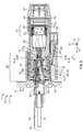
- Fig. 2 shows a section of the electric plug connection 1, wherein the section is in the x-z plane.
- the y axis points into the plane of the drawing.
- the loading lines which run to the electric plug connection 1 in the plugging direction S the stranded conductor 37 surrounding the loading lines and the mating short-circuiting contact 20 which is spaced from a central axis M counter to the z axis and the short-circuiting socket 65 which is associated with said mating short-circuiting contact are not shown.
- Fig. 2 clearly shows that the electric plug connector 5 overlaps with the electric mating plug connector 7 over almost the entire receptacle region 23.
- the contact securing device 39 secures the connection between the electric plug connector 5 and the electric mating plug connector 7.
- fig. 2 shows sealing elements 43 which run around in the z-y plane and which are arranged between the electric plug connector and the electric mating plug connector 7 or between the electric plug connector 5 and the stranded conductor (not shown in fig. 2 ).
- a retaining element 45 which retains both the sealing element 43 and the screening plates 47 in the plugging direction S to prevent them from dropping out of the electric plug connector 5.
- the retaining element 45 has a latching hook (not shown) which latches into a latching opening of the first plug housing 25 and therefore secures the retaining element 45 to prevent a relative movement in the plugging direction S away from the electric plug connector 5.
- the screening plates 47 extend from a retaining contour 49 of the retaining element 45 into a crimp region 51.
- the loading lines (not shown) which are enclosed by the stranded conductor 37 and guided through the strain-relief housing 27 in the plugging direction S are secured by means of the sleeves 53.
- the space element 55 serves to space apart the sleeves 53 from the first housing element.
- a contact housing 59 which has a plug face 99 pointing in the plugging direction S, is located partially in the cubature of the screening plates 47.
- the plug face 99 is shown in fig. 4 .
- the electric mating plug connector 7 comprises 2 socket receptacles 63.
- a short-circuiting socket 65 is shown which is electrically connected to the short-circuiting contact 19.
- Fig. 2 shows the electric plug connection in the plugging position 67.
- a short-circuiting bridge 69 projects into the socket receptacles 63 of the electric mating plug connector 7.
- the short-circuiting bridge 69 is located in a plugging position 70.
- the short-circuiting bridge 69 which is shown has a U-shaped profile, wherein the bottom 71 of the short-circuiting bridge 69 and parts of the limbs 73 of the short-circuiting bridge 69 are accommodated in a receptacle 75. Parts of the limbs 73 of the short-circuiting bridge 69 project into the socket receptacle 63 of the electric mating plug connector 7, where parts of the limbs 73 are respectively plugged into the corresponding short-circuiting socket 65.
- the limbs 73 of the short-circuiting bridge 69 enclose a securing element 77 which secures the short-circuiting bridge 69 against removal from the receptacle 75 of the contact housing 59.
- fig. 3 shows that the short-circuiting socket 65 has a crimp cable shoe 81 and spring contacts 83.
- the short-circuiting bridge 69 rests on the securing element 77 on the bearing point 74.
- the mating short-circuiting contact 20 is electrically and mechanically connected to the short-circuiting socket 65.
- the spring contacts 83 apply a holding force to the limbs 73 of the short-circuiting bridge 69, with the result that the short-circuiting bridge 69 is both held mechanically in the socket receptacle 63 of the electric mating plug connector 7 and connected in an electrically conductive fashion to the respective mating short-circuiting contact 20 by means of the short-circuiting socket 65.
- fig. 3 shows that the socket entries 85 have insertion slopes 87 which point counter to the plugging direction S and orient and guide the short-circuiting bridge.
- fig. 3 shows the geometry of the securing element 77, with more details being given on the geometry below.
- Fig. 4 shows the contact housing 59 in a perspective view.
- the contact housing 59 has a first loading socket 89a and a second loading socket 89b.
- the loading sockets 89a, 89b serve to accommodate the loading contacts 15 described above.
- the loading sockets 89a, 89b are inserted into corresponding socket receptacles 63 of the contact housing 59.
- the loading contacts 15 which are configured in a flat fashion to be able to be inserted into the corresponding loading socket 89a or 89b in one of two orientations perpendicular with respect to one another.
- one sidewall 91 is provided with a coding groove 93 into which an element (not shown), which protrudes in a correspondingly complementary fashion, of the first plug housing 25 can be inserted.
- the contact housing 59 has a coding bore 105 which, in conjunction with the coding groove 93, prevents faulty, faultily oriented plugging together of the electric connector to the electric mating plug connector 7.
- the loading sockets 89a, 89b are accommodated in loading bases 95 which have a square cross section with rounded corners.
- the loading bases 95 have guiding elevated portions 97 with which the loading bases 95, the contact housing 59 and therefore the entire electric plug connector 5 can be guided into the complementary receptacle 75 (not shown) of the electric mating plug connector.
- the faces of the loading bases 95 which point in the plugging direction S constitute the plug face 99.
- the receptacle 75 for the securing element 77 is arranged offset into the plug face 99, counter to the plugging direction S.
- the receptacle 75 comprises folds 101 pointing into the interior.
- Latching contours 103 of which one latching contour 103 is concealed by a loading base 95, are provided in the width direction b in the receptacle 75.
- the receptacle 75 has a width b A which is smaller than a height h A .
- the limbs 73 of the short-circuiting bridge 69 are arranged along the z axis and project from the receptacle 75 in the plugging direction, wherein the limbs 73 do not project beyond the loading bases 95 in the plugging direction S.
- the contact housing 59 is configured in and counter to the z direction with latching hooks 29 by means of which the contact housing 59 can be latched into complementary openings in the screening plates 47.
- the short-circuiting bridge 69 and the securing element 77 are shown in figs. 4 and 5 in a perspective view and a side view.
- the position of the short-circuiting bridge 69 and the securing element 77 with respect to one another corresponds to a possible position of these elements in the installed state of the electric plug connection 1, i.e. a possible deflection of the short-circuiting bridge 69 with respect to the securing element 77 in a plugging position 70 of the short-circuiting bridge 69.
- the U-shaped short-circuiting bridge 69 comprises the limbs 73 and the bottom 71 arranged along the z axis.
- the ends of the limbs 73 pointing in the plugging direction S have bevelled portions 107 which serve to interact with the corresponding insertion slopes 87 during the insertion of the short-circuiting bridge 69 into the short-circuiting sockets 65 in such a way that the short-circuiting bridge 69 is oriented as it slides along the insertion slopes 87 with the bevelled portions 107 in such a way that the limbs 73 of the short-circuiting bridge 69 can be accommodated correctly in the short-circuiting sockets 65.
- the end of the limbs 73 which projects in the plugging direction S has a width b K which is equal to or smaller than the width (not shown) of the complementary short-circuiting sockets 65 of the electric mating plug connector 7.
- the short-circuiting bridge 69 has tilting stops 109 in the embodiment shown in fig. 5 . These tilting stops 109 constitute a widening of the short-circuiting bridge 69 along the y axis and are configured in such a way that in the insert of the short-circuiting bridge 69 they can be employed in other components, for example in plug connectors, as press-in shoulders 111.
- the short-circuiting bridge 69 shown in fig. 5 has a tilting stop 109 in the bottom 71 of the short-circuiting bridge 69.
- the two further tilting stops 109 are located approximately in the centre of the length l K of the short-circuiting bridge 69 when viewed in the plugging direction S from the bottom 71.
- the short-circuiting bridge 69 shown in fig. 4 has fluting 113 which corresponds to a saw tooth pattern with 3 teeth in the embodiment of the short-circuiting bridge 69 which is shown.
- the fluting 113 can also be used to serve for attaching the short-circuiting bridge 69 in another component.
- the limbs 73 of the short-circuiting bridge 69 are parallel to one another, and the inner sides of the limbs 73 are spaced apart from one another at the distance h K .
- the short-circuiting bridge 69 shown in figures 5 and 6 is a punched-bent part, and the short-circuiting bridge 69 has its maximum width b K,max at the tilting stops 109.
- the securing element 77 has two sidewalls 115, an upper side 117 and an underside 119.
- the securing element 77 encloses, with its four walls 115, 117, 119, a cavity 121 which has an opening 123 in the plugging direction S and a bottom 71 counter to the plugging direction S.
- the upper side and the underside 117, 119 of the securing element 77 each have an inclined face 125, with the result that the height h S decreases counter to the plugging direction S, and the securing element 77 consequently tapers in its height h s counter to the plugging direction.
- the height of the securing element h s is less than the height of the short-circuiting bridge h K .
- the inclined faces 125 are inclined symmetrically in the positive and negative z directions with respect to the plugging direction S and have an angle of inclination 127 with respect to the plugging direction S.
- the edges of the securing element 77 which run in the x direction have folds 101 which point in the direction of the cavity 121. These folds 101 of the securing element 77 are each complementary to the corresponding fold 101 of the contact housing 59 ( fig. 4 ).
- the boundary of the opening 123 pointing in the plugging direction S comprises flange sections 129 which each comprise a stop face 131 pointing counter to the plugging direction S.
- Latching hooks 29 are provided on the sidewalls 115 of the securing element 77, wherein the stop faces 131, running perpendicularly with respect to the plugging direction S, of all the latching hooks 29 point in the plugging direction S.
- a latching hook 29a is located closer to the flange sections 129 of the corresponding sidewall 115 in the plugging direction S, wherein the latching hook 29a is located centrally between the two flange sections in the z direction.
- the stop faces 131, pointing counter to the plugging direction S, of the flange sections and the stop faces 131, pointing in the plugging direction S, of the latching hook 29a are spaced apart from one another by a length l R .
- the latching hooks 29b which are located closer to the bottom 71 of the securing element 77 have a maximum distance h R from one another.
- the securing element 77 is located completely between the limbs 73 of the short-circuiting bridge 69 in the plugging direction S, but the securing element 77 projects on both sides in the y direction over its entire length l S beyond the short-circuiting bridge.
- the contact housing 59 is illustrated in section along the line A-A (see fig. 1 ).
- the section lies in the y-z plane, and the plugging direction S points into the plane of the drawing.
- the sidewalls 91, the loading bases 95 and the latching hooks 29 can be seen.
- the securing element 77 is shown with a section A-A in a region in which the securing element 77 has already tapered, with the result that the inclined faces 125 can be seen in fig. 7 .
- the short-circuiting bridge 69 rests on the securing element 77 at the bearing point 74.
- the latching hooks 29b of the securing element 77 are accommodated in a guide groove 133 of the receptacle 75 in such a way that tilting of the securing element 77 about the y axis is prevented. Said guiding by the latching hooks 29b in the guide groove 133 takes place on both sides on the sidewalls 115 of the securing element 77.
- a room for manoeuvre 135 or play is formed between the securing element 77 secured in the receptacle 75 and the short-circuiting bridge 69.
- This play permits the short-circuiting bridge 69 to make a movement about its plugging position 70, and comprises movements in all three spatial directions and tilting about the three spatial axes.
- Fig. 8 shows the contact housing 59 in section along the line B-B (see fig. 2 ), wherein the section is in the y-z plane.
- the section shows a region in which the loading bases 95 merge monolithically with the bottom 71 of the contact housing and with the sidewalls 91.
- the coding bore 105, the latching hooks 29 and the retaining contours 49, on which loading sockets (not shown), inserted in the plugging direction into the socket receptacles 63, are supported, are also shown.
- Fig. 8 also shows the bottom 71 of the short-circuiting bridge 69, which bottom has a tilting stop 109.
- the inclined faces 125 of the securing element 77 have moved towards one another to such an extent that they are partially concealed, in particular in the z direction, by the tilting stop 109.
- the short-circuiting bridge 69 has room for manoeuvre along the z axis 135a, which room is therefore formed both in z direction and counter to the z direction.
- the short-circuiting bridge 69 also has room for manoeuvre in the y direction 135b, which room is also found along the y axis or counter to the y axis between the short-circuiting bridge 69 and the contact housing 59.
- the short-circuiting bridge 69 Depending on the relative position of the short-circuiting bridge 69 with respect to the contact housing 59 it is possible for the short-circuiting bridge 69 to be supported on the contact housing 59 in such a way that the room for manoeuvre 135 is not symmetrical about the tilting stop 109 of the short-circuiting bridge 69 but instead respectively extends only in or counter to a spatial direction.
- a bore 137 is shown in the bottom 71 of the short-circuiting bridge 69 in fig. 8 .
- this bore 137 can serve to accommodate a further tilting stop 109 which extends from the bottom of the receptacle 75 of the securing element 77 in the plugging direction S and can be configured in the form of a pin.
- the bore 137 of the short-circuiting bridge 69 may serve to attach the short-circuiting bridge in another configuration (not shown) of the electric plug connector by means of a suitable attachment means, for example a screw or a bolt.
- Fig. 9 shows the contact housing 59 in the section along the line C-C.
- the x-y plane corresponds to the plane of the drawing, and the z axis projects out of the plane of the drawing.
- the short-circuiting bridge 69 is arranged offset counter to the plugging direction S with respect to loading sockets (not shown) which are inserted in the socket receptacles 63.
- the stop faces 131 of the latching hooks 29a are supported on the latching contours 103 of the contact housing 59, and the latching hooks 29a, 29b of the securing element 77 are supported in and counter to the y direction in the receptacle 75 on the contact housing 59.
- the securing element 77 is therefore secured in the receptacle 75, as has already been described above.
- the concealed flange sections of the securing element 77 are supported on a retaining contour 49 which is also concealed in fig. 9 .
- Two of the four retaining contours 49 of the receptacle 75 are shown in fig. 4 .
- Fig. 9 also shows the coding groove 93 and the latching openings 31 for accommodating the latching hooks of the screening plates (both not shown).
Landscapes
- Details Of Connecting Devices For Male And Female Coupling (AREA)
- Connector Housings Or Holding Contact Members (AREA)
Claims (15)
- Connecteur électrique de branchement (5) destiné à être connecté à un connecteur de branchement homologue complémentaire (7) dans une direction de branchement (S), ayant un boîtier de branchement (25) qui a un réceptacle (75) dans lequel est logé un pont de court-circuitage (69), qui est maintenu fixement dans une position de branchement (70) et comporte deux contacts de court-circuitage (19) qui sont accessibles depuis l'extérieur du connecteur de branchement (5), à l'opposé de la direction de branchement (S), caractérisé en ce que le pont de court-circuitage (69) est logé avec un jeu, et pouvant être déplacé autour de la position de branchement (70), dans le réceptacle (75).
- Connecteur électrique de branchement (5) selon la revendication 1, caractérisé en ce que le pont de court-circuitage (69) est mobile transversalement par rapport à la direction de branchement (S).
- Connecteur électrique de branchement (5) selon la revendication 1 ou 2, caractérisé en ce que le pont de court-circuitage (69) est mobile dans la direction de branchement (S), ou la direction opposée à celle-ci.
- Connecteur électrique de branchement (5) selon l'une des revendications 1 à 3, caractérisé en ce que le pont de court-circuitage (69) est inclinable.
- Connecteur électrique de branchement (5) selon l'une des revendications 1 à 4, caractérisé en ce que le pont de court-circuitage (69) est logé dans un réceptacle en forme de U (75).
- Connecteur électrique de branchement (5) selon l'une des revendications 1 à 5, caractérisé en ce que le pont de court-circuitage (69) est en forme de U.
- Connecteur électrique de branchement (5) selon l'une des revendications 1 à 6, caractérisé en ce que le pont de court-circuitage (69) est fixé dans le réceptacle (75) par un élément de fixation (77) qui est branché dans le réceptacle (75).
- Connecteur électrique de branchement (5) selon la revendication 7, caractérisé en ce que l'élément de fixation (77) est situé entre les contacts de court-circuitage (19) du pont de court-circuitage (69).
- Connecteur électrique de branchement (5) selon la revendication 7 ou 8, caractérisé en ce que l'élément de fixation (77) a au moins un point d'appui (74) autour duquel le pont de court-circuitage (69) peut s'incliner.
- Connecteur électrique de branchement (5) selon les revendications 5 et 6, caractérisé en ce que le pont de court-circuitage en forme de U (69) est mobile transversalement par rapport à la direction de branchement (S) relativement au réceptacle en forme de U (75) et/ou dans la direction de branchement (S), ou la direction opposée à celle-ci, relativement à un fond (71) du réceptacle en forme de U (75).
- Connecteur électrique de branchement (5) selon l'une des revendications 7 à 10, caractérisé en ce que l'élément de fixation (77) peut être verrouillé dans le réceptacle (75).
- Connecteur électrique de branchement (5) selon l'une des revendications 7 à 11, caractérisé en ce que l'élément de fixation (77) se rétrécit à l'opposé de la direction de branchement (S) sur une étendue mesurée entre les contacts de court-circuitage (19) perpendiculairement par rapport à la direction de branchement (S).
- Connecteur électrique de branchement (5) selon l'une des revendications 4 à 12, caractérisé en ce que le pont de court-circuitage (69) peut s'incliner d'environ +/-2,5 °à environ +/- 15 ° par rapport à la direction de branchement (S).
- Connecteur électrique de branchement (5) selon l'une des revendications 4 à 13, caractérisé en ce que le pont de court-circuitage (69) a au moins une butée d'inclinaison (109).
- Connexion électrique de branchement (1) ayant un connecteur électrique de branchement (5) selon l'une des revendications 1 à 14 et un connecteur électrique de branchement homologue (7), caractérisée en ce que, dans une position de branchement (67), les contacts de court-circuitage (19) du pont de court-circuitage (69) sont connectés électriquement et d'une manière transmettant un mouvement à des contacts de court-circuitage homologues (20) du connecteur électrique de branchement homologue (7), mais sont découplés mécaniquement par un mouvement du connecteur électrique de branchement (5) du fait que le pont de court-circuitage (69) est logé dans le réceptacle (75) avec un jeu de telle sorte qu'il peut se déplacer autour de la position de branchement (70).
Applications Claiming Priority (2)
| Application Number | Priority Date | Filing Date | Title |
|---|---|---|---|
| DE102015214284.1A DE102015214284B4 (de) | 2015-07-28 | 2015-07-28 | Elektrischer Steckverbinder mit vibrationsresistenter Kurzschlussbrücke und elektrische Steckverbindung |
| PCT/EP2016/068023 WO2017017197A1 (fr) | 2015-07-28 | 2016-07-28 | Connecteur électrique enfichable à pont de court-circuitage résistant aux vibrations et connexion électrique enfichable |
Publications (2)
| Publication Number | Publication Date |
|---|---|
| EP3329559A1 EP3329559A1 (fr) | 2018-06-06 |
| EP3329559B1 true EP3329559B1 (fr) | 2019-05-15 |
Family
ID=56571311
Family Applications (1)
| Application Number | Title | Priority Date | Filing Date |
|---|---|---|---|
| EP16747761.1A Active EP3329559B1 (fr) | 2015-07-28 | 2016-07-28 | Connecteur électrique enfichable à pont de court-circuitage résistant aux vibrations et connexion électrique enfichable |
Country Status (7)
| Country | Link |
|---|---|
| US (1) | US10236633B2 (fr) |
| EP (1) | EP3329559B1 (fr) |
| JP (1) | JP6543407B2 (fr) |
| KR (1) | KR102041371B1 (fr) |
| CN (1) | CN107851935B (fr) |
| DE (1) | DE102015214284B4 (fr) |
| WO (1) | WO2017017197A1 (fr) |
Families Citing this family (8)
| Publication number | Priority date | Publication date | Assignee | Title |
|---|---|---|---|---|
| DE102019111691B4 (de) * | 2019-01-11 | 2020-10-15 | Hanon Systems | Anordnung zum Steckverbinden elektrischer Anschlüsse und Vorrichtung zum Antreiben eines Verdichters mit der Anordnung |
| JP7247629B2 (ja) * | 2019-02-13 | 2023-03-29 | 株式会社オートネットワーク技術研究所 | コネクタ装置 |
| DE102019130582A1 (de) * | 2019-11-13 | 2021-05-20 | Hanon Systems | Dichtanordnung einer Steckverbindung zum Steckverbinden elektrischer Anschlüsse und Vorrichtung zum Antreiben eines Verdichters mit der Dichtanordnung |
| DE102020108458A1 (de) * | 2020-03-27 | 2021-09-30 | Harting Electric Gmbh & Co. Kg | Hochleistungssteckverbindersystem |
| JP7219250B2 (ja) * | 2020-07-27 | 2023-02-07 | 矢崎総業株式会社 | コネクタ |
| JP7381541B2 (ja) * | 2021-10-19 | 2023-11-15 | 矢崎総業株式会社 | コネクタ |
| JP7321304B2 (ja) | 2022-01-05 | 2023-08-04 | ヤマハ発動機株式会社 | コネクタ |
| CN119283630A (zh) * | 2023-07-10 | 2025-01-10 | 开利公司 | 便携式交流-直流电源转换器和车载供电管理装置 |
Family Cites Families (26)
| Publication number | Priority date | Publication date | Assignee | Title |
|---|---|---|---|---|
| US4224486A (en) * | 1979-03-05 | 1980-09-23 | Amp Incorporated | Shunt protected power connector |
| JPH0412275U (fr) * | 1990-05-22 | 1992-01-31 | ||
| JP2725752B2 (ja) * | 1992-12-14 | 1998-03-11 | 矢崎総業株式会社 | コネクタ |
| US5464353A (en) * | 1993-04-21 | 1995-11-07 | Sumitomo Wiring Systems, Ltd. | Lock connector |
| DE4323839A1 (de) * | 1993-07-16 | 1995-01-19 | Kabelmetal Electro Gmbh | Vorrichtung zum Verbinden einer Sprengladung mit einer Stromquelle |
| JP3264297B2 (ja) * | 1993-09-30 | 2002-03-11 | 矢崎総業株式会社 | コネクタの結合検知装置 |
| JP2725759B2 (ja) * | 1993-11-18 | 1998-03-11 | 矢崎総業株式会社 | コネクタの結合検知装置及び短絡用接触子 |
| FR2725841B1 (fr) * | 1994-10-17 | 1997-01-03 | Cablage Cie Francaise | Connecteur electrique male |
| JP3264305B2 (ja) * | 1995-01-09 | 2002-03-11 | 矢崎総業株式会社 | 結合検知装置を備えたコネクタ |
| JP3596702B2 (ja) * | 1996-04-08 | 2004-12-02 | 矢崎総業株式会社 | コネクタ嵌合検知構造 |
| DE19702373B4 (de) * | 1997-01-23 | 2008-02-21 | The Whitaker Corp., Wilmington | Elektrischer Steckverbinder mit einer Kurzschlußfeder und Kurzschlußfeder |
| JP2001110511A (ja) * | 1999-10-07 | 2001-04-20 | Sumitomo Wiring Syst Ltd | 防水ジョイントキャップおよび、防水ジョイントコネクタ |
| JP4160573B2 (ja) * | 2005-04-05 | 2008-10-01 | モレックス インコーポレーテッド | 電子部品接続用コネクタ及び電子部品接続用端子 |
| DE102005041472A1 (de) * | 2005-09-01 | 2007-03-08 | Hirschmann Automotive Gmbh | Stecker oder Kuppler einer Steckverbindung für die Anwendung im Fahrzeugbereich mit einer Kurzschlussbrücke |
| JP4828311B2 (ja) * | 2006-06-02 | 2011-11-30 | タイコエレクトロニクスジャパン合同会社 | 電気コネクタ |
| SG143088A1 (en) * | 2006-11-22 | 2008-06-27 | Mea Technologies Pte Ltd | Electrical connector |
| US7601019B2 (en) * | 2007-06-22 | 2009-10-13 | Delphi Technologies, Inc. | Electrical connection system |
| DE102009052772B4 (de) * | 2008-12-01 | 2014-02-13 | Sumitomo Wiring Systems, Ltd. | Ein Verbinder |
| US7811115B1 (en) * | 2008-12-12 | 2010-10-12 | Tyco Electronics Corporation | Connector assembly with two stage latch |
| JP2010257917A (ja) | 2009-04-28 | 2010-11-11 | Sumitomo Wiring Syst Ltd | ショート端子 |
| JP5563241B2 (ja) * | 2009-05-15 | 2014-07-30 | スリーエム イノベイティブ プロパティズ カンパニー | 電気コネクタ |
| DE102009036411B3 (de) * | 2009-08-06 | 2011-02-03 | Tyco Electronics Amp Gmbh | Kombinierter elektrischer Steckverbinder mit Toleranzausgleich |
| JP5703139B2 (ja) * | 2011-06-20 | 2015-04-15 | モレックス インコーポレイテドMolex Incorporated | コネクタ |
| JP5707252B2 (ja) * | 2011-06-24 | 2015-04-22 | 矢崎総業株式会社 | コネクタ |
| EP2795740B1 (fr) * | 2011-12-22 | 2017-10-04 | Delphi International Operations Luxembourg S.à r.l. | Ensemble connecteur électrique amélioré |
| JP5783918B2 (ja) * | 2012-01-18 | 2015-09-24 | モレックス インコーポレイテドMolex Incorporated | コネクタ |
-
2015
- 2015-07-28 DE DE102015214284.1A patent/DE102015214284B4/de not_active Expired - Fee Related
-
2016
- 2016-07-28 WO PCT/EP2016/068023 patent/WO2017017197A1/fr not_active Ceased
- 2016-07-28 JP JP2018503633A patent/JP6543407B2/ja active Active
- 2016-07-28 EP EP16747761.1A patent/EP3329559B1/fr active Active
- 2016-07-28 CN CN201680044506.XA patent/CN107851935B/zh active Active
- 2016-07-28 KR KR1020187005817A patent/KR102041371B1/ko active Active
-
2018
- 2018-01-25 US US15/879,774 patent/US10236633B2/en active Active
Non-Patent Citations (1)
| Title |
|---|
| None * |
Also Published As
| Publication number | Publication date |
|---|---|
| JP2018521485A (ja) | 2018-08-02 |
| JP6543407B2 (ja) | 2019-07-10 |
| US10236633B2 (en) | 2019-03-19 |
| KR20180034610A (ko) | 2018-04-04 |
| CN107851935A (zh) | 2018-03-27 |
| KR102041371B1 (ko) | 2019-11-06 |
| DE102015214284A1 (de) | 2017-02-02 |
| US20180151984A1 (en) | 2018-05-31 |
| EP3329559A1 (fr) | 2018-06-06 |
| DE102015214284B4 (de) | 2017-03-30 |
| CN107851935B (zh) | 2020-09-29 |
| WO2017017197A1 (fr) | 2017-02-02 |
Similar Documents
| Publication | Publication Date | Title |
|---|---|---|
| EP3329559A1 (fr) | Connecteur électrique enfichable à pont de court-circuitage résistant aux vibrations et connexion électrique enfichable | |
| JP5876510B2 (ja) | 電気コネクタ及びコネクタシステム | |
| CN105493352B (zh) | 高电压手指保护 | |
| US10283904B2 (en) | Connector | |
| US6382992B1 (en) | Electrical connector assembly with improved camming system | |
| US8287297B2 (en) | Clearance compensation unit | |
| EP3116071A1 (fr) | Ensemble connecteur | |
| US20150311633A1 (en) | Plug connector | |
| MX2012010379A (es) | Conector electrico, conector de empalme electrico, conexion de enchufe electrico asi como un cable electrico ensamblado. | |
| CN110277278B (zh) | 插座 | |
| EP3540873B1 (fr) | Connecteur et douille | |
| EP3648259B1 (fr) | Connecteur électrique avec verrous et projections d'assurance de position de terminal fourni sur un couvercle articulé | |
| JP5808504B2 (ja) | 電気的なカップリングエレメント | |
| WO2019243935A1 (fr) | Connecteur électrique avec dispositif de vérification de position de borne | |
| US20180183171A1 (en) | Joint connector | |
| JP2018206766A (ja) | コンタクトハウジング、コンタクトハウジングレセプタクル、および電気コネクタ | |
| JP2013257960A (ja) | コネクタ | |
| US9231338B2 (en) | Variable wire strain relief connector | |
| JPS64791B2 (fr) | ||
| JP2024534115A (ja) | ヘッダパワーコネクタ | |
| US6287153B1 (en) | Cable connector with improved engagement mechanism | |
| KR102703587B1 (ko) | 커넥터 포지션 보장 요소를 포함하는 전기 커넥터 | |
| CN113196578B (zh) | 用于沿数个空间方向进行接触的插式连接器部件 | |
| KR102707016B1 (ko) | 정렬기능을 갖는 커넥터 및 이를 포함하는 커넥터어셈블리 | |
| CN116918192A (zh) | 高压插塞连接器装置 |
Legal Events
| Date | Code | Title | Description |
|---|---|---|---|
| STAA | Information on the status of an ep patent application or granted ep patent |
Free format text: STATUS: THE INTERNATIONAL PUBLICATION HAS BEEN MADE |
|
| PUAI | Public reference made under article 153(3) epc to a published international application that has entered the european phase |
Free format text: ORIGINAL CODE: 0009012 |
|
| STAA | Information on the status of an ep patent application or granted ep patent |
Free format text: STATUS: REQUEST FOR EXAMINATION WAS MADE |
|
| 17P | Request for examination filed |
Effective date: 20180221 |
|
| AK | Designated contracting states |
Kind code of ref document: A1 Designated state(s): AL AT BE BG CH CY CZ DE DK EE ES FI FR GB GR HR HU IE IS IT LI LT LU LV MC MK MT NL NO PL PT RO RS SE SI SK SM TR |
|
| AX | Request for extension of the european patent |
Extension state: BA ME |
|
| DAV | Request for validation of the european patent (deleted) | ||
| DAX | Request for extension of the european patent (deleted) | ||
| GRAP | Despatch of communication of intention to grant a patent |
Free format text: ORIGINAL CODE: EPIDOSNIGR1 |
|
| STAA | Information on the status of an ep patent application or granted ep patent |
Free format text: STATUS: GRANT OF PATENT IS INTENDED |
|
| INTG | Intention to grant announced |
Effective date: 20190114 |
|
| GRAS | Grant fee paid |
Free format text: ORIGINAL CODE: EPIDOSNIGR3 |
|
| GRAA | (expected) grant |
Free format text: ORIGINAL CODE: 0009210 |
|
| STAA | Information on the status of an ep patent application or granted ep patent |
Free format text: STATUS: THE PATENT HAS BEEN GRANTED |
|
| AK | Designated contracting states |
Kind code of ref document: B1 Designated state(s): AL AT BE BG CH CY CZ DE DK EE ES FI FR GB GR HR HU IE IS IT LI LT LU LV MC MK MT NL NO PL PT RO RS SE SI SK SM TR |
|
| REG | Reference to a national code |
Ref country code: CH Ref legal event code: EP |
|
| REG | Reference to a national code |
Ref country code: DE Ref legal event code: R096 Ref document number: 602016014070 Country of ref document: DE |
|
| REG | Reference to a national code |
Ref country code: IE Ref legal event code: FG4D |
|
| REG | Reference to a national code |
Ref country code: NL Ref legal event code: MP Effective date: 20190515 |
|
| REG | Reference to a national code |
Ref country code: LT Ref legal event code: MG4D |
|
| PG25 | Lapsed in a contracting state [announced via postgrant information from national office to epo] |
Ref country code: LT Free format text: LAPSE BECAUSE OF FAILURE TO SUBMIT A TRANSLATION OF THE DESCRIPTION OR TO PAY THE FEE WITHIN THE PRESCRIBED TIME-LIMIT Effective date: 20190515 Ref country code: HR Free format text: LAPSE BECAUSE OF FAILURE TO SUBMIT A TRANSLATION OF THE DESCRIPTION OR TO PAY THE FEE WITHIN THE PRESCRIBED TIME-LIMIT Effective date: 20190515 Ref country code: NL Free format text: LAPSE BECAUSE OF FAILURE TO SUBMIT A TRANSLATION OF THE DESCRIPTION OR TO PAY THE FEE WITHIN THE PRESCRIBED TIME-LIMIT Effective date: 20190515 Ref country code: SE Free format text: LAPSE BECAUSE OF FAILURE TO SUBMIT A TRANSLATION OF THE DESCRIPTION OR TO PAY THE FEE WITHIN THE PRESCRIBED TIME-LIMIT Effective date: 20190515 Ref country code: NO Free format text: LAPSE BECAUSE OF FAILURE TO SUBMIT A TRANSLATION OF THE DESCRIPTION OR TO PAY THE FEE WITHIN THE PRESCRIBED TIME-LIMIT Effective date: 20190815 Ref country code: FI Free format text: LAPSE BECAUSE OF FAILURE TO SUBMIT A TRANSLATION OF THE DESCRIPTION OR TO PAY THE FEE WITHIN THE PRESCRIBED TIME-LIMIT Effective date: 20190515 Ref country code: AL Free format text: LAPSE BECAUSE OF FAILURE TO SUBMIT A TRANSLATION OF THE DESCRIPTION OR TO PAY THE FEE WITHIN THE PRESCRIBED TIME-LIMIT Effective date: 20190515 Ref country code: PT Free format text: LAPSE BECAUSE OF FAILURE TO SUBMIT A TRANSLATION OF THE DESCRIPTION OR TO PAY THE FEE WITHIN THE PRESCRIBED TIME-LIMIT Effective date: 20190915 Ref country code: ES Free format text: LAPSE BECAUSE OF FAILURE TO SUBMIT A TRANSLATION OF THE DESCRIPTION OR TO PAY THE FEE WITHIN THE PRESCRIBED TIME-LIMIT Effective date: 20190515 |
|
| PG25 | Lapsed in a contracting state [announced via postgrant information from national office to epo] |
Ref country code: BG Free format text: LAPSE BECAUSE OF FAILURE TO SUBMIT A TRANSLATION OF THE DESCRIPTION OR TO PAY THE FEE WITHIN THE PRESCRIBED TIME-LIMIT Effective date: 20190815 Ref country code: LV Free format text: LAPSE BECAUSE OF FAILURE TO SUBMIT A TRANSLATION OF THE DESCRIPTION OR TO PAY THE FEE WITHIN THE PRESCRIBED TIME-LIMIT Effective date: 20190515 Ref country code: RS Free format text: LAPSE BECAUSE OF FAILURE TO SUBMIT A TRANSLATION OF THE DESCRIPTION OR TO PAY THE FEE WITHIN THE PRESCRIBED TIME-LIMIT Effective date: 20190515 Ref country code: GR Free format text: LAPSE BECAUSE OF FAILURE TO SUBMIT A TRANSLATION OF THE DESCRIPTION OR TO PAY THE FEE WITHIN THE PRESCRIBED TIME-LIMIT Effective date: 20190816 |
|
| REG | Reference to a national code |
Ref country code: AT Ref legal event code: MK05 Ref document number: 1134526 Country of ref document: AT Kind code of ref document: T Effective date: 20190515 |
|
| PG25 | Lapsed in a contracting state [announced via postgrant information from national office to epo] |
Ref country code: DK Free format text: LAPSE BECAUSE OF FAILURE TO SUBMIT A TRANSLATION OF THE DESCRIPTION OR TO PAY THE FEE WITHIN THE PRESCRIBED TIME-LIMIT Effective date: 20190515 Ref country code: AT Free format text: LAPSE BECAUSE OF FAILURE TO SUBMIT A TRANSLATION OF THE DESCRIPTION OR TO PAY THE FEE WITHIN THE PRESCRIBED TIME-LIMIT Effective date: 20190515 Ref country code: CZ Free format text: LAPSE BECAUSE OF FAILURE TO SUBMIT A TRANSLATION OF THE DESCRIPTION OR TO PAY THE FEE WITHIN THE PRESCRIBED TIME-LIMIT Effective date: 20190515 Ref country code: EE Free format text: LAPSE BECAUSE OF FAILURE TO SUBMIT A TRANSLATION OF THE DESCRIPTION OR TO PAY THE FEE WITHIN THE PRESCRIBED TIME-LIMIT Effective date: 20190515 Ref country code: SK Free format text: LAPSE BECAUSE OF FAILURE TO SUBMIT A TRANSLATION OF THE DESCRIPTION OR TO PAY THE FEE WITHIN THE PRESCRIBED TIME-LIMIT Effective date: 20190515 |
|
| REG | Reference to a national code |
Ref country code: DE Ref legal event code: R097 Ref document number: 602016014070 Country of ref document: DE |
|
| PG25 | Lapsed in a contracting state [announced via postgrant information from national office to epo] |
Ref country code: SM Free format text: LAPSE BECAUSE OF FAILURE TO SUBMIT A TRANSLATION OF THE DESCRIPTION OR TO PAY THE FEE WITHIN THE PRESCRIBED TIME-LIMIT Effective date: 20190515 Ref country code: MC Free format text: LAPSE BECAUSE OF FAILURE TO SUBMIT A TRANSLATION OF THE DESCRIPTION OR TO PAY THE FEE WITHIN THE PRESCRIBED TIME-LIMIT Effective date: 20190515 |
|
| REG | Reference to a national code |
Ref country code: CH Ref legal event code: PL |
|
| PLBE | No opposition filed within time limit |
Free format text: ORIGINAL CODE: 0009261 |
|
| STAA | Information on the status of an ep patent application or granted ep patent |
Free format text: STATUS: NO OPPOSITION FILED WITHIN TIME LIMIT |
|
| PG25 | Lapsed in a contracting state [announced via postgrant information from national office to epo] |
Ref country code: TR Free format text: LAPSE BECAUSE OF FAILURE TO SUBMIT A TRANSLATION OF THE DESCRIPTION OR TO PAY THE FEE WITHIN THE PRESCRIBED TIME-LIMIT Effective date: 20190515 |
|
| REG | Reference to a national code |
Ref country code: BE Ref legal event code: MM Effective date: 20190731 |
|
| 26N | No opposition filed |
Effective date: 20200218 |
|
| PG25 | Lapsed in a contracting state [announced via postgrant information from national office to epo] |
Ref country code: PL Free format text: LAPSE BECAUSE OF FAILURE TO SUBMIT A TRANSLATION OF THE DESCRIPTION OR TO PAY THE FEE WITHIN THE PRESCRIBED TIME-LIMIT Effective date: 20190515 |
|
| PG25 | Lapsed in a contracting state [announced via postgrant information from national office to epo] |
Ref country code: LU Free format text: LAPSE BECAUSE OF NON-PAYMENT OF DUE FEES Effective date: 20190728 Ref country code: LI Free format text: LAPSE BECAUSE OF NON-PAYMENT OF DUE FEES Effective date: 20190731 Ref country code: SI Free format text: LAPSE BECAUSE OF FAILURE TO SUBMIT A TRANSLATION OF THE DESCRIPTION OR TO PAY THE FEE WITHIN THE PRESCRIBED TIME-LIMIT Effective date: 20190515 Ref country code: CH Free format text: LAPSE BECAUSE OF NON-PAYMENT OF DUE FEES Effective date: 20190731 Ref country code: BE Free format text: LAPSE BECAUSE OF NON-PAYMENT OF DUE FEES Effective date: 20190731 |
|
| PG25 | Lapsed in a contracting state [announced via postgrant information from national office to epo] |
Ref country code: IE Free format text: LAPSE BECAUSE OF NON-PAYMENT OF DUE FEES Effective date: 20190728 |
|
| GBPC | Gb: european patent ceased through non-payment of renewal fee |
Effective date: 20200728 |
|
| PG25 | Lapsed in a contracting state [announced via postgrant information from national office to epo] |
Ref country code: RO Free format text: LAPSE BECAUSE OF FAILURE TO SUBMIT A TRANSLATION OF THE DESCRIPTION OR TO PAY THE FEE WITHIN THE PRESCRIBED TIME-LIMIT Effective date: 20190515 Ref country code: GB Free format text: LAPSE BECAUSE OF NON-PAYMENT OF DUE FEES Effective date: 20200728 |
|
| PG25 | Lapsed in a contracting state [announced via postgrant information from national office to epo] |
Ref country code: CY Free format text: LAPSE BECAUSE OF FAILURE TO SUBMIT A TRANSLATION OF THE DESCRIPTION OR TO PAY THE FEE WITHIN THE PRESCRIBED TIME-LIMIT Effective date: 20190515 |
|
| PG25 | Lapsed in a contracting state [announced via postgrant information from national office to epo] |
Ref country code: IS Free format text: LAPSE BECAUSE OF FAILURE TO SUBMIT A TRANSLATION OF THE DESCRIPTION OR TO PAY THE FEE WITHIN THE PRESCRIBED TIME-LIMIT Effective date: 20190915 |
|
| PG25 | Lapsed in a contracting state [announced via postgrant information from national office to epo] |
Ref country code: MT Free format text: LAPSE BECAUSE OF FAILURE TO SUBMIT A TRANSLATION OF THE DESCRIPTION OR TO PAY THE FEE WITHIN THE PRESCRIBED TIME-LIMIT Effective date: 20190515 Ref country code: HU Free format text: LAPSE BECAUSE OF FAILURE TO SUBMIT A TRANSLATION OF THE DESCRIPTION OR TO PAY THE FEE WITHIN THE PRESCRIBED TIME-LIMIT; INVALID AB INITIO Effective date: 20160728 |
|
| PG25 | Lapsed in a contracting state [announced via postgrant information from national office to epo] |
Ref country code: MK Free format text: LAPSE BECAUSE OF FAILURE TO SUBMIT A TRANSLATION OF THE DESCRIPTION OR TO PAY THE FEE WITHIN THE PRESCRIBED TIME-LIMIT Effective date: 20190515 |
|
| PGFP | Annual fee paid to national office [announced via postgrant information from national office to epo] |
Ref country code: FR Payment date: 20250610 Year of fee payment: 10 |
|
| PGFP | Annual fee paid to national office [announced via postgrant information from national office to epo] |
Ref country code: DE Payment date: 20250604 Year of fee payment: 10 |
|
| PGFP | Annual fee paid to national office [announced via postgrant information from national office to epo] |
Ref country code: IT Payment date: 20250623 Year of fee payment: 10 |