EP3329580B1 - Dispositif de freinage pour moteur électrique d'entraînement - Google Patents
Dispositif de freinage pour moteur électrique d'entraînement Download PDFInfo
- Publication number
- EP3329580B1 EP3329580B1 EP15820859.5A EP15820859A EP3329580B1 EP 3329580 B1 EP3329580 B1 EP 3329580B1 EP 15820859 A EP15820859 A EP 15820859A EP 3329580 B1 EP3329580 B1 EP 3329580B1
- Authority
- EP
- European Patent Office
- Prior art keywords
- braking device
- braking
- base body
- incisions
- drive motor
- Prior art date
- Legal status (The legal status is an assumption and is not a legal conclusion. Google has not performed a legal analysis and makes no representation as to the accuracy of the status listed.)
- Active
Links
Images









Classifications
-
- H—ELECTRICITY
- H02—GENERATION; CONVERSION OR DISTRIBUTION OF ELECTRIC POWER
- H02K—DYNAMO-ELECTRIC MACHINES
- H02K7/00—Arrangements for handling mechanical energy structurally associated with dynamo-electric machines, e.g. structural association with mechanical driving motors or auxiliary dynamo-electric machines
- H02K7/10—Structural association with clutches, brakes, gears, pulleys or mechanical starters
- H02K7/102—Structural association with clutches, brakes, gears, pulleys or mechanical starters with friction brakes
-
- F—MECHANICAL ENGINEERING; LIGHTING; HEATING; WEAPONS; BLASTING
- F16—ENGINEERING ELEMENTS AND UNITS; GENERAL MEASURES FOR PRODUCING AND MAINTAINING EFFECTIVE FUNCTIONING OF MACHINES OR INSTALLATIONS; THERMAL INSULATION IN GENERAL
- F16D—COUPLINGS FOR TRANSMITTING ROTATION; CLUTCHES; BRAKES
- F16D59/00—Self-acting brakes, e.g. coming into operation at a predetermined speed
-
- F—MECHANICAL ENGINEERING; LIGHTING; HEATING; WEAPONS; BLASTING
- F16—ENGINEERING ELEMENTS AND UNITS; GENERAL MEASURES FOR PRODUCING AND MAINTAINING EFFECTIVE FUNCTIONING OF MACHINES OR INSTALLATIONS; THERMAL INSULATION IN GENERAL
- F16D—COUPLINGS FOR TRANSMITTING ROTATION; CLUTCHES; BRAKES
- F16D65/00—Parts or details
- F16D65/02—Braking members; Mounting thereof
- F16D65/04—Bands, shoes or pads; Pivots or supporting members therefor
- F16D65/06—Bands, shoes or pads; Pivots or supporting members therefor for externally-engaging brakes
-
- F—MECHANICAL ENGINEERING; LIGHTING; HEATING; WEAPONS; BLASTING
- F16—ENGINEERING ELEMENTS AND UNITS; GENERAL MEASURES FOR PRODUCING AND MAINTAINING EFFECTIVE FUNCTIONING OF MACHINES OR INSTALLATIONS; THERMAL INSULATION IN GENERAL
- F16D—COUPLINGS FOR TRANSMITTING ROTATION; CLUTCHES; BRAKES
- F16D65/00—Parts or details
- F16D65/14—Actuating mechanisms for brakes; Means for initiating operation at a predetermined position
- F16D65/16—Actuating mechanisms for brakes; Means for initiating operation at a predetermined position arranged in or on the brake
- F16D65/18—Actuating mechanisms for brakes; Means for initiating operation at a predetermined position arranged in or on the brake adapted for drawing members together, e.g. for disc brakes
-
- H—ELECTRICITY
- H02—GENERATION; CONVERSION OR DISTRIBUTION OF ELECTRIC POWER
- H02K—DYNAMO-ELECTRIC MACHINES
- H02K7/00—Arrangements for handling mechanical energy structurally associated with dynamo-electric machines, e.g. structural association with mechanical driving motors or auxiliary dynamo-electric machines
- H02K7/08—Structural association with bearings
-
- H—ELECTRICITY
- H02—GENERATION; CONVERSION OR DISTRIBUTION OF ELECTRIC POWER
- H02K—DYNAMO-ELECTRIC MACHINES
- H02K7/00—Arrangements for handling mechanical energy structurally associated with dynamo-electric machines, e.g. structural association with mechanical driving motors or auxiliary dynamo-electric machines
- H02K7/10—Structural association with clutches, brakes, gears, pulleys or mechanical starters
-
- H—ELECTRICITY
- H02—GENERATION; CONVERSION OR DISTRIBUTION OF ELECTRIC POWER
- H02K—DYNAMO-ELECTRIC MACHINES
- H02K7/00—Arrangements for handling mechanical energy structurally associated with dynamo-electric machines, e.g. structural association with mechanical driving motors or auxiliary dynamo-electric machines
- H02K7/10—Structural association with clutches, brakes, gears, pulleys or mechanical starters
- H02K7/116—Structural association with clutches, brakes, gears, pulleys or mechanical starters with gears
- H02K7/1163—Structural association with clutches, brakes, gears, pulleys or mechanical starters with gears where at least two gears have non-parallel axes without having orbital motion
- H02K7/1166—Structural association with clutches, brakes, gears, pulleys or mechanical starters with gears where at least two gears have non-parallel axes without having orbital motion comprising worm and worm-wheel
-
- F—MECHANICAL ENGINEERING; LIGHTING; HEATING; WEAPONS; BLASTING
- F16—ENGINEERING ELEMENTS AND UNITS; GENERAL MEASURES FOR PRODUCING AND MAINTAINING EFFECTIVE FUNCTIONING OF MACHINES OR INSTALLATIONS; THERMAL INSULATION IN GENERAL
- F16D—COUPLINGS FOR TRANSMITTING ROTATION; CLUTCHES; BRAKES
- F16D2121/00—Type of actuator operation force
- F16D2121/14—Mechanical
-
- F—MECHANICAL ENGINEERING; LIGHTING; HEATING; WEAPONS; BLASTING
- F16—ENGINEERING ELEMENTS AND UNITS; GENERAL MEASURES FOR PRODUCING AND MAINTAINING EFFECTIVE FUNCTIONING OF MACHINES OR INSTALLATIONS; THERMAL INSULATION IN GENERAL
- F16D—COUPLINGS FOR TRANSMITTING ROTATION; CLUTCHES; BRAKES
- F16D2200/00—Materials; Production methods therefor
- F16D2200/0004—Materials; Production methods therefor metallic
-
- F—MECHANICAL ENGINEERING; LIGHTING; HEATING; WEAPONS; BLASTING
- F16—ENGINEERING ELEMENTS AND UNITS; GENERAL MEASURES FOR PRODUCING AND MAINTAINING EFFECTIVE FUNCTIONING OF MACHINES OR INSTALLATIONS; THERMAL INSULATION IN GENERAL
- F16D—COUPLINGS FOR TRANSMITTING ROTATION; CLUTCHES; BRAKES
- F16D2200/00—Materials; Production methods therefor
- F16D2200/0004—Materials; Production methods therefor metallic
- F16D2200/0008—Ferro
- F16D2200/0021—Steel
-
- F—MECHANICAL ENGINEERING; LIGHTING; HEATING; WEAPONS; BLASTING
- F16—ENGINEERING ELEMENTS AND UNITS; GENERAL MEASURES FOR PRODUCING AND MAINTAINING EFFECTIVE FUNCTIONING OF MACHINES OR INSTALLATIONS; THERMAL INSULATION IN GENERAL
- F16D—COUPLINGS FOR TRANSMITTING ROTATION; CLUTCHES; BRAKES
- F16D2200/00—Materials; Production methods therefor
- F16D2200/0034—Materials; Production methods therefor non-metallic
Definitions
- the invention relates to a braking device for an electric drive motor, in particular a drive motor with an armature shaft projecting over the motor housing, which has at least one braking element and an energy accumulator, the energy accumulator permanently applying a braking force to the braking element.
- Such drive motors are used in a variety of ways, including in electrical furniture drives that are used to adjust a furniture part.
- the furniture part can be, for example, a head or foot part of a bed or seating.
- the driving force of the drive motor is often transmitted to the furniture part via a worm gear with a downstream spindle drive.
- the worm gear is formed by a worm attached or formed on the armature shaft of the drive motor in connection with a worm wheel in which the worm engages.
- the worm gear has the advantage of self-locking, which prevents a piece of furniture loaded with weight from being lowered when the motor is switched off.
- Such braking devices can be designed as actively controllable brakes, which, for example, brake the armature shaft of the motor in an electromechanically actuated manner at a standstill.
- brakes that are not actively controlled can also be used for an armature shaft of an electric drive motor.
- Such brakes are from the publications DE 20 2004 008 713 U1 and DE 20 2004 008 714 U1 known.
- With these braking devices there is a slight permanent braking of the armature shaft, which is overcome by the torque during operation of the drive motor, but which is nevertheless sufficiently large to be at a standstill in connection with the self-locking by the worm gear to prevent unintentional rotation of the electric drive motor by loading the adjustable furniture part.
- the braking devices presented in the cited documents and mentioned at the beginning each have a force storage device, for example a spring, which permanently apply a braking force to a braking element.
- the braking element e.g. pressed against a brake rotor, which is rotatably connected to the armature shaft of the motor.
- the publication CN 203827112 U also shows a permanently braked electric motor, designed as a tubular motor for use in shading systems, for example.
- the motor has three brake elements arranged axially one behind the other in the motor.
- the document DE 20 2004 008 713 U1 discloses a braking device for an electric drive motor, which has a braking element and an energy accumulator, the energy accumulator permanently applying a braking force to a friction surface of the braking element.
- the permanent braking devices mentioned have proven their worth and are simpler in construction compared to actively controlled braking devices and are therefore generally less expensive. However, they are not inexpensive to manufacture, since it must be ensured that the energy accumulator and brake elements, which are made of different materials, are securely connected to one another without this increasing the production outlay.
- a braking device of the type mentioned at the outset is characterized in that the energy accumulator and the braking element are constructed in one piece from the same material.
- the invention is based on the basic idea that, with an appropriate shape, the braking element itself can achieve a sufficient spring effect in order to apply the required braking force.
- the braking device is ring-shaped, a self-contained ring-shaped base body having a central opening for receiving a section of the armature shaft of the drive motor. Radially and / or obliquely running incisions which are open inward and / or outward are preferably made in the base body. Because the base body is self-contained all the way around, it can be made of exert a radially acting braking force on the armature shaft guided through the central opening without any support on external components.
- the material thickness of the annular base body is reduced by the incisions, so that it can be expanded more easily, whereby a spring effect is achieved.
- the number and depth of the incisions makes it possible to set the desired spring force and also the spring travel for the material used for the base body.
- a relatively hard and not particularly elastic material can be used for the base body, which accordingly wears little in spite of the braking action applied, and nevertheless results in a spring action with sufficient spring travel and a spring force that is required and in particular not too strong.
- Several incisions can preferably be arranged in a star shape. Incisions that are open inwards and outwards can alternate all around.
- zinc or bronze or a plastic that is as temperature-resistant as possible for example PEEK (polyether ether ketone)
- PEEK polyether ether ketone
- the materials mentioned are generally softer than the commonly used material of the armature shaft, namely solid, unhardened steel, so that braking the armature shaft does not damage the surface of the armature shaft. Nevertheless, the materials mentioned are hard enough to achieve a braking effect that is as wear-free as possible and thus for a long life cycle.
- the aforementioned braking device can rest against the motor housing in a simple and space-saving manner when plugged onto the armature shaft, or can be inserted into a receptacle in the motor housing.
- the braking device it is only necessary to prevent the motor shaft from slipping axially, which can be achieved by holding or locking projections.
- the braking device is to be secured against rotation, which can also be done, for example, by means of locking or holding projections which are arranged on the motor housing. These projections can engage, for example, in the above-mentioned incisions in the base body of the braking device.
- projections can be arranged on the outer circumference of the base body, which cooperate with the holding or locking projections mentioned and fix the braking device non-rotatably on the motor housing.
- the holding or locking projections can be arranged or formed on the motor housing itself or on a motor holder.
- a surface of the at least one braking element itself forms the friction surface particularly advantageously.
- the braking element is made of plastic in an injection molding process.
- a surface of the ring segment forms the friction surface.
- a friction surface that is particularly suitable for braking can be provided regardless of the material of the base body.
- the braking device is formed integrally with a motor holding plate. This further reduces the manufacturing and assembly costs for the electric motor drive.
- the braking device can also be integrated into the electric drive motor with the same advantage and, in particular, additionally take on the function of a slide bearing for the drive shaft.
- the rear axle bearing of a drive motor is often not designed as a ball bearing but as a plain bearing.
- the plain bearing provided as standard can be replaced by the braking device according to the invention with a plain bearing function.
- the braking device is formed in a ring from a sheet material, preferably in an embossing process.
- the braking device has an annular base body with a central inner opening for receiving the axle shaft.
- the base body has incisions which are open toward the central opening and through which spring tongues are formed.
- the spring tongues are bent out of the plane of the annular base body towards the inner opening, so that they have an axially extending section in their front end, with which the spring tongues press radially onto an axle shaft guided through the central opening and thus exert braking force.
- the braking element can be fixed to the motor housing in a simple and space-saving manner.
- the braking device is also made in one piece, preferably from a thin and resilient sheet material. The spring force is achieved by the shape of the spring tongues exhibited and running axially in their respective end sections.
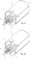
- FIGS. 1a to 1c each show in the same way an electric drive motor 1 with a braking device 10 in an isometric view.
- Figure 1d shows the drive motor 1 without a braking device in the same representation.
- the drive motor 1 each has a housing 2 with a flange plate 3, on which there are fastening options for the drive motor 1.
- a bearing 4 is also centrally located in the flange plate 3 (cf. Figure 1d ) arranged for an axle shaft 5 of the drive motor 1.
- the bearing 4 can be held in a bearing seat of the flange plate 3 either accessible from the outside or inserted from the inside of the housing 2.
- a comparable bearing for the axle shaft 5 is arranged on the opposite side of the housing 2.
- the bearing 4 provided in the flange plate 3 is, for example, a roller bearing, e.g. B. a ball bearing or a roller bearing.
- the bearing arranged on the opposite side can also be provided with a rolling element bearing of this type or a plain bearing.
- the axle shaft 5 protrudes from the flange plate 3. In addition to an optional bearing journal at the end of the axle shaft 5, this is provided with a worm 6.
- the worm 6 can be a separate part placed on the axle shaft 5, or it can be formed integrally with the axle shaft 5.
- the axle shaft 5 initially projects with an axle section 7 beyond the flange plate 3 before the worm 6 connects to it.
- the Axle section 7 is cylindrical with a smooth surface, the diameter of the axle section 7 at least slightly exceeding the outer diameter of the screw 6.
- the braking device 10 is in each case annular and is pushed onto the axle shaft 5 to such an extent that it lies essentially against the flange plate 3 and acts on the axle section 7 of the axle shaft 5.
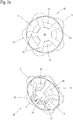
- the three embodiments of the braking device 10 according to the Figures 1a to 1c are in the Figures 2a to 2c each shown in more detail.
- the Figures 2a to 2c each show in their upper part a top view of the braking device 10 and in the lower part an isometric oblique view of the braking device 10.
- the braking device 10 is made in one piece from an annular base body 11, in particular in a stamping and bending or embossing process from a sheet metal element.
- the material of the base body 11 is preferably a spring plate, for example a steel plate or a plate made of spring bronze.
- the annular base body 11 is closed all around in the outer region, so that it can exert radial forces on the axle shaft 5. This is guided through a central opening 14 in the base body 11, which forms an axis receptacle.
- the base body 11 On the outer circumference, the base body 11 has radially protruding sections 13 which alternate with sections of smaller diameter. With the help of the radially projecting sections 13, the braking device 10 can be held in a rotationally fixed manner relative to the drive motor 1.
- holding or latching projections can be formed on the flange plate 3 of the drive motor 1, which hold the braking device 10 on the one hand in a rotationally fixed manner and on the other hand fix it to the flange plate 3 in the axial direction.
- the flange plate 3 has no such holding or locking projections.
- the brake device 10 is fixed via a motor mount (not shown here) to which the drive motor 1 is also attached.
- incisions 15 are made in a star shape, which are open inwards to the central opening 14. These cuts are also called inner cuts 15 below.
- inner Incisions 15 are formed from the base body 11 in the area of the central opening 14, spring tongues 16 which are bent out of the plane of the base body 11 in the stamping process in such a way that they are in a front free section in the axial direction of the axle shaft 5, that is to say essentially perpendicular to the plane , in which the outer circumferential section of the base body 11 lies, are aligned.
- These front sections of the spring tongues 16 press on the axle section 7 of the axle shaft 5 and thus brake the axle shaft 5. These sections form braking elements 17 of the braking device.
- the inward-facing surfaces of the front braking elements 17 of the spring tongues 16 thus represent the friction surfaces, also called braking surfaces, of the braking device 10. Due to the number of inner notches 15 and thus the number of spring tongues 16 and the depth and width of the inner notches 15 the braking effect of the braking device 10 can be predetermined.
- the diameter of the central opening 14 is preferably smaller than the diameter of the axle section 7 of the axle shaft 5, so that the braking device 10 sits on the axle section 7 with prestress.
- the braking device 10 shown also has a one-piece base body 11.
- this is not made of a thin sheet metal material, but of a solid material made of metal, for example zinc or bronze, or of a hard and preferably heat-resistant plastic, for example PEEK (polyether ether ketone).
- the thickness of the base body 11 here is in the range of a few millimeters and thus essentially corresponds to the length of the axle section 7 (cf. Figure 1b ).
- Incisions 12 projecting from the outside inward are made in the base body 11 and are also referred to below as external incisions 12.
- external incisions 12 In the present case, six outer incisions 12 are provided, which are arranged in a star-shaped manner evenly distributed. Due to the outer incisions 12, portions 13 protrude radially from the base body 11 in the outer region, which, as in the case of the braking device 10 of the first exemplary embodiment (cf. Figure 2a ) can be used for the rotationally fixed fixing of the braking device 10.
- FIGS Figures 1c and 2c Another embodiment of the braking device 10 is shown.
- the basic structure of the braking device 10 corresponds to that of the second exemplary embodiment according to FIGS Figures 1b or 2b.
- the outer incisions 12 and the inner incisions 15 do not run exactly radially, but rather obliquely outwards or inwards.
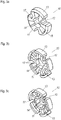
- FIGS Figures 3a to 3c three further exemplary embodiments of a brake device 10 according to the application are each shown in an isometric illustration.
- the basic structure of these braking devices 10 also corresponds to that of the second exemplary embodiment according to FIGS Figures 1b or 2b, the description of which is hereby explicitly referred to.
- the brake device 10 shown in the second embodiment 17 are three brake elements instead of the six brake elements 17 shown in the second embodiment 17 and correspondingly three inner cuts 15 and three outer cuts 12 are also provided.
- the brake device 10 shown could also be formed with only two brake elements 17, without the basic structure and the mode of operation being different (cf. also Fig. 13 ).
- FIG 4 A further embodiment of a braking device 10 according to the application is shown.
- this braking device 10 in addition to the spring action of the base body, a further spring element is present in order to increase the braking force of the braking device 10.
- the further spring element is a wrap spring 18 which is placed around the base body 11.
- one end 19 of the wrap spring 18 is bent. With this bent end 19, this side of the wrap spring can be fixed relative to the motor housing of the drive motor 1. The other end of the wrap spring 18 is free.
- the basic body 11 of the braking device 10 is only fixed in terms of its rotational position by the wrap spring 18 in the exemplary embodiment shown. This leads to the fact that when the base body 11 rotates due to its internal spring force on the axle shaft 5 of the drive motor 1 opens the wrap spring 18 in one direction of rotation, as a result of which the base body 11 can rotate in the wrap spring 18. In the opposite direction of rotation, the wrap spring 18 contracts when the base body 11 rotates, so that a braking action occurs between the base body 11 and the wrap spring 18, which also further compresses the base body 11 in addition to the internal spring force.
- the braking device 10 shown thus has different braking effects on the drive motor 1 depending on the direction of rotation.
- wrap spring 18 has two winding turns.
- a (wrap) spring can also have only one or less than one turn or more than two wraps.
- the outer incisions 12 and the inner incisions 15 in the base body 11 can be analogous to the exemplary embodiment according to FIG Figure 2c be designed obliquely to further reinforce the direction of rotation of the braking effect of the braking device 10.
- Figure 5 shows a further embodiment of a braking device 10 in an isometric view.
- the same reference numerals designate elements which are the same or have the same effect as in the preceding exemplary embodiments.
- the braking device 10 is in accordance with FIG Figure 5 constructed in two parts by the base body 11 being divided into two base body halves 11a, 11b. Each of the halves encloses a segment of the axle shaft 5 with a resilient arrangement of two sections 13 projecting outwards and three brake elements 17. The respective outer brake elements 17 merge into spring arms 20. The base body halves 11a, 11b are pressed onto the axle shaft 15 with the aid of the spring arms 20. Depending on the pressure exerted, the braking effect of the braking device 10 can be varied.
- a comprehensive spring can also be used here, for example in the manner of the wrap spring according to FIG Figure 4 , be provided to increase the braking force.
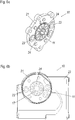
- FIGs 6a and 6b A further embodiment of a braking device 10 is shown in each case.
- the brake device 10 is formed integrally with a motor attachment, specifically in the embodiment of FIG Figure 6a integral with a motor mounting plate 21 and in the embodiment of FIG. 6b integrally with a motor mounting shell 22, which comprises a motor mounting plate 21.
- the motor mounting plate 21 serves to fasten a drive motor, for example the one in FIG Figure 1d shown drive motor 1, which rests with its flange plate 3 on the motor mounting plate 21.
- the motor mounting plate 21 has fastening holes 23 through which screws can be screwed into corresponding threaded holes in the flange plate 3 of the drive motor 1.
- a brake device 10 is integrated in the center of the motor mounting plate 21 in the motor mounting plate 21 and thus also the motor mounting shell 22.
- the braking device 10 is analogous to that in FIGS Figures 2a-c or. 3a-c Brake devices shown formed and is held via lateral webs 24 in the engine mounting plate 21 or the motor mounting shell 22.
- Motor bearing plate 21 or motor bearing shell 22 and the base body 11 of the braking device 10 and the webs 24 are preferably made in one piece from the same material, for example in a common injection molding process.
- the motor mounting plate 21 or motor mounting shell 22 can be designed as part or as a section of a housing of the electromotive drive or as a part or section of a transmission of the electromotive drive.
- Figure 7 shows a drive motor 1 with integrated braking devices 10.
- the drive motor 1 is shown in this illustration isometric and cut along its axis shaft 5.
- two braking devices 10 are integrated in the motor.
- a first braking device 10 is arranged in the area of a front bearing 4. This braking device 10 can, for example, according to the Figures 2b , 2c or 3 ac be trained.
- Another braking device 10 is arranged on the rear motor side opposite the worm 6 in a bearing dome 8. In alternative configurations, only one of the braking devices 10 can be integrated in the drive motor 1.
- the braking device 10 arranged in the rear engine area also takes on the function of a rear engine axle shaft bearing.
- a rear engine axle bearing is often designed as a plain bearing because of the relatively low radial forces that occur.
- the brake device 10 takes over the slide bearing function, but with the higher sliding friction provided in the application compared to a normal slide bearing.
- the assembly effort of the drive motor 1 with an integrated braking device 10 is identical to that with a sliding bearing, wherein in addition heat generation by the braking device 10 is kept away from the worm 6 and the associated transmission.
- Figure 8a shows an embodiment of a braking device 10, the braking effect can be adjusted externally.
- the braking device 10 corresponds to the Fig. 8a one of the in the Figures 2b , 2c or 3a-c shown braking devices 10.
- the Fig.8a is an extension of one of the inner incisions 15 of the base body 11 separated in the corresponding protruding section 13 by a cut, so that a gap 25 is formed. Due to the cut or the gap 25, the base body 11 of the braking device 10 can be widened or compressed during operation, as a result of which the braking forces exerted by the braking device 10 on an inserted axle shaft 5 can be changed. In order to be able to exert force more easily on the sections of the base body 11 adjacent to the gap 25, these can be made radially longer than the other sections of the base body 11.
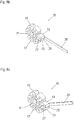
- At least one rotatable eccentric cam 27 can be arranged in at least one of the inner or outer incisions 12, 15, as this in the Figures 8b and 8c is shown.
- the rotatable cam 27 can be fastened, for example, to the end of a rotary actuating lever 26 which in turn is pivoted for rotating or pivoting the cam 27.
- the cam 27 is longer in cross section in one direction than in a transverse direction. In this elongated direction, the cam 27 is in a rest position, which in Figure 8b is shown, aligned parallel to the orientation of the incision 12, 15 in which it is arranged.
- the cam is dimensioned such that it is not in engagement with side walls of the cut 12, 15 in the rest position.
- the cam 27 is rotated out of the rest position, that is to say when the cam 27 "transversely" in the incision 12, 15, the cam with side flanks comes into engagement with the side walls of the incision 12, 15 and pries it up.
- This position of the cam 27 by operating the rotary operating lever 26 is in Figure 8c reproduced.
- the cam 27 is so narrow in a direction transverse to the direction in which it is elongated that in the rest position it cuts into the incision 12, 15 as it does in FIGS Figures 2b and 2c , 3a-c or 8a is shown can be introduced.
- the described actuation of the braking device 10 via the cams 27 described can be used, for example, to enable rapid adjustment of the furniture drive via an external force and, if necessary, emergency adjustment in the currentless state of the furniture drive.
- the rotary actuating lever 26 carrying the cam 27 can be actuated manually or externally on the housing of the furniture drive via a linkage.
- a Bowden cable is also suitable for power transmission.
- the gear unit of a furniture drive downstream of the drive motor for example the worm gear and a spindle drive
- the braking device 10 released in this way can be adjusted quickly or emergency adjustment can be used.
- an eccentric or wedge or pliers-like mechanism engaging in one of the incisions 12, 15 can generally be used to release the braking device 10.
- the braking device 10 comprises a base body 11, which in turn is in terms of its basic structure with those of the Figures 2a , b , c and 3a, b is comparable.
- a rotary actuation device 28 is in engagement with the base body 11, the basic structure of which is also annular, the axle shaft to be braked by the brake device 10 leading centrally through the rotary actuation device 28.
- a plurality of spreading elements 29 are formed all around on a surface of the rotary actuation device 28 facing the base body 11.
- Figure 9a shows an isometric top view of the base body 11 in the foreground and the rotary actuating device 28 which engages in the base body 11 from behind from this viewing direction
- Figure 9b is an isometric sectional view of the arrangement of the base body 11 and rotary actuator 28 shown, wherein in Figure 9b only the expansion elements 29 are visible from the rotary actuation device 28. In this view, the the rear of the base body 11 facing the rotary actuation device 28 and the shape of the expansion elements 29 are visible.
- the outer projecting sections 13 project axially beyond the inner part of the base body 11, so that a projecting edge is formed by the projecting sections 13.
- This edge is provided with a run-up slope 30 in the area of the projecting sections 13.
- the spreading elements 29 are formed eccentrically on their radially outward-facing side.
- the shape of the expansion element 29 and the run-up slope 30 leads to a spreading of the base body 11 when the base body 11 is rotated relative to the rotary actuation device 28. A relative rotary movement of these two elements to one another can thus be used to spread the base body 11 more or less, thereby reducing the braking effect is varied on an axis shaft leading through the base body 11.
- FIG. 10 A further exemplary embodiment of a braking device 10 is specified, which is the same in the exemplary embodiment of FIG Figures 9a and 9b exploited principle.
- a braking device is similar to that in Figure 6b integrated in a motor bearing shell 22 with motor bearing plate 21.
- the drive motor 1 is attached to the motor mounting plate 21 from behind, so that its axle shaft 5 with the worm 6 protrudes forward in the figure shown.
- the braking device 10 is guided with its base body 11 from the front over the axle shaft 5 and is received in a recess in the engine mounting plate 21.
- compression elements 31 are formed on the outer circumference of the receptacle of the base body 11 on the engine mounting plate 21 instead of the expansion element 29. Analogous to the expansion elements 29, the compression elements 31 are also designed eccentrically with regard to their radial course.
- bevels 30 are formed on the base body 11. Depending on the direction of rotation of the axle shaft guided through the base body 11 of the braking device 10, a torque is exerted on the base body 11, which leads to a rotation of the base body 11 with respect to the compression elements 31. The base body 11 can move in a direction of rotation of the axle shaft relax until it only brakes the axle shaft with its spring force. In the other direction of rotation, the base body 11 is compressed by the run-up bevels 30 on the compression elements 31, which increases the braking effect.
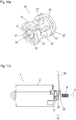
- FIG. 11a shows the braking device 10 separately from an drive motor in an isometric illustration.
- Figure 11b finally shows the braking device 20 in interaction with a drive motor 1.
- the braking device 10 shown also includes the one shown in FIG Figure 11a or 11b shown braking device 10 has a base body 11 which cooperates with an actuating device.
- the actuating device is designed as an axial actuating device 32 which is displaced in relation to the base body 11 in order to change the braking effect in the axial direction.
- the axial actuating device 32 is in turn constructed in a ring shape with a disk-like base 33, the axial actuating device 32 with its base being arranged essentially parallel to the base body 11 together on the axle shaft 5 to be braked.
- the base 33 is provided with a circumferential groove 34 into which a pivot lever 36 engages with a U-shaped fork in order to be able to move the actuating device 32 axially on the axle shaft 5.
- the mandrels 35 are conically shaped. They taper from the base 33 to the free end. When the mandrels 35 engage in the inner incisions 15, they spread the base body 11 evenly over its entire circumference, and the more so, the further the mandrels 35 are pushed into the base body 11.
- FIGS Figures 12a-d A further exemplary embodiment of a braking device 10 which automatically varies the braking force as a function of the direction of rotation is shown in FIGS Figures 12a-d shown.
- the Figures 12a and 12b show the braking device 10 arranged on an axle shaft 5 of a drive motor 1 in each case in an isometric representation.
- the braking device 10 is in the Figure 12a partially shown transparently and at Figure 12b partially cut.
- Figures 12c and d sections through the area of the braking device 10 are shown, which the braking device 10 reproduces in different directions of rotation of the axle shaft 5 of the drive motor 1.
- the braking device 10 comprises a basic body 11, which is comparable to the basic bodies 11 of the braking device 10 according to FIG Figure 3a is trained.
- An embodiment with more than the three protruding sections 13 shown here is also conceivable.
- the base body 11 is held in a common cage 38 parallel to a control disk 37 of comparable design.
- the common cage 38 fixes the base body 11 and the control disk 37 at a distance from one another in parallel and in a rotationally fixed manner to one another.
- the control disk 37 like the base body 11, has braking surfaces which are pressed resiliently onto the axle shaft 5. However, the braking forces exerted by the control disk 37 on the axle shaft 5 are smaller than those of the base body 11.
- the base body 11 and the control disk 37 are designed for different axle diameters.
- the axle shaft 5 is profiled in the axle section 7, in which the braking device 10 acts, in such a way that a control section 7a in the area of the control disk 37 has a smaller diameter than a braking section 7c, which is assigned to the base body 11.
- Control section 7a and braking section 7c merge into one another in a conical section, hereinafter referred to as freewheeling section 7b.
- the profiling of the axle section 7 in the three sections 7a-c mentioned is in the Figures 12c and 12d evident.
- the cage 38 is arranged in a hollow cylindrical receptacle 41 of a motor mount 40, in which the cage 38 can rotate and which it can move axially by a certain displacement.
- a threaded web 42 is formed on the circumference, projecting inward, into the oblique groove 39 of the cage 38 engages.
- the two sectional images of the Figures 12c and d differ in the direction of rotation of the motor shaft 5, which is symbolized by an arrow indicating the direction of rotation.
- the cage 38 is positioned maximally in the hollow cylindrical receptacle 41 (to the left in the figure).
- the control disk 37 is in contact with the control section 7a of the axle shaft 5 and experiences a corresponding torque, by means of which the cage 38 is held in the position shown.
- the base body 11 is positioned by the cage 38 in such a way that it is wholly or at least partially in the conical freewheel section 7b of the axle shaft 5.
- the base body 11 thus experiences no or only a very slight braking effect. Overall, there is only a small braking effect on the axle shaft 5 in this direction of rotation of the axle shaft 5.
- FIG 13 shows a further embodiment of a brake device 10 according to the application.
- the brake device 10 is shown in an isometric representation placed on an axle shaft 5 of a drive motor 1.
- the braking device 10 has a loop-shaped base body 11 on, which provides two approximately semicircular braking elements 17 in a central area, which act on an axle section 7 of the axle shaft 5.
- the two brake elements 17 are pressed towards one another via two lateral arcuate spring sections, as a result of which the braking effect on the axle shaft 6 results.
- the braking device 10 thus corresponds approximately to that of the braking devices from FIGS Figures 2a-c and 3a and b .
- brake elements 17 and the spring sections which cause the resilient action are made of the same material and in one piece.
- As material for the braking device 10 of the Figure 15 comes in addition to a plastic, a metal, such as zinc, z. B. in the form of die-cast zinc, or aluminum or steel in question.
- braking device 10 is similar to that in Figure 3a and 3b shown.
- Inner and outer incisions 15, 12 are again made in a base body 11, but in such a way that the sides of the incision do not run parallel to one another, but rather the remaining material of the base body 11, that is to say the inner part of the base body 11 or the protruding portions 13, are each the same Have material thickness. This creates a structure that more closely corresponds to a selected band that is closed into a ring.
- the braking device 10 of the Figure 14 could act directly on an axis with the inward-facing brake elements 17 of the base body 11 used as braking surfaces.
- three ring segments 43 are used, which are held in the base body 11 in a rotationally fixed manner and which provide braking surfaces on their inside.
- the material of the braking surfaces can be selected independently of the material of the base body 11. This makes it possible, for example, to use a material that is as hard as possible, but not necessarily as resilient, for the braking surfaces relative to the base body 11.
- Figure 15 shows a braking device 10 integrated in a motor bearing shell 21, which is comparable in terms of its basic structure to that in FIG Figure 6 brake device 10 shown.
- ring segments 43 are also placed on the inside of the brake elements 17, which can be made of a different material than the base body 11 of the brake device 10 or the motor bearing shell 21. If necessary, the ring segments 43 can be formed in one piece with the motor bearing shell 21 or the base body 11, for example in a multi-component injection molding process. It is also possible to initially manufacture the ring segments 43 separately and then to insert the motor bearing shell 21 onto the ring segments 43 when inserted into the injection mold of the motor bearing shell 21.
Landscapes
- Engineering & Computer Science (AREA)
- General Engineering & Computer Science (AREA)
- Power Engineering (AREA)
- Mechanical Engineering (AREA)
- Braking Arrangements (AREA)
- Connection Of Motors, Electrical Generators, Mechanical Devices, And The Like (AREA)
Claims (15)
- Dispositif de freinage (10) pour un moteur d'entraînement électrique (1), en particulier un moteur d'entraînement (2) avec un arbre d'induit (5) qui dépasse dans un carter de moteur (2), qui comporte au moins un élément de freinage (17) et un accumulateur de force, lequel accumulateur de force soumet de façon permanente une surface de frottement de l'élément de freinage à un effort de freinage, caractérisé en ce que l'accumulateur de force et l'élément de freinage (17) sont formés d'un seul tenant du même matériau.
- Dispositif de freinage (10) selon la revendication 1, présentant un corps de base (11) annulaire qui est fermé sur sa circonférence au moins dans une région extérieure.
- Dispositif de freinage (10) selon la revendication 2, présentant une ouverture centrale (14), avec des surfaces intérieures qui forment les surfaces de frottement du dispositif de freinage (10).
- Dispositif de freinage (10) selon la revendication 2 ou 3, présentant au moins une encoche (15) qui est formée dans le corps de base (11) à partir de l'ouverture centrale (14).
- Dispositif de freinage (10) selon l'une des revendications 2 à 4, présentant au moins une autre encoche (12) qui est formée dans le corps de base (11) à partir d'une circonférence extérieure du corps de base (11).
- Dispositif de freinage (10) selon la revendication 4 ou 5, dans lequel le corps de base (11) présente plusieurs encoches (12) et/ou plusieurs autres encoches (15) qui sont disposées en étoile.
- Dispositif de freinage (10) selon la revendication 6, dans lequel le corps de base (11) présente plusieurs encoches (12) et plusieurs autres encoches (15), les encoches (12) et les autres encoches (15) étant alternées sur la circonférence.
- Dispositif de freinage (10) selon l'une des revendications 4 à 7, dans lequel le corps de base (11) est fait d'une tôle, les encoches (15) formant entre elles des languettes de ressort (16) qui présentent à leur extrémité libre une section orientée dans le sens axial dont la surface forme la surface de frottement.
- Dispositif de freinage (10) selon l'une des revendications 4 à 7, dans lequel le corps de base (11) est fabriqué en forme de disque à partir d'un matériau massif.
- Dispositif de freinage (10) selon la revendication 9, dans lequel le corps de base (11) se compose de zinc, de bronze ou de PEEK.
- Dispositif de freinage (10) selon la revendication 8 ou 9, dans lequel une surface de l'au moins un élément de freinage (17) forme la surface de frottement.
- Dispositif de freinage (10) selon la revendication 8 ou 9, dans lequel au moins un segment d'anneau supplémentaire (43) est disposé sur l'au moins un élément de freinage (17) et tourné vers l'ouverture centrale (14), une surface du segment d'anneau (43) formant la surface de frottement.
- Dispositif de freinage (10) selon l'une des revendications 1 à 12, formé d'un seul tenant avec une plaque d'appui du moteur (21).
- Dispositif de freinage (10) selon l'une des revendications 1 à 12, qui est intégré dans un moteur d'entraînement (1) électrique.
- Dispositif de freinage (10) selon la revendication 14, qui est conformé comme un palier de glissement pour l'arbre menant (5) du moteur d'entraînement (1) électrique.
Applications Claiming Priority (2)
| Application Number | Priority Date | Filing Date | Title |
|---|---|---|---|
| DE202015103948 | 2015-07-28 | ||
| PCT/EP2015/081152 WO2017016618A1 (fr) | 2015-07-28 | 2015-12-23 | Dispositif de freinage pour moteur électrique d'entraînement |
Publications (2)
| Publication Number | Publication Date |
|---|---|
| EP3329580A1 EP3329580A1 (fr) | 2018-06-06 |
| EP3329580B1 true EP3329580B1 (fr) | 2020-07-29 |
Family
ID=55072637
Family Applications (1)
| Application Number | Title | Priority Date | Filing Date |
|---|---|---|---|
| EP15820859.5A Active EP3329580B1 (fr) | 2015-07-28 | 2015-12-23 | Dispositif de freinage pour moteur électrique d'entraînement |
Country Status (7)
| Country | Link |
|---|---|
| US (2) | US11411464B2 (fr) |
| EP (1) | EP3329580B1 (fr) |
| CN (3) | CN107925309B (fr) |
| DE (1) | DE202015107053U1 (fr) |
| DK (1) | DK3329580T3 (fr) |
| ES (1) | ES2821946T3 (fr) |
| WO (1) | WO2017016618A1 (fr) |
Cited By (1)
| Publication number | Priority date | Publication date | Assignee | Title |
|---|---|---|---|---|
| EP4210205A4 (fr) * | 2021-03-16 | 2024-04-24 | Zhejiang Jiecang Linear Motion Technology Co., Ltd | Dispositif d'entraînement à auto-verrouillage unidirectionnel |
Families Citing this family (9)
| Publication number | Priority date | Publication date | Assignee | Title |
|---|---|---|---|---|
| US11411464B2 (en) * | 2015-07-28 | 2022-08-09 | Dewertokin Technology Group Co., Ltd. | Braking device for an electric drive motor |
| JP6472375B2 (ja) | 2015-12-25 | 2019-02-20 | ミネベアミツミ株式会社 | モータ |
| DK3596808T3 (da) | 2017-03-14 | 2021-08-30 | Dewertokin Tech Group Co Ltd | Elektromotorisk møbeldrev med en drivmotor med bremseindretning |
| AT520949B1 (de) * | 2018-03-06 | 2019-11-15 | Traktionssysteme Austria Gmbh | Fixierelement zur Fixierung der Rotorwelle einer elektrischen Maschine an deren Stator, sowie elektrische Maschine mit einem solchen Fixierelement |
| AT524824B1 (de) * | 2021-02-23 | 2025-08-15 | Trumpf Maschinen Austria Gmbh & Co Kg | Elektromechanischer Spindelantrieb |
| DE202021101238U1 (de) | 2021-03-11 | 2021-03-17 | Dewertokin Technology Group Co., Ltd. | Möbelantrieb mit einem elektrischen Antriebsmotor mit einer Bremsvorrichtung |
| CN113651271B (zh) * | 2021-07-07 | 2023-01-06 | 浙江捷昌线性驱动科技股份有限公司 | 马达自锁机构及线性致动器 |
| CN114629292A (zh) * | 2022-03-08 | 2022-06-14 | 舟山市东海电机实业有限公司 | 一种制动摩擦力可调节的刹车电机 |
| CN117128262A (zh) * | 2023-08-28 | 2023-11-28 | 南京中车浦镇海泰制动设备有限公司 | 前置式手动复位机构 |
Family Cites Families (38)
| Publication number | Priority date | Publication date | Assignee | Title |
|---|---|---|---|---|
| US2490456A (en) * | 1947-09-16 | 1949-12-06 | Floyd E Niederhiser | Motor and brake device |
| US3826934A (en) * | 1972-09-25 | 1974-07-30 | Gen Electric | Nonreversible motor |
| JP3662353B2 (ja) * | 1996-08-05 | 2005-06-22 | 加藤電機株式会社 | チルトヒンジ |
| US6256838B1 (en) * | 2000-01-25 | 2001-07-10 | Lu Sheng-Nan | Pivoting assembly for a notebook computer |
| US6376948B1 (en) * | 2000-03-30 | 2002-04-23 | Chin-Tsang Wang | Motor-synchronous exciting brake |
| US6550599B2 (en) * | 2000-06-06 | 2003-04-22 | Asmo Co., Ltd. | Motor having clutch and manufacturing method thereof |
| TW448989U (en) * | 2001-01-16 | 2001-08-01 | Lumens Technology Inc | Hinge structure for retractable arm |
| AU2003273793A1 (en) * | 2002-10-30 | 2004-05-25 | Linak A/S | An actuator |
| US6814209B1 (en) * | 2003-05-29 | 2004-11-09 | Siemens Vdo Automotive Corporation | Inertia clutch mechanism in motors to prevent backdrive |
| US6740997B1 (en) * | 2003-08-19 | 2004-05-25 | Cheng Hsian Chen | Front brake of an electric motor |
| DE202004008714U1 (de) | 2004-05-28 | 2004-07-29 | Dewert Antriebs- Und Systemtechnik Gmbh & Co Kg | Bremsvorrichtung für einen elektrischen Antriebsmotor und Möbel |
| DE202004008713U1 (de) | 2004-05-28 | 2004-07-29 | Dewert Antriebs- Und Systemtechnik Gmbh & Co Kg | Bremsvorrichtung für einen elektrischen Antriebsmotor und Möbel |
| CN2822011Y (zh) * | 2005-08-19 | 2006-09-27 | 姚培德 | 管状电机的刹车装置 |
| CN2833998Y (zh) * | 2005-09-20 | 2006-11-01 | 姚培德 | 管状电机的制动器 |
| US7538461B2 (en) * | 2005-12-20 | 2009-05-26 | Mcmillan Electric Company | Brake mechanism for electric motor |
| DE202006018505U1 (de) | 2006-12-05 | 2008-04-17 | Dewert Antriebs- Und Systemtechnik Gmbh | Elektromotorischer Linearantrieb |
| US7728475B2 (en) * | 2007-02-20 | 2010-06-01 | Hamilton Sundstrand Corporation | Thermally operated rotatable component restraint system |
| DE102007023712B4 (de) * | 2007-05-22 | 2010-12-30 | Bühler Motor GmbH | Antrieb mit einem Elektromotor, einem Gehäuse und einer richtungsabhängigen Bremse |
| DE102007034481A1 (de) * | 2007-07-20 | 2009-01-22 | Huf Hülsbeck & Fürst Gmbh & Co. Kg | Verriegelungsvorrichtung mit Arretierungsteil |
| JP5081601B2 (ja) * | 2007-12-13 | 2012-11-28 | アスモ株式会社 | ブレーキ装置及び減速機構付モータ |
| DE102008030738A1 (de) * | 2008-06-27 | 2009-12-31 | Valeo Systèmes d'Essuyage | Elektromotorischer Hilfsantrieb für Fahrzeuge |
| TW201020406A (en) * | 2008-11-24 | 2010-06-01 | First Dome Corp | Pivot mechanism and electrical apparatus applying the same |
| JP5297993B2 (ja) * | 2009-06-23 | 2013-09-25 | アスモ株式会社 | クラッチ及びモータ |
| FR2946997B1 (fr) * | 2009-06-23 | 2011-07-08 | Somfy Sas | Actionneur electrique d'entrainement d'un ecran domotique |
| DE102009037068A1 (de) * | 2009-08-13 | 2011-02-17 | GM Global Technology Operations, Inc., Detroit | Lagerbuchse insbesondere für ein Schaltungsgehäuse eines Fahrzeugs und Verfahren zur Montage der Lagerbuchse |
| FR2971827B1 (fr) * | 2011-02-23 | 2013-02-15 | Sofineco | Dispositif de freinage electrique d'un arbre d'entrainement |
| DE102011050194A1 (de) | 2011-05-06 | 2012-11-08 | Dewert Antriebs- Und Systemtechnik Gmbh | Elektromotorischer Möbelantrieb mit einer Energieversorgungseinrichtung |
| TWI459691B (zh) * | 2011-12-30 | 2014-11-01 | Timotion Technology Co Ltd | 用於致動裝置之具制動功能的馬達 |
| JP5955237B2 (ja) * | 2012-07-06 | 2016-07-20 | 三菱電機株式会社 | ブレーキ付き回転電機 |
| US9004240B2 (en) * | 2013-02-27 | 2015-04-14 | Integran Technologies Inc. | Friction liner |
| US8994236B2 (en) * | 2013-02-28 | 2015-03-31 | Ford Global Technologies, Llc | Electromagnetically actuated axial one-way clutch |
| DE102013005287A1 (de) * | 2013-03-27 | 2014-10-02 | Andreas Stihl Ag & Co. Kg | Handgeführtes Arbeitsgerät und Verfahren zur Herstellung einer Bremseinrichtung eines handgeführten Arbeitsgeräts |
| US9937841B2 (en) * | 2014-03-18 | 2018-04-10 | B/E Aerospace, Inc. | Friction bushing |
| CN203827112U (zh) * | 2014-05-05 | 2014-09-10 | 山东十方机电有限公司 | 一种刹车灵活稳定的新型管状电机 |
| JP6339933B2 (ja) * | 2014-12-26 | 2018-06-06 | オリエンタルモーター株式会社 | 摩擦ブレーキ構造 |
| US11411464B2 (en) * | 2015-07-28 | 2022-08-09 | Dewertokin Technology Group Co., Ltd. | Braking device for an electric drive motor |
| CN110323892B (zh) * | 2018-03-29 | 2020-07-28 | 台达电子工业股份有限公司 | 马达刹车模块 |
| US20220281124A1 (en) * | 2021-03-02 | 2022-09-08 | Kinova Inc. | Brake system for articulated mechanism |
-
2015
- 2015-12-23 US US15/748,043 patent/US11411464B2/en active Active
- 2015-12-23 CN CN201580082056.9A patent/CN107925309B/zh active Active
- 2015-12-23 WO PCT/EP2015/081152 patent/WO2017016618A1/fr not_active Ceased
- 2015-12-23 CN CN202011585049.XA patent/CN112769286B/zh active Active
- 2015-12-23 ES ES15820859T patent/ES2821946T3/es active Active
- 2015-12-23 CN CN202011585113.4A patent/CN112769287B/zh active Active
- 2015-12-23 DK DK15820859.5T patent/DK3329580T3/da active
- 2015-12-23 DE DE202015107053.5U patent/DE202015107053U1/de not_active Expired - Lifetime
- 2015-12-23 EP EP15820859.5A patent/EP3329580B1/fr active Active
-
2022
- 2022-06-16 US US17/842,311 patent/US11799355B2/en active Active
Non-Patent Citations (1)
| Title |
|---|
| None * |
Cited By (2)
| Publication number | Priority date | Publication date | Assignee | Title |
|---|---|---|---|---|
| EP4210205A4 (fr) * | 2021-03-16 | 2024-04-24 | Zhejiang Jiecang Linear Motion Technology Co., Ltd | Dispositif d'entraînement à auto-verrouillage unidirectionnel |
| US12323036B2 (en) | 2021-03-16 | 2025-06-03 | Zhejiang Jiecang Linear Motion Technology Co., Ltd. | Rotating self-locking actuator |
Also Published As
| Publication number | Publication date |
|---|---|
| CN112769287A (zh) | 2021-05-07 |
| CN112769286B (zh) | 2023-12-15 |
| DK3329580T3 (da) | 2020-10-19 |
| CN112769286A (zh) | 2021-05-07 |
| DE202015107053U1 (de) | 2016-02-01 |
| CN112769287B (zh) | 2023-11-21 |
| WO2017016618A1 (fr) | 2017-02-02 |
| CN107925309A (zh) | 2018-04-17 |
| US11799355B2 (en) | 2023-10-24 |
| US11411464B2 (en) | 2022-08-09 |
| EP3329580A1 (fr) | 2018-06-06 |
| CN107925309B (zh) | 2021-01-12 |
| US20180219453A1 (en) | 2018-08-02 |
| ES2821946T3 (es) | 2021-04-28 |
| US20220311308A1 (en) | 2022-09-29 |
Similar Documents
| Publication | Publication Date | Title |
|---|---|---|
| EP3329580B1 (fr) | Dispositif de freinage pour moteur électrique d'entraînement | |
| EP2222977B1 (fr) | Frein à friction électromécanique | |
| EP2682635B1 (fr) | Mécanisme d'actionnement de frein pour frein à disque | |
| WO1999004933A2 (fr) | Accouplement a securite antisurcharge | |
| DE102012103017A1 (de) | Lagerung eines eine teilzylindrische Außenfläche aufweisenden Drehhebels gegenüber einem Druckstück | |
| EP1455106A1 (fr) | Systéme de débrayage | |
| EP3596808B1 (fr) | Entraînement de meuble à moteur électrique doté d'un moteur d'entraînement équipé d'un dispositif de freinage | |
| EP3261902B1 (fr) | Dispositif de blocage d'une colonne de direction réglable de véhicule automobile | |
| EP1971791B1 (fr) | Mecanisme roue libre de debrayage et frein electromecanique de vehicule pourvu du mecanisme roue libre de debrayage | |
| DE102011108977B4 (de) | Aktuator, insbesondere für einenFahrzeugsitz | |
| EP0557283B1 (fr) | Dispositif de rattrapage de jeu automatique pour frein a disque | |
| EP4305322B1 (fr) | Dispositif moteur pour meubles avec un electromoteur avec frein | |
| EP2748028B1 (fr) | Ferrure de réglage pourvue d'un système de blocage axial destiné à sécuriser le fonctionnement | |
| EP2878844B1 (fr) | Frein à disque | |
| EP2995826A2 (fr) | Pivot | |
| DE102006020550A1 (de) | Bremsmechanismus für eine Scheibenbremse | |
| EP2838756A1 (fr) | Dispositif de freinage pour un ensemble engrenage épicycloïdal à activation électromécanique directe d'un mécanisme de réglage de siège et procédé de fonctionnement d'un dispositif de freinage | |
| EP1952043B1 (fr) | Frein electromecanique sans jeu | |
| DE102019111222A1 (de) | Luftleitvorrichtung mit Bremseinrichtung | |
| EP1400190B1 (fr) | Entraînement électromoteur pour meuble | |
| WO2018192600A1 (fr) | Mécanisme fileté à roulement | |
| DE3148566A1 (de) | Innenbacken-trommelbremse | |
| DE102017120988B3 (de) | Klemmgesperre | |
| DE102006000763B3 (de) | Elektromechanische Bremse mit Notöffnungseinrichtung | |
| EP3510300B1 (fr) | Dispositif de rattrapage de jeu pour système de freinage |
Legal Events
| Date | Code | Title | Description |
|---|---|---|---|
| STAA | Information on the status of an ep patent application or granted ep patent |
Free format text: STATUS: THE INTERNATIONAL PUBLICATION HAS BEEN MADE |
|
| PUAI | Public reference made under article 153(3) epc to a published international application that has entered the european phase |
Free format text: ORIGINAL CODE: 0009012 |
|
| STAA | Information on the status of an ep patent application or granted ep patent |
Free format text: STATUS: REQUEST FOR EXAMINATION WAS MADE |
|
| 17P | Request for examination filed |
Effective date: 20180130 |
|
| AK | Designated contracting states |
Kind code of ref document: A1 Designated state(s): AL AT BE BG CH CY CZ DE DK EE ES FI FR GB GR HR HU IE IS IT LI LT LU LV MC MK MT NL NO PL PT RO RS SE SI SK SM TR |
|
| AX | Request for extension of the european patent |
Extension state: BA ME |
|
| DAV | Request for validation of the european patent (deleted) | ||
| DAX | Request for extension of the european patent (deleted) | ||
| GRAP | Despatch of communication of intention to grant a patent |
Free format text: ORIGINAL CODE: EPIDOSNIGR1 |
|
| STAA | Information on the status of an ep patent application or granted ep patent |
Free format text: STATUS: GRANT OF PATENT IS INTENDED |
|
| RIC1 | Information provided on ipc code assigned before grant |
Ipc: H02K 7/116 20060101ALI20200122BHEP Ipc: H02K 7/102 20060101AFI20200122BHEP |
|
| INTG | Intention to grant announced |
Effective date: 20200217 |
|
| RIN1 | Information on inventor provided before grant (corrected) |
Inventor name: MUELLER, CHRISTIAN Inventor name: KUHN, CHRISTIN Inventor name: MUELLER, SVEN |
|
| GRAS | Grant fee paid |
Free format text: ORIGINAL CODE: EPIDOSNIGR3 |
|
| GRAA | (expected) grant |
Free format text: ORIGINAL CODE: 0009210 |
|
| STAA | Information on the status of an ep patent application or granted ep patent |
Free format text: STATUS: THE PATENT HAS BEEN GRANTED |
|
| AK | Designated contracting states |
Kind code of ref document: B1 Designated state(s): AL AT BE BG CH CY CZ DE DK EE ES FI FR GB GR HR HU IE IS IT LI LT LU LV MC MK MT NL NO PL PT RO RS SE SI SK SM TR |
|
| REG | Reference to a national code |
Ref country code: CH Ref legal event code: EP |
|
| REG | Reference to a national code |
Ref country code: DE Ref legal event code: R096 Ref document number: 502015013136 Country of ref document: DE |
|
| REG | Reference to a national code |
Ref country code: AT Ref legal event code: REF Ref document number: 1296939 Country of ref document: AT Kind code of ref document: T Effective date: 20200815 |
|
| REG | Reference to a national code |
Ref country code: IE Ref legal event code: FG4D Free format text: LANGUAGE OF EP DOCUMENT: GERMAN |
|
| REG | Reference to a national code |
Ref country code: NL Ref legal event code: FP |
|
| REG | Reference to a national code |
Ref country code: SE Ref legal event code: TRGR |
|
| REG | Reference to a national code |
Ref country code: DK Ref legal event code: T3 Effective date: 20201014 |
|
| REG | Reference to a national code |
Ref country code: LT Ref legal event code: MG4D |
|
| PG25 | Lapsed in a contracting state [announced via postgrant information from national office to epo] |
Ref country code: BG Free format text: LAPSE BECAUSE OF FAILURE TO SUBMIT A TRANSLATION OF THE DESCRIPTION OR TO PAY THE FEE WITHIN THE PRESCRIBED TIME-LIMIT Effective date: 20201029 Ref country code: GR Free format text: LAPSE BECAUSE OF FAILURE TO SUBMIT A TRANSLATION OF THE DESCRIPTION OR TO PAY THE FEE WITHIN THE PRESCRIBED TIME-LIMIT Effective date: 20201030 Ref country code: LT Free format text: LAPSE BECAUSE OF FAILURE TO SUBMIT A TRANSLATION OF THE DESCRIPTION OR TO PAY THE FEE WITHIN THE PRESCRIBED TIME-LIMIT Effective date: 20200729 Ref country code: FI Free format text: LAPSE BECAUSE OF FAILURE TO SUBMIT A TRANSLATION OF THE DESCRIPTION OR TO PAY THE FEE WITHIN THE PRESCRIBED TIME-LIMIT Effective date: 20200729 Ref country code: PT Free format text: LAPSE BECAUSE OF FAILURE TO SUBMIT A TRANSLATION OF THE DESCRIPTION OR TO PAY THE FEE WITHIN THE PRESCRIBED TIME-LIMIT Effective date: 20201130 Ref country code: HR Free format text: LAPSE BECAUSE OF FAILURE TO SUBMIT A TRANSLATION OF THE DESCRIPTION OR TO PAY THE FEE WITHIN THE PRESCRIBED TIME-LIMIT Effective date: 20200729 Ref country code: NO Free format text: LAPSE BECAUSE OF FAILURE TO SUBMIT A TRANSLATION OF THE DESCRIPTION OR TO PAY THE FEE WITHIN THE PRESCRIBED TIME-LIMIT Effective date: 20201029 |
|
| PG25 | Lapsed in a contracting state [announced via postgrant information from national office to epo] |
Ref country code: IS Free format text: LAPSE BECAUSE OF FAILURE TO SUBMIT A TRANSLATION OF THE DESCRIPTION OR TO PAY THE FEE WITHIN THE PRESCRIBED TIME-LIMIT Effective date: 20201129 Ref country code: RS Free format text: LAPSE BECAUSE OF FAILURE TO SUBMIT A TRANSLATION OF THE DESCRIPTION OR TO PAY THE FEE WITHIN THE PRESCRIBED TIME-LIMIT Effective date: 20200729 Ref country code: PL Free format text: LAPSE BECAUSE OF FAILURE TO SUBMIT A TRANSLATION OF THE DESCRIPTION OR TO PAY THE FEE WITHIN THE PRESCRIBED TIME-LIMIT Effective date: 20200729 Ref country code: LV Free format text: LAPSE BECAUSE OF FAILURE TO SUBMIT A TRANSLATION OF THE DESCRIPTION OR TO PAY THE FEE WITHIN THE PRESCRIBED TIME-LIMIT Effective date: 20200729 |
|
| REG | Reference to a national code |
Ref country code: DE Ref legal event code: R082 Ref document number: 502015013136 Country of ref document: DE Representative=s name: PATENT- UND RECHTSANWAELTE LOESENBECK, SPECHT,, DE Ref country code: DE Ref legal event code: R081 Ref document number: 502015013136 Country of ref document: DE Owner name: DEWERTOKIN TECHNOLOGY GROUP CO., LTD., JIAXING, CN Free format text: FORMER OWNER: DEWERTOKIN GMBH, 32278 KIRCHLENGERN, DE |
|
| REG | Reference to a national code |
Ref country code: ES Ref legal event code: FG2A Ref document number: 2821946 Country of ref document: ES Kind code of ref document: T3 Effective date: 20210428 |
|
| PG25 | Lapsed in a contracting state [announced via postgrant information from national office to epo] |
Ref country code: RO Free format text: LAPSE BECAUSE OF FAILURE TO SUBMIT A TRANSLATION OF THE DESCRIPTION OR TO PAY THE FEE WITHIN THE PRESCRIBED TIME-LIMIT Effective date: 20200729 Ref country code: SM Free format text: LAPSE BECAUSE OF FAILURE TO SUBMIT A TRANSLATION OF THE DESCRIPTION OR TO PAY THE FEE WITHIN THE PRESCRIBED TIME-LIMIT Effective date: 20200729 Ref country code: EE Free format text: LAPSE BECAUSE OF FAILURE TO SUBMIT A TRANSLATION OF THE DESCRIPTION OR TO PAY THE FEE WITHIN THE PRESCRIBED TIME-LIMIT Effective date: 20200729 |
|
| REG | Reference to a national code |
Ref country code: DE Ref legal event code: R097 Ref document number: 502015013136 Country of ref document: DE |
|
| PG25 | Lapsed in a contracting state [announced via postgrant information from national office to epo] |
Ref country code: AL Free format text: LAPSE BECAUSE OF FAILURE TO SUBMIT A TRANSLATION OF THE DESCRIPTION OR TO PAY THE FEE WITHIN THE PRESCRIBED TIME-LIMIT Effective date: 20200729 |
|
| PLBE | No opposition filed within time limit |
Free format text: ORIGINAL CODE: 0009261 |
|
| STAA | Information on the status of an ep patent application or granted ep patent |
Free format text: STATUS: NO OPPOSITION FILED WITHIN TIME LIMIT |
|
| PG25 | Lapsed in a contracting state [announced via postgrant information from national office to epo] |
Ref country code: SK Free format text: LAPSE BECAUSE OF FAILURE TO SUBMIT A TRANSLATION OF THE DESCRIPTION OR TO PAY THE FEE WITHIN THE PRESCRIBED TIME-LIMIT Effective date: 20200729 |
|
| REG | Reference to a national code |
Ref country code: NL Ref legal event code: PD Owner name: DEWERTOKIN TECHNOLOGY GROUP CO., LTD; CN Free format text: DETAILS ASSIGNMENT: CHANGE OF OWNER(S), ASSIGNMENT; FORMER OWNER NAME: DEWERTOKIN GMBH Effective date: 20210607 |
|
| 26N | No opposition filed |
Effective date: 20210430 |
|
| REG | Reference to a national code |
Ref country code: GB Ref legal event code: 732E Free format text: REGISTERED BETWEEN 20210701 AND 20210707 |
|
| REG | Reference to a national code |
Ref country code: CH Ref legal event code: PL |
|
| REG | Reference to a national code |
Ref country code: ES Ref legal event code: PC2A Owner name: DEWERTOKIN TECHNOLOGY GROUP CO., LTD. Effective date: 20210816 |
|
| PG25 | Lapsed in a contracting state [announced via postgrant information from national office to epo] |
Ref country code: SI Free format text: LAPSE BECAUSE OF FAILURE TO SUBMIT A TRANSLATION OF THE DESCRIPTION OR TO PAY THE FEE WITHIN THE PRESCRIBED TIME-LIMIT Effective date: 20200729 Ref country code: MC Free format text: LAPSE BECAUSE OF FAILURE TO SUBMIT A TRANSLATION OF THE DESCRIPTION OR TO PAY THE FEE WITHIN THE PRESCRIBED TIME-LIMIT Effective date: 20200729 |
|
| REG | Reference to a national code |
Ref country code: BE Ref legal event code: MM Effective date: 20201231 |
|
| PG25 | Lapsed in a contracting state [announced via postgrant information from national office to epo] |
Ref country code: LU Free format text: LAPSE BECAUSE OF NON-PAYMENT OF DUE FEES Effective date: 20201223 Ref country code: IE Free format text: LAPSE BECAUSE OF NON-PAYMENT OF DUE FEES Effective date: 20201223 |
|
| PG25 | Lapsed in a contracting state [announced via postgrant information from national office to epo] |
Ref country code: LI Free format text: LAPSE BECAUSE OF NON-PAYMENT OF DUE FEES Effective date: 20201231 Ref country code: CH Free format text: LAPSE BECAUSE OF NON-PAYMENT OF DUE FEES Effective date: 20201231 |
|
| REG | Reference to a national code |
Ref country code: AT Ref legal event code: MM01 Ref document number: 1296939 Country of ref document: AT Kind code of ref document: T Effective date: 20201223 |
|
| PG25 | Lapsed in a contracting state [announced via postgrant information from national office to epo] |
Ref country code: AT Free format text: LAPSE BECAUSE OF NON-PAYMENT OF DUE FEES Effective date: 20201223 |
|
| PG25 | Lapsed in a contracting state [announced via postgrant information from national office to epo] |
Ref country code: TR Free format text: LAPSE BECAUSE OF FAILURE TO SUBMIT A TRANSLATION OF THE DESCRIPTION OR TO PAY THE FEE WITHIN THE PRESCRIBED TIME-LIMIT Effective date: 20200729 Ref country code: MT Free format text: LAPSE BECAUSE OF FAILURE TO SUBMIT A TRANSLATION OF THE DESCRIPTION OR TO PAY THE FEE WITHIN THE PRESCRIBED TIME-LIMIT Effective date: 20200729 Ref country code: CY Free format text: LAPSE BECAUSE OF FAILURE TO SUBMIT A TRANSLATION OF THE DESCRIPTION OR TO PAY THE FEE WITHIN THE PRESCRIBED TIME-LIMIT Effective date: 20200729 |
|
| PG25 | Lapsed in a contracting state [announced via postgrant information from national office to epo] |
Ref country code: MK Free format text: LAPSE BECAUSE OF FAILURE TO SUBMIT A TRANSLATION OF THE DESCRIPTION OR TO PAY THE FEE WITHIN THE PRESCRIBED TIME-LIMIT Effective date: 20200729 |
|
| PG25 | Lapsed in a contracting state [announced via postgrant information from national office to epo] |
Ref country code: BE Free format text: LAPSE BECAUSE OF NON-PAYMENT OF DUE FEES Effective date: 20201231 |
|
| P01 | Opt-out of the competence of the unified patent court (upc) registered |
Effective date: 20230330 |
|
| PGFP | Annual fee paid to national office [announced via postgrant information from national office to epo] |
Ref country code: NL Payment date: 20251127 Year of fee payment: 11 |
|
| PGFP | Annual fee paid to national office [announced via postgrant information from national office to epo] |
Ref country code: GB Payment date: 20251229 Year of fee payment: 11 |
|
| PGFP | Annual fee paid to national office [announced via postgrant information from national office to epo] |
Ref country code: IT Payment date: 20251211 Year of fee payment: 11 Ref country code: DK Payment date: 20251127 Year of fee payment: 11 |
|
| PGFP | Annual fee paid to national office [announced via postgrant information from national office to epo] |
Ref country code: FR Payment date: 20251230 Year of fee payment: 11 |
|
| PGFP | Annual fee paid to national office [announced via postgrant information from national office to epo] |
Ref country code: SE Payment date: 20251218 Year of fee payment: 11 |
|
| PGFP | Annual fee paid to national office [announced via postgrant information from national office to epo] |
Ref country code: CZ Payment date: 20251223 Year of fee payment: 11 |
|
| PGFP | Annual fee paid to national office [announced via postgrant information from national office to epo] |
Ref country code: ES Payment date: 20260112 Year of fee payment: 11 |
|
| PGFP | Annual fee paid to national office [announced via postgrant information from national office to epo] |
Ref country code: DE Payment date: 20251231 Year of fee payment: 11 |