EP3329824B1 - Dispositif de filtration destiné à la filtration d'un fluide, procédé de filtration d'un fluide et aspirateur - Google Patents
Dispositif de filtration destiné à la filtration d'un fluide, procédé de filtration d'un fluide et aspirateur Download PDFInfo
- Publication number
- EP3329824B1 EP3329824B1 EP17201239.5A EP17201239A EP3329824B1 EP 3329824 B1 EP3329824 B1 EP 3329824B1 EP 17201239 A EP17201239 A EP 17201239A EP 3329824 B1 EP3329824 B1 EP 3329824B1
- Authority
- EP
- European Patent Office
- Prior art keywords
- filter
- chamber
- filter element
- fluid
- dirt
- Prior art date
- Legal status (The legal status is an assumption and is not a legal conclusion. Google has not performed a legal analysis and makes no representation as to the accuracy of the status listed.)
- Active
Links
- 239000012530 fluid Substances 0.000 title claims description 72
- 238000000034 method Methods 0.000 title claims description 15
- 238000001914 filtration Methods 0.000 title claims description 13
- 238000004140 cleaning Methods 0.000 claims description 116
- 239000012065 filter cake Substances 0.000 claims description 36
- 238000005192 partition Methods 0.000 claims description 29
- 239000000428 dust Substances 0.000 claims description 16
- 230000001413 cellular effect Effects 0.000 claims description 10
- 238000004891 communication Methods 0.000 claims description 3
- 239000003570 air Substances 0.000 description 70
- 239000002245 particle Substances 0.000 description 11
- 238000007789 sealing Methods 0.000 description 10
- 230000001681 protective effect Effects 0.000 description 4
- 238000000926 separation method Methods 0.000 description 4
- 230000015572 biosynthetic process Effects 0.000 description 3
- 239000007787 solid Substances 0.000 description 3
- 239000012535 impurity Substances 0.000 description 2
- 239000000463 material Substances 0.000 description 2
- 206010020751 Hypersensitivity Diseases 0.000 description 1
- 239000000853 adhesive Substances 0.000 description 1
- 230000001070 adhesive effect Effects 0.000 description 1
- 208000026935 allergic disease Diseases 0.000 description 1
- 230000007815 allergy Effects 0.000 description 1
- 239000012080 ambient air Substances 0.000 description 1
- 239000012459 cleaning agent Substances 0.000 description 1
- 239000011362 coarse particle Substances 0.000 description 1
- 230000001419 dependent effect Effects 0.000 description 1
- 238000004090 dissolution Methods 0.000 description 1
- 238000000605 extraction Methods 0.000 description 1
- 239000010419 fine particle Substances 0.000 description 1
- 239000007789 gas Substances 0.000 description 1
- 239000007788 liquid Substances 0.000 description 1
- 238000012423 maintenance Methods 0.000 description 1
- 238000004519 manufacturing process Methods 0.000 description 1
- 239000011148 porous material Substances 0.000 description 1
- 238000009877 rendering Methods 0.000 description 1
- 239000003566 sealing material Substances 0.000 description 1
- 239000000126 substance Substances 0.000 description 1
- XLYOFNOQVPJJNP-UHFFFAOYSA-N water Substances O XLYOFNOQVPJJNP-UHFFFAOYSA-N 0.000 description 1
- 239000002023 wood Substances 0.000 description 1
Images




Classifications
-
- A—HUMAN NECESSITIES
- A47—FURNITURE; DOMESTIC ARTICLES OR APPLIANCES; COFFEE MILLS; SPICE MILLS; SUCTION CLEANERS IN GENERAL
- A47L—DOMESTIC WASHING OR CLEANING; SUCTION CLEANERS IN GENERAL
- A47L9/00—Details or accessories of suction cleaners, e.g. mechanical means for controlling the suction or for effecting pulsating action; Storing devices specially adapted to suction cleaners or parts thereof; Carrying-vehicles specially adapted for suction cleaners
- A47L9/10—Filters; Dust separators; Dust removal; Automatic exchange of filters
- A47L9/16—Arrangement or disposition of cyclones or other devices with centrifugal action
- A47L9/1658—Construction of outlets
- A47L9/1666—Construction of outlets with filtering means
-
- A—HUMAN NECESSITIES
- A47—FURNITURE; DOMESTIC ARTICLES OR APPLIANCES; COFFEE MILLS; SPICE MILLS; SUCTION CLEANERS IN GENERAL
- A47L—DOMESTIC WASHING OR CLEANING; SUCTION CLEANERS IN GENERAL
- A47L9/00—Details or accessories of suction cleaners, e.g. mechanical means for controlling the suction or for effecting pulsating action; Storing devices specially adapted to suction cleaners or parts thereof; Carrying-vehicles specially adapted for suction cleaners
- A47L9/20—Means for cleaning filters
Definitions
- the present invention relates to a filter device for filtering a fluid, a method for filtering a fluid and a vacuum cleaner comprising a device as described herein according to the preambles of the independent claims.
- Such a device according to the preamble of claim 1 and such a method according to the preamble of claim 12 are already known from GB 2344278 known.
- a filter device for filtering a fluid should be provided, which makes it possible to dispense with cleaning intervals on the filter and to allow operation of the filter device without loss of suction power.
- a method for automatically cleaning a filter device is to be provided. The objects described herein are also to be solved with a corresponding vacuum cleaner with a filter device as described herein.
- a filter device for filtering a fluid, in particular for filtering an air flow, comprises a collecting chamber, a filter chamber, a cleaning chamber and a filter element.
- the cleaning chamber has an air inlet opening for connection to a suction pipe and the filter chamber has an air outlet opening for connection to a vacuum generator or a suction motor.
- the cleaning chamber and the filter chamber are in fluid communication by means of the collecting chamber. That is, the cleaning chamber is connected to the collecting space and the collecting space is connected to the filter chamber.
- the cleaning chamber, the collecting chamber and the filter chamber are arranged downstream in a flow direction. The flow direction is defined by the path of the fluid from the air inlet opening to the air outlet opening, wherein the air outlet opening is arranged downstream.
- the filter element is arranged in the filter chamber such that the filter chamber in a dirt area and in a clean area is divided.
- the filter element accordingly has a dirt surface facing the dirt area and a clean surface facing the clean area.
- the filter element extends at least partially into the cleaning chamber, such that the fluid is guided at least partially along the dirt surface of the filter element and in particular flows past it, preferably in such a way that a filter cake located on the filter element can be detached from the dirt surface.
- a fluid is understood here and below to mean both gases and liquids.
- the invention is preferably directed to gaseous fluids.
- gaseous fluids in particular include gaseous substances with dust or impurities, in particular suspended particles.
- the fluid is in particular an air stream with such impurities which can be removed from the fluid with a filter device and a method as described herein.
- the fluid acts on the filter element.
- the dirt surface of the filter element is acted upon. This makes it possible for particles or dust residues on the filter element to detach and for the filter element to be cleaned during this process.
- particles or dust residue are in the form of a filter cake.
- the collecting space, the filter chamber and the cleaning chamber are each sealed against the outside environment and in particular each against each other, such that, with the exception of the functional connections, no exchange with the ambient air or with different sections of the fluid flow takes place with each other.
- the dirt area of the filter device can be designed as a dust chamber. This means that the dirt area is designed as a separate chamber which is in fluid communication with the collecting container, for example via a pipe section or a corresponding opening.
- the filter element / the dirt surface can be selectively applied with the fluid.
- the clean area of the filter chamber may be formed as an air chamber.
- the formation of the clean area as an air chamber and in particular as a separate air chamber also makes it possible to direct the fluid in certain paths and to provoke a desired flow.
- the efficiency of the filtering can thus be increased because, for example, a certain surface of the filter element is selectively flowed through.
- the filter element is designed to be rotatable about a rotation axis. This makes it possible to move the areas of the filter element which extend into the clean area / into the dirt area in relation to these areas. In particular, it is possible to turn away by turning the filter element, a filter cake located thereon from these areas, so that at least a portion of the fluid is filtered through the filter element and the filter cake.
- the filter cake naturally has a smaller pore width than the filter element. Thus can from the part of the fluid, which by the filter cake flows, in contrast to the filter element, finer particles are filtered.
- a region of the filter element which is not passed through until the time when the filter element is rotated can be flowed through, so that the fluid flows through a still clean region of the filter element.
- the filter element can be designed as a cellular wheel.
- a cellular wheel has several cells separated by spokes separated from each other.
- it may be a segmented filter element, wherein the individual segments are separated from each other by means of spokes.
- the bucket on at least two cells and thus at least two spokes.
- the cell wheel has 4 to 12 cells and more preferably 8 cells.
- the spokes form the side walls of the cells. Between the spokes is the filter.
- the design as a cellular wheel different filter areas are provided on the filter element. This allows, for example, during rotation of the filter element, a specific selection of the area used to filter the fluid.
- the design as a cellular wheel also enables the sealing of the filter element with respect to parts or regions of the filter device, in particular, for example, with respect to a housing of the filter device.
- the spokes of the cellular wheel may be provided with seals. These seals can be designed, for example, as brushes or as sealing lips his.
- Various sealing materials such as rubber, rubber, sponge rubber, etc. are known in the art.
- the dirt area of the filter chamber and the cleaning chamber may preferably be formed in a common filter housing.
- the dirt chamber and the cleaning chamber are made in one piece.
- this allows a specific arrangement of the two chambers relative to one another; on the other hand, a specific sealing of the chambers relative to one another can be ensured and made possible by a one-piece or joint production, or the joint formation of the two chambers.
- the clean area of the filter chamber may be formed in a separate suction housing.
- the filter element is arranged between the filter housing and the suction housing.
- the suction housing is designed such that the filter housing can be introduced into the suction housing. It can remain free between these housings in the assembled state, a space for receiving the filter element.
- the filter element may for example be mounted on the suction housing or on the filter housing on a rotation axis.
- the fluid connection between the cleaning chamber and the collecting container is preferably in the form of an angled tube, in particular a curved tube or multiple curved tube, such that a cyclone forms in the collecting container.
- the tube may be formed as a straight tube.
- the tube may for example be arranged inclined or have a corresponding outlet opening, so that forms a cyclone.
- the collecting container is designed such that the flow emerging from the pipe, is deflected.
- the fluid connection between sump and filter chamber may be formed as a straight tube. This is preferably arranged centrally in the collecting container, such that the fluid can be aspirated centrally of a cyclone formed in the collecting container.
- a guide surface for guiding the flow is arranged in the cleaning chamber, such that a flow of the fluid entering through the suction port into the cleaning chamber is deflected in such a way that at least one vortex forms in the flow of the fluid, at least a part of the flow in the Whirl is aligned along the filter element.
- the generation of a vortex in the flow generates forces in different directions which, when hitting a filter cake, flow or attack it in such a way, that the filter cake separates from the surface of the filter element.
- the dissolved filter cake is torn with the flow of the fluid into the sump. However, the dissolved parts are not carried into the filter grid chamber because they are too large.
- the individual particles or fine particles are agglomerated with each other, so that larger particles form. These larger particles are reliably separated in the second pass through the cyclone, in contrast to the first pass in which they were still too small.
- a partition wall may be formed.
- This partition allows on the one hand to prevent the flow, on the other hand, other elements can be arranged on this partition, such as a rotation axis for a filter element or sealing elements.
- the filter device as described herein may comprise further elements.
- the filter device may have a separate drive device for driving and rotating the filter element.
- This drive device may be formed, for example, as an electric motor.
- the propeller can be arranged such that it is located in the cleaning chamber.
- the propeller is arranged in the fluid flow downstream of the cyclone, for example in the fluid connection between the reservoir and filter chamber or in the filter chamber itself.
- An arrangement in the fluid flow downstream of the suction motor would also be present imaginable. It would be conceivable to lead the fluid after the suction engine in another chamber and to arrange the propeller in this chamber.
- the partition wall between the filter chamber and the cleaning chamber can be formed at least in the size of a single cell of a cellular wheel of the filter element.
- the filter element can have seals on the spokes on the cellular wheel, which interact with the dividing wall.
- the seals may be formed, for example, as felt seals or rubber seals with or without sealing lips.
- the partition wall has an area which cooperates with the seals. This area is preferably in a horizontal plane. The seals can be guided over this level and strip dust or dirt from this area.
- the guide surface is formed as an integral Bestanteil the partition. Additional guide surfaces may be provided in the dirt area. These are preferably arranged such that in the dirt area a uniform flow without vortex can be generated. In this case, the guide surface may also be formed in one piece with the dividing wall in the dirty area. Alternatively, it is possible to form parts of the fins in the dirt area separately or as an integral part of, for example, the plenum.
- the filter element in the region of Cleaning chamber is preferably acted upon by the clean surface with an air flow. That is, preferably in the region of the cleaning chamber, the filter opposite to the flow direction of the fluid in the region of the filter chamber with a fluid, in particular air flows.
- This air can have an overpressure, for example compressed air. It is also possible to carry out the flow only in bursts.
- the filter element can, depending on the application, have different filter materials. Thus, e.g. for the use in the private sector or in the case of allergy sufferers a fine dust filter can be used. In industrial use, for example, a coarse filter can be sufficient.
- the filter element can also be constructed in multiple layers. Preferably, the filter element is exchangeable.
- a further aspect of the invention relates to a method for filtering a fluid, in particular a method for filtering an air flow.
- the method is preferably performed with a device as described herein.
- a fluid to be filtered is passed in succession through a cleaning chamber, a collecting space and a filter chamber.
- the fluid is passed through a filter element.
- the filter element is arranged in the filter chamber such that the filter chamber is subdivided into a dirt area arranged one after the other in a flow direction and into a clean area.
- the filter element has a the dirt area facing Dirt surface and the clean area facing clean surface.
- the filter element extends into the cleaning chamber, so that the fluid is at least partially guided along the dirt surface and in particular flows past this, in such a way that a located on the filter element filter cake is detached from the dirt surface.
- the filter element can be rotated during operation.
- the direction of rotation may be in or opposite to the flow direction of the fluid in the cleaning chamber.
- the rotation can be intermittent or continuous.
- the filter element can preferably be driven by the air flow or by an external source.
- a fluid is introduced through an air inlet opening into the cleaning chamber and is deflected in the cleaning chamber by means of a guide surface such that arise in the region of the filter element Beerverwirbelonne.
- a guide surface such that arise in the region of the filter element Beerverwirbelonne.
- a filter cake located on the filter element is released.
- the fluid can then be guided via an angled pipe into the sump, so that a cyclone is formed in the sump.
- Another aspect of the invention relates to a vacuum cleaner with a filter device as described herein.
- a method as described herein is performed.
- the filter device can be designed both stationary and mobile.
- this filter device can also be provided to accommodate this filter device likewise in a separate housing, wherein only one air outlet opening and one air inlet opening are provided on the housing. Then, for example, a conventional suction device or a conventional vacuum cleaner can be connected to the air outlet opening. At the air inlet different conventional suction devices such as a suction hose or a direct connection to a machine are conceivable.
- FIG. 1 shows a filter device 100 according to the invention with a suction motor 2, which in the present case is designed as a vacuum cleaner 1.
- the vacuum cleaner 1 has a suction motor 2.
- the suction motor 2 is connected to an air outlet opening 11 of the filter device 100, and in the present case connected to a suction tube 55 with the air outlet opening 11.
- the filter device 100 has an air outlet opening 11 and an air inlet opening 21.
- the suction motor 2 generates a negative pressure in the filter device 100.
- a suction tube can be connected to the air inlet opening 21. Due to the negative pressure generated during operation of the suction motor 2 is formed at the air inlet opening 21 also a negative pressure. Between the air inlet opening 21 and the air outlet opening 11 thus creates a fluid flow.
- the fluid flow is presently not designated, but shown by the arrows. Arrows with a solid line represent the air.
- the air flows at the air inlet opening 21 together with coarse dust particles (roughly dashed arrows) and fine dust particles (fine dashed arrows).
- At the air outlet 11 only substantially clean air (solid arrow) exits.
- the filter device 100 is shown partially transparent for clarity.
- the fluid flows during operation from the air inlet opening 21 through the cleaning chamber 20 (see FIG. 2 ) and an angled pipe, a bow tube 24, into the sump 101. In the sump 101, a cyclone forms and the coarse dust particles are deposited on the edge and bottom of the container.
- the fluid then continues to flow through the dip tube 14 into the filter chamber 10. From the filter chamber 10, the fluid flows through the suction motor 2 into the environment.
- the FIG. 2 shows a filter housing 40 of a filter device 100 (see FIG. 1 ).
- the filter housing 40 has a cleaning chamber 20 which is delimited by a guide surface 22.
- the filter housing 40 also has a portion of a filter chamber 10 (see FIG. 1 and FIG. 3 ), namely the dirt area 12.
- the dirt area 12 of the filter chamber 10 is separated by a partition wall 41 of the cleaning chamber 20.
- a collection chamber connection 23 can be seen, which is connected to a curved tube 24 into the collecting space 101 (FIG. FIG. 1 ) connected is.
- a dip tube 14 is arranged, which the collecting space 101 (FIG. FIG. 1 ) with the dirt area 12 via a dirt area connection 15 (see FIG.
- a filter element 30 is arranged.
- the filter element 30 is designed as a rotary valve (see also Figure 6).
- One side of the filter element 30 is the dirt area 12 assigned.
- dust collects in this area, forming a filter cake (see also FIG. 3 ).
- the filter element 30 is rotatable on a central axis.
- the filter element can be rotated in both directions, as indicated by the arrows.
- the filter element 30 rotates counterclockwise.
- the filter cake which has formed in the dirt area 12 on the dirt surface 31, is rotated in the direction of the cleaning chamber 20.
- FIG. 3 shows a cross section through the filter device according to FIG. 1 , wherein the collecting space 101 is not completely shown.
- the cross-section extends through the plane along the end of the arc tube 24 (see FIG. 2 ).
- a suction housing 50 with an air outlet opening 11 can be seen.
- the suction housing 50 in the present case has a cover 53 in which the air outlet opening 11 is arranged.
- At Absauggenosuse 50 is a wall 52 for receiving the axis of rotation 35 (see FIG. 2 ) arranged.
- the suction housing has a cover element 51.
- the suction housing 50 also has an outer enclosure 54.
- This housing 54 extends substantially to a level in which the dirt surface 31 is located. That is, the housing 54 extends over the filter element 30. It can be provided that the filter housing 40 has an additional, separate housing or that the filter housing, as shown here, is located within a housing of the collecting space 101. Likewise, it would be conceivable that the housing 54 on the filter element 30 and the filter housing 40 (see Figures 2 and 1 ) extends together. The filter element 30 and the filter housing 40 are separated from the environment.
- the enclosure 54 extends above the lid 53 and forms an additional space.
- the suction motor 2 FIG. 1
- other accessories may be arranged.
- the filter element 30 is located within the filter chamber 10.
- the filter chamber 10 is presently formed by the filter housing 40 and the suction 50.
- the fluid flows through the dip tube 14 into the dirt area 12 and through the filter element 30 into the clean area 13.
- a filter cake F settles on the dirt surface 31 of the filter element.
- the cleaning chamber 20 in which the filter element extends.
- the air inlet opening 21 is provided.
- the cleaning chamber 20 is by means of the arc tube 24 with the collecting container 101 (see FIG. 1 ), this in turn by means of the dip tube 14 via the dirt area connection 15 with the dirt region 12 of the filter chamber 10.
- a filter cake F which has formed on the dirt surface of the filter element 30, by turning the filter element 30 (see FIG. 2 ) is introduced into the cleaning chamber 20.
- the air flow that forms in the cleaning chamber makes it possible to separate the filter cake from the filter element 30 and thus to clean the filter element 30 and to provide it for reuse in the filter chamber 10.
- the filter element 30 has at its spokes 33 (see FIG. 6 ) Sealing elements. These act on the one hand with the partition 41 and on the other hand with the cover member 51 of the suction 50 together. The sealing elements prevent impermissible air flows between the individual components of the device.
- the partition has a further guide surface 18 (shown in dashed lines), which is assigned to the dirt area 12.
- the partition may have a different thickness over its course.
- a second partition 17,18 wall thickness between dashed and dotted.
- the partition opposite a further guide surface 16 may be provided.
- the guide surfaces in the dirt area 12 are formed such that the flow in the dirt area 12 and in the clean area 13 is as quiet as possible and vortexes are avoided.
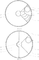
- FIG. 4 shows a cross section through the filter device according to FIG. 3 along the cross-sectional line D.
- the geometry of the cleaning chamber 20 Lateral of the cleaning chamber 20 is the air inlet opening 21 which is connected substantially at right angles to the tangent of an outer enclosure of the cleaning chamber 20. Laterally offset from the air inlet opening 21 is a collection chamber connection 23 within the cleaning chamber 20.
- the cleaning chamber 20 also has a guide surface 22, through which a flow entering through the air inlet opening 21 in the cleaning chamber 20, is deflected and forms a vortex before the Flow leaves the cleaning chamber 20 through the plenum connection 23. By the guide surface 22 can thereby desired Flow conditions are created in the cleaning chamber 20.
- the guide surface 22 extends from a lower region of the cleaning chamber 20 to an upper region of the cleaning chamber 20 and at the same time forms the partition to the dirt region 12 of the filter chamber 10 (see FIG. 3 ). In the dirt area 12 while the dirt area connection 15 is visible.
- FIG. 5 shows a cross section along the line C from the FIG. 3 , It can be seen that above the guide surface 22 (see FIG. 4 ) the partition wall 41 extends horizontally (see FIG. 3 ) and thereby forms a degree. The description of the FIG. 4 identical elements were not repeated in the present case and omitted the detailed representation of the guide surface 22.
- the partition 41 in FIG. 5 is formed of two interconnected circle segments.
- the circle segments are each slightly larger than a cell of the filter element 30 (see FIG. 6 ). It is thus possible that at least two spokes 33 between cells of the filter element 30 are always in contact with the dividing wall 41. This ensures that the cleaning chamber 20 is separated from the dirt area.
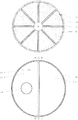
- FIG. 6 shows a filter element 30, in a plan view along the cross-section B of the FIG. 3 , namely a view of the clean surface 32 (see FIG. 2 ).
- the filter element 30 is presently designed as a cellular wheel with eight individual cells 34. Between each cell 34 there is a web 33 with a seal which communicates with the partition wall 41 (see FIG FIG. 5 ) cooperates.
- FIG. 7 shows a plan view along the section A of the filter device according to the FIG. 3 , In this view, only the suction housing 50 is visible.
- the suction housing 50 has the air outlet opening 11, which is arranged in the lid 53 of the suction housing.
- the wall 52 is likewise visible on the suction housing, which covers the filter element 30 in the area of the cleaning chamber 20 on the side of the clean area, so that no flow through the filter element 30 can occur in the area of the cleaning chamber 20 (see FIG. 3 ).
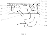
- FIG. 8 shows a lateral view, substantially perpendicular to the sectional view according to FIG. 3 , Shown in FIG. 8 are the specific flow conditions within the cleaning chamber 20.
- FIG. 8 Thus, FIG. 1 shows the cleaning chamber 20 with a collecting chamber connection 23 with a bow tube 24 adjoining it. The air inlet opening 21 is shown by dashed lines through which the fluid enters the cleaning chamber 20.
- the cleaning chamber 20 is located in the filter housing 40 (see FIG. 2 ).
- the filter housing 40 has a bottom 42.
- the cleaning chamber is how to FIG. 2 explained limited by the partition 41. This partition 41 extends above the cleaning chamber 20 and forms a sealing surface for seals, which are arranged on spokes 33 of the filter element 30.
- the fluid flow S is shown here with arrows.
- the filter element 30 is shown schematically, which filter element 30 at its upper side with the cover element 51 of the suction housing 50 (FIGS. FIG. 7 ) is covered.
- the filter element 30 rotates counterclockwise, that is, in the present illustration, from left to right.
- the filter element 30 is covered with a filter cake F.
- the fluid enters the cleaning chamber 20 through the air inlet opening 21.
- guide surface 22 see FIG. 2 and FIG. 4
- the fluid flow is deflected and flows along the filter element 30.
- the guide surface 22 are formed such that form a plurality of vortices W along the filter element 30. This favors the separation of the filter cake F from the filter element 30.
- FIG. 9 shows an alternative embodiment of a filter housing 40 of a filter device 100 (see FIG. 1 ).
- the filter housing 40 has a cleaning chamber 20, which is formed substantially in the form of a channel.
- the filter housing 40 also has a portion of a filter chamber 10 (see FIG. 1 and FIG. 3 ), namely the dirt area 12.
- the dirt area 12 of the filter chamber 10 is separated by a partition wall 41 of the cleaning chamber 20.
- a plenum connection 23 can be seen, which with a first arc tube 24 a (in FIG. 9 not shown, see FIG. 11 ) and a bow tube 24 into the collecting space 101 (FIG. FIG. 1 ) connected is.
- the first arc tube 24a is connected at the other end to the first header connection 23 (see also FIG. 11 ).
- a dip tube 14 is arranged, which the collecting space 101 (FIG. FIG. 1 ) with the dirt area 12 via a dirt area connection 15 (see FIG. 3 ) connects.
- a filter element 30 is arranged at the top of the filter housing 40.
- the filter element 30 is designed as a rotary valve (see also FIG. 6 ).
- One side of the filter element 30 (dirt surface 31) is assigned to the dirt area 12. During operation, dust, a filter cake, collects in this area forms (see also FIG. 3 ).
- the filter element 30 is rotatable on a central axis.
- the filter element 30 can be rotated in both directions, as indicated by the arrows. Preferably, however, the filter element 30 rotates counterclockwise. In this case, the filter cake, which has formed in the dirt area 12 on the dirt surface 31, is rotated in the direction of the cleaning chamber 20. By the suction force along the spokes (33) of the filter cake is dissolved within the cleaning chamber 20 of the dirt surface 31 of the filter element 30 and with the air flow into the collecting space 101 ( FIG. 1 ) carried.
- FIG. 10 shows a cross section through an alternative embodiment of the filter device according to FIG. 1 , wherein the collecting space 101 is not completely shown.
- the cross-section extends through the plane along the end of the arc tube 24 (see FIG. 9 ).
- a suction housing 50 with an air outlet opening 11 can be seen.
- the suction housing 50 in the present case has a cover 53 in which the air outlet opening 11 is arranged.
- At Absauggecher 50 is a wall 52 for receiving the axis of rotation 35 (see FIG. 9 ) arranged.
- the suction housing has a cover element 51.
- the suction housing 50 also has an outer enclosure 54.
- This housing 54 extends substantially to a level in which the dirt surface 31 is located. That is, the housing 54 extends over the filter element 30. It can be provided that the filter housing 40 has an additional, separate housing or that the filter housing, as shown here, is located within a housing of the collecting space 101. Likewise, it would be conceivable that the enclosure 54 via the filter element 30 and the filter housing 40th (please refer Figures 2 and 1 ) extends together. The filter element 30 and the filter housing 40 are separated from the environment.
- the enclosure 54 extends above the lid 53 and forms an additional space.
- the suction motor 2 FIG. 1
- other accessories may be arranged.
- the filter element 30 is located within the filter chamber 10.
- the filter chamber 10 is presently formed by the filter housing 40 and the suction 50.
- the fluid flows through the dip tube 14 into the dirt area 12 and through the filter element 30 into the clean area 13.
- a filter cake F settles on the dirt surface 31 of the filter element.
- a cleaning channel 20a which in this embodiment assumes the function of the cleaning chamber 20, in which the filter element 30 extends.
- the cleaning channel 20a is connected to the collecting container 101 by means of the first curved tube 24a and the curved tube 24, this in turn by means of the dip tube 14 via the dirt area connection 15 with the dirt area 12 of the filter chamber 10.
- the first curved tube 24a extends partially in the cleaning chamber 20 and partially in the Dirt area 12. In FIG. 10 only the part of the bow tube 24a is shown, which extends in the dirt area 12. The part of the arc tube 24a, which runs in the cleaning chamber 20 is not shown for clarity.
- a filter cake F which has formed on the dirt surface of the filter element 30, by the rotation of the filter element 30 (see FIG. 2 ) in the cleaning channel 20a brought in.
- the air flow, which forms in the cleaning channel 20a, makes it possible to separate the filter cake F from the filter element 30 and thus to clean the filter element 30 and to provide it for reuse in the filter chamber 10.
- the filter element 30 has at its spokes 33 (see FIG. 6 ) Sealing elements. These act on the one hand with the partition 41 (The partition 41 is partially right to the suction 50 executed (see FIG. 11 ), but is shown in a shortened for a better overview) and on the other hand with the cover member 51 of the suction 50 together.
- the sealing elements prevent impermissible air flows between the individual components of the device.
- the partition wall 41 has a further guide surface 18 which is associated with the dirt area 12.
- the partition wall 41 may have a different thickness over its course.
- the partition wall 41 opposite a further guide surface 16 may be provided.
- the guide surfaces in the dirt area 12 are formed such that the flow in the dirt area 12 and in the clean area 13 is as quiet as possible and vortexes are avoided.
- the air outlet opening 11 is not as in FIG. 10 shown vertically on the lid 53 of the suction 50 but attached to one of the two vertical walls 52, 54. This results in a substantially horizontally running away from the housing air outlet opening 11th
- FIG. 10 corresponds, the guide surfaces 16 of the dirt area 12 (see FIG. 10 ) the separation to the collection container 101 and not the filter housing bottom 42 (see FIG. 10 ).
- the filter device can be made simpler and thus more economical.
- FIG. 11 shows a cross section along the line D of FIG. 10 , Lateral of the cleaning channel 20a is the air inlet opening 21, which is connected substantially at right angles to the tangent of an outer enclosure of the cleaning chamber. Laterally offset from the air inlet opening 21 there is another collecting chamber connection 23a within the cleaning chamber.
- the guide surface 18, which are part of the cleaning channel 20a a flow entering through the air inlet opening 21 in the cleaning channel 20a, deflected and formed a suction and / or vortex, before the flow leaves the cleaning channel 20a through the plenum connection 23a. Through the guide surface 18 desired flow conditions can be created in the cleaning channel 20a.
- the guide surface 18 extends from a lower portion of the cleaning chamber 20 to an upper portion of the cleaning chamber 20 and at the same time the partition wall to the collecting container 101 (see FIG. 10 form.
- the first arc tube 24a connects the collection space connection 23 with the further collective connection 23a and cleaning chamber 20a.
- the first arc tube 24a and the arc tube 24 (not shown) together form a multiple arc tube. In the dirt area 12, the dirt area connection 15 is visible.
- FIG. 12 shows a cross section through the filter device according to FIG. 10 along the cross-sectional line C. Visible is the geometry of the cleaning channel 20a. The description of the FIG. 11 identical elements were not repeated here. In the dirt area 12, the dirt area connection 15 is visible. The filter housing 40 and the partition wall 41 are shown.
- FIG. 13 shows a further embodiment of the invention.
- the cover 53 and the enclosure 54 are designed in one piece as an arcuate, half-round cover 53, 54 and thus form the wall 52 and the suction housing 50.
- the air outlet opening 11 at any point of the semicircular lid 53, 54 may be arranged.
- FIG. 13 are already in FIG. 10 labeled and described parts not labeled again. The preceding description of these parts FIG. 10 also applies to FIG. 13 ,
- FIG. 14 shows a further embodiment of the invention.
- the cleaning chamber 20 is designed as a cleaning channel 20a.
- This cleaning channel 20a extends between the further plenum connection 23a and the air inlet opening 21 (not shown).
- the cleaning channel 20a is tubular in shape, which is slightly bent at both ends. The bends allow the channel at the ends to connect conclusively.
- FIG. 14 shows a first filter cake stream F1, which comes about by a left-hand rotation of the filter element 30.
- FIG. 14 shows as an alternative to the first filter cake stream F1 a second filter cake stream F2, which comes about by a clockwise rotation of the filter element 30.
- the cleaning channel 20a can also be designed as edged, in particular polygonal.
- the cleaning channel 20a is in a further embodiment (not shown) straight, that is formed without bends.
- the cleaning channel 20a has an opening in the region which faces the dirt surface 31. This opening runs along the entire dirt surface 31 facing portion of the cleaning channel 20 a. The result is a large area connection through which the filter cake F falls during operation in the cleaning channel 20a.
- the cleaning channel 20a has substantially the same cross-sectional area as a suction tube or a suction tube which belongs to the filter device.
- the cross-sectional area is chosen to be as small as possible, so that a sufficiently large air flow for cleaning the filter element 30 is formed, but large enough so that no solids remain hanging.
- FIG. 14 in the region of the cleaning chamber 20 no filter housing bottom 42 is present.
- the cleaning channel 20a opens on the further plenum connection 23a, to which also the multiple arc tube 24, 24a is connected, which opens directly into the collecting container 101.
- FIG. 15 shows a further embodiment of the invention, which comprises a stripper brush 36 in the cleaning chamber 20.
- the stripping brush 36 is arranged so that it participates in the cleaning of the filter cake F.
- clogging of the filter element is further complicated. This is particularly advantageous in applications with slightly adhesive suction material, for example flakes in water damage, fresh wood sawdust, high moisture content or even with suction, which easily adheres due to electrostatic charge, advantageous.
- FIG. 15 are already in FIG. 10 labeled and parts not labeled again. The preceding description of these parts FIG. 10 also applies to FIG. 15 ,
- FIG. 16 shows a further embodiment of the invention, in which in the cleaning channel 20a, a protective device 37 is mounted to protect the filter element 30.
- the protective device 37 is designed in the form of lamellae in this embodiment.
- the fins are arranged at an angle to the filter element 30. This allows the protective device 37 to perform its function as protection of the filter element 30 against solids possibly present in the air flowing in through the air inlet opening 21, without rendering the cleaning of the filter cake F from the filter element 30 impossible.
- the protective device 37 is mounted exclusively in the air inlet region (in the vicinity of the air inlet opening 21) of the cleaning channel 20a. There are two slats, which run parallel to each other. In FIG. 16 are already in FIG.
- FIG. 10 labeled and described parts not labeled again.
- the preceding description of these parts FIG. 10 also applies to FIG. 16 .
- further embodiments are in addition to the cut in FIG. 16 slats shown, more slats present, for example, so that in section in FIG. 16 one, two or three further slats are attached.
- the lamellae extend over essentially the entire surface of the filter element 30 in the cleaning channel 20a, which is not covered by the dividing wall 41. The filter element 30 is thus protected on the entire exposed surface by the protection device 37.
Landscapes
- Engineering & Computer Science (AREA)
- Mechanical Engineering (AREA)
- Filtering Of Dispersed Particles In Gases (AREA)
Claims (14)
- Dispositif filtrant (100) pour filtrer un fluide, en particulier un courant d'air, comprenant une chambre collectrice (101), une chambre filtrante (10), une chambre de nettoyage (20) et un élément filtrant (30), la chambre de nettoyage (20) présentant une ouverture d'entrée d'air (21) et la chambre de filtrage (10) présentant une ouverture de sortie d'air (11), dans laquelle la chambre de nettoyage (20) et la chambre de filtrage (10) sont en communication fluidique au moyen de la chambre collectrice (101), la chambre de nettoyage (20), la chambre collectrice(101) et la chambre de filtrage (10) étant disposées l'une après l'autre dans une direction de flux, l'élément filtrant (30) en étant disposé de la façon dans la chambre de filtrage (10), en ce que la chambre de filtrage (10) est subdivisée en une zone de saleté (12) et une zone propre (13), l'élément filtrant (30) présentant une surface de saleté (31) tournée vers la zone de saleté (12) et une surface propre (32) tournée vers la zone propre (13), caractérisée en ce que l'élément filtrant (30) s'étend au moins partiellement dans la chambre de nettoyage (20) de telle sorte que le fluide est guidé au moins partiellement le long de la surface de saleté (31) et s'écoule en particulier le long de celle-ci de telle sorte qu'un gâteau de filtre (F) situé sur l'élément filtrant (30) puisse être séparé de la surface de saleté (31).
- Dispositif de filtration selon la revendication 1, caractérisé en ce que la zone de saleté (12) est formée comme une chambre à poussière (121).
- Dispositif de filtration selon la revendication 1 ou 2, caractérisé en ce que la zone propre (13) est conçue comme une chambre à l'air (122).
- Dispositif filtrant selon l'une des revendications 1 à 3, caractérisé en ce que l'élément filtrant (30) est conçu pour pouvoir tourner autour d'un axe de rotation (35).
- Dispositif filtrant selon l'une des revendications 1 à 4, caractérisé en ce que l'élément filtrant (30) est conçu comme une roue cellulaire.
- Dispositif de filtration selon l'une des revendications 1 à 5, caractérisé en ce que la zone d'encrassement (12) de la chambre de filtration (10) et la chambre de nettoyage (20) sont formées dans un boîtier de filtration commun (40).
- Dispositif de filtration selon l'une des revendications 1 à 6, caractérisé en ce que la zone propre (13) de la chambre de filtration (10) est formée dans un boîtier d'aspiration séparé (50).
- Dispositif de filtration selon l'une des revendications 1 à 7, caractérisé en ce que la communication fluidique entre la chambre de nettoyage (20) et le récipient collecteur (101) est conçue comme un tube coudé (103) de telle manière qu'un cyclone se forme dans le récipient collecteur (101).
- Dispositif de filtration selon l'une des revendications 1 à 8, caractérisé en ce que la communication fluidique entre le récipient collecteur (101) et la chambre de filtration est réalisée sous la forme d'un tuyau droit (104) qui est disposé de préférence au centre du récipient collecteur (101) de telle sorte que le fluide puisse être aspiré au centre d'un cyclone formé dans le récipient collecteur (101) .
- Dispositif filtrant selon l'une des revendications 1 à 9, caractérisé en ce qu'une surface de guidage (22) est disposée dans la chambre de nettoyage (20) de telle sorte qu'un écoulement du fluide entrant dans la chambre de nettoyage (20) par le raccord d'aspiration (21) est dévié de telle manière qu'au moins un tourbillon se forme dans l'écoulement du fluide, au moins une partie de l'écoulement dans le tourbillon étant orientée le long de l'élément filtrant (30).
- Dispositif filtrant selon l'une des revendications 1 à 10, caractérisé en ce qu'une paroi de séparation (41) est formée pour empêcher l'écoulement entre la chambre de nettoyage (20) et la chambre de filtration (10).
- Procédé pour filtrer un fluide, en particulier un courant d'air, en particulier avec un dispositif selon l'une des revendications 1 à 11, dans lequel le fluide est guidé successivement à travers une chambre de nettoyage (20), une chambre collectrice (101) et une chambre de filtrage (10) et le fluide est guidé dans la chambre de filtrage (10) par un élément filtrant (30), l'élément filtrant étant disposé dans la chambre de filtrage (10) de telle manière que la chambre de filtrage (10) soit divisée en une région de saleté (12) et dans une région propre (13) disposée successivement dans une direction de flux , l'élément filtrant (30) présentant une surface de saleté (31) tournée vers la zone de saleté (12) et une surface propre (32) tournée vers la zone propre (12), caractérisé en ce que l'élément filtrant (30) s'étend dans la chambre de nettoyage (20) et en ce que le fluide est guidé au moins partiellement sur la surface de saleté (31) et passe en particulier à travers celle-ci de telle sorte que, sur l'élément filtrant (30), il se dégage une couche de filtration (F) qui se trouve sur la surface de saleté (31).
- Procédé selon la revendication 12, caractérisé en ce que l'élément filtrant (30) est mis en rotation pendant le fonctionnement dans la chambre de nettoyage (20) ou à l'opposé de la direction d'écoulement du fluide, la rotation étant intermittente ou continue, l'élément filtrant étant de préférence entraîné par le flux d'air ou par une source externe.
- Aspirateur comprenant un dispositif selon l'une des revendications 1 à 11, en particulier pour effectuer une procédure selon l'une des revendications 12 à 13.
Applications Claiming Priority (1)
| Application Number | Priority Date | Filing Date | Title |
|---|---|---|---|
| EP16201873.3A EP3329822A1 (fr) | 2016-12-02 | 2016-12-02 | Dispositif de filtre pour la filtration d'un fluide, procédé de filtration d'un fluide et aspirateur |
Publications (2)
| Publication Number | Publication Date |
|---|---|
| EP3329824A1 EP3329824A1 (fr) | 2018-06-06 |
| EP3329824B1 true EP3329824B1 (fr) | 2019-07-31 |
Family
ID=57471719
Family Applications (2)
| Application Number | Title | Priority Date | Filing Date |
|---|---|---|---|
| EP16201873.3A Withdrawn EP3329822A1 (fr) | 2016-12-02 | 2016-12-02 | Dispositif de filtre pour la filtration d'un fluide, procédé de filtration d'un fluide et aspirateur |
| EP17201239.5A Active EP3329824B1 (fr) | 2016-12-02 | 2017-11-13 | Dispositif de filtration destiné à la filtration d'un fluide, procédé de filtration d'un fluide et aspirateur |
Family Applications Before (1)
| Application Number | Title | Priority Date | Filing Date |
|---|---|---|---|
| EP16201873.3A Withdrawn EP3329822A1 (fr) | 2016-12-02 | 2016-12-02 | Dispositif de filtre pour la filtration d'un fluide, procédé de filtration d'un fluide et aspirateur |
Country Status (1)
| Country | Link |
|---|---|
| EP (2) | EP3329822A1 (fr) |
Family Cites Families (4)
| Publication number | Priority date | Publication date | Assignee | Title |
|---|---|---|---|---|
| US6195835B1 (en) * | 1998-12-02 | 2001-03-06 | Samsung Kwangju Electronics Co., Ltd. | Vacuum cleaner having a cyclone dust collecting device |
| KR100433414B1 (ko) | 2002-05-11 | 2004-05-31 | 삼성광주전자 주식회사 | 진공청소기용 사이클론 집진장치 |
| US7717973B2 (en) * | 2007-09-05 | 2010-05-18 | Samsung Gwangju Elecetronics Co., Ltd. | Cyclone dust-separating apparatus of vacuum cleaner |
| US7981181B2 (en) * | 2008-01-16 | 2011-07-19 | Samsung Gwangju Electronics Co., Ltd. | Cyclone dust-separating apparatus and cleaner having the same |
-
2016
- 2016-12-02 EP EP16201873.3A patent/EP3329822A1/fr not_active Withdrawn
-
2017
- 2017-11-13 EP EP17201239.5A patent/EP3329824B1/fr active Active
Non-Patent Citations (1)
| Title |
|---|
| None * |
Also Published As
| Publication number | Publication date |
|---|---|
| EP3329824A1 (fr) | 2018-06-06 |
| EP3329822A1 (fr) | 2018-06-06 |
Similar Documents
| Publication | Publication Date | Title |
|---|---|---|
| EP2002773B1 (fr) | Aspirateur | |
| DE102014017483A1 (de) | Filtergehäuse und Filteranordnung | |
| EP1262223A1 (fr) | Separateur a inertie | |
| EP1500423A1 (fr) | Assemblage de filtre du type vortex | |
| EP3117904A1 (fr) | Dispositif de separation pour de petites parties d'un flux de fluide | |
| EP3298241A1 (fr) | Pompe à vide à palettes lubrifiée à l'huile munie d'un dispositif de séparation et de recyclage de l'huile | |
| EP3482078A1 (fr) | Pompe à vide à tiroir rotatif lubrifiée à l'huile | |
| DE102004056856A1 (de) | Grobabscheider | |
| DE2628586A1 (de) | Verfahren zum filtrieren von in einem gasstrom mitgefuehrten partikeln und vorrichtung zur durchfuehrung dieses verfahrens | |
| EP1965889B1 (fr) | Systeme d'epuration de gaz | |
| DE102017011876A1 (de) | Luftfilter mit integriertem Schneeschutz und Filterelement | |
| EP1364696B1 (fr) | Dispositif d'épuration d'un courant gazeux | |
| EP3329824B1 (fr) | Dispositif de filtration destiné à la filtration d'un fluide, procédé de filtration d'un fluide et aspirateur | |
| AT522780B1 (de) | Vorrichtung zur reinigung von gas | |
| WO2000018490A1 (fr) | Procede et dispositif pour enlever des particules contenues dans un fluide | |
| DE19528286C2 (de) | Abscheider für mit Feststoff- oder Flüssigpartikeln beladene Gasströme | |
| WO2000026141A1 (fr) | Installation compacte pour l'epuration mecanique d'eaux usees | |
| EP2827968B1 (fr) | Elément de filtre doté d'une unité de nettoyage pour grands débits volumiques | |
| DE102016121779B4 (de) | Filteranlage mit Reinigungsluftleiteinrichtung für horizontale Filterpatronen | |
| DE4033223A1 (de) | Vorrichtung zur reinigung von wasser | |
| DE10126048A1 (de) | Vorrichtung zum Reinigen staubbeladener Rohgase | |
| WO1996006046A1 (fr) | Installation d'epuration d'eaux usees | |
| EP3920765A1 (fr) | Dispositif d'évacuation par aspiration de poussières et procédé de changement d'un élément filtrant dans un dispositif d'évacuation par aspiration de poussières | |
| DE2533384C2 (de) | Luftreiniger | |
| DE29518534U1 (de) | Filter zum kontinuierlichen Filtern von Feststoffe aufweisenden Flüssigkeiten |
Legal Events
| Date | Code | Title | Description |
|---|---|---|---|
| PUAI | Public reference made under article 153(3) epc to a published international application that has entered the european phase |
Free format text: ORIGINAL CODE: 0009012 |
|
| STAA | Information on the status of an ep patent application or granted ep patent |
Free format text: STATUS: THE APPLICATION HAS BEEN PUBLISHED |
|
| AK | Designated contracting states |
Kind code of ref document: A1 Designated state(s): AL AT BE BG CH CY CZ DE DK EE ES FI FR GB GR HR HU IE IS IT LI LT LU LV MC MK MT NL NO PL PT RO RS SE SI SK SM TR |
|
| AX | Request for extension of the european patent |
Extension state: BA ME |
|
| STAA | Information on the status of an ep patent application or granted ep patent |
Free format text: STATUS: REQUEST FOR EXAMINATION WAS MADE |
|
| 17P | Request for examination filed |
Effective date: 20181128 |
|
| RBV | Designated contracting states (corrected) |
Designated state(s): AL AT BE BG CH CY CZ DE DK EE ES FI FR GB GR HR HU IE IS IT LI LT LU LV MC MK MT NL NO PL PT RO RS SE SI SK SM TR |
|
| GRAP | Despatch of communication of intention to grant a patent |
Free format text: ORIGINAL CODE: EPIDOSNIGR1 |
|
| STAA | Information on the status of an ep patent application or granted ep patent |
Free format text: STATUS: GRANT OF PATENT IS INTENDED |
|
| INTG | Intention to grant announced |
Effective date: 20190304 |
|
| GRAS | Grant fee paid |
Free format text: ORIGINAL CODE: EPIDOSNIGR3 |
|
| GRAA | (expected) grant |
Free format text: ORIGINAL CODE: 0009210 |
|
| STAA | Information on the status of an ep patent application or granted ep patent |
Free format text: STATUS: THE PATENT HAS BEEN GRANTED |
|
| AK | Designated contracting states |
Kind code of ref document: B1 Designated state(s): AL AT BE BG CH CY CZ DE DK EE ES FI FR GB GR HR HU IE IS IT LI LT LU LV MC MK MT NL NO PL PT RO RS SE SI SK SM TR |
|
| REG | Reference to a national code |
Ref country code: CH Ref legal event code: EP Ref country code: GB Ref legal event code: FG4D Free format text: NOT ENGLISH |
|
| REG | Reference to a national code |
Ref country code: AT Ref legal event code: REF Ref document number: 1160022 Country of ref document: AT Kind code of ref document: T Effective date: 20190815 |
|
| REG | Reference to a national code |
Ref country code: IE Ref legal event code: FG4D Free format text: LANGUAGE OF EP DOCUMENT: GERMAN |
|
| REG | Reference to a national code |
Ref country code: DE Ref legal event code: R096 Ref document number: 502017001893 Country of ref document: DE |
|
| REG | Reference to a national code |
Ref country code: CH Ref legal event code: NV Representative=s name: HEPP WENGER RYFFEL AG, CH |
|
| REG | Reference to a national code |
Ref country code: NL Ref legal event code: MP Effective date: 20190731 |
|
| REG | Reference to a national code |
Ref country code: LT Ref legal event code: MG4D |
|
| PG25 | Lapsed in a contracting state [announced via postgrant information from national office to epo] |
Ref country code: LT Free format text: LAPSE BECAUSE OF FAILURE TO SUBMIT A TRANSLATION OF THE DESCRIPTION OR TO PAY THE FEE WITHIN THE PRESCRIBED TIME-LIMIT Effective date: 20190731 Ref country code: PT Free format text: LAPSE BECAUSE OF FAILURE TO SUBMIT A TRANSLATION OF THE DESCRIPTION OR TO PAY THE FEE WITHIN THE PRESCRIBED TIME-LIMIT Effective date: 20191202 Ref country code: BG Free format text: LAPSE BECAUSE OF FAILURE TO SUBMIT A TRANSLATION OF THE DESCRIPTION OR TO PAY THE FEE WITHIN THE PRESCRIBED TIME-LIMIT Effective date: 20191031 Ref country code: NL Free format text: LAPSE BECAUSE OF FAILURE TO SUBMIT A TRANSLATION OF THE DESCRIPTION OR TO PAY THE FEE WITHIN THE PRESCRIBED TIME-LIMIT Effective date: 20190731 Ref country code: NO Free format text: LAPSE BECAUSE OF FAILURE TO SUBMIT A TRANSLATION OF THE DESCRIPTION OR TO PAY THE FEE WITHIN THE PRESCRIBED TIME-LIMIT Effective date: 20191031 Ref country code: HR Free format text: LAPSE BECAUSE OF FAILURE TO SUBMIT A TRANSLATION OF THE DESCRIPTION OR TO PAY THE FEE WITHIN THE PRESCRIBED TIME-LIMIT Effective date: 20190731 Ref country code: FI Free format text: LAPSE BECAUSE OF FAILURE TO SUBMIT A TRANSLATION OF THE DESCRIPTION OR TO PAY THE FEE WITHIN THE PRESCRIBED TIME-LIMIT Effective date: 20190731 Ref country code: SE Free format text: LAPSE BECAUSE OF FAILURE TO SUBMIT A TRANSLATION OF THE DESCRIPTION OR TO PAY THE FEE WITHIN THE PRESCRIBED TIME-LIMIT Effective date: 20190731 |
|
| PG25 | Lapsed in a contracting state [announced via postgrant information from national office to epo] |
Ref country code: IS Free format text: LAPSE BECAUSE OF FAILURE TO SUBMIT A TRANSLATION OF THE DESCRIPTION OR TO PAY THE FEE WITHIN THE PRESCRIBED TIME-LIMIT Effective date: 20191130 Ref country code: LV Free format text: LAPSE BECAUSE OF FAILURE TO SUBMIT A TRANSLATION OF THE DESCRIPTION OR TO PAY THE FEE WITHIN THE PRESCRIBED TIME-LIMIT Effective date: 20190731 Ref country code: RS Free format text: LAPSE BECAUSE OF FAILURE TO SUBMIT A TRANSLATION OF THE DESCRIPTION OR TO PAY THE FEE WITHIN THE PRESCRIBED TIME-LIMIT Effective date: 20190731 Ref country code: ES Free format text: LAPSE BECAUSE OF FAILURE TO SUBMIT A TRANSLATION OF THE DESCRIPTION OR TO PAY THE FEE WITHIN THE PRESCRIBED TIME-LIMIT Effective date: 20190731 Ref country code: GR Free format text: LAPSE BECAUSE OF FAILURE TO SUBMIT A TRANSLATION OF THE DESCRIPTION OR TO PAY THE FEE WITHIN THE PRESCRIBED TIME-LIMIT Effective date: 20191101 Ref country code: AL Free format text: LAPSE BECAUSE OF FAILURE TO SUBMIT A TRANSLATION OF THE DESCRIPTION OR TO PAY THE FEE WITHIN THE PRESCRIBED TIME-LIMIT Effective date: 20190731 |
|
| PG25 | Lapsed in a contracting state [announced via postgrant information from national office to epo] |
Ref country code: TR Free format text: LAPSE BECAUSE OF FAILURE TO SUBMIT A TRANSLATION OF THE DESCRIPTION OR TO PAY THE FEE WITHIN THE PRESCRIBED TIME-LIMIT Effective date: 20190731 |
|
| PG25 | Lapsed in a contracting state [announced via postgrant information from national office to epo] |
Ref country code: RO Free format text: LAPSE BECAUSE OF FAILURE TO SUBMIT A TRANSLATION OF THE DESCRIPTION OR TO PAY THE FEE WITHIN THE PRESCRIBED TIME-LIMIT Effective date: 20190731 Ref country code: EE Free format text: LAPSE BECAUSE OF FAILURE TO SUBMIT A TRANSLATION OF THE DESCRIPTION OR TO PAY THE FEE WITHIN THE PRESCRIBED TIME-LIMIT Effective date: 20190731 Ref country code: IT Free format text: LAPSE BECAUSE OF FAILURE TO SUBMIT A TRANSLATION OF THE DESCRIPTION OR TO PAY THE FEE WITHIN THE PRESCRIBED TIME-LIMIT Effective date: 20190731 Ref country code: DK Free format text: LAPSE BECAUSE OF FAILURE TO SUBMIT A TRANSLATION OF THE DESCRIPTION OR TO PAY THE FEE WITHIN THE PRESCRIBED TIME-LIMIT Effective date: 20190731 Ref country code: PL Free format text: LAPSE BECAUSE OF FAILURE TO SUBMIT A TRANSLATION OF THE DESCRIPTION OR TO PAY THE FEE WITHIN THE PRESCRIBED TIME-LIMIT Effective date: 20190731 |
|
| PG25 | Lapsed in a contracting state [announced via postgrant information from national office to epo] |
Ref country code: CZ Free format text: LAPSE BECAUSE OF FAILURE TO SUBMIT A TRANSLATION OF THE DESCRIPTION OR TO PAY THE FEE WITHIN THE PRESCRIBED TIME-LIMIT Effective date: 20190731 Ref country code: SK Free format text: LAPSE BECAUSE OF FAILURE TO SUBMIT A TRANSLATION OF THE DESCRIPTION OR TO PAY THE FEE WITHIN THE PRESCRIBED TIME-LIMIT Effective date: 20190731 Ref country code: IS Free format text: LAPSE BECAUSE OF FAILURE TO SUBMIT A TRANSLATION OF THE DESCRIPTION OR TO PAY THE FEE WITHIN THE PRESCRIBED TIME-LIMIT Effective date: 20200224 Ref country code: SM Free format text: LAPSE BECAUSE OF FAILURE TO SUBMIT A TRANSLATION OF THE DESCRIPTION OR TO PAY THE FEE WITHIN THE PRESCRIBED TIME-LIMIT Effective date: 20190731 |
|
| REG | Reference to a national code |
Ref country code: DE Ref legal event code: R097 Ref document number: 502017001893 Country of ref document: DE |
|
| PLBE | No opposition filed within time limit |
Free format text: ORIGINAL CODE: 0009261 |
|
| STAA | Information on the status of an ep patent application or granted ep patent |
Free format text: STATUS: NO OPPOSITION FILED WITHIN TIME LIMIT |
|
| PG2D | Information on lapse in contracting state deleted |
Ref country code: IS |
|
| PG25 | Lapsed in a contracting state [announced via postgrant information from national office to epo] |
Ref country code: MC Free format text: LAPSE BECAUSE OF FAILURE TO SUBMIT A TRANSLATION OF THE DESCRIPTION OR TO PAY THE FEE WITHIN THE PRESCRIBED TIME-LIMIT Effective date: 20190731 Ref country code: LU Free format text: LAPSE BECAUSE OF NON-PAYMENT OF DUE FEES Effective date: 20191113 Ref country code: IS Free format text: LAPSE BECAUSE OF FAILURE TO SUBMIT A TRANSLATION OF THE DESCRIPTION OR TO PAY THE FEE WITHIN THE PRESCRIBED TIME-LIMIT Effective date: 20191030 |
|
| 26N | No opposition filed |
Effective date: 20200603 |
|
| REG | Reference to a national code |
Ref country code: BE Ref legal event code: MM Effective date: 20191130 |
|
| PG25 | Lapsed in a contracting state [announced via postgrant information from national office to epo] |
Ref country code: SI Free format text: LAPSE BECAUSE OF FAILURE TO SUBMIT A TRANSLATION OF THE DESCRIPTION OR TO PAY THE FEE WITHIN THE PRESCRIBED TIME-LIMIT Effective date: 20190731 |
|
| PG25 | Lapsed in a contracting state [announced via postgrant information from national office to epo] |
Ref country code: FR Free format text: LAPSE BECAUSE OF NON-PAYMENT OF DUE FEES Effective date: 20191130 Ref country code: IE Free format text: LAPSE BECAUSE OF NON-PAYMENT OF DUE FEES Effective date: 20191113 |
|
| PG25 | Lapsed in a contracting state [announced via postgrant information from national office to epo] |
Ref country code: BE Free format text: LAPSE BECAUSE OF NON-PAYMENT OF DUE FEES Effective date: 20191130 |
|
| PG25 | Lapsed in a contracting state [announced via postgrant information from national office to epo] |
Ref country code: CY Free format text: LAPSE BECAUSE OF FAILURE TO SUBMIT A TRANSLATION OF THE DESCRIPTION OR TO PAY THE FEE WITHIN THE PRESCRIBED TIME-LIMIT Effective date: 20190731 |
|
| PG25 | Lapsed in a contracting state [announced via postgrant information from national office to epo] |
Ref country code: HU Free format text: LAPSE BECAUSE OF FAILURE TO SUBMIT A TRANSLATION OF THE DESCRIPTION OR TO PAY THE FEE WITHIN THE PRESCRIBED TIME-LIMIT; INVALID AB INITIO Effective date: 20171113 Ref country code: MT Free format text: LAPSE BECAUSE OF FAILURE TO SUBMIT A TRANSLATION OF THE DESCRIPTION OR TO PAY THE FEE WITHIN THE PRESCRIBED TIME-LIMIT Effective date: 20190731 |
|
| PG25 | Lapsed in a contracting state [announced via postgrant information from national office to epo] |
Ref country code: MK Free format text: LAPSE BECAUSE OF FAILURE TO SUBMIT A TRANSLATION OF THE DESCRIPTION OR TO PAY THE FEE WITHIN THE PRESCRIBED TIME-LIMIT Effective date: 20190731 |
|
| GBPC | Gb: european patent ceased through non-payment of renewal fee |
Effective date: 20211113 |
|
| PG25 | Lapsed in a contracting state [announced via postgrant information from national office to epo] |
Ref country code: GB Free format text: LAPSE BECAUSE OF NON-PAYMENT OF DUE FEES Effective date: 20211113 |
|
| PGFP | Annual fee paid to national office [announced via postgrant information from national office to epo] |
Ref country code: DE Payment date: 20241029 Year of fee payment: 8 |
|
| PGFP | Annual fee paid to national office [announced via postgrant information from national office to epo] |
Ref country code: AT Payment date: 20241025 Year of fee payment: 8 |
|
| PGFP | Annual fee paid to national office [announced via postgrant information from national office to epo] |
Ref country code: CH Payment date: 20250205 Year of fee payment: 8 |