EP3330186A1 - Système et procédé de commande - Google Patents
Système et procédé de commande Download PDFInfo
- Publication number
- EP3330186A1 EP3330186A1 EP17204886.0A EP17204886A EP3330186A1 EP 3330186 A1 EP3330186 A1 EP 3330186A1 EP 17204886 A EP17204886 A EP 17204886A EP 3330186 A1 EP3330186 A1 EP 3330186A1
- Authority
- EP
- European Patent Office
- Prior art keywords
- engine
- coating
- controllers
- control system
- restoration
- Prior art date
- Legal status (The legal status is an assumption and is not a legal conclusion. Google has not performed a legal analysis and makes no representation as to the accuracy of the status listed.)
- Granted
Links
Images


Classifications
-
- B—PERFORMING OPERATIONS; TRANSPORTING
- B64—AIRCRAFT; AVIATION; COSMONAUTICS
- B64F—GROUND OR AIRCRAFT-CARRIER-DECK INSTALLATIONS SPECIALLY ADAPTED FOR USE IN CONNECTION WITH AIRCRAFT; DESIGNING, MANUFACTURING, ASSEMBLING, CLEANING, MAINTAINING OR REPAIRING AIRCRAFT, NOT OTHERWISE PROVIDED FOR; HANDLING, TRANSPORTING, TESTING OR INSPECTING AIRCRAFT COMPONENTS, NOT OTHERWISE PROVIDED FOR
- B64F5/00—Designing, manufacturing, assembling, cleaning, maintaining or repairing aircraft, not otherwise provided for; Handling, transporting, testing or inspecting aircraft components, not otherwise provided for
- B64F5/60—Testing or inspecting aircraft components or systems
-
- B—PERFORMING OPERATIONS; TRANSPORTING
- B64—AIRCRAFT; AVIATION; COSMONAUTICS
- B64D—EQUIPMENT FOR FITTING IN OR TO AIRCRAFT; FLIGHT SUITS; PARACHUTES; ARRANGEMENT OR MOUNTING OF POWER PLANTS OR PROPULSION TRANSMISSIONS IN AIRCRAFT
- B64D27/00—Arrangement or mounting of power plants in aircraft; Aircraft characterised by the type or position of power plants
- B64D27/02—Aircraft characterised by the type or position of power plants
- B64D27/10—Aircraft characterised by the type or position of power plants of gas-turbine type
-
- B—PERFORMING OPERATIONS; TRANSPORTING
- B64—AIRCRAFT; AVIATION; COSMONAUTICS
- B64D—EQUIPMENT FOR FITTING IN OR TO AIRCRAFT; FLIGHT SUITS; PARACHUTES; ARRANGEMENT OR MOUNTING OF POWER PLANTS OR PROPULSION TRANSMISSIONS IN AIRCRAFT
- B64D45/00—Aircraft indicators or protectors not otherwise provided for
-
- B—PERFORMING OPERATIONS; TRANSPORTING
- B64—AIRCRAFT; AVIATION; COSMONAUTICS
- B64F—GROUND OR AIRCRAFT-CARRIER-DECK INSTALLATIONS SPECIALLY ADAPTED FOR USE IN CONNECTION WITH AIRCRAFT; DESIGNING, MANUFACTURING, ASSEMBLING, CLEANING, MAINTAINING OR REPAIRING AIRCRAFT, NOT OTHERWISE PROVIDED FOR; HANDLING, TRANSPORTING, TESTING OR INSPECTING AIRCRAFT COMPONENTS, NOT OTHERWISE PROVIDED FOR
- B64F5/00—Designing, manufacturing, assembling, cleaning, maintaining or repairing aircraft, not otherwise provided for; Handling, transporting, testing or inspecting aircraft components, not otherwise provided for
- B64F5/40—Maintaining or repairing aircraft
-
- F—MECHANICAL ENGINEERING; LIGHTING; HEATING; WEAPONS; BLASTING
- F01—MACHINES OR ENGINES IN GENERAL; ENGINE PLANTS IN GENERAL; STEAM ENGINES
- F01D—NON-POSITIVE DISPLACEMENT MACHINES OR ENGINES, e.g. STEAM TURBINES
- F01D21/00—Shutting-down of machines or engines, e.g. in emergency; Regulating, controlling, or safety means not otherwise provided for
- F01D21/003—Arrangements for testing or measuring
-
- F—MECHANICAL ENGINEERING; LIGHTING; HEATING; WEAPONS; BLASTING
- F01—MACHINES OR ENGINES IN GENERAL; ENGINE PLANTS IN GENERAL; STEAM ENGINES
- F01D—NON-POSITIVE DISPLACEMENT MACHINES OR ENGINES, e.g. STEAM TURBINES
- F01D5/00—Blades; Blade-carrying members; Heating, heat-insulating, cooling or antivibration means on the blades or the members
- F01D5/12—Blades
- F01D5/28—Selecting particular materials; Particular measures relating thereto; Measures against erosion or corrosion
- F01D5/288—Protective coatings for blades
-
- F—MECHANICAL ENGINEERING; LIGHTING; HEATING; WEAPONS; BLASTING
- F02—COMBUSTION ENGINES; HOT-GAS OR COMBUSTION-PRODUCT ENGINE PLANTS
- F02C—GAS-TURBINE PLANTS; AIR INTAKES FOR JET-PROPULSION PLANTS; CONTROLLING FUEL SUPPLY IN AIR-BREATHING JET-PROPULSION PLANTS
- F02C3/00—Gas-turbine plants characterised by the use of combustion products as the working fluid
- F02C3/04—Gas-turbine plants characterised by the use of combustion products as the working fluid having a turbine driving a compressor
-
- G—PHYSICS
- G05—CONTROLLING; REGULATING
- G05B—CONTROL OR REGULATING SYSTEMS IN GENERAL; FUNCTIONAL ELEMENTS OF SUCH SYSTEMS; MONITORING OR TESTING ARRANGEMENTS FOR SUCH SYSTEMS OR ELEMENTS
- G05B23/00—Testing or monitoring of control systems or parts thereof
- G05B23/02—Electric testing or monitoring
- G05B23/0205—Electric testing or monitoring by means of a monitoring system capable of detecting and responding to faults
- G05B23/0259—Electric testing or monitoring by means of a monitoring system capable of detecting and responding to faults characterized by the response to fault detection
- G05B23/0283—Predictive maintenance, e.g. involving the monitoring of a system and, based on the monitoring results, taking decisions on the maintenance schedule of the monitored system; Estimating remaining useful life [RUL]
-
- B—PERFORMING OPERATIONS; TRANSPORTING
- B64—AIRCRAFT; AVIATION; COSMONAUTICS
- B64D—EQUIPMENT FOR FITTING IN OR TO AIRCRAFT; FLIGHT SUITS; PARACHUTES; ARRANGEMENT OR MOUNTING OF POWER PLANTS OR PROPULSION TRANSMISSIONS IN AIRCRAFT
- B64D45/00—Aircraft indicators or protectors not otherwise provided for
- B64D2045/0085—Devices for aircraft health monitoring, e.g. monitoring flutter or vibration
-
- F—MECHANICAL ENGINEERING; LIGHTING; HEATING; WEAPONS; BLASTING
- F05—INDEXING SCHEMES RELATING TO ENGINES OR PUMPS IN VARIOUS SUBCLASSES OF CLASSES F01-F04
- F05D—INDEXING SCHEME FOR ASPECTS RELATING TO NON-POSITIVE-DISPLACEMENT MACHINES OR ENGINES, GAS-TURBINES OR JET-PROPULSION PLANTS
- F05D2220/00—Application
- F05D2220/30—Application in turbines
- F05D2220/32—Application in turbines in gas turbines
- F05D2220/323—Application in turbines in gas turbines for aircraft propulsion, e.g. jet engines
-
- F—MECHANICAL ENGINEERING; LIGHTING; HEATING; WEAPONS; BLASTING
- F05—INDEXING SCHEMES RELATING TO ENGINES OR PUMPS IN VARIOUS SUBCLASSES OF CLASSES F01-F04
- F05D—INDEXING SCHEME FOR ASPECTS RELATING TO NON-POSITIVE-DISPLACEMENT MACHINES OR ENGINES, GAS-TURBINES OR JET-PROPULSION PLANTS
- F05D2230/00—Manufacture
- F05D2230/72—Maintenance
-
- F—MECHANICAL ENGINEERING; LIGHTING; HEATING; WEAPONS; BLASTING
- F05—INDEXING SCHEMES RELATING TO ENGINES OR PUMPS IN VARIOUS SUBCLASSES OF CLASSES F01-F04
- F05D—INDEXING SCHEME FOR ASPECTS RELATING TO NON-POSITIVE-DISPLACEMENT MACHINES OR ENGINES, GAS-TURBINES OR JET-PROPULSION PLANTS
- F05D2230/00—Manufacture
- F05D2230/90—Coating; Surface treatment
-
- F—MECHANICAL ENGINEERING; LIGHTING; HEATING; WEAPONS; BLASTING
- F05—INDEXING SCHEMES RELATING TO ENGINES OR PUMPS IN VARIOUS SUBCLASSES OF CLASSES F01-F04
- F05D—INDEXING SCHEME FOR ASPECTS RELATING TO NON-POSITIVE-DISPLACEMENT MACHINES OR ENGINES, GAS-TURBINES OR JET-PROPULSION PLANTS
- F05D2240/00—Components
- F05D2240/35—Combustors or associated equipment
-
- F—MECHANICAL ENGINEERING; LIGHTING; HEATING; WEAPONS; BLASTING
- F05—INDEXING SCHEMES RELATING TO ENGINES OR PUMPS IN VARIOUS SUBCLASSES OF CLASSES F01-F04
- F05D—INDEXING SCHEME FOR ASPECTS RELATING TO NON-POSITIVE-DISPLACEMENT MACHINES OR ENGINES, GAS-TURBINES OR JET-PROPULSION PLANTS
- F05D2260/00—Function
- F05D2260/80—Diagnostics
-
- F—MECHANICAL ENGINEERING; LIGHTING; HEATING; WEAPONS; BLASTING
- F05—INDEXING SCHEMES RELATING TO ENGINES OR PUMPS IN VARIOUS SUBCLASSES OF CLASSES F01-F04
- F05D—INDEXING SCHEME FOR ASPECTS RELATING TO NON-POSITIVE-DISPLACEMENT MACHINES OR ENGINES, GAS-TURBINES OR JET-PROPULSION PLANTS
- F05D2260/00—Function
- F05D2260/82—Forecasts
-
- F—MECHANICAL ENGINEERING; LIGHTING; HEATING; WEAPONS; BLASTING
- F05—INDEXING SCHEMES RELATING TO ENGINES OR PUMPS IN VARIOUS SUBCLASSES OF CLASSES F01-F04
- F05D—INDEXING SCHEME FOR ASPECTS RELATING TO NON-POSITIVE-DISPLACEMENT MACHINES OR ENGINES, GAS-TURBINES OR JET-PROPULSION PLANTS
- F05D2270/00—Control
- F05D2270/01—Purpose of the control system
- F05D2270/11—Purpose of the control system to prolong engine life
-
- F—MECHANICAL ENGINEERING; LIGHTING; HEATING; WEAPONS; BLASTING
- F05—INDEXING SCHEMES RELATING TO ENGINES OR PUMPS IN VARIOUS SUBCLASSES OF CLASSES F01-F04
- F05D—INDEXING SCHEME FOR ASPECTS RELATING TO NON-POSITIVE-DISPLACEMENT MACHINES OR ENGINES, GAS-TURBINES OR JET-PROPULSION PLANTS
- F05D2270/00—Control
- F05D2270/30—Control parameters, e.g. input parameters
- F05D2270/303—Temperature
-
- G—PHYSICS
- G05—CONTROLLING; REGULATING
- G05B—CONTROL OR REGULATING SYSTEMS IN GENERAL; FUNCTIONAL ELEMENTS OF SUCH SYSTEMS; MONITORING OR TESTING ARRANGEMENTS FOR SUCH SYSTEMS OR ELEMENTS
- G05B2219/00—Program-control systems
- G05B2219/30—Nc systems
- G05B2219/45—Nc applications
- G05B2219/45071—Aircraft, airplane, ship cleaning manipulator, paint stripping
-
- Y—GENERAL TAGGING OF NEW TECHNOLOGICAL DEVELOPMENTS; GENERAL TAGGING OF CROSS-SECTIONAL TECHNOLOGIES SPANNING OVER SEVERAL SECTIONS OF THE IPC; TECHNICAL SUBJECTS COVERED BY FORMER USPC CROSS-REFERENCE ART COLLECTIONS [XRACs] AND DIGESTS
- Y02—TECHNOLOGIES OR APPLICATIONS FOR MITIGATION OR ADAPTATION AGAINST CLIMATE CHANGE
- Y02T—CLIMATE CHANGE MITIGATION TECHNOLOGIES RELATED TO TRANSPORTATION
- Y02T50/00—Aeronautics or air transport
- Y02T50/60—Efficient propulsion technologies, e.g. for aircraft
Definitions
- the subject matter described herein relates to engine maintenance, and to a control system for scheduling maintenance of an engine.
- Turbine engines in commercial aircraft have routine maintenance schedules to ensure the engines are optimally performing.
- different components and features of the engine react differently to engine wear and use over time, depending on factors such as the extent of use and environmental conditions to which the engine is exposed.
- a thermal barrier coating may be used in the turbine engine to protect the engine from negative effects caused by heat within the engine. Over time, such thermal barrier coatings degrade during use or service of the turbine as a result of spallation and damage, such as exposure to exhaust heat wearing down the coating. As the thermal barrier degrades, the turbine is more susceptible to failures and the coating may need to be restored or replaced. Typically, the thermal barrier coating is restored at regularly scheduled maintenance intervals by disassembling the turbine engine so that a restorative thermal barrier coating can be applied.
- thermal barrier coating does not wear and degrade in the same manner for each individual aircraft.
- a thermal barrier coating may need to be restored at intervals that do not coincide with the regularly scheduled maintenance schedule of the engine or aircraft. The end result is either reduced engine performance resulting from a coating in use that needs to be restored, or unnecessary down time spent restoring a coating that does not need to be restored.
- a control system has one or more controllers configured to determine when to extend a life span of a coating of an engine by applying an additive to the coating based on one or more monitored parameters of the engine.
- the one or more controllers also are configured to, direct the applied additive to the coating based on the monitored parameters of the engine.
- a method of coating an engine includes monitoring engine parameters with one or more controllers and determining an engine maintenance date with the one or more controllers based on the monitored engine parameters.
- a coating restoration system having a mobile spray device is provided and coats the engine with the spray device on the engine maintenance date based on the monitored engine parameters.
- a control system configured with one or more controllers configured to monitor one or more parameters of an engine.
- the one or more controllers also are configured to determine an additive application to direct on the engine based on the one or more monitored parameters of the engine.
- a control system has one or more engine controllers that are configured to provide an analytics-based engine to restore protective coatings, such as thermal barrier coatings, on turbine components.
- the one or more engine controllers use engine parameters such as engine operating data, data and information received from a monitoring system or engine monitoring controller, data and information inputted into the one or more controllers of a coating restoration system, data and information received from an auxiliary control controller or system such as a vehicle (e.g., aircraft or other type of vehicle) control system and the like to identify coating degradation and schedule a coating restoration procedure.
- a vehicle e.g., aircraft or other type of vehicle
- the control system monitors engine performance or operational parameters, and responsive to detection of degradation, one or more coatings within the engine are restored while the engine is still in an installed configuration with reduced disruption to the operation of the powered system in which the engine is disposed.
- the installation can occur during an on-wing configuration for an aircraft engine, or in a field installation for an industrial power turbine.
- the one or more engine controllers are configured to communicate with one or more controllers of a coating restoration system and/or determine when a coating restoration system is to perform the restoration.
- the coating restoration system includes a mobile supply unit and a spray nozzle coupled to the supply unit. The spray nozzle provides the coating in a slurry form onto components inside the engine.
- the mobile supply unit of the coating restoration system could include a power supply, an air supply, a water supply and a coating restoration system mounted to a transport vehicle.
- the coating restoration application system supplies and stores the restoration coating agent so that it can be delivered to the spray nozzle for application in the turbine engine.
- the mobile supply unit for providing the coating restoration could be in the back of a truck; the mobile supply unit may be incorporated into a work cart, trailer, or other type of vehicle or support structure.
- the one or more engine controllers are in communication with components of the gas turbine engines and the coating restoration system by communication links (e.g., including wired and/or wireless, direct or indirect, connections).
- the control system also includes a monitoring system that is in communication with the one or more engine controllers.
- the monitoring system has an engine performance monitor that monitors engine use data such that the one or more engine controllers can use the data to determine or predict when a coating restoration of a component such as a turbine engine should be performed.
- the engine use data can include data including full flight and full service exposure data for the turbine engine, the environmental conditions in which the turbine engine has operated and the like.
- the one or more engine controllers are configured to determine the efficacy of a selected or recommended coating restoration procedure.
- the one or more engine controllers can also determine a coating restoration schedule that is optimal given a specified optimization objective (e.g., prolong engine life, improve performance, or improve efficiency), based on historical engine data and/or other engine operational data.
- the one or more engine controllers make the determinations by making calculations using an algorithm, comparing data to historical engine data in a look-up table, or the like.
- the control system comprises one or more hardware components, software components or computer-executable components and data structures including an optimization routine.
- the one or more engine controllers interface with the monitoring system to create a coating restoration schedule for a turbine engine, in order to maximize performance of the turbine engine and minimize maintenance costs.
- the one or more engine controllers make determinations and perform calculations based on data and information received from the monitoring system.
- the one or more engine controllers estimate improved engine life resulting from a coating restoration of the turbine engine system based on engine performance data from and engine received by the monitoring system.
- the optimization routine employs all of the inputs received by the one or more engine controllers and determines whether and when a coating restoration is necessary.
- the one or more engine controllers utilize the engine performance information generated by the engine performance monitor to predict when a coating restoration will be necessary or desired in order to maintain or improve the performance of a turbine engine system. If the performance of the engine is severely degraded, the one or more engine controllers are configured to initiate a single coating restoration event. If an engine is operating normally, the one or more engine controllers are configured to generate a coating restoration schedule for the engine at time intervals based on a number of coating restoration schedule criteria. These criteria include the turbine engine's flight plans, normal operating conditions (e.g., short or long duration missions, altitude, humidity, frequency of accelerations vs. cruising segments, etc.), characteristics of the coating restoration technique, and the like.
- the monitoring system can include one or more engine monitoring controllers that communicate and are linked to the one or more engine controllers.
- the one or more engine monitoring controllers receive the information from the engine performance monitor and are part of and communicate with the turbine engine and the engine controller of an aircraft.
- the one or more engine monitoring controllers can be the engine controller of an aircraft.
- the one or more engine monitoring controllers may be a Full Authority Digital Engine Controller (FADEC), a component thereof, or a separate module in communication with a FADEC (e.g., via one or more electronic communication links or networks).
- FADEC Full Authority Digital Engine Controller
- the monitoring system includes an on-board engine monitor, of a range of characteristics, such as the frequency of data acquisition.
- the one or more engine monitoring controllers also include hardware, firmware, and/or software components that are configured to perform a range of functions such as communicating and utilizing information and data, making determinations including calculation based on information and data and the like similar to the one or more engine controllers.
- the one or more engine monitoring controllers include a processor (e.g. a controller, microprocessor, microcontroller, digital signal processor, etc.), memory, and an input/output (I/O) subsystem.
- the one or more engine monitoring controllers can be a laptop computer, or mobile device (e.g., a tablet computer, smart phone, body-mounted device or wearable device, etc.), a server, an enterprise computer system, a network of computers or the like.
- the input and output subsystems of the one or more engine monitoring controllers are communicatively coupled to a number of hardware, firmware, and/or software components, including a data storage device, a display, a user interface subsystem, a communication subsystem, the engine performance monitor of the monitoring system and the one or more engine optimization controllers. Portions of the engine performance monitor and the one or more controllers of the control system may reside at least temporarily in the data storage device and/or other data storage devices that are part of a fleet management system.
- the communication subsystem of the one or more engine monitoring controllers connects the one or more engine monitoring controllers to other computing devices and/or systems by one or more networks.
- the network(s) may be a cellular network, a local area network, a wide area network (e.g., Wi-Fi), a cloud, a virtual personal network (e.g., VPN), an Ethernet network, and/or a public network such as the Internet.
- the communication subsystem may, alternatively or in addition, enable shorter-range wireless communications between the one or more engine monitoring controllers and other computing devices, using, for example, Bluetooth and/or other technology.
- the communication sub-system may include one or more optical, wired and/or wireless network interface subsystems, cards, adapters, or other devices, as may be needed pursuant to the specifications and/or design of the particular engine monitoring controller.
- the control system can also include one or more fleet operations controllers that are in communication with the one or more engine controllers such that scheduling determinations are communicated to the one or more fleet operations controllers.
- a communication system of the one or more engine controllers communicates outputs of one or more of the engine performance monitor, the one or more engine monitoring controllers and/or the one or more engine controllers to the one or more fleet operations controllers and/or the one or more controllers of the coating restoration system. Portions of engine health data and/or coating restoration schedule data, may be supplied to the one or more fleet operations controllers and/or the one or more controllers of the coating restoration system. Therefore, the one or more fleet operations controllers are configured to manage turbine engine coating restoration for a fleet of aircraft.
- the one or more engine monitoring controllers compare the real-time engine operating conditions to historical data of similar engines that are considered to be operating appropriately. By monitoring historical operational data of the engine in a test cell or of similar engines that are operating appropriately, an engine profile is developed over time using model-based control algorithms. Based on the comparison of the real-time operating conditions to the engine profile, the one or more monitoring engine controllers or the one or more engine monitoring controllers predict or determine the engine performance at a particular time. Therefore, after an engine is built, the engine is tested in a test cell to make sure that it meets the performance requirements to ensure the engine is operating normally before use in the field. The data for each engine is acquired in a test cell and then incorporated into the model-based control algorithm so the control algorithm can determine an engine profile.
- This test information for specific engines is used to build the control algorithms, and then, on-wing, the measured engine output is compared to this engine profile at a specific point in the engine life that is under consideration.
- the turbine parameters such as temperature and turbine component temperatures can be measured in a test cell and these measurements can be compared with subsequent on-wing temperature measurements. If the difference between the measurements obtained in the test cell and the measurements obtained on-wing) exceeds certain prescribed values, then the one or more engine controllers or one or more engine monitoring controllers are configured to determine that the turbine temperature is deteriorating over time, and a coating restoration is required.
- a predetermined range can be set for each parameter or combination of parameters. Then based on whether the parameter, combination of parameters, calculated parameters or the like fall within the predetermined range, the one or more engine controllers schedules a time for restoration of the coatings.
- the one or more controllers of the coating restoration system can be one or more computing devices configured to manage engine coating restoration services.
- the one or more controllers of the coating restoration system are operated by an engine coating restoration service, such as at an A check, C check, or procedure at an airport.
- the one or more controllers of a coating restoration system is in communication with all of the other controllers of the control system, including the one or more engine controllers, one or more fleet operations controllers, and the one or more engine monitoring controllers.
- the one or more controllers of a coating restoration system includes an engine coating restoration history database and a coating restoration parameters database.
- the engine coating restoration database stores information related to the coating restoration history of the turbine engine system, such as, when was the date of the last coating restoration of the turbine engine and what coating restoration was performed.
- the engine coating restoration history can also be stored on the engine maintenance history database.
- the coating restoration parameters database includes information related to the coating restoration regimens available to be used to restore a particular turbine engine, such as data on all available coating restoration regimens, which coating restoration regimens are available at which locations geographically, whether a coating restoration crew at a particular location is available to perform a coating restoration, and the like. All historical data stored at the one or more controllers of the coating restoration system is communicated to all of the controllers within the control system to be utilized in determinations, calculations, algorithms and as otherwise needed by the controllers within the control system.
- the one or more controllers of the coating restoration system obtains and stores historical data about the engine or the engine's coating restoration history. This is through data inputted into the one or more controllers and data determined in real-time and stored within the memories of the one or more controllers.
- the one or more controllers of the coating restoration system are configured to use historical data to determine an engine coating restoration scheme for the operator.
- the one or more controllers of the coating restoration system communicate with the other controllers in the control system to schedule maintenance intervals based upon certain parts or modules of the turbine engine that need replacement.
- the one or more controllers of the coating restoration system are configured to determine the amount of restoration required for an individual component or module.
- the one or more controllers of the coating restoration system are configured to determine if an engine merely needs a minor overhaul/restoration procedure, and based on the restoration required the one or more controllers of the coating restoration system initiate a coating restoration.
- the engine coating or coatings are restored and the engine is quickly returned to service, thereby extending the engine's efficiency until a major overhaul is required.
- the one or more controllers of the coating restoration system are configured to monitor multiple parameters of the engine including and in addition to the historical data.
- Such parameters of the engine include one or more of an engine exhaust temperature, a condition of the coating of the engine, engine fuel flow, compressor exit pressure, compressor exit temperature, engine derating, engine speed, engine cycles, engine power use, auxiliary power use, environmental conditions, ambient airplane temperature or dates of engine use.
- the condition of the coating may be or represent the presence or absence of spalling in the coating, and/or an amount (e.g., number) of spalling or locations of spalling.
- the engine derating may occur when the output of the engine is less than a directed output.
- an engine that remains at the same throttle position may derate when the power output by the engine decreases (while remaining at the same throttle position).
- the number of engine cycles represents the number of times that the engine is turned on from an inactive or off state, the engine operates for a period of time to perform work, and the engine is then deactivated or turned to an off state.
- the auxiliary power use may indicate how much work performed by the engine (e.g., how much current generated by operation of the engine) is used for auxiliary power consumption, such as for powering loads that do not propel a vehicle.
- the environmental conditions may indicate the presence (or absence) of dust in the environment in which the engine operates, and/or the ambient temperatures in which the engine operates.
- Other parameters may include operational parameters indicative of operations or work performed by the engine or components of the engine.
- the operational parameters may indicate the temperature, air flow, time of usage, etc., of hot gas components of the engine, such as that of a combustor, turbine blade, turbine vane, turbine vane, turbine shroud, and/or combustor fuel nozzle.
- hotter engine exhaust temperatures may require application of the additive sooner than for cooler engine exhaust temperatures.
- the presence of spalling and/or a greater amount or degree of spalling may require application of the additive sooner than for an absence or smaller amount or degree of spalling.
- Greater amounts of fuel flowing to the engine may require application of the additive sooner than for lesser amounts of fuel flowing to the engine.
- Increased compressor exit pressures and/or temperatures may require application of the additive sooner than for smaller or cooler compressor exit pressures and/or temperatures.
- Derating of the engine may indicate that application of the additive needs to occur sooner than for engines that do not derate or that derate by a lesser amount.
- Engines operating at faster engine speeds and/or over more engine cycles may require application of the additive to the coating sooner than for slower engine speeds and/or fewer engine cycles.
- Engines producing greater amounts of power may require application of the additive to the coating sooner than for engines producing lesser amounts of power.
- Engines that operate to power greater amounts of auxiliary loads may require application of the additive to the coating sooner than for engines powering less or fewer auxiliary loads.
- the one or more controllers of the coating restoration system are configured to issue a prompt or notification in order to prevent the occurrence of a scheduled coating restoration cycle, if the one or more controllers of the coating restoration system determines that the engine's removal from service is imminent (e.g., for regularly scheduled required maintenance).
- the one or more controllers of the coating restoration system include data in a database or memory regarding the date on which predetermined maintenance is to occur.
- the one or more controllers of the coating restoration system then compare a date of maintenance determined as a result of system parameters and if the date falls within a predetermined range, such as one month, of the date of the predetermined maintenance, the one or more controllers of the coating restoration system are configured to cancel the determined date of maintenance.
- the maintenance includes restoring a coating at different points in the operational life of the engine that results in different prolonged life of the coating.
- an additive is applied to the coating to extend the life span of the engine by 100% or more compared to if no restorative coating was provided.
- the additive is applied to extend engine life by 25% the initial life span.
- life can be extended by 10% the life span.
- an additional life span can be added as a result of the coating.
- the one or more controllers of the coating restoration system are configured to coordinate coating restoration cycles with other maintenance schedules as well as operational schedules.
- the one or more controllers of the coating restoration system are configured to establish the best variation of cycle times in which the optimum parameters of engine coating restoration are determined, including the time interval between coating restoration(s), the duration of coating restoration(s), the particular mixture or composition of the coating restoration solution, and the like.
- the one or more controllers of the coating restoration system are configured to establish a predictive coating restoration schedule based on the historical data. The predictive coating restoration schedule can then be used by the engine manufacturer in order to better predict engine coating restoration as a function of minor and major overhaul intervals.
- database may refer to, among other things, a computerized data structure capable of storing information for easy retrieval (e.g., a keyword search) or a computer program command. Portions of each database may be embodied as, for example, a file, a table, or a database. While not specifically shown, the fleet management system may include other computing devices (e.g., servers, mobile computing devices, etc.), which may be in communication with each other and/or the other controllers in the control system.
- computing devices e.g., servers, mobile computing devices, etc.
- One turbine engine considered is a multiple shaft turbofan gas turbine engine.
- the aspects of the present disclosure are applicable to turbine engines in general.
- Other types of turbine engines include turboprop and turboshaft systems, as well as turbine engines designed for non-aerospace applications.
- a fan e.g., a fan, variable pitch propeller, etc. draws air into the engine.
- FIG. 1 is a schematic diagram of a control system 100 for maintaining a component 102 such as an engine of a powered system 106.
- the component 102 is an engine on a wing 104 of an aircraft, but optionally may be an engine of another vehicle, an engine of a stationary power-generating system, or another type of component.
- the control system 100 includes one or more engine controllers 110.
- the engine controller 110 can be of any type, including but not limited to a computer, computing device, laptop computer, mobile device, tablet computer, smart phone, body-mounted device, wearable device, server, enterprise computer system, network of computers, or the like.
- the engine controller 110 includes one or more processors 112 that can also be of any type, including but not limited to a controller, microprocessor, microcontroller, digital signal processor, and the like that can receive, determine, compute and transmit information.
- the processor 112 can have or operate based on algorithms and look-up tables inputted therein through programing or the like. In this manner, the processor 112 can make calculations based on parameters of the engine 102 and aircraft or compare such parameters to the look-up tables to make determinations.
- the processor 112 is in communication with a memory 114 that contains a database of information that is either inputted into the controller 110, determined by the processor 112 of the controller 110, or communicated from another controller or device, to be stored within the memory 114.
- the processor 112 and memory 114 are also in communication with a communication subsystem 116 that has input and output subsystems 118 and 120 to receive and transmit information and data for the controller 110.
- the communication subsystem 116 connects the one or more engine controllers 110 to other controllers and/or systems by one or more networks 122.
- the network(s) 122 may be a cellular network, a local area network, a wide area network (e.g., Wi-Fi), a cloud, a virtual personal network (e.g., VPN), an Ethernet network, and/or a public network such as the Internet.
- the communication subsystem 116 may, alternatively or in addition, enable shorter-range wireless communications between the one or more engine monitoring controllers and other computing devices, using, for example, Bluetooth and/or other technology. Accordingly, the communication sub-system 116 may include one or more optical, wired and/or wireless network interface subsystems, cards, adapters, or other devices, as may be needed pursuant to the specifications and/or design of the particular engine controller.
- a display module 124 is also in communication with the processor 112, memory 114 and communication subsystem 116.
- the display module 124 typically is a screen that displays information retrieved from the processor 112, memory 114 or communication subsystem 116 to convey information to the user.
- a user interface subsystem 125 similarly is in communication with the other components of the engine controller 110, including the processor 112, memory 114, communication subsystem 116 and display module 124. In this manner a user my input information, data, historical data, algorithms, models and the like into the engine controller 110 and receive information as requested.
- the control system 100 includes a monitoring system 200 that has one or more an engine monitoring controllers 210 that can be of any type, including but not limited to a computer, computing device, laptop computer, mobile device, tablet computer, smart phone, body-mounted device, wearable device, server, enterprise computer system, network of computers, or the like.
- the engine monitoring controller 210 includes a processor 212 that can also be of any type, including but not limited to a controller, microprocessor, microcontroller, digital signal processor, and the like that can receive, determine, compute and transmit information.
- the processor 212 can make calculations based on parameters of the engine 202 and aircraft or compare such parameters to the look-up tables to make determinations.
- the processor 212 is in communication with a memory 214 that contains a database of information that is either inputted into the controller 210, determined by the processor 212 of the controller 210, or communicated from another controller or device, to be stored within the memory 214.
- the processor 212 and memory 214 are also in communication with a communication subsystem 216 that has input and output subsystems 218 and 220 to receive and transmit information and data for the controller 210.
- the communication subsystem 216 connects the one or more engine monitoring controllers to the one or more engine controllers 210 and to other controllers and/or systems by one or more networks 222.
- the network(s) 222 may be a cellular network, a local area network, a wide area network (e.g., Wi-Fi), a cloud, a virtual personal network (e.g., VPN), an Ethernet network, and/or a public network such as the Internet.
- the communication subsystem 216 may, alternatively or in addition, enable shorter-range wireless communications between the one or more engine monitoring controllers and other computing devices, using, for example, Bluetooth and/or other technology. Accordingly, the communication sub-system 216 may include one or more optical, wired and/or wireless network interface subsystems, cards, adapters, or other devices, as may be needed pursuant to the specifications and/or design of the particular engine controller.
- a display module 224 is also in communication with the processor 212, memory 214 and communication subsystem 216.
- the display module 224 typically is a screen that displays information retrieved from the processor 212, memory 214 or communication subsystem 216 to convey information to the user.
- a user interface subsystem 225 similarly is in communication with the other components of the engine monitoring controller 210, including the processor 212, memory 214, communication subsystem 216 and display module 224. In this manner, a user my input information, data, historical data, algorithms, models and the like into the engine monitoring controller 210 and receive information as requested.
- An engine performance monitoring system 226 is also in communication with the processor 212, memory 214 and communication subsystem 216 of the engine monitoring controller 210.
- the engine performance monitoring system 226 includes sensors 228 and 230 in the engine 102 that measure real-time parameters of the engine.
- sensor 228 is a temperature sensor that measures the air temperature of air entering the engine
- sensor 230 is a temperature sensor that measures the air temperature of the exhaust existing the engine 102.
- one of the sensors 228 or 230 is a mass flow sensor.
- the sensors 228 and 230 take real time measurements that are communicated to the processor 212 and memory 214 of the engine monitoring controller 210.
- the engine performance monitoring system 226 in one embodiment monitors the condition of the thermal barrier coating of the engine utilizing methods as presented in U.S. Pat. No. 9,395,301 that is incorporated by reference herein.
- the sensors 228 and 230 monitor coating parameters including temperature at the coating to utilize the methods presented in the '301 patent.
- the processor 212 can make determinations such as calculating fuel efficiency of the engine. Such determinations can then be compared to an engine profile created from historical data of similar engines or from test cell data from testing of the engine prior to use. Based on the comparison the processor 212 and thus controller 210 determines a date or range of dates for maintaining the engine for the individual aircraft. Alternatively, the real time measurements, data, information or determination of the one or more engine monitoring controllers are communicated to the one or more engine controllers 110 for similar determinations and calculations and to determine a date or range of dates for maintenance for the individual aircraft. The communication between the one or more engine controller 110 and engine monitoring controller 210 is provided through communication links, including wired and/or wireless, direct or indirect, connections.
- the sensors 228 and 230 may include thermocouples that generate potentials representative of temperatures or changes in temperature in the air, a thermometer, or another device that can sense temperature and generate an output signal to the controller 210 that indicates temperature.
- the sensors 228 and 230 may also be a piezoelectric strain gauge, a capacitive pressure sensor, an electromagnetic pressure sensor, or other device that can sense pressure of the air and generate an output signal to the controller 210 that indicates the pressure.
- one of the sensors 228, 230 or an additional sensor may be an oxygen sensor that measures the amount of oxygen conveyed to the engine.
- the controller 210 may monitor the rates of air flow through the engine during flight from mass flow sensors that are coupled with or included in the engine.
- the one or more engine monitoring controllers 210 can be the engine controller of the aircraft 106.
- the one or more engine monitoring controllers 210 may be a Full Authority Digital Engine Controller (FADEC), a component thereof, or a separate module in communication with a FADEC (e.g., via one or more electronic communication links or networks).
- FADEC Full Authority Digital Engine Controller
- the monitoring system 226 includes an on-board engine monitor, of a range of characteristics, such as the frequency of data acquisition.
- the control system 100 can also optionally include a fleet management system 300 having one or more fleet operations controllers 310.
- the one or more fleet operations controllers 310 can be of any type, including but not limited to a computer, computing device, laptop computer, mobile device, tablet computer, smart phone, body-mounted device, wearable device, server, enterprise computer system, network of computers, or the like.
- the fleet operations controller 310 includes a processor 312 that can also be of any type, including but not limited to a controller, microprocessor, microcontroller, digital signal processor, and the like that can receive, determine, compute and transmit information.
- the processor 312 can have algorithms and look-up tables inputted therein through programing or the like. In this manner, the processor 312 can make calculations based on parameters of the engine 302 and aircraft or compare such parameters to the look-up tables to make determinations.
- the processor 312 is in communication with a memory 314 that contains a database of information that is either inputted into the controller 310, determined by the processor 312 of the controller 310, or communicated from another controller or device, to be stored within the memory 314.
- the processor 312 and memory 314 are also in communication with a communication subsystem 316 that has input and output subsystems 318 and 320 to receive and transmit information and data for the controller 310.
- the communication subsystem 316 connects the one or more fleet operations controller 310 to other controllers and/or systems of the control system by one or more networks 322, including the one or more engine controllers or the one or more engine monitoring controllers.
- the network(s) 322 may be a cellular network, a local area network, a wide area network (e.g., Wi-Fi), a cloud, a virtual personal network (e.g., VPN), an Ethernet network, and/or a public network such as the Internet.
- the communication subsystem 316 may, alternatively or in addition, enable shorter-range wireless communications between the one or more engine monitoring controllers and other computing devices, using, for example, Bluetooth and/or other technology. Accordingly, the communication sub-system 316 may include one or more optical, wired and/or wireless network interface subsystems, cards, adapters, or other devices, as may be needed pursuant to the specifications and/or design of the particular engine controller.
- a display module 324 is also in communication with the processor 312, memory 314 and communication subsystem 316.
- the display module 324 typically is a screen that displays information retrieved from the processor 312, memory 314 or communication subsystem 316 to convey information to the user.
- a user interface subsystem 325 similarly is in communication with the other components of the fleet operations controller 310, including the processor 312, memory 314, communication subsystem 316 and display module 324. In this manner a user my input information, data, historical data, algorithms, models and the like into the engine monitoring controller 310 and receive information as requested.
- the one or more fleet operation controllers 310 By using the one or more fleet operation controllers 310, in addition to single engine coating restoration schedule optimization, full fleet optimization is also considered. Portions of engine data and/or coating restoration schedule data, may be supplied to the one or more fleet operations controllers 310 and/or the one or more controllers of a coating restoration system. Therefore, the one or more fleet operations controllers 310 are configured to manage turbine engine coating restoration for a fleet of aircraft.
- the one or more fleet operations controllers 310 receive this information for an entire fleet of aircraft. In this manner, the one or more fleet operation controllers 310 can determine if a predetermined percentage of the fleet exceeds a threshold percentage for maintenance down time to reschedule maintenance of at least one aircraft to ensure the proper amount of aircraft remain operating within the fleet.
- the one or more fleet operations controllers 310 receive this information for an entire fleet of aircraft. In this manner, the one or more fleet operation controllers 310 can utilize an algorithm that utilizes all of the flight schedules of all of the aircraft that require maintenance in a given range of dates to determine the location that coating restoration for all of the aircraft being restored is to occur to minimize downtime of the aircraft under maintenance.
- the control system 100 also includes one or more controllers 410 of a coating restoration system.
- the one or more controllers 410 of the coating restoration system can be of any type, including but not limited to a computer, computing device, laptop computer, mobile device, tablet computer, smart phone, body-mounted device, wearable device, server, enterprise computer system, network of computers, or the like.
- the engine controller 410 includes a processor 412 that can also be of any type, including but not limited to a controller, microprocessor, microcontroller, digital signal processor, and the like that can receive, determine, compute and transmit information.
- the processor 412 can have algorithms and look-up tables inputted therein through programing or the like. In this manner, the processor 412 can make calculations based on parameters of the engine 402 and aircraft or compare such parameters to the look-up tables to make determinations.
- the processor 412 is in communication with a memory 414 that contains a database of information that is either inputted into the controller 410, determined by the processor 412 of the controller 410, or communicated from another controller or device, to be stored within the memory 414.
- the memory 414 includes a restoration history database and a coating restoration parameters database.
- the restoration history database stores information related to the coating restoration history of the turbine engine system, such as, when was the date of the last coating restoration of the turbine engine and what coating restoration was performed.
- the coating restoration parameters database includes information related to the coating restoration regimens available to be used to restore a particular turbine engine, such as data on all available coating restoration regimens, which coating restoration regimens are available at which locations geographically, whether a coating restoration crew at a particular location is available to perform a coating restoration, and the like.
- the processor 412 and memory 414 are also in communication with a communication subsystem 416 that has input and output subsystems 418 and 420 to receive and transmit information and data for the controller 410.
- the communication subsystem 416 connects the one or more controllers 410 of the coating restoration system to the other controllers and systems by one or more networks 422, including the one or more engine controllers, the one or more engine monitoring controllers or the one or more fleet operations controllers.
- the network(s) 422 may be a cellular network, a local area network, a wide area network (e.g., Wi-Fi), a cloud, a virtual personal network (e.g., VPN), an Ethernet network, and/or a public network such as the Internet.
- the communication subsystem 416 may, alternatively or in addition, enable shorter-range wireless communications between the one or more engine monitoring controllers and other computing devices, using, for example, Bluetooth and/or other technology. Accordingly, the communication sub-system 416 may include one or more optical, wired and/or wireless network interface subsystems, cards, adapters, or other devices, as may be needed pursuant to the specifications and/or design of the particular engine controller.
- a display module 424 is also in communication with the processor 412, memory 414 and communication subsystem 416.
- the display module 424 typically is a screen that displays information retrieved from the processor 412, memory 414 or communication subsystem 416 to convey information to the user.
- a user interface subsystem 425 similarly is in communication with the other components of the one or more controllers 410 of the coating restoration system, including the processor 412, memory 414, communication subsystem 416 and display module 424. In this manner a user my input information, data, historical data, algorithms, models and the like into the one or more controllers 410 of the coating restoration system and receive information as requested.
- Fig. 2 shows the coating restoration system 450 that is operated by and includes controller 410.
- the coating restoration system 450 includes a mobile supply unit 452 such as a truck or is incorporated into a work cart, trailer, or other type of vehicle or support structure.
- the mobile supply unit 452 includes a power supply 454, an air supply 456, a water supply 458 and a coating restoration unit 460 mounted on the mobile supply unit 452.
- the coating restoration unit 460 includes a rail 462 and glider 464 with an attachment mechanism 466 on the glider that attaches a spray nozzle 468 that receives a slurry and air to output a coating for a component such as a thermal barrier coating.
- the rail 462 and glider 464 system provide for 360° degree movement to coat any surface of the component.
- the coating restoration system 450 stores the restoration coating agent so that it can be delivered to the spray nozzle 468 for application in the turbine engine.
- the one or more controllers 410 of the coating restoration system 450 are operated by an engine coating restoration service, such as at an A check, C check, or procedure at an airport.
- the one or more controllers 410 of a coating restoration system 450 is in communication with all of the other controllers 110, 210 and 310 of the control system 100. All historical data stored at the one or more controllers 410 of the coating restoration system 450 is communicated to all of the controllers 110, 210 and 310 within the control system 100 to be utilized in determinations, calculations, algorithms and as otherwise needed by the controllers 110, 210 and 310 within the control system.
- the one or more controllers 410 of the coating restoration system 450 obtains and stores historical data about the engine or the engine's coating restoration history. This is through data inputted into the one or more controllers and data determined in real-time and stored within the memories of the one or more controllers 110, 210 and 310.
- the one or more controllers 410 of the coating restoration system 450 are configured to use the historical data to determine an engine coating restoration scheme for the operator.
- the one or more controllers 410 of the coating restoration system 450 communicate with the other controllers 110, 210 and 310 in the control system 100 to schedule maintenance intervals based upon certain parts or modules of the turbine engine that need replacement.
- the one or more controllers 410 of the coating restoration system 450 are configured to determine the amount of restoration required for an individual component or module.
- the one or more controllers 410 of the coating restoration system 450 are configured to determine if an engine 102 merely needs a minor overhaul/restoration procedure, and based on the restoration required the one or more controllers 410 of the coating restoration system 450 initiate a coating restoration. As a result, the engine coating or coatings are restored and the engine is quickly returned to service, thereby extending the engine's efficiency until a major overhaul is required.
- the one or more controllers 410 of the coating restoration system 450 are configured to issue a prompt or notification in order to prevent the occurrence of a scheduled coating restoration cycle, if the one or more controllers 410 of the coating restoration system 450 determines that the engine's removal from service is imminent (e.g., for regularly scheduled required maintenance).
- the one or more controllers 410 of the coating restoration system 450 include data in a database or memory regarding the date on which predetermined maintenance is to occur.
- the one or more controllers 410 of the coating restoration system 450 then compare a date of maintenance determined as a result of system parameters and if the date falls within a predetermined range, such as one month, of the date of the predetermined maintenance, the one or more controllers 410 of the coating restoration system 450 are configured to cancel the determined date of maintenance.
- the one or more controllers 410 of the coating restoration system 450 are configured to coordinate coating restoration cycles with other maintenance schedules as well as operational schedules.
- the one or more controllers 410 of the coating restoration system 450 are configured to establish the best variation of cycle times in which the optimum parameters of engine coating restoration are determined, including the time interval between coating restoration(s), the duration of coating restoration(s), the particular mixture or composition of the coating restoration solution, and the like.
- the one or more controllers 410 of the coating restoration system 450 are configured to establish a predictive coating restoration schedule based on the historical data. The predictive coating restoration schedule can then be used by the engine manufacturer in order to better predict engine coating restoration as a function of minor and major overhaul intervals.
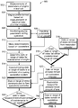
- Fig. 3 shows a method for determining maintenance of a turbine engine 500.
- the measurements of parameters of a turbine engine are taken in a test cell prior to use of the turbine engine.
- an engine profile is formed based the measurements or on historical data of similar engines and inputted or communicated to the controllers of a control system.
- a controller monitors parameters of the engine during operation. These parameters can include engine temperature, different air temperatures at the engine, fuel consumption and the like.
- parameters of the aircraft are inputted and communicated to controllers in the control system. These parameters include environmental conditions during flight, flight durations, air speeds and the like.
- a controller makes determinations based on the parameters of the engine and the aircraft (for such an embodiment). Based on these determinations the controller determines a date or a range of dates for maintenance of the engine to restore a coating at 512.
- the determined date or range of dates is communicated to a controller of a coating restoration system.
- the controller of the coating restoration system compares the date or dates communicated to pre-determined maintenance date of the engine to determine if the initial determined date or range of dates falls within a range of dates prior to the pre-determined maintenance.
- the controller of the coating restoration system cancels the date or range of dates determined and removes the engine or aircraft (in such an embodiment) from a restoration schedule. If at 516, the initial determined date or range of dates does not fall within the range of dates prior to the pre-determined maintenance, at 520 the controller of the coating restoration system leaves the determined date on the restoration schedule.
- the updated restoration schedule is communicated to a fleet operation controller.
- the fleet operation controller determines the percentage of aircraft in the fleet that are on the restoration schedule for the date or range of dates from maintenance.
- the fleet operation controller will delay the restoration for a predetermined amount of time when the percentage falls below the threshold percentage.
- the fleet operation controller leaves the determined date or range of dates on the restoration schedule.
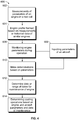
- Fig. 4 shows a flow chart of a method of restoring a coating 600.
- the measurements of parameters of a turbine engine are taken in a test cell prior to use of the turbine engine.
- an engine profile is formed based the measurements or historical data of similar engines and inputted or communicated to the controllers of a control system.
- a controller monitors parameters of the engine during operation. These parameters can include engine temperature, different air temperatures at the engine, fuel consumption and the like.
- parameters of the aircraft are inputted and communicated to controllers in the control system. These parameters include environmental conditions during flight, flight durations, air speeds and the like.
- a controller makes determinations based on the parameters of the engine and the aircraft. Based on these determinations the control system determines a date or a range of dates for maintenance of the engine to restore a coating at 612.
- the controller of a coating restoration system determines based on the date of restoration and the determinations based on engine and aircraft parameters the surfaces of the engine to be coated, the amount of coating to be supplied and/or the consistency of the coating materials.
- test cell measurements are taken of the engine and inputted into the either the engine optimization controller, engine monitoring controller or both. This information is then communicated wirelessly to all of the controllers in the control system.
- the engine is utilized for the first time on January 1 st .
- the engine monitoring controller receives inputs from the aircraft engine controller regarding flight information, including but not limited to environmental conditions including temperature and precipitation at take-off and landing, date and time of flight, air temperature changes, relative humidity, air quality, air speed and wind conditions for each flight during operation.
- the engine monitoring controller receives inputs from engine sensors regarding the air temperature of the exhaust in the engine and fuel consumed.
- the information and data inputted and received is stored in the memory of the engine monitoring controller and communicated to the engine controller during all operations of the engine.
- the controllers utilize algorithms to determine the profile of the engine after completion of each flight based on the information and data gathered during operation and based on historical data.
- the calculated profile based on engine exhaust temperature is compared to the engine profile formed during testing, and a controller determines maintenance is not needed.
- the algorithm determines based on the historical data of the engine parameters to that date, at the current pace of wear the thermal barrier coating of the engine should be restored on Sept. 1 of the same year.
- This information is communicated to all of the controllers in the control system including the one or more controllers of the coating restoration system and the one or more fleet operation controllers.
- the one or more controllers of the coating restoration system then compare the Sept. 1 date to the regularly scheduled maintenance date of the engine, which is Jan. 1 of the next year. Because the Sept. 1 date is more than one month away, the one or more controllers of the coating restoration system schedule the engine for maintenance on Sept. 1 of this year.
- the information is then communicated to the other controllers of the control system including the one or more fleet operations controllers.
- the one or more fleet operations controllers receive the information that the engine is scheduled for restoration of the thermal barrier coating on Sept. 1 of this year. The fleet operations controller then calculates the percentage of aircraft in the fleet that are currently scheduled for maintenance on Sept. 1 is 2% or less than the 3% threshold percentage of aircraft in the fleet undergoing maintenance for that day. As a result, the fleet operations controller does not change the date of the scheduled maintenance and the engine is scheduled for maintenance on Sept. 1. On the day of maintenance, the one or more controllers of the coating restoration system have the coating restoration system provide the pre-determined amount of coating of the engine to restore the engine profile.
- a controller makes an initial determination that the maintenance is to occur on Sept. 1 of this year.
- the engine profile is determined as a result of monitoring the thermal barrier coating using methods outlined in U.S. Pat. No. 9,395,301 .
- the one or more controllers of the restoration system determines that regularly scheduled maintenance is not until Jan. 1 of next year and leaves the aircraft on the restoration schedule for maintenance for Sept. 1 of this year and communicates this information to the fleet operations controller.
- the fleet operations controller calculates the percentage of aircraft scheduled for maintenance is 4%, above the threshold percentage of aircraft. The fleet operations controller then determines the maintenance date to be Oct.
- the one or more controllers of the coating restoration system restores the thermal barrier coating by increasing the amount of coating and surface area of the engine the spray device covers compared to the amount of coating and surface area coated if the maintenance occurred on Sept. 1 as was originally scheduled. In this manner, the coating restoration system compensates for the late maintenance by enhancing the restoration.
- a controller makes an initial determination that the maintenance is to occur in a range of dates between Dec. 7-14 of this year. These initial dates of maintenance are scheduled and communicated to the other controllers including the one or more controllers of the coating restoration system.
- the one or more controllers of the coating restoration system compares the scheduled range of dates to the regularly scheduled maintenance of the engine on Jan. 1 of the next year and determines this is within one month of the regularly scheduled maintenance.
- the one or more controllers of the coating restoration system moves the maintenance of the thermal barrier coating to the date of the regularly scheduled maintenance, cancelling the Dec. 7-14 maintenance.
- the amount of coating and surface area of the engine the spray device covers increases based on the later maintenance date scheduled compared to the original date calculated by engine monitoring controller. Thus, additional protection is provided.
- the algorithm makes an initial determination that the maintenance is not to occur until Feb. 1 of the next year.
- This initial date of maintenance is scheduled and communicated to the other controllers including the one or more controllers of the coating restoration system.
- the one or more controllers of the coating restoration system compares the scheduled date to the regularly scheduled maintenance of the engine on Jan. 1 of the next year and determines this is after the regularly scheduled maintenance.
- the one or more controllers of the coating restoration system moves the maintenance of the thermal barrier coating to the date of the regularly scheduled maintenance, cancelling the Feb. 1 maintenance.
- the amount of coating and surface area of the engine the spray device covers decreases compared to the amount and surface area if maintenance would have occurred on Feb. 1.
- the restoration application is altered.
- the engine monitoring controller monitors the amount of engine cycles and the average ambient temperature of the plane during operation. Based on these parameters the control system utilizes a look up table to determine a maintenance date for the engine.
- the engine monitoring controller or the engine optimization controller monitors historical data or real time data of engine and airplane parameters.
- Such parameters include one or more of an engine exhaust temperature, a condition of the coating of the engine, engine fuel flow, compressor exit pressure, compressor exit temperature, engine derating, engine speed, engine cycles, engine power use, environmental conditions, ambient airplane temperature or dates of engine use.
- the control system determines a maintenance date for the engine. The system on the maintenance date applies an additive to increase the useful life of the engine to greater than 100%.
- an initial coating on or in an engine has a useful life of 1,000 engine cycles but, after some use of the engine the coating has a remaining useful life of 750 engine cycles
- application of the additive to the coating may increase the useful life of the coating to 1,100 total engine cycles or may increase the useful life by an additional 300 engine cycles such that the actual total useful life of the coating is extended beyond the initial 100%.
- the determination of when to extend a useful life of a coating in or on an engine may not be based on a static or absolute date, but may be a relative time. For example, due to different engines being used different amounts, identical coatings on different engines may need restoration or application of additives at different times.
- the one or more controllers described herein may direct application of the additive to a coating as a number of engine cycles.
- the additive may need to be applied before expiration or upon expiration of the number of engine cycles.
- one or more controllers described herein may direct application of the additive to a coating as a trigger point.
- the trigger point can be a point in time at which the additive should be applied to the coating before continued use of the engine after the trigger point occurs.
- a trigger point can be a number of engine cycles, a number of hours of engine usage, or the like.
- a control system has one or more controllers configured to determine when to extend a life span of a coating of an engine by applying an additive to the coating based on one or more monitored parameters of the engine.
- the one or more controllers also are configured to, direct application of the additive onto a coating of the engine based on the monitored parameters of the engine.
- the coating is a thermal barrier coating.
- the one or more controllers include an engine optimization controller and a fleet operation controller.
- the engine optimization controller is configured to determine an initial maintenance date and the fleet operation controller is configured to determine the maintenance date. In one embodiment, the determined maintenance date is later than the initial maintenance date.
- the one are more controllers are configured to increase the amount of coating sprayed on the engine based on the maintenance date determined by the fleet operation controller.
- the one or more controllers include an engine optimization controller and a controller of a restorative coating system.
- the engine optimization controller determines an initial maintenance date based on the monitored parameters of the engine and the controller of the restorative coating system is configured to determine the maintenance date. In one embodiment, the determined maintenance date is later than the initial maintenance date.
- the one are more controllers are configured to increase the amount of coating sprayed on the engine based on the maintenance date determined by the controller of the restorative coating system.
- the monitored parameter of the engine includes one or more of an engine exhaust temperature, a condition of the coating of the engine, engine fuel flow, compressor exit pressure, compressor exit temperature, engine derating, engine speed, engine cycles, engine power use, environmental conditions, ambient airplane temperature or dates of engine use.
- the one or more controllers are configured to determine an amount of additive to apply onto the coating based on the monitored parameters. In another embodiment, the one or more controllers are configured to determine the type of additive to apply onto the coating based on the monitored parameters.
- a method of coating an engine includes monitoring engine parameters with one or more controllers and determining an engine maintenance date with the one or more controllers based on the monitored engine parameters.
- a coating restoration system having a mobile spray device is provided and coats the engine with the spray device on the engine maintenance date based on the monitored engine parameters.
- the method additionally provides the step of determining the engine maintenance date comprises the steps of testing the engine to form an engine profile and comparing the monitored engine parameters to the formed engine profile to determine an initial engine maintenance date.
- the initial maintenance date is communicated to a fleet operation controller and the percentage of aircraft in a fleet undergoing maintenance on the engine maintenance date is determined.
- the engine maintenance date is then determined based of the percentage of aircraft in a fleet undergoing maintenance on the engine maintenance date. In one embodiment, when the percentage of aircraft is above a threshold percentage the determined engine maintenance date is different than the initial engine maintenance date.
- the step of determining the engine maintenance date comprises the steps of testing the engine to form an engine profile and comparing the monitored engine parameters to the formed engine profile to determine an initial engine maintenance date.
- the initial maintenance date is communicated to a controller of a restorative coating system.
- the initial engine maintenance date is compared to a regularly scheduled maintenance date and the maintenance date is determined based on the regularly scheduled maintenance date.
- the determined engine maintenance date is different than the initial engine maintenance date.
- the controller of the restorative coating system can increase an amount of coating based on the engine maintenance date being different than the initial engine maintenance date.
- the controller of the restorative coating system can change a spray pattern of the spray device based on the engine maintenance date being different than the initial engine maintenance date.
- the controller of the restorative coating system can change the consistency of spray based on the engine maintenance date being different than the initial engine maintenance date.
- a control system configured with one or more controllers configured to monitor one or more parameters of an engine.
- the one or more controllers also are configured to determine an additive application to direct on the engine based on the one or more monitored parameters of the engine.
- the additive application in one embodiment extends the life of the engine to greater than 25% of a measured initial life span of the engine.
- the one or more controllers also are configured to determine when the additive application is directed on the engine.
Landscapes
- Engineering & Computer Science (AREA)
- Aviation & Aerospace Engineering (AREA)
- Mechanical Engineering (AREA)
- General Engineering & Computer Science (AREA)
- Transportation (AREA)
- Manufacturing & Machinery (AREA)
- Chemical & Material Sciences (AREA)
- Materials Engineering (AREA)
- Physics & Mathematics (AREA)
- General Physics & Mathematics (AREA)
- Automation & Control Theory (AREA)
- Combustion & Propulsion (AREA)
- Testing And Monitoring For Control Systems (AREA)
Applications Claiming Priority (1)
| Application Number | Priority Date | Filing Date | Title |
|---|---|---|---|
| US15/368,185 US10384808B2 (en) | 2016-12-02 | 2016-12-02 | Control system and method |
Publications (2)
| Publication Number | Publication Date |
|---|---|
| EP3330186A1 true EP3330186A1 (fr) | 2018-06-06 |
| EP3330186B1 EP3330186B1 (fr) | 2024-08-07 |
Family
ID=60543447
Family Applications (1)
| Application Number | Title | Priority Date | Filing Date |
|---|---|---|---|
| EP17204886.0A Active EP3330186B1 (fr) | 2016-12-02 | 2017-12-01 | Système et procédé de commande |
Country Status (4)
| Country | Link |
|---|---|
| US (1) | US10384808B2 (fr) |
| EP (1) | EP3330186B1 (fr) |
| CN (1) | CN108150229B (fr) |
| CA (1) | CA2987221A1 (fr) |
Cited By (1)
| Publication number | Priority date | Publication date | Assignee | Title |
|---|---|---|---|---|
| US11725516B2 (en) | 2019-10-18 | 2023-08-15 | Raytheon Technologies Corporation | Method of servicing a gas turbine engine or components |
Families Citing this family (14)
| Publication number | Priority date | Publication date | Assignee | Title |
|---|---|---|---|---|
| US11067002B2 (en) | 2016-12-06 | 2021-07-20 | General Electric Company | Gas turbine engine maintenance tool |
| US10534359B2 (en) | 2017-01-10 | 2020-01-14 | Honeywell International Inc. | Aircraft management systems and methods for ECS predictive maintenance |
| US10242508B2 (en) * | 2017-01-10 | 2019-03-26 | Honeywell International Inc. | Aircraft maintenance systems and methods for ECS fouling predictions |
| WO2020002915A1 (fr) * | 2018-06-29 | 2020-01-02 | Bae Systems Plc | Contrôleur de charge |
| EP3588224A1 (fr) * | 2018-06-29 | 2020-01-01 | BAE SYSTEMS plc | Contrôleur de charge |
| IL262426B2 (en) * | 2018-10-14 | 2024-08-01 | Israel Aerospace Ind Ltd | Systems and methods for controlling aircraft engines |
| WO2020197577A1 (fr) * | 2019-03-22 | 2020-10-01 | Northrop Grumman Systems Corporation | Système de surveillance d'architecture de commande de système |
| US20200356958A1 (en) * | 2019-05-08 | 2020-11-12 | Honeywell International Inc. | Usage-based maintenance system for vehicles and method of operating the same |
| US11028772B1 (en) * | 2020-01-27 | 2021-06-08 | Caterpillar Inc. | Method and system for estimating damage in an internal combustion engine |
| CN112357113A (zh) * | 2020-09-30 | 2021-02-12 | 成都飞机工业(集团)有限责任公司 | 一种用于航空发动机叶片检查的电动装置及其计数方法 |
| US12060170B2 (en) * | 2020-10-07 | 2024-08-13 | General Electric Company | Flexible engine monitoring |
| US12333225B2 (en) | 2021-02-25 | 2025-06-17 | General Electric Company | System and method for monitoring and diagnosis of engine health using a snapshot-CEOD based approach |
| DE102021202242A1 (de) | 2021-03-09 | 2022-09-15 | MTU Aero Engines AG | Vorrichtung und Verfahren zur Überwachung eines Flugzeugzustandes |
| CN113830327A (zh) * | 2021-11-23 | 2021-12-24 | 中国飞机强度研究所 | 一种飞机试验用通风装置 |
Citations (5)
| Publication number | Priority date | Publication date | Assignee | Title |
|---|---|---|---|---|
| WO2012151150A1 (fr) * | 2011-05-05 | 2012-11-08 | Siemens Energy, Inc. | Procédé pour prédire la durée de vie utile restante d'un moteur et de ses composants |
| WO2015086957A2 (fr) * | 2013-12-13 | 2015-06-18 | Snecma | Prévision d'opérations de maintenance a appliquer sur un moteur |
| EP2889711A2 (fr) * | 2013-12-30 | 2015-07-01 | Rolls-Royce Corporation | Système et procédé permettant d'optimiser la durée de vie des composants dans un système d'alimentation |
| US20160160679A1 (en) * | 2014-12-03 | 2016-06-09 | Rolls-Royce Corporation | Turbine engine fleet wash management system |
| US9395301B2 (en) | 2014-10-02 | 2016-07-19 | General Electric Company | Methods for monitoring environmental barrier coatings |
Family Cites Families (17)
| Publication number | Priority date | Publication date | Assignee | Title |
|---|---|---|---|---|
| US6010746A (en) | 1998-02-03 | 2000-01-04 | United Technologies Corporation | In-situ repair method for a turbomachinery component |
| EP1371812A1 (fr) | 2002-06-04 | 2003-12-17 | ALSTOM (Switzerland) Ltd | Procédé de réparation pour les aubes d'une turbine à gaz |
| US7582359B2 (en) | 2002-09-23 | 2009-09-01 | Siemens Energy, Inc. | Apparatus and method of monitoring operating parameters of a gas turbine |
| US8742944B2 (en) | 2004-06-21 | 2014-06-03 | Siemens Energy, Inc. | Apparatus and method of monitoring operating parameters of a gas turbine |
| US8986778B2 (en) | 2006-07-06 | 2015-03-24 | Siemens Energy, Inc. | Coating method for non-destructive examination of articles of manufacture |
| US20090169752A1 (en) | 2007-12-27 | 2009-07-02 | Ming Fu | Method for Improving Resistance to CMAS Infiltration |
| US20090252985A1 (en) | 2008-04-08 | 2009-10-08 | Bangalore Nagaraj | Thermal barrier coating system and coating methods for gas turbine engine shroud |
| US8470460B2 (en) | 2008-11-25 | 2013-06-25 | Rolls-Royce Corporation | Multilayer thermal barrier coatings |
| EP2233600B1 (fr) | 2009-03-26 | 2020-04-29 | Ansaldo Energia Switzerland AG | Procédé de protection d'un système de revêtement à barrière thermique et procédé de renouvellement de ce revêtement |
| US8221825B2 (en) | 2009-03-30 | 2012-07-17 | Alstom Technology Ltd. | Comprehensive method for local application and local repair of thermal barrier coatings |
| US9102015B2 (en) | 2013-03-14 | 2015-08-11 | Siemens Energy, Inc | Method and apparatus for fabrication and repair of thermal barriers |
| EP3077563B1 (fr) | 2013-12-06 | 2023-05-10 | Raytheon Technologies Corporation | Revêtements de barrière thermique résistants à l'aluminosilicate de calcium et de magnésium (cmas), systèmes, et procédés de production associés |
| US9347899B2 (en) | 2013-12-06 | 2016-05-24 | Rolls-Royce Corporation | Thermographic inspection techniques |
| US10060830B2 (en) | 2014-06-09 | 2018-08-28 | United Technologies Corporation | In-situ system and method of determining coating integrity of turbomachinery components |
| US20160207639A1 (en) * | 2015-01-07 | 2016-07-21 | Rolls-Royce Plc | Aircraft engine maintenance system |
| US10501169B2 (en) * | 2016-06-17 | 2019-12-10 | Pratt & Whitney Canada Corp. | Propeller blade angle control system |
| US10589300B2 (en) | 2016-12-02 | 2020-03-17 | General Electric Company | Coating system and method |
-
2016
- 2016-12-02 US US15/368,185 patent/US10384808B2/en active Active
-
2017
- 2017-11-30 CA CA2987221A patent/CA2987221A1/fr not_active Abandoned
- 2017-12-01 EP EP17204886.0A patent/EP3330186B1/fr active Active
- 2017-12-01 CN CN201711249354.XA patent/CN108150229B/zh active Active
Patent Citations (5)
| Publication number | Priority date | Publication date | Assignee | Title |
|---|---|---|---|---|
| WO2012151150A1 (fr) * | 2011-05-05 | 2012-11-08 | Siemens Energy, Inc. | Procédé pour prédire la durée de vie utile restante d'un moteur et de ses composants |
| WO2015086957A2 (fr) * | 2013-12-13 | 2015-06-18 | Snecma | Prévision d'opérations de maintenance a appliquer sur un moteur |
| EP2889711A2 (fr) * | 2013-12-30 | 2015-07-01 | Rolls-Royce Corporation | Système et procédé permettant d'optimiser la durée de vie des composants dans un système d'alimentation |
| US9395301B2 (en) | 2014-10-02 | 2016-07-19 | General Electric Company | Methods for monitoring environmental barrier coatings |
| US20160160679A1 (en) * | 2014-12-03 | 2016-06-09 | Rolls-Royce Corporation | Turbine engine fleet wash management system |
Cited By (2)
| Publication number | Priority date | Publication date | Assignee | Title |
|---|---|---|---|---|
| US11725516B2 (en) | 2019-10-18 | 2023-08-15 | Raytheon Technologies Corporation | Method of servicing a gas turbine engine or components |
| EP3808936B1 (fr) * | 2019-10-18 | 2025-04-09 | RTX Corporation | Procédé d'entretien d'un moteur à turbine à gaz ou de ses composants |
Also Published As
| Publication number | Publication date |
|---|---|
| US10384808B2 (en) | 2019-08-20 |
| CN108150229B (zh) | 2020-12-08 |
| EP3330186B1 (fr) | 2024-08-07 |
| CA2987221A1 (fr) | 2018-06-02 |
| US20180155061A1 (en) | 2018-06-07 |
| CN108150229A (zh) | 2018-06-12 |
Similar Documents
| Publication | Publication Date | Title |
|---|---|---|
| US10384808B2 (en) | Control system and method | |
| US11180265B2 (en) | Control system and method | |
| US11208917B2 (en) | Turbine engine fleet wash management system | |
| US12602037B2 (en) | Methods and apparatus to generate a predictive asset health quantifier of a turbine engine | |
| US11067592B2 (en) | Methods and apparatus for prognostic health monitoring of a turbine engine | |
| US20090048730A1 (en) | Method and system for planning repair of an engine | |
| KR101529762B1 (ko) | 비행기 부품의 성능이 쇠퇴기에 들어선 것을 검측하는 방법 | |
| US10589300B2 (en) | Coating system and method | |
| EP3435187B1 (fr) | Système de surveillance de dégradation thermique et procédé pour surveiller la dégradation thermique d'équipements | |
| US10801359B2 (en) | Method and system for identifying rub events | |
| US12291344B2 (en) | Aircraft performance optimization based on engine performance monitoring | |
| JP6205322B2 (ja) | 飛行機の補助動力ユニットの燃油ユニットの性能検出の方法と装置 | |
| JP6205319B2 (ja) | 飛行機の補助動力単元のタービン効率の監視方法と装置 | |
| EP3460215B1 (fr) | Procédé et appareil pour prédire la température de sortie de turbine d'une turbine à gaz | |
| RU2765164C1 (ru) | Контроль состояния технического ресурса воздушного винта на основе коэффициента использования | |
| EP3779124B1 (fr) | Système et procédé de commande | |
| Yang et al. | Research on MPA method in EHM system |
Legal Events
| Date | Code | Title | Description |
|---|---|---|---|
| PUAI | Public reference made under article 153(3) epc to a published international application that has entered the european phase |
Free format text: ORIGINAL CODE: 0009012 |
|
| STAA | Information on the status of an ep patent application or granted ep patent |
Free format text: STATUS: THE APPLICATION HAS BEEN PUBLISHED |
|
| AK | Designated contracting states |
Kind code of ref document: A1 Designated state(s): AL AT BE BG CH CY CZ DE DK EE ES FI FR GB GR HR HU IE IS IT LI LT LU LV MC MK MT NL NO PL PT RO RS SE SI SK SM TR |
|
| AX | Request for extension of the european patent |
Extension state: BA ME |
|
| STAA | Information on the status of an ep patent application or granted ep patent |
Free format text: STATUS: REQUEST FOR EXAMINATION WAS MADE |
|
| 17P | Request for examination filed |
Effective date: 20181206 |
|
| RBV | Designated contracting states (corrected) |
Designated state(s): AL AT BE BG CH CY CZ DE DK EE ES FI FR GB GR HR HU IE IS IT LI LT LU LV MC MK MT NL NO PL PT RO RS SE SI SK SM TR |
|
| STAA | Information on the status of an ep patent application or granted ep patent |
Free format text: STATUS: EXAMINATION IS IN PROGRESS |
|
| 17Q | First examination report despatched |
Effective date: 20190827 |
|
| GRAP | Despatch of communication of intention to grant a patent |
Free format text: ORIGINAL CODE: EPIDOSNIGR1 |
|
| STAA | Information on the status of an ep patent application or granted ep patent |
Free format text: STATUS: GRANT OF PATENT IS INTENDED |
|
| INTG | Intention to grant announced |
Effective date: 20240307 |
|
| GRAS | Grant fee paid |
Free format text: ORIGINAL CODE: EPIDOSNIGR3 |
|
| GRAA | (expected) grant |
Free format text: ORIGINAL CODE: 0009210 |
|
| STAA | Information on the status of an ep patent application or granted ep patent |
Free format text: STATUS: THE PATENT HAS BEEN GRANTED |
|
| AK | Designated contracting states |
Kind code of ref document: B1 Designated state(s): AL AT BE BG CH CY CZ DE DK EE ES FI FR GB GR HR HU IE IS IT LI LT LU LV MC MK MT NL NO PL PT RO RS SE SI SK SM TR |
|
| REG | Reference to a national code |
Ref country code: GB Ref legal event code: FG4D |
|
| REG | Reference to a national code |
Ref country code: CH Ref legal event code: EP |
|
| P01 | Opt-out of the competence of the unified patent court (upc) registered |
Free format text: CASE NUMBER: APP_41836/2024 Effective date: 20240716 |
|
| REG | Reference to a national code |
Ref country code: IE Ref legal event code: FG4D |
|
| REG | Reference to a national code |
Ref country code: DE Ref legal event code: R096 Ref document number: 602017083847 Country of ref document: DE |
|
| REG | Reference to a national code |
Ref country code: LT Ref legal event code: MG9D |
|
| REG | Reference to a national code |
Ref country code: NL Ref legal event code: MP Effective date: 20240807 |
|
| PG25 | Lapsed in a contracting state [announced via postgrant information from national office to epo] |
Ref country code: NO Free format text: LAPSE BECAUSE OF FAILURE TO SUBMIT A TRANSLATION OF THE DESCRIPTION OR TO PAY THE FEE WITHIN THE PRESCRIBED TIME-LIMIT Effective date: 20241107 |
|
| REG | Reference to a national code |
Ref country code: AT Ref legal event code: MK05 Ref document number: 1710673 Country of ref document: AT Kind code of ref document: T Effective date: 20240807 |
|
| PG25 | Lapsed in a contracting state [announced via postgrant information from national office to epo] |
Ref country code: PL Free format text: LAPSE BECAUSE OF FAILURE TO SUBMIT A TRANSLATION OF THE DESCRIPTION OR TO PAY THE FEE WITHIN THE PRESCRIBED TIME-LIMIT Effective date: 20240807 Ref country code: FI Free format text: LAPSE BECAUSE OF FAILURE TO SUBMIT A TRANSLATION OF THE DESCRIPTION OR TO PAY THE FEE WITHIN THE PRESCRIBED TIME-LIMIT Effective date: 20240807 Ref country code: PT Free format text: LAPSE BECAUSE OF FAILURE TO SUBMIT A TRANSLATION OF THE DESCRIPTION OR TO PAY THE FEE WITHIN THE PRESCRIBED TIME-LIMIT Effective date: 20241209 Ref country code: GR Free format text: LAPSE BECAUSE OF FAILURE TO SUBMIT A TRANSLATION OF THE DESCRIPTION OR TO PAY THE FEE WITHIN THE PRESCRIBED TIME-LIMIT Effective date: 20241108 Ref country code: NL Free format text: LAPSE BECAUSE OF FAILURE TO SUBMIT A TRANSLATION OF THE DESCRIPTION OR TO PAY THE FEE WITHIN THE PRESCRIBED TIME-LIMIT Effective date: 20240807 |
|
| PG25 | Lapsed in a contracting state [announced via postgrant information from national office to epo] |
Ref country code: BG Free format text: LAPSE BECAUSE OF FAILURE TO SUBMIT A TRANSLATION OF THE DESCRIPTION OR TO PAY THE FEE WITHIN THE PRESCRIBED TIME-LIMIT Effective date: 20240807 |
|
| PG25 | Lapsed in a contracting state [announced via postgrant information from national office to epo] |
Ref country code: LV Free format text: LAPSE BECAUSE OF FAILURE TO SUBMIT A TRANSLATION OF THE DESCRIPTION OR TO PAY THE FEE WITHIN THE PRESCRIBED TIME-LIMIT Effective date: 20240807 |
|
| PG25 | Lapsed in a contracting state [announced via postgrant information from national office to epo] |
Ref country code: AT Free format text: LAPSE BECAUSE OF FAILURE TO SUBMIT A TRANSLATION OF THE DESCRIPTION OR TO PAY THE FEE WITHIN THE PRESCRIBED TIME-LIMIT Effective date: 20240807 Ref country code: IS Free format text: LAPSE BECAUSE OF FAILURE TO SUBMIT A TRANSLATION OF THE DESCRIPTION OR TO PAY THE FEE WITHIN THE PRESCRIBED TIME-LIMIT Effective date: 20241207 |
|
| PG25 | Lapsed in a contracting state [announced via postgrant information from national office to epo] |
Ref country code: HR Free format text: LAPSE BECAUSE OF FAILURE TO SUBMIT A TRANSLATION OF THE DESCRIPTION OR TO PAY THE FEE WITHIN THE PRESCRIBED TIME-LIMIT Effective date: 20240807 |
|
| PG25 | Lapsed in a contracting state [announced via postgrant information from national office to epo] |
Ref country code: ES Free format text: LAPSE BECAUSE OF FAILURE TO SUBMIT A TRANSLATION OF THE DESCRIPTION OR TO PAY THE FEE WITHIN THE PRESCRIBED TIME-LIMIT Effective date: 20240807 Ref country code: RS Free format text: LAPSE BECAUSE OF FAILURE TO SUBMIT A TRANSLATION OF THE DESCRIPTION OR TO PAY THE FEE WITHIN THE PRESCRIBED TIME-LIMIT Effective date: 20241107 |
|
| PG25 | Lapsed in a contracting state [announced via postgrant information from national office to epo] |
Ref country code: RS Free format text: LAPSE BECAUSE OF FAILURE TO SUBMIT A TRANSLATION OF THE DESCRIPTION OR TO PAY THE FEE WITHIN THE PRESCRIBED TIME-LIMIT Effective date: 20241107 Ref country code: PT Free format text: LAPSE BECAUSE OF FAILURE TO SUBMIT A TRANSLATION OF THE DESCRIPTION OR TO PAY THE FEE WITHIN THE PRESCRIBED TIME-LIMIT Effective date: 20241209 Ref country code: PL Free format text: LAPSE BECAUSE OF FAILURE TO SUBMIT A TRANSLATION OF THE DESCRIPTION OR TO PAY THE FEE WITHIN THE PRESCRIBED TIME-LIMIT Effective date: 20240807 Ref country code: NO Free format text: LAPSE BECAUSE OF FAILURE TO SUBMIT A TRANSLATION OF THE DESCRIPTION OR TO PAY THE FEE WITHIN THE PRESCRIBED TIME-LIMIT Effective date: 20241107 Ref country code: NL Free format text: LAPSE BECAUSE OF FAILURE TO SUBMIT A TRANSLATION OF THE DESCRIPTION OR TO PAY THE FEE WITHIN THE PRESCRIBED TIME-LIMIT Effective date: 20240807 Ref country code: LV Free format text: LAPSE BECAUSE OF FAILURE TO SUBMIT A TRANSLATION OF THE DESCRIPTION OR TO PAY THE FEE WITHIN THE PRESCRIBED TIME-LIMIT Effective date: 20240807 Ref country code: IS Free format text: LAPSE BECAUSE OF FAILURE TO SUBMIT A TRANSLATION OF THE DESCRIPTION OR TO PAY THE FEE WITHIN THE PRESCRIBED TIME-LIMIT Effective date: 20241207 Ref country code: HR Free format text: LAPSE BECAUSE OF FAILURE TO SUBMIT A TRANSLATION OF THE DESCRIPTION OR TO PAY THE FEE WITHIN THE PRESCRIBED TIME-LIMIT Effective date: 20240807 Ref country code: GR Free format text: LAPSE BECAUSE OF FAILURE TO SUBMIT A TRANSLATION OF THE DESCRIPTION OR TO PAY THE FEE WITHIN THE PRESCRIBED TIME-LIMIT Effective date: 20241108 Ref country code: FI Free format text: LAPSE BECAUSE OF FAILURE TO SUBMIT A TRANSLATION OF THE DESCRIPTION OR TO PAY THE FEE WITHIN THE PRESCRIBED TIME-LIMIT Effective date: 20240807 Ref country code: ES Free format text: LAPSE BECAUSE OF FAILURE TO SUBMIT A TRANSLATION OF THE DESCRIPTION OR TO PAY THE FEE WITHIN THE PRESCRIBED TIME-LIMIT Effective date: 20240807 Ref country code: BG Free format text: LAPSE BECAUSE OF FAILURE TO SUBMIT A TRANSLATION OF THE DESCRIPTION OR TO PAY THE FEE WITHIN THE PRESCRIBED TIME-LIMIT Effective date: 20240807 Ref country code: AT Free format text: LAPSE BECAUSE OF FAILURE TO SUBMIT A TRANSLATION OF THE DESCRIPTION OR TO PAY THE FEE WITHIN THE PRESCRIBED TIME-LIMIT Effective date: 20240807 |
|
| PG25 | Lapsed in a contracting state [announced via postgrant information from national office to epo] |
Ref country code: SM Free format text: LAPSE BECAUSE OF FAILURE TO SUBMIT A TRANSLATION OF THE DESCRIPTION OR TO PAY THE FEE WITHIN THE PRESCRIBED TIME-LIMIT Effective date: 20240807 Ref country code: DK Free format text: LAPSE BECAUSE OF FAILURE TO SUBMIT A TRANSLATION OF THE DESCRIPTION OR TO PAY THE FEE WITHIN THE PRESCRIBED TIME-LIMIT Effective date: 20240807 Ref country code: RO Free format text: LAPSE BECAUSE OF FAILURE TO SUBMIT A TRANSLATION OF THE DESCRIPTION OR TO PAY THE FEE WITHIN THE PRESCRIBED TIME-LIMIT Effective date: 20240807 |
|
| PG25 | Lapsed in a contracting state [announced via postgrant information from national office to epo] |
Ref country code: EE Free format text: LAPSE BECAUSE OF FAILURE TO SUBMIT A TRANSLATION OF THE DESCRIPTION OR TO PAY THE FEE WITHIN THE PRESCRIBED TIME-LIMIT Effective date: 20240807 |
|
| PG25 | Lapsed in a contracting state [announced via postgrant information from national office to epo] |
Ref country code: CZ Free format text: LAPSE BECAUSE OF FAILURE TO SUBMIT A TRANSLATION OF THE DESCRIPTION OR TO PAY THE FEE WITHIN THE PRESCRIBED TIME-LIMIT Effective date: 20240807 |
|
| PG25 | Lapsed in a contracting state [announced via postgrant information from national office to epo] |
Ref country code: SK Free format text: LAPSE BECAUSE OF FAILURE TO SUBMIT A TRANSLATION OF THE DESCRIPTION OR TO PAY THE FEE WITHIN THE PRESCRIBED TIME-LIMIT Effective date: 20240807 |
|
| REG | Reference to a national code |
Ref country code: DE Ref legal event code: R097 Ref document number: 602017083847 Country of ref document: DE |
|
| PLBE | No opposition filed within time limit |
Free format text: ORIGINAL CODE: 0009261 |
|
| STAA | Information on the status of an ep patent application or granted ep patent |
Free format text: STATUS: NO OPPOSITION FILED WITHIN TIME LIMIT |
|
| PG25 | Lapsed in a contracting state [announced via postgrant information from national office to epo] |
Ref country code: MC Free format text: LAPSE BECAUSE OF FAILURE TO SUBMIT A TRANSLATION OF THE DESCRIPTION OR TO PAY THE FEE WITHIN THE PRESCRIBED TIME-LIMIT Effective date: 20240807 |
|
| 26N | No opposition filed |
Effective date: 20250508 |
|
| REG | Reference to a national code |
Ref country code: CH Ref legal event code: PL |
|
| PG25 | Lapsed in a contracting state [announced via postgrant information from national office to epo] |
Ref country code: LU Free format text: LAPSE BECAUSE OF NON-PAYMENT OF DUE FEES Effective date: 20241201 |
|
| PG25 | Lapsed in a contracting state [announced via postgrant information from national office to epo] |
Ref country code: SE Free format text: LAPSE BECAUSE OF FAILURE TO SUBMIT A TRANSLATION OF THE DESCRIPTION OR TO PAY THE FEE WITHIN THE PRESCRIBED TIME-LIMIT Effective date: 20240807 |
|
| REG | Reference to a national code |
Ref country code: BE Ref legal event code: MM Effective date: 20241231 |
|
| PG25 | Lapsed in a contracting state [announced via postgrant information from national office to epo] |
Ref country code: BE Free format text: LAPSE BECAUSE OF NON-PAYMENT OF DUE FEES Effective date: 20241231 |
|
| PG25 | Lapsed in a contracting state [announced via postgrant information from national office to epo] |
Ref country code: CH Free format text: LAPSE BECAUSE OF NON-PAYMENT OF DUE FEES Effective date: 20241231 |
|
| PG25 | Lapsed in a contracting state [announced via postgrant information from national office to epo] |
Ref country code: IE Free format text: LAPSE BECAUSE OF NON-PAYMENT OF DUE FEES Effective date: 20241201 |
|
| PGFP | Annual fee paid to national office [announced via postgrant information from national office to epo] |
Ref country code: DE Payment date: 20251126 Year of fee payment: 9 |
|
| PGFP | Annual fee paid to national office [announced via postgrant information from national office to epo] |
Ref country code: GB Payment date: 20251120 Year of fee payment: 9 |
|
| PGFP | Annual fee paid to national office [announced via postgrant information from national office to epo] |
Ref country code: FR Payment date: 20251119 Year of fee payment: 9 |
|
| PG25 | Lapsed in a contracting state [announced via postgrant information from national office to epo] |
Ref country code: IT Free format text: LAPSE BECAUSE OF FAILURE TO SUBMIT A TRANSLATION OF THE DESCRIPTION OR TO PAY THE FEE WITHIN THE PRESCRIBED TIME-LIMIT Effective date: 20240807 |
|
| PG25 | Lapsed in a contracting state [announced via postgrant information from national office to epo] |
Ref country code: CY Free format text: LAPSE BECAUSE OF FAILURE TO SUBMIT A TRANSLATION OF THE DESCRIPTION OR TO PAY THE FEE WITHIN THE PRESCRIBED TIME-LIMIT; INVALID AB INITIO Effective date: 20171201 |