EP3330203B1 - Courroie de transporteur à recouvrement maillé et entraînement de bord - Google Patents
Courroie de transporteur à recouvrement maillé et entraînement de bord Download PDFInfo
- Publication number
- EP3330203B1 EP3330203B1 EP17190882.5A EP17190882A EP3330203B1 EP 3330203 B1 EP3330203 B1 EP 3330203B1 EP 17190882 A EP17190882 A EP 17190882A EP 3330203 B1 EP3330203 B1 EP 3330203B1
- Authority
- EP
- European Patent Office
- Prior art keywords
- belt
- clips
- conveyor belt
- hold
- edge
- Prior art date
- Legal status (The legal status is an assumption and is not a legal conclusion. Google has not performed a legal analysis and makes no representation as to the accuracy of the status listed.)
- Active
Links
Images




Classifications
-
- B—PERFORMING OPERATIONS; TRANSPORTING
- B65—CONVEYING; PACKING; STORING; HANDLING THIN OR FILAMENTARY MATERIAL
- B65G—TRANSPORT OR STORAGE DEVICES, e.g. CONVEYORS FOR LOADING OR TIPPING, SHOP CONVEYOR SYSTEMS OR PNEUMATIC TUBE CONVEYORS
- B65G15/00—Conveyors having endless load-conveying surfaces, i.e. belts and like continuous members, to which tractive effort is transmitted by means other than endless driving elements of similar configuration
- B65G15/30—Belts or like endless load-carriers
- B65G15/48—Belts or like endless load-carriers metallic
-
- B—PERFORMING OPERATIONS; TRANSPORTING
- B65—CONVEYING; PACKING; STORING; HANDLING THIN OR FILAMENTARY MATERIAL
- B65G—TRANSPORT OR STORAGE DEVICES, e.g. CONVEYORS FOR LOADING OR TIPPING, SHOP CONVEYOR SYSTEMS OR PNEUMATIC TUBE CONVEYORS
- B65G17/00—Conveyors having an endless traction element, e.g. a chain, transmitting movement to a continuous or substantially-continuous load-carrying surface or to a series of individual load-carriers; Endless-chain conveyors in which the chains form the load-carrying surface
- B65G17/30—Details; Auxiliary devices
- B65G17/38—Chains or like traction elements; Connections between traction elements and load-carriers
- B65G17/42—Attaching load carriers to traction elements
-
- B—PERFORMING OPERATIONS; TRANSPORTING
- B65—CONVEYING; PACKING; STORING; HANDLING THIN OR FILAMENTARY MATERIAL
- B65G—TRANSPORT OR STORAGE DEVICES, e.g. CONVEYORS FOR LOADING OR TIPPING, SHOP CONVEYOR SYSTEMS OR PNEUMATIC TUBE CONVEYORS
- B65G15/00—Conveyors having endless load-conveying surfaces, i.e. belts and like continuous members, to which tractive effort is transmitted by means other than endless driving elements of similar configuration
- B65G15/30—Belts or like endless load-carriers
- B65G15/54—Endless load-carriers made of interwoven ropes or wires
-
- B—PERFORMING OPERATIONS; TRANSPORTING
- B65—CONVEYING; PACKING; STORING; HANDLING THIN OR FILAMENTARY MATERIAL
- B65G—TRANSPORT OR STORAGE DEVICES, e.g. CONVEYORS FOR LOADING OR TIPPING, SHOP CONVEYOR SYSTEMS OR PNEUMATIC TUBE CONVEYORS
- B65G15/00—Conveyors having endless load-conveying surfaces, i.e. belts and like continuous members, to which tractive effort is transmitted by means other than endless driving elements of similar configuration
- B65G15/30—Belts or like endless load-carriers
- B65G15/56—Belts or like endless load-carriers with edge-protecting or reinforcing means
-
- B—PERFORMING OPERATIONS; TRANSPORTING
- B65—CONVEYING; PACKING; STORING; HANDLING THIN OR FILAMENTARY MATERIAL
- B65G—TRANSPORT OR STORAGE DEVICES, e.g. CONVEYORS FOR LOADING OR TIPPING, SHOP CONVEYOR SYSTEMS OR PNEUMATIC TUBE CONVEYORS
- B65G17/00—Conveyors having an endless traction element, e.g. a chain, transmitting movement to a continuous or substantially-continuous load-carrying surface or to a series of individual load-carriers; Endless-chain conveyors in which the chains form the load-carrying surface
- B65G17/06—Conveyors having an endless traction element, e.g. a chain, transmitting movement to a continuous or substantially-continuous load-carrying surface or to a series of individual load-carriers; Endless-chain conveyors in which the chains form the load-carrying surface having a load-carrying surface formed by a series of interconnected, e.g. longitudinal, links, plates, or platforms
- B65G17/063—Conveyors having an endless traction element, e.g. a chain, transmitting movement to a continuous or substantially-continuous load-carrying surface or to a series of individual load-carriers; Endless-chain conveyors in which the chains form the load-carrying surface having a load-carrying surface formed by a series of interconnected, e.g. longitudinal, links, plates, or platforms the load carrying surface being formed by profiles, rods, bars, rollers or the like attached to more than one traction element
- B65G17/064—Conveyors having an endless traction element, e.g. a chain, transmitting movement to a continuous or substantially-continuous load-carrying surface or to a series of individual load-carriers; Endless-chain conveyors in which the chains form the load-carrying surface having a load-carrying surface formed by a series of interconnected, e.g. longitudinal, links, plates, or platforms the load carrying surface being formed by profiles, rods, bars, rollers or the like attached to more than one traction element the profiles, rods, bars, rollers or the like being interconnected by a mesh or grid-like structure
-
- B—PERFORMING OPERATIONS; TRANSPORTING
- B65—CONVEYING; PACKING; STORING; HANDLING THIN OR FILAMENTARY MATERIAL
- B65G—TRANSPORT OR STORAGE DEVICES, e.g. CONVEYORS FOR LOADING OR TIPPING, SHOP CONVEYOR SYSTEMS OR PNEUMATIC TUBE CONVEYORS
- B65G17/00—Conveyors having an endless traction element, e.g. a chain, transmitting movement to a continuous or substantially-continuous load-carrying surface or to a series of individual load-carriers; Endless-chain conveyors in which the chains form the load-carrying surface
- B65G17/30—Details; Auxiliary devices
- B65G17/46—Means for holding or retaining the loads in fixed position on the load-carriers, e.g. magnetic
-
- B—PERFORMING OPERATIONS; TRANSPORTING
- B65—CONVEYING; PACKING; STORING; HANDLING THIN OR FILAMENTARY MATERIAL
- B65G—TRANSPORT OR STORAGE DEVICES, e.g. CONVEYORS FOR LOADING OR TIPPING, SHOP CONVEYOR SYSTEMS OR PNEUMATIC TUBE CONVEYORS
- B65G23/00—Driving gear for endless conveyors; Belt- or chain-tensioning arrangements
- B65G23/02—Belt- or chain-engaging elements
- B65G23/04—Drums, rollers, or wheels
- B65G23/06—Drums, rollers, or wheels with projections engaging abutments on belts or chains, e.g. sprocket wheels
Definitions
- the present disclosure is directed to a conveyor belt, and more particularly to an edge drive mesh overlay conveyor belt for maintaining belt orientation and providing improved positive edge drive capability.
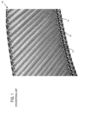
- a spiral overlay or mesh overlay conveyor belt 10 is comprised of wire spirals 12 intermeshed together by connecting rods 14 extending across the conveyor belt in the transverse direction.
- the ends of the rods extend through links 16 which pivotally connect adjacent rods, and are arranged along the side edges of the conveyor.
- the links also serve as tractive links in that they engage the sprockets which drive the conveyor.
- Fatigue failure on the positively driven edge of the mesh overlay belt has been a concern in the past, as well as maintaining the belt in the proper position on the spiral conveyor.
- a conveyor belt comprising a plurality of spaced tractive rods; a plurality of rows transversely disposed with respect to a direction of travel and interconnecting said plurality of spaced tractive rods; a plurality of belt drive clips; and wherein each of said rows comprises a U-shaped link on each edge and a mesh overlay extending therebetween.
- at least some of the U-shaped links include an integral hold-down clip; wherein said conveyor belt includes opposing first and second outer edges and said plurality of belt drive clips and/or U-shaped links with the integral hold-down clip are disposed on at least one of the first and second outer edges of the conveyor belt.
- a conveyor belt with improved edge drive capability said conveyor belt comprising a plurality of spaced tractive rods; a plurality of pitch rows transversely disposed with respect to a direction of travel and interconnecting said plurality of spaced tractive rods; and a plurality of belt drive clips; wherein each of said rows comprises a U-shaped link on each edge and a mesh overlay extending therebetween; wherein at least some of the U-shaped links include an edge guard; and wherein said conveyor belt includes opposing first and second outer edges and said plurality of belt drive clips and/or U-shaped links with the integral hold-down clip are disposed on at least one of the first and second outer edges of the conveyor belt.
- the invention is defined by the conveyor belt according to claim 1.
- the belt drive clips 50 are preferably formed in a J-shape on every pitch, or support row, and a hold-down clip 60 is preferably positioned every third pitch, or support row, in an overlapping pattern. Other patterns such as every pitch, every other pitch, etc., could also be used.
- a standard reinforcing bar 140, or a plurality of bars, may also be inserted into the belt 100 on those pitches, or support row, where no hold-down clip 60 is used.
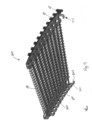
- Conveyor belt 100 preferably comprises a mesh overlay conveyor belt, although other belt types and configurations could of course be used.
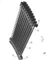
- Conveyor belt 100 includes a plurality of spaced tractive rods 180 disposed in succession and transversely with respect to a direction of travel T as represented by arrow T of belt 100, each rod 180 having two ends, each preferably terminating in a buttonhead 210.
- Belt 100 includes a plurality of support rows 160 transversely disposed with respect to the direction of travel T, and interconnecting the succession of rods 180.
- Each row 160 is comprised of a plurality of U-shaped links 170, each link connecting a rod 180 with a following rod in the succession. More preferably, each row 160 includes at least one link 170 on each end and a mesh overlay 190 extending therebetween.
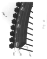
- belt 100 preferably includes one or more rows including a J-shaped belt drive clip 50, a hold-down clip 60 and a reinforcing bar 140 disposed along at least one edge of the conveyor belt. Belt drive clips 50, hold-down clips 60 and reinforcing bars 140 can be positioned along both edges of the conveyor belt (as shown in FIG.
- the conveyor belt 100 may include only belt drive clips 50 and reinforcing bars 140 or, alternatively, only hold-down clips 60 and reinforcing bars 140.
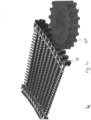
- belt 200 includes hold-down clips 60 along one edge (interior edge) and belt drive clips 50 and hold-down clips 60 along the other edge (exterior edge).
- belt 100, 200 may be manufactured without any reinforcing bars or alternatively, several rows of reinforcing bars may be provided, depending upon the particular application.
- any combination of belt drive clips, hold-down clips and/or reinforcing bars may be used depending upon the particular application for which the conveyor belt is intended.
- the combination of overlapping J-shaped drive clips and hold-down clips on the outer edge(s) of the conveyor belt with a welded U-shaped link and rod assembly provide support for the position of the metal mesh overlay.
- the rows of clips and bars along the outer, tension-bearing belt edge provide superior strength to offset the belt tension that results during system operation.
- the welded assembly of inner and outer U-shaped links and rods provides a structure that eliminates the possibility for excess lateral movement of the rows of bars and links from the inside or outside belt edges while at the same time provides surfaces where the belt can contact the stationary support rails (described further below). It is preferred for the U-shaped links to contact the support rails rather than the mesh overlay in order to reduce the contact pressure between the belt and rail, reducing also the likelihood of component wear.
- the belt is driven forward by the engagement with sprockets positioned along the outer periphery of the belt's spiral path. If needed, the belt can also be driven from the top side or underneath using different sprockets to engage the U-shaped links along the belt edges.
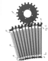
- the J-shaped drive clips 50 are engaged by sprocket 500 driven by a vertically-oriented shaft of a spindle drive (not shown), while the hold-down clips 60 serve to maintain the belt 100, 200 in proper orientation both laterally and vertically relative to the sprocket 500.
- a vertical extension portion of the hold-down clip 60 supports the reaction loading on the belt 100 as a result of engagement with a support rail 510 ( FIG. 8 ).
- the upstanding member 68 of the hold-down clip 60 as it extends below the thickness of the belt 100 is typically positioned against a stationary support rail 510 and prevents the belt 100 from inadvertently lifting off of the support rail 510.
- the opposing wings 66 on each side of the hold-down clip 60 are provided to ensure a smooth engagement with the rail 510 regardless of the driven direction of the belt 100.
- Both the belt drive clip 50 and the hold-down clip 60 are positioned in an overlapping pattern along with additional reinforcing bars 140 to act as load carrying members, especially during those times when the belt 100 is partially collapsed, as in a turn for example.
- Conveyor belt 300 preferably comprises a mesh overlay conveyor belt as described above, although other belt types and configurations could of course be used.
- Conveyor belt 300 includes a plurality of spaced tractive rods 180 disposed in succession and transversely with respect to a direction of travel of belt 300, each rod 180 having two ends preferably terminating in a buttonhead 210.
- Belt 300 includes a plurality of support rows 360 transversely disposed with respect to the direction of travel T, and interconnecting the succession of rods 180.
- Belt 300 preferably includes at least one row of J-shaped belt drive clips 50 disposed along at least one edge of the conveyor belt.
- Each row 360 is comprised of a plurality of links 310, each link connecting a rod 180 with a following rod in the succession. More preferably, each pitch or row 360 includes at least one link 310 on each end and a mesh overlay 190 preferably extending therebetween.
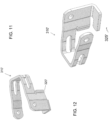
- Link 310 includes an integral hold-down clip 315 comprising a depending extension 320 and an upstanding tab member 325. The depending extension 320 supports the reaction loading on the belt 300 as a result of engagement with the support rail 510.
- the upstanding tab member 325 of the integral hold-down clip 315 extends below the thickness of the belt 300 and would positioned against a stationary support rail 510 (as shown in FIG. 8 ) and prevents the belt 100 from inadvertently lifting off of the support rail 510.
- At least one row 360 includes at least one link 310' on each end and a mesh overlay 190 preferably extending therebetween.
- Link 310' includes an integral hold-down clip 315' comprising a depending extension 320' and an upstanding tab member 325'.
- links 310' including the integral hold-down clips 315' are provided on every third pitch rather than every pitch as shown in FIG. 9 .
- the upstanding tab member 325' can be wider so as to increase contact with the rail 510.
- link 310' including an integral hold-down clip 315' will be either a left-hand link or a right-hand link depending on which edge of the belt it is to be disposed, one being the mirror image of the other.
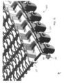
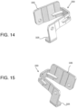
- a further exemplary embodiment which is not part of the invention includes belt 400 which combines the integral hold-down clip 315 with a U-shaped link 330 which also has a vertical extension above the top surface of the belt that serves as an edge guard 335 to retain product on the belt.
- An additional modification of belt 400 could include links with edge guards on every other pitch or every third pitch, etc. instead of every pitch as shown.
- a similar component spacing modification could apply to using links with integral hold-downs.
- the link 330 in FIG. 14 is considered a right-hand link and the link 330 shown in FIG. 15 is considered a left-hand link which is a mirror image of that shown in FIG. 14 and the correct link will be selected depending on which edge of the belt it is to be disposed.
Landscapes
- Engineering & Computer Science (AREA)
- Mechanical Engineering (AREA)
- Textile Engineering (AREA)
- Belt Conveyors (AREA)
Claims (1)
- Une bande transporteuse (100) comprenant :une pluralité de tiges de traction espacées (180) ;une pluralité de rangées de support (160) disposées transversalement par rapport à une direction de déplacement et interconnectant ladite pluralité de tiges de traction espacées (180) ;une pluralité de clips d'entraînement de bande (50) ; etune pluralité de clips de maintien de bande (60) ;dans lequel ladite bande transporteuse (100) comprend des premier et deuxième bords extérieurs opposéset ladite pluralité de clips d'entraînement de bande (50) et/ou de clips de maintien de bande (60) sont disposés sur au moins l'un des premier et deuxième bords extérieurs de la bande transporteuse (100) de telle sorte que lesdits clips d'entraînement de bande (50) et les clips de maintien de bande (60) améliorent la capacité d'entraînement de bord de ladite bande transporteuse (100) ;dans lequel chacune de ladite pluralité de clips de maintien de bande (60) comprend un élément de base ayant au moins une ouverture et un élément vertical (68) disposé sensiblement perpendiculairement audit élément de base, chacune de ladite pluralité de clips de maintien de bande (60) comprenant en outre des parties d'aile opposées (66) s'étendant à partir des côtés opposés dudit élément de base,dans lequel chacune de ladite pluralité de clips d'entraînement de bande (50) est généralement en forme de J avec une première partie de jambe, une seconde partie de jambe et une partie de connexion, les première et seconde parties de jambe définissant deux plans sensiblement parallèles et la partie de connexion définissant un plan coupant les deux plans sensiblement parallèles, chacune de ladite pluralité de clips d'entraînement de bande (50) ayant au moins une ouverture dans la première partie de jambe ou la seconde partie de jambe et aucune ouverture dans la partie de connexion, les ouvertures de chaque clip d'entraînement de bande (50) existant entièrement dans les plans des première et seconde parties de jambe,dans lequel la première partie de jambe a deux ouvertures, la seconde partie de jambe a une ouverture et la partie de connexion relie les première et seconde parties de jambe,caractérisée en ce qu'une pluralité desdites rangées (160) comprennent une liaison en forme de U (170) sur chaque bord et une superposition en forme de maille (190) s'étendant entre elles.
Applications Claiming Priority (1)
| Application Number | Priority Date | Filing Date | Title |
|---|---|---|---|
| US201662394451P | 2016-09-14 | 2016-09-14 |
Publications (3)
| Publication Number | Publication Date |
|---|---|
| EP3330203A1 EP3330203A1 (fr) | 2018-06-06 |
| EP3330203B1 true EP3330203B1 (fr) | 2025-01-22 |
| EP3330203C0 EP3330203C0 (fr) | 2025-01-22 |
Family
ID=59895116
Family Applications (1)
| Application Number | Title | Priority Date | Filing Date |
|---|---|---|---|
| EP17190882.5A Active EP3330203B1 (fr) | 2016-09-14 | 2017-09-13 | Courroie de transporteur à recouvrement maillé et entraînement de bord |
Country Status (3)
| Country | Link |
|---|---|
| US (1) | US10577183B2 (fr) |
| EP (1) | EP3330203B1 (fr) |
| CN (1) | CN107814134A (fr) |
Families Citing this family (7)
| Publication number | Priority date | Publication date | Assignee | Title |
|---|---|---|---|---|
| EP3257793B1 (fr) * | 2016-06-13 | 2020-09-23 | Frans Bakker Beheer B.V. | Courroie de transporteur |
| US10507978B2 (en) | 2017-10-28 | 2019-12-17 | Rabbit Designs LLC | Radius and variable width conveyor belt |
| ZA201904027B (en) * | 2018-06-22 | 2022-04-28 | Dale Holdings Pty Ltd | Positive drive conveyor |
| IT201900006102A1 (it) * | 2019-04-18 | 2020-10-18 | Incobra S R L | Maglia di collegamento per elementi di supporto per nastri trasportatori, elementi di supporto per nastri trasportatori, metodo per la realizzazione della maglia di collegamento e dell’elemento di supporto |
| CN111532663A (zh) * | 2020-05-30 | 2020-08-14 | 金倍励金属(苏州)有限公司 | 一种金属网带链节结构 |
| CN113296142B (zh) * | 2021-05-21 | 2023-01-17 | 山西中辐核仪器有限责任公司 | 传送带式安全帽污染监测仪 |
| US12091256B2 (en) | 2021-09-16 | 2024-09-17 | Cambridge International, Inc. | Material buildup resistant sprocket |
Citations (1)
| Publication number | Priority date | Publication date | Assignee | Title |
|---|---|---|---|---|
| US20130118867A1 (en) * | 2011-10-26 | 2013-05-16 | Cambridge International, Inc. | Conveyor belt with improved edge configuration |
Family Cites Families (15)
| Publication number | Priority date | Publication date | Assignee | Title |
|---|---|---|---|---|
| US3920117A (en) * | 1974-04-23 | 1975-11-18 | Ashworth Bros Inc | Wire conveyor belt |
| FR2503106B1 (fr) * | 1981-04-03 | 1986-04-18 | Frigofrance Sa | Transporteur a bande sans fin decrivant un helicoide |
| US5423416A (en) | 1993-09-03 | 1995-06-13 | Ashworth Brothers, Inc. | Conveyor belts with spiral overlay |
| NL1018669C2 (nl) | 2001-07-31 | 2003-02-03 | Esfo B V | Transportband. |
| ITMI20050149U1 (it) | 2005-04-27 | 2006-10-28 | Tecno Pool Spa | Sistema di sponde laterali di contenimento per il nastro trasportatore di un convogliatore |
| WO2007076532A2 (fr) | 2005-12-29 | 2007-07-05 | Span Tech Llc | Chaine de convoyeur composite a maillons intermediaires denteles |
| ITMI20061395A1 (it) * | 2006-07-18 | 2008-01-19 | Tecno Pool Spa | Nastro trasportatore di un convogliatore a catena con maglie di trascinamento innovative. |
| IT1390848B1 (it) * | 2008-07-31 | 2011-10-19 | Neuroscienze Pharmaness S C A R L | Composti farmaceutici |
| IT1392854B1 (it) * | 2009-02-13 | 2012-03-23 | Tecno Pool Spa | Nastro trasportatore a barre, particolarmente per l'industria alimentare. |
| IT1394088B1 (it) * | 2009-05-08 | 2012-05-25 | Alit S R L | Maglia per catena laterale per nastri trasportatori |
| US8985318B2 (en) * | 2012-05-15 | 2015-03-24 | Ashworth Bros., Inc. | Conveyor belt with composite link |
| ITPD20120267A1 (it) * | 2012-09-14 | 2014-03-15 | Alit S R L | Maglia perfezionata per catena laterale per nastri trasportatori |
| BR112015015279B1 (pt) * | 2012-12-27 | 2021-03-02 | Mayekawa Mfg. Co., Ltd | dispositivo transportador para transportar alimento |
| US9440793B2 (en) * | 2012-12-27 | 2016-09-13 | Mayekawa Mfg. Co., Ltd. | Conveyor device for conveying food |
| ITBO20130650A1 (it) | 2013-11-27 | 2015-05-28 | Millennium Engineering S R L | Convogliatore a catena, in particolare per prodotti alimentari |
-
2017
- 2017-09-12 US US15/702,200 patent/US10577183B2/en active Active
- 2017-09-13 EP EP17190882.5A patent/EP3330203B1/fr active Active
- 2017-09-14 CN CN201710825780.7A patent/CN107814134A/zh active Pending
Patent Citations (1)
| Publication number | Priority date | Publication date | Assignee | Title |
|---|---|---|---|---|
| US20130118867A1 (en) * | 2011-10-26 | 2013-05-16 | Cambridge International, Inc. | Conveyor belt with improved edge configuration |
Also Published As
| Publication number | Publication date |
|---|---|
| US10577183B2 (en) | 2020-03-03 |
| CN107814134A (zh) | 2018-03-20 |
| EP3330203C0 (fr) | 2025-01-22 |
| EP3330203A1 (fr) | 2018-06-06 |
| US20180072504A1 (en) | 2018-03-15 |
Similar Documents
| Publication | Publication Date | Title |
|---|---|---|
| EP3330203B1 (fr) | Courroie de transporteur à recouvrement maillé et entraînement de bord | |
| EP3369681B1 (fr) | Courroie transporteuse à entraînement de bord direct | |
| EP2871144B1 (fr) | Courroies de transport à espacement variable avec des extrémités de tige de sertissage | |
| US9061829B2 (en) | Conveyor belt with improved edge configuration | |
| JP5022357B2 (ja) | 汚泥掻き寄せ装置のチェーン装置 | |
| CN101855151B (zh) | 扁钢丝传送带系统 | |
| EP2220396B1 (fr) | Système et procédé de bande transporteuse à raccord rapide | |
| US5350056A (en) | Self-supporting conveyor belt with wire-formed spacers | |
| US9221611B2 (en) | Variable spaced conveyor belt with shortened edge link cut-off | |
| EP2655224B1 (fr) | Élément de plaque latérale perfectionné pour un maillon compris dans une courroie transporteuse sans fin a auto-empilage | |
| CN104235267B (zh) | 抗后弯链条 | |
| JP6156887B2 (ja) | 複合リンクおよびそれを有するコンベアベルト | |
| US10035681B2 (en) | Belt-driven people conveyor | |
| US12286303B2 (en) | Conveyor belt and device for locking a rod to a link of such a conveyor belt | |
| US6530469B2 (en) | Wire belt with compound link formation | |
| EP0344411B1 (fr) | Transporteur à palettes pour trajet en courbes | |
| US10941834B2 (en) | Splice system for conveyor belt | |
| US10118766B2 (en) | Splice link for conveyor belt | |
| US6796420B2 (en) | Self-stacking conveyor belt and method | |
| US12459743B2 (en) | Weldless conveyor belt systems and methods | |
| DE3844855C2 (en) | Curved conveyor with hinged plates |
Legal Events
| Date | Code | Title | Description |
|---|---|---|---|
| PUAI | Public reference made under article 153(3) epc to a published international application that has entered the european phase |
Free format text: ORIGINAL CODE: 0009012 |
|
| STAA | Information on the status of an ep patent application or granted ep patent |
Free format text: STATUS: THE APPLICATION HAS BEEN PUBLISHED |
|
| AK | Designated contracting states |
Kind code of ref document: A1 Designated state(s): AL AT BE BG CH CY CZ DE DK EE ES FI FR GB GR HR HU IE IS IT LI LT LU LV MC MK MT NL NO PL PT RO RS SE SI SK SM TR |
|
| AX | Request for extension of the european patent |
Extension state: BA ME |
|
| STAA | Information on the status of an ep patent application or granted ep patent |
Free format text: STATUS: REQUEST FOR EXAMINATION WAS MADE |
|
| 17P | Request for examination filed |
Effective date: 20181206 |
|
| RBV | Designated contracting states (corrected) |
Designated state(s): AL AT BE BG CH CY CZ DE DK EE ES FI FR GB GR HR HU IE IS IT LI LT LU LV MC MK MT NL NO PL PT RO RS SE SI SK SM TR |
|
| STAA | Information on the status of an ep patent application or granted ep patent |
Free format text: STATUS: EXAMINATION IS IN PROGRESS |
|
| 17Q | First examination report despatched |
Effective date: 20190821 |
|
| P01 | Opt-out of the competence of the unified patent court (upc) registered |
Effective date: 20240111 |
|
| GRAP | Despatch of communication of intention to grant a patent |
Free format text: ORIGINAL CODE: EPIDOSNIGR1 |
|
| STAA | Information on the status of an ep patent application or granted ep patent |
Free format text: STATUS: GRANT OF PATENT IS INTENDED |
|
| INTG | Intention to grant announced |
Effective date: 20240816 |
|
| GRAS | Grant fee paid |
Free format text: ORIGINAL CODE: EPIDOSNIGR3 |
|
| GRAA | (expected) grant |
Free format text: ORIGINAL CODE: 0009210 |
|
| STAA | Information on the status of an ep patent application or granted ep patent |
Free format text: STATUS: THE PATENT HAS BEEN GRANTED |
|
| AK | Designated contracting states |
Kind code of ref document: B1 Designated state(s): AL AT BE BG CH CY CZ DE DK EE ES FI FR GB GR HR HU IE IS IT LI LT LU LV MC MK MT NL NO PL PT RO RS SE SI SK SM TR |
|
| REG | Reference to a national code |
Ref country code: GB Ref legal event code: FG4D |
|
| REG | Reference to a national code |
Ref country code: CH Ref legal event code: EP |
|
| REG | Reference to a national code |
Ref country code: IE Ref legal event code: FG4D |
|
| REG | Reference to a national code |
Ref country code: DE Ref legal event code: R096 Ref document number: 602017087415 Country of ref document: DE |
|
| U01 | Request for unitary effect filed |
Effective date: 20250219 |
|
| U07 | Unitary effect registered |
Designated state(s): AT BE BG DE DK EE FI FR IT LT LU LV MT NL PT RO SE SI Effective date: 20250225 |
|
| P04 | Withdrawal of opt-out of the competence of the unified patent court (upc) registered |
Free format text: CASE NUMBER: APP_8871/2025 Effective date: 20250221 |
|
| PG25 | Lapsed in a contracting state [announced via postgrant information from national office to epo] |
Ref country code: RS Free format text: LAPSE BECAUSE OF FAILURE TO SUBMIT A TRANSLATION OF THE DESCRIPTION OR TO PAY THE FEE WITHIN THE PRESCRIBED TIME-LIMIT Effective date: 20250422 |
|
| PG25 | Lapsed in a contracting state [announced via postgrant information from national office to epo] |
Ref country code: PL Free format text: LAPSE BECAUSE OF FAILURE TO SUBMIT A TRANSLATION OF THE DESCRIPTION OR TO PAY THE FEE WITHIN THE PRESCRIBED TIME-LIMIT Effective date: 20250122 |
|
| PG25 | Lapsed in a contracting state [announced via postgrant information from national office to epo] |
Ref country code: ES Free format text: LAPSE BECAUSE OF FAILURE TO SUBMIT A TRANSLATION OF THE DESCRIPTION OR TO PAY THE FEE WITHIN THE PRESCRIBED TIME-LIMIT Effective date: 20250122 |
|
| PG25 | Lapsed in a contracting state [announced via postgrant information from national office to epo] |
Ref country code: IS Free format text: LAPSE BECAUSE OF FAILURE TO SUBMIT A TRANSLATION OF THE DESCRIPTION OR TO PAY THE FEE WITHIN THE PRESCRIBED TIME-LIMIT Effective date: 20250522 Ref country code: NO Free format text: LAPSE BECAUSE OF FAILURE TO SUBMIT A TRANSLATION OF THE DESCRIPTION OR TO PAY THE FEE WITHIN THE PRESCRIBED TIME-LIMIT Effective date: 20250422 |
|
| PG25 | Lapsed in a contracting state [announced via postgrant information from national office to epo] |
Ref country code: HR Free format text: LAPSE BECAUSE OF FAILURE TO SUBMIT A TRANSLATION OF THE DESCRIPTION OR TO PAY THE FEE WITHIN THE PRESCRIBED TIME-LIMIT Effective date: 20250122 |
|
| PG25 | Lapsed in a contracting state [announced via postgrant information from national office to epo] |
Ref country code: GR Free format text: LAPSE BECAUSE OF FAILURE TO SUBMIT A TRANSLATION OF THE DESCRIPTION OR TO PAY THE FEE WITHIN THE PRESCRIBED TIME-LIMIT Effective date: 20250423 |
|
| PG25 | Lapsed in a contracting state [announced via postgrant information from national office to epo] |
Ref country code: SM Free format text: LAPSE BECAUSE OF FAILURE TO SUBMIT A TRANSLATION OF THE DESCRIPTION OR TO PAY THE FEE WITHIN THE PRESCRIBED TIME-LIMIT Effective date: 20250122 |
|
| PG25 | Lapsed in a contracting state [announced via postgrant information from national office to epo] |
Ref country code: CZ Free format text: LAPSE BECAUSE OF FAILURE TO SUBMIT A TRANSLATION OF THE DESCRIPTION OR TO PAY THE FEE WITHIN THE PRESCRIBED TIME-LIMIT Effective date: 20250122 |
|
| PG25 | Lapsed in a contracting state [announced via postgrant information from national office to epo] |
Ref country code: SK Free format text: LAPSE BECAUSE OF FAILURE TO SUBMIT A TRANSLATION OF THE DESCRIPTION OR TO PAY THE FEE WITHIN THE PRESCRIBED TIME-LIMIT Effective date: 20250122 |
|
| PLBE | No opposition filed within time limit |
Free format text: ORIGINAL CODE: 0009261 |
|
| STAA | Information on the status of an ep patent application or granted ep patent |
Free format text: STATUS: NO OPPOSITION FILED WITHIN TIME LIMIT |
|
| 26N | No opposition filed |
Effective date: 20251023 |
|
| PGFP | Annual fee paid to national office [announced via postgrant information from national office to epo] |
Ref country code: GB Payment date: 20251229 Year of fee payment: 9 |
|
| U21 | Renewal fee for the european patent with unitary effect paid with additional fee |
Year of fee payment: 9 Effective date: 20251229 |