EP3330407A1 - Dispositif de décapage - Google Patents
Dispositif de décapage Download PDFInfo
- Publication number
- EP3330407A1 EP3330407A1 EP17789025.8A EP17789025A EP3330407A1 EP 3330407 A1 EP3330407 A1 EP 3330407A1 EP 17789025 A EP17789025 A EP 17789025A EP 3330407 A1 EP3330407 A1 EP 3330407A1
- Authority
- EP
- European Patent Office
- Prior art keywords
- pickling
- acid solution
- steel strip
- tank
- pickling tank
- Prior art date
- Legal status (The legal status is an assumption and is not a legal conclusion. Google has not performed a legal analysis and makes no representation as to the accuracy of the status listed.)
- Granted
Links
Images





Classifications
-
- C—CHEMISTRY; METALLURGY
- C23—COATING METALLIC MATERIAL; COATING MATERIAL WITH METALLIC MATERIAL; CHEMICAL SURFACE TREATMENT; DIFFUSION TREATMENT OF METALLIC MATERIAL; COATING BY VACUUM EVAPORATION, BY SPUTTERING, BY ION IMPLANTATION OR BY CHEMICAL VAPOUR DEPOSITION, IN GENERAL; INHIBITING CORROSION OF METALLIC MATERIAL OR INCRUSTATION IN GENERAL
- C23G—CLEANING OR DE-GREASING OF METALLIC MATERIAL BY CHEMICAL METHODS OTHER THAN ELECTROLYSIS
- C23G3/00—Apparatus for cleaning or pickling metallic material
- C23G3/02—Apparatus for cleaning or pickling metallic material for cleaning wires, strips, filaments continuously
- C23G3/021—Apparatus for cleaning or pickling metallic material for cleaning wires, strips, filaments continuously by dipping
-
- C—CHEMISTRY; METALLURGY
- C23—COATING METALLIC MATERIAL; COATING MATERIAL WITH METALLIC MATERIAL; CHEMICAL SURFACE TREATMENT; DIFFUSION TREATMENT OF METALLIC MATERIAL; COATING BY VACUUM EVAPORATION, BY SPUTTERING, BY ION IMPLANTATION OR BY CHEMICAL VAPOUR DEPOSITION, IN GENERAL; INHIBITING CORROSION OF METALLIC MATERIAL OR INCRUSTATION IN GENERAL
- C23G—CLEANING OR DE-GREASING OF METALLIC MATERIAL BY CHEMICAL METHODS OTHER THAN ELECTROLYSIS
- C23G3/00—Apparatus for cleaning or pickling metallic material
- C23G3/02—Apparatus for cleaning or pickling metallic material for cleaning wires, strips, filaments continuously
- C23G3/025—Details of the apparatus, e.g. linings or sealing means
-
- B—PERFORMING OPERATIONS; TRANSPORTING
- B08—CLEANING
- B08B—CLEANING IN GENERAL; PREVENTION OF FOULING IN GENERAL
- B08B3/00—Cleaning by methods involving the use or presence of liquid or steam
- B08B3/04—Cleaning involving contact with liquid
- B08B3/041—Cleaning travelling work
-
- B—PERFORMING OPERATIONS; TRANSPORTING
- B08—CLEANING
- B08B—CLEANING IN GENERAL; PREVENTION OF FOULING IN GENERAL
- B08B3/00—Cleaning by methods involving the use or presence of liquid or steam
- B08B3/04—Cleaning involving contact with liquid
- B08B3/08—Cleaning involving contact with liquid the liquid having chemical or dissolving effect
-
- B—PERFORMING OPERATIONS; TRANSPORTING
- B08—CLEANING
- B08B—CLEANING IN GENERAL; PREVENTION OF FOULING IN GENERAL
- B08B3/00—Cleaning by methods involving the use or presence of liquid or steam
- B08B3/04—Cleaning involving contact with liquid
- B08B3/10—Cleaning involving contact with liquid with additional treatment of the liquid or of the object being cleaned, e.g. by heat, by electricity or by vibration
-
- C—CHEMISTRY; METALLURGY
- C23—COATING METALLIC MATERIAL; COATING MATERIAL WITH METALLIC MATERIAL; CHEMICAL SURFACE TREATMENT; DIFFUSION TREATMENT OF METALLIC MATERIAL; COATING BY VACUUM EVAPORATION, BY SPUTTERING, BY ION IMPLANTATION OR BY CHEMICAL VAPOUR DEPOSITION, IN GENERAL; INHIBITING CORROSION OF METALLIC MATERIAL OR INCRUSTATION IN GENERAL
- C23G—CLEANING OR DE-GREASING OF METALLIC MATERIAL BY CHEMICAL METHODS OTHER THAN ELECTROLYSIS
- C23G1/00—Cleaning or pickling metallic material with solutions or molten salts
- C23G1/02—Cleaning or pickling metallic material with solutions or molten salts with acid solutions
- C23G1/08—Iron or steel
-
- C—CHEMISTRY; METALLURGY
- C23—COATING METALLIC MATERIAL; COATING MATERIAL WITH METALLIC MATERIAL; CHEMICAL SURFACE TREATMENT; DIFFUSION TREATMENT OF METALLIC MATERIAL; COATING BY VACUUM EVAPORATION, BY SPUTTERING, BY ION IMPLANTATION OR BY CHEMICAL VAPOUR DEPOSITION, IN GENERAL; INHIBITING CORROSION OF METALLIC MATERIAL OR INCRUSTATION IN GENERAL
- C23G—CLEANING OR DE-GREASING OF METALLIC MATERIAL BY CHEMICAL METHODS OTHER THAN ELECTROLYSIS
- C23G1/00—Cleaning or pickling metallic material with solutions or molten salts
- C23G1/02—Cleaning or pickling metallic material with solutions or molten salts with acid solutions
- C23G1/08—Iron or steel
- C23G1/081—Iron or steel solutions containing H2SO4
-
- C—CHEMISTRY; METALLURGY
- C23—COATING METALLIC MATERIAL; COATING MATERIAL WITH METALLIC MATERIAL; CHEMICAL SURFACE TREATMENT; DIFFUSION TREATMENT OF METALLIC MATERIAL; COATING BY VACUUM EVAPORATION, BY SPUTTERING, BY ION IMPLANTATION OR BY CHEMICAL VAPOUR DEPOSITION, IN GENERAL; INHIBITING CORROSION OF METALLIC MATERIAL OR INCRUSTATION IN GENERAL
- C23G—CLEANING OR DE-GREASING OF METALLIC MATERIAL BY CHEMICAL METHODS OTHER THAN ELECTROLYSIS
- C23G3/00—Apparatus for cleaning or pickling metallic material
- C23G3/02—Apparatus for cleaning or pickling metallic material for cleaning wires, strips, filaments continuously
- C23G3/025—Details of the apparatus, e.g. linings or sealing means
- C23G3/026—Details of the apparatus, e.g. linings or sealing means for guiding the objects
-
- C—CHEMISTRY; METALLURGY
- C23—COATING METALLIC MATERIAL; COATING MATERIAL WITH METALLIC MATERIAL; CHEMICAL SURFACE TREATMENT; DIFFUSION TREATMENT OF METALLIC MATERIAL; COATING BY VACUUM EVAPORATION, BY SPUTTERING, BY ION IMPLANTATION OR BY CHEMICAL VAPOUR DEPOSITION, IN GENERAL; INHIBITING CORROSION OF METALLIC MATERIAL OR INCRUSTATION IN GENERAL
- C23G—CLEANING OR DE-GREASING OF METALLIC MATERIAL BY CHEMICAL METHODS OTHER THAN ELECTROLYSIS
- C23G3/00—Apparatus for cleaning or pickling metallic material
- C23G3/02—Apparatus for cleaning or pickling metallic material for cleaning wires, strips, filaments continuously
- C23G3/027—Associated apparatus, e.g. for pretreating or after-treating
-
- B—PERFORMING OPERATIONS; TRANSPORTING
- B08—CLEANING
- B08B—CLEANING IN GENERAL; PREVENTION OF FOULING IN GENERAL
- B08B2203/00—Details of cleaning machines or methods involving the use or presence of liquid or steam
- B08B2203/007—Heating the liquid
Definitions
- the present invention relates to a pickling device.
- a pickling device is a device for cleaning and removing oxidized scales, which are oxidized matter formed on a surface of a steel strip such as a cold-rolled steel plate and a hot-rolled steel plate, by causing the oxidized scales to react with acid solution such as hydrochloric acid and sulfuric acid.
- acid solution such as hydrochloric acid and sulfuric acid.
- Patent Document 1 discloses a pickling device including: a pickling tank filled with acid solution; a lid covering an upper part of the pickling tank; an immersion guide roll disposed rotatably on the lower surface of the lid; a support block disposed on the bottom surface of the pickling tank; a bottom plate disposed on an upper part of the support block; and a skid disposed on the upper surface of the bottom plate to face the immersion guide roll, wherein the pickling device performs pickling of a steel strip by causing the steel strip to travel through the acid solution while guiding the steel strip with the immersion guide roll and the skid.
- Patent Document 1 JP3160300B
- travel of a steel strip may be stopped temporarily (e.g. from a couple of hours to one day), for maintenance or the like of a device disposed upstream or downstream of the pickling device with respect to the traveling direction of the steel strip.
- pickling of the steel strip advances to cause over-pickling.
- the total volume of the acid solution in the pickling tank is transferred to a sub tank provided separately from the pickling tank, or the steel strip is lifted above the acid solution.
- the acid solution inside the pickling tank may be transferred to the sub tank so that the upper limit liquid level of the acid solution in the pickling tank becomes lower than the traveling height of the steel strip.
- An object of the present invention is to provide a pickling device capable of preventing over-pickling of a steel strip during pickling pause and reducing the switching time between pickling operation and pickling pause, as well as efficiently heating the acid solution with a heat exchanger disposed inside the pickling tank, even during pickling pause.
- a pickling device for solving the above problem includes: a pickling tank for storing acid solution and for pickling a steel strip by allowing the steel strip to travel therethrough while the steel strip is immersed in the acid solution; a heating unit for heating the acid solution in the pickling tank; an acid-solution storage tank for storing the acid solution, provided separately from the pickling tank; an acid-solution circulation unit configured to circulate the acid solution between the pickling tank and the acid-solution storage tank; a withdrawing unit configured to withdraw the steel strip from the acid solution; and a guide plate disposed in the pickling tank and configured to guide the acid solution circulated in the pickling tank by the acid-solution circulation unit to the heating unit.
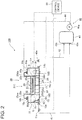
- a pickling device 100 includes a pickling tank 10, a circulation tank (acid-solution storage tank) 43, an acid-solution circulation device (acid-solution circulation unit) 40, and a control device (withdrawing unit) 50.
- the pickling tank 10 is a deep tank.
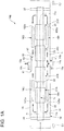
- the pickling tank 10 includes: a tank body having a bottom plate 11, a front plate 12, a rear plate 13, a right plate 14, and a left plate 15, which is open at the top, and is capable of storing acid solution L; and a plurality of (four in the illustrated example) cover members 25 covering the opening of the tank body.
- the bottom plate 11 extends in the traveling direction of a steel strip S, and is inclined such that the bottom plate 11 reaches its lowermost point at the first drain port 15b (central circulation port) described below in detail.
- the front plate 12, the rear plate 13, the right plate 14, and the left plate 15 form vertical walls of the pickling tank 10. It is sufficient if the pickling tank 10 is made of an acid-resistant material.
- the pickling tank 10 may be made of a resin such as polypropylene, or a resin-based composite material.
- the front plate 12 is connected to a front end portion of the bottom plate 11, disposed on the upstream side with respect to the traveling direction of the steel strip S.
- the rear plate 13 is connected to a rear end portion of the bottom plate 11, disposed on the downstream side with respect to the traveling direction of the steel strip S.
- the right plate 14 is connected to the right end portion of the bottom plate 11 with respect to the width direction, entirely in the traveling direction of the steel strip S.
- the upstream end portion and the downstream end portion of the right plate 14, with respect to the traveling direction of the steel strip S are connected to the front plate 12 and the rear plate 13.
- the left plate 15 is connected to the left end portion of the bottom plate 11 with respect to the width direction, entirely in the traveling direction of the steel strip S.
- the upstream end portion and the downstream end portion of the left plate 15, with respect to the traveling direction of the steel strip S are connected to the front plate 12 and the rear plate 13.
- the left plate 15 has a first drain port (drain port for the acid solution) 15b disposed thereon.
- the right plate 14 has a second drain port 14b and a supply port 14c (supply port for the acid solution) disposed thereon.
- the right plate 14 and the left plate 15 are provided with fixed brackets 19a, 19b, at the center portion with respect to the traveling direction of the steel strip S.
- the pickling tank 10 is fixedly positioned on a mount or a base at the fixed brackets 19a, 19b.
- the pickling tank 10 has a high thermal expansion coefficient if made of a resin-based material such as polypropylene.
- the first drain port (drain port for the acid solution), the second drain port 14b, and the supply port 14c (supply port for the acid solution) disposed on the center portion at which the pickling tank 10 is fixedly positioned are less affected by thermal expansion, which is preferable.
- a front flange portion 12a is formed so as to extend horizontally upstream in the traveling direction of the steel strip S.
- a rear flange portion 13a is formed so as to extend horizontally downstream in the traveling direction of the steel strip S.
- An inlet skid 31 is disposed on the front flange portion 12a, and an outlet skid 32 is disposed on the rear flange portion 13a.
- a right flange portion 14a and a left flange portion 15a are formed, respectively, so as to extend inward in the width direction of the pickling tank 10.
- a right receiving portion 16a is disposed on the right flange portion 14a
- a left receiving portion 16b is disposed on the left flange portion 15a.
- the right receiving portion 16a and the left receiving portion 16b are both filled with seal solution, such that end portions of the right plates 25d and the left plates 25e of the cover members 25 are immersed in the seal solution. Accordingly, the upper sides of both end portions of the pickling tank 10, with respect to the width direction, are sealed with the cover members 25.
- a plurality of (three in the illustrated example) width-directional receiving portions 17 are disposed to connect the right plate 14 and the left plate 15 so as to form a shape that extends in the width direction of the pickling tank 10.
- the plurality of width-directional receiving portions 17 are arranged next to one another in the traveling direction of the steel strip S.
- the plurality of width-directional receiving portions 17 are disposed between guide device bodies (described below) arranged next to one another in the traveling direction of the steel strip S.
- the width-directional receiving portions 17 are filled with seal solution, such that end portions of the front plates 25b and the rear plates 25c of the cover members 25 are immersed in the seal solution. Accordingly, the upper sides between the guide device bodies, arranged next to one another with respect to the traveling direction of the steel strip S in the pickling tank 10, are sealed with the cover members 25.
- a plurality of (four in the illustrated example) heat exchangers (heating units) 18A to 18D are disposed inside the pickling tank 10.
- the first and second heat exchangers 18A, 18B are arranged next to one another in the traveling direction of the steel strip S.
- the third and fourth heat exchangers 18C, 18D are arranged next to one another in the traveling direction of the steel strip S.
- the first and second heat exchangers 18A, 18B are disposed on the bottom plate 11, under the right flange portion 14a and adjacent to the right plate 14 of the pickling tank 10. That is, the first and second heat exchangers 18A, 18B are arranged along the right plate 14 of the pickling tank 10.
- the third and fourth heat exchangers 18C, 18D are disposed on the bottom plate 11, under the left flange portion 15a and adjacent to the left plate 15. That is, the third and fourth heat exchangers 18C, 18D are disposed on the bottom plate 11, along the left plate 15 of the pickling tank 10.
- the first heat exchanger 18A and the third heat exchanger 18C are disposed plane-symmetrically with respect to the center of the pickling tank 10 with respect to the width direction of the pickling tank 10.
- the second heat exchanger 18B and the fourth heat exchanger 18D are disposed plane-symmetrically with respect to the center of the pickling tank 10 with respect to width direction of the pickling tank 10.
- the heat exchangers 18A to 18D are substantially flush with the traveling height h of the steel strip S in the pickling tank 10.
- the heat exchangers 18A to 18D are each a heat-transfer tube which is arranged to extend in the height direction and the side-plate width direction, and which has a function of indirect heating through supply of a heat medium (e.g. steam) into the tube.
- a heat medium e.g. steam
- the pickling tank 10 includes a guide device (steel strip guide device) 20 for guiding the steel strip S.
- the guide device 20 includes a plurality of (four in the illustrated example) guide device bodies 21A to 21D.
- the plurality of guide device bodies 21A to 21D are arranged next to one another in the traveling direction of the steel strip S.
- the guide device bodies 21A to 21 D each includes a gutter-shaped member (immersion box) 22 having a U-shaped lateral cross section, an immersion guide roll 23, a skid 24, and a support block 26.
- the gutter-shaped member 22 has a shape that extends in the traveling direction of the steel strip S and has openings on the upstream side and the downstream side with respect to the traveling direction of the steel strip S.
- the gutter-shaped member 22 has a bottom plate portion 22a, a right plate portion 22c, and a left plate portion 22d.
- the right plate portion 22c and the left plate portion 22d are disposed so as to face each other.
- An end portion of the bottom plate portion 22a (an end portion with respect to the width direction of the steel strip S) and the other end portion of the bottom plate portion 22a (the other end portion with respect to the width direction of the steel strip S) are connected to the right plate portion 22c and the left plate portion 22d entirely in the traveling direction of the steel strip S.
- the gutter-shaped member 22 is supported by the support block 26.
- the skid 24 is disposed on the front end portion side of the bottom plate portion 22a, which forms an upstream end portion with respect to the traveling direction of the steel strip S.
- the skid 24 is also disposed on the rear end portion side of the bottom plate portion 22a, which forms a downstream end portion with respect to the traveling direction of the steel strip S.
- An immersion guide roll 23 is disposed on the front end portion side of a cover member body 25a described below in detail, which forms an upstream end portion with respect to the traveling direction of the steel strip S.
- the support block 26 is disposed below the skid 24, on the front end portion side of the bottom plate portion 22a, which forms an upstream end portion with respect to the traveling direction of the steel strip S.
- the support block 26 is disposed on each of both end portions with respect to the width direction of the steel strip S.
- the guide device bodies 21A to 21 D are arranged at a predetermined height inside the pickling tank 10.
- the pickling tank 10 is filled with acid solution L to the substantially same height as the guide device bodies 21A to 21 D, and the steel strip S is guided while being immersed in the acid solution L (at a predetermined traveling height h).
- the cover member 25 includes a cover member body 25a, a front plate 25b, a rear plate 25c, a right plate 25d, and a left plate 25e.
- the cover member body 25a has a plate shape.
- the cover member body 25a is disposed above the gutter-shaped member 22.
- the front plate 25b has a shape that connects to the front end portion of the cover member body 25a, and extends upward.
- a front flange portion 25ba is formed so as to extend upstream in the traveling direction of the steel strip S.
- a tip end portion of the front flange portion 25ba of the front plate 25b is bended downward and immersed in seal solution stored in the width-directional receiving portion 17.
- the rear plate 25c has a shape that connects to the rear end portion of the cover member body 25a, and extends upward. On the upper end portion of the rear plate 25c, a rear flange portion 25ca is formed so as to extend downstream in the traveling direction of the steel strip S. With regard to the cover member 25 arranged corresponding to each of the first to third guide device bodies 21A to 21C, a tip end portion of the rear flange portion 25ba of the rear plate 25c is bended downward and immersed in the seal solution stored in the width-directional receiving portion 17.
- the right plate 25d has a shape that connects to the right end portion of the cover member body 25a, and extends upward.
- a right flange portion 25da is formed so as to extend outward in the width direction of the steel strip S.
- a tip end portion of the right flange portion 25da is bended downward and immersed in the seal solution stored in the right receiving portion 16a.
- the left plate 25e has a shape that connects to the left end portion of the cover member body 25a, and extends upward.
- a left flange portion 25ea is formed so as to extend outward in the width direction of the steel strip S.
- a tip end portion of the left flange portion 25ea is bended downward and immersed in the seal solution stored in the left receiving portion 16b.
- cover members 25 provided corresponding to the first to fourth guide device bodies 21Ato 21D cover the pickling tank 10 from above.
- the acid-solution circulation device 40 includes a first drain pipe 41, a second drain pipe 42, and a supply pipe (return pipe) 44.
- the first drain pipe 41 has a root end side (an end portion side) connected to the first drain port 15b of the pickling tank 10, and a distal end side (the other portion side) connected to the circulation tank 43.
- An opening-and-closing valve 41a is disposed in the first drain pipe 41.
- the second drain pipe 42 has a root end side connected to the second drain port 14b of the pickling tank 10, and a distal end side (the other end portion side) connected to the circulation tank 43.
- An opening-and-closing valve 42a is disposed in the second drain pipe 42.
- the supply pipe 44 has a root end side (an end portion side) connected to the circulation tank 43, and a distal end side (the other end portion side) connected to the supply port 14c of the pickling tank 10.
- a circulation pump 44a is disposed in the supply pipe 44.
- the first supply port 43a of the circulation tank 43 connected to the distal end side of the first drain pipe 41 is positioned below the upper end portion 60a of a dam 60 disposed inside the pickling tank 10. In this way, it is possible to discharge the acid solution L above the dam 60 from the pickling tank 10 efficiently.
- the second supply port 43b of the circulation tank 43 connected to the distal end side of the second drain pipe 42 is positioned below the bottom plate 11 of the pickling tank 10. In this way, it is possible to discharge the total volume of the acid solution L in the pickling tank 10 from the pickling tank 10 efficiently.
- the pickling device 100 further includes a dam 60 disposed inside the pickling tank 10.
- the dam 60 has a shape that surrounds the first drain port 15b, and includes a front plate portion 61, a rear plate portion 62, and a side plate portion 63.
- the front plate portion 61 of the dam 60 has a shape that connects to the left plate 15 and the bottom plate 11 and extends in the width direction of the pickling tank 10.
- the rear plate portion 62 of the dam 60 is connected to the left plate 15 and the bottom plate 11.
- the rear plate portion 62 of the dam 60 is disposed at a distance from the front plate portion 61, and has a shape that extends parallel to the front plate portion 61.
- the side plate portion 63 of the dam 60 has a shape that connects to an end portion of the front plate portion 61, an end portion of the rear plate portion 62, and the bottom plate 11, and extends in the traveling direction of the steel strip S.
- the upper end portion (inlet) 60a of the dam 60 is preferably disposed in a range below the traveling height h of the steel strip S inside the pickling tank 10, and above the 1/3 height of the liquid level La of the acid solution L during pickling operation. More preferably, the upper end portion 60a of the dam 60 is disposed in a range below the bottom plate portion 22a of the gutter-shaped member 22 and above the 1/2 height of the liquid level La of the acid solution L during pickling operation.
- the dam 60 forms an inflow passage connecting to the first drain port 15b, and forms a part of a withdrawing unit configured to withdraw the steel strip S from the acid solution L by allowing the acid solution L to flow over the upper end portion 60a to adjust the liquid level Lb of the acid solution L to be below the traveling height h of the steel strip S.
- the inflow passage may be disposed outside the pickling tank 10, with the inlet connected to the side plate 15 of the pickling tank 10.
- the dam 60 and the pickling tank 10 are made of the same material.
- the dam 60 may be preferably made of the same resin as the pickling tank 10. In this way, the dam 60 can expand thermally along with the pickling tank 10, which holds the acid solution L having a high temperature (e.g. 85 to 90 °C) during pickling operation and pickling pause. If the pickling tank 10 and the dam 60 are made of different materials, there is an increased risk of breakage occurring due to difference in the thermal expansion at joints between the pickling tank 10 and the dam 60.
- the above described pickling device 100 further includes a guide plate (acid-solution guide plate) 71 disposed inside the pickling tank 10.
- the guide plate 71 has a shape which extends along the traveling direction of the steel strip S.
- the guide plate 71 has the substantially same height as the bottom plate portion 22a of the gutter-shaped member 22 of the guide device 20 disposed in the pickling tank 10.
- the upper end portion 71a of the guide plate 71 is positioned directly below the bottom plate portion 22a of the gutter-shaped member 22 of the guide device 20.
- the lower end portion 71d of the guide plate 71 is fixed to the bottom plate 11 of the pickling tank 10.
- the guide plate 71 is disposed between the first drain port 15b and the supply port 14c in the pickling tank 10. In this way, it is possible to guide the acid solution L to the heat exchangers 18A to 18D and heat the entire acid solution L efficiently, as compared to a case in which the acid solution L flows linearly from the supply port 14c to the first drain port 15b. Furthermore, preferably, the guide plate 71 is disposed between the first and second heat exchangers 18A, 18B arranged along the right plate (a side plate) 14, and between the third and fourth heat exchangers 18C, 18D arranged along the left plate (the other side plate) 15.
- the guide plate 71 is disposed in the center of the pickling tank 10 with respect to the width direction. In this way, it is possible to heat the acid solution with a good balance between the first and second heat exchangers 18A, 18B arranged along the right plate 14, and the third and fourth heat exchangers 18C, 18D arranged along the left plate 15.
- the guide plate 71 has a shape which extends upstream, with respect to the traveling direction of the steel strip S, from the front end portions 18Aa, 18Ca of the first and third heat exchangers 18A, 18C disposed most upstream with respect to the traveling direction of the steel strip S, and which extends downstream, with respect to the traveling direction of the steel strip S, from the rear end portions 18Bb, 18Db of the second and fourth heat exchangers 18B, 18D disposed most downstream with respect to the traveling direction of the steel strip S.
- the front end portion 71b of the guide plate 71 is positioned on the upstream side of the first and third heat exchangers 18A, 18C, with respect to the traveling direction of the steel strip S.
- the rear end portion 71c of the guide plate 71 is positioned on the downstream side of the second and fourth heat exchangers 18B, 18D, with respect to the traveling direction of the steel strip S. Accordingly, in a range where the first to fourth heat exchangers 18A to 18D are arranged in the traveling direction of the steel strip S, the region on the side of the right plate 14 of the pickling tank 10 and the region on the side of the left plate 15 of the pickling tank 10 are divided in the width direction of the steel strip S.
- the acid solution L can flow between the regions on the side of the right plate 14 and the side of the left plate 15 of the pickling tank 10.
- the guide plate 71 is made of an acid-resistant material.
- the pickling tank 10 may be made of a resin such as polypropylene, or a resin-based composite material.
- the region is divided into the side of the heat exchangers 18A, 18C disposed adjacent to the right plate 14 of the pickling tank 10, and the side of the heat exchangers 18B, 18D disposed adjacent to the left plate 15 of the pickling tank 10.
- the control device 50 is a device for controlling each component of the pickling device 100.
- the output side of the control device 50 is connected to the heat exchangers 18A to 18D, the opening-and-closing valves 41a, 42a, and the circulation pump 44a, and is configured to be capable of controlling these components.
- the control device 50 controls the heat exchangers 18A to 18D so as to heat the acid solution L to a predetermined temperature (e.g. 85 to 90 °C), and controls the acid-solution circulation device 40 such that the acid solution L does not circulate.
- the control device 50 controls the opening-and-closing valves 41a, 42a disposed in the first and second drain pipes 41, 42 to be fully closed, and controls the circulation pump 44a to stop. Accordingly, inside the pickling tank 10, the acid solution L is heated to the predetermined temperature, and the liquid level La of the acid solution L is maintained at the substantially same level as the cover member bodies 25a of the cover members 25.
- the steel strip S undergoes the pickling process, by traveling through the acid solution L while being immersed in the acid solution L, guided by the immersion guide rolls 23 and the skids 24.
- the control device 50 controls the heat exchangers 18A to 18D so as to heat the acid solution L to a predetermined temperature (e.g. 85 to 90 °C), and controls the acid-solution circulation device 40 so as to circulate the acid solution L.
- a predetermined temperature e.g. 85 to 90 °C
- the control device 50 controls the opening-and-closing valve 42a disposed in the second drain pipe 42 to be fully closed, and controls the opening-and-closing valve 41a disposed in the first drain pipe 41 to be fully open.
- the acid solution L inside the pickling tank 10 flows over the upper end portion 60a of the dam 60 toward the vicinity of the first drain port 15b, and then flows from the first drain port 15b through the first drain pipe 41 into the circulation tank 43, where the acid solution L is temporarily stored. Furthermore, the acid solution L inside the pickling tank 10 is discharged into the circulation tank 43 via the first drain pipe 41, such that the liquid level Lb of the acid solution L inside the pickling tank 10 becomes substantially flush with the upper end portion 60a of the dam 60. Then, the control device 50 controls the opening degree of the opening-and-closing valve 41a, and controls the circulation pump 44a to operate.
- the acid solution L stored temporarily inside the circulation tank 43 flows into the pickling tank 10 via the supply pipe 44 in response to operation of the circulation pump 44a. That is, the first drain pipe 41 and the supply pipe 44 form two flow passages through which the acid solution L flows between the pickling tank 10 and the circulation tank 43. Whether the acid solution L is substantially flush with the upper end portion 60a of the dam 60 may be determined on the basis of a signal from a liquid level sensor provided in advance, or on the basis of elapse of time that the acid solution L takes to reach the upper end portion 60a of the dam 60, the time being obtained in advance.
- the liquid level Lb of the acid solution L can be maintained at the same level as the upper end portion 60a of the dam 60. Furthermore, the position below the upper end portion 60a of the dam 60 may be used as a criteria for determining whether to supply the acid solution L from the circulation tank 43 to the pickling tank 10.
- the acid solution L flows along the right plate 14 (a side wall) of the pickling tank 10 toward each of the upstream side and the downstream side with respect to the traveling direction of the steel strip S.
- the acid solution L flows between the front end portion 71b of the guide plate 71 and the front plate 12 of the pickling tank 10, and between the rear end portion 71c of the guide plate 71 and the rear plate 13 of the pickling tank 10, respectively, toward the left plate (the other side wall) 15 of the pickling tank 10.
- the acid solution L flows along the left plate 15 toward the first drain port 15b via the dam 60 in the center with respect to the traveling direction of the steel strip S.
- the liquid level Lb of the acid solution L inside the pickling tank 10 is lowered to the substantially same level as the upper end portion 60a of the dam 60, which is below the traveling height h of the steel strip S inside the pickling tank 10.
- the acid solution L is circulated by the acid-solution circulation device 40 between the pickling tank 10 and the circulation tank 43, and the circulating acid solution L is guided by the guide plate 71 to the heat exchangers 18A to 18D through a predetermined flow path. Accordingly, the acid solution L is heated to the predetermined temperature by the heat exchangers 18A to 18D inside the pickling tank 10.
- the acid solution L circulates between the pickling tank 10 and the circulation tank 43 while the liquid level of the acid solution L inside the pickling tank 10 is adjusted to be below the traveling height h of the steel strip S so that the steel strip S is withdrawn from the acid solution L, and thereby it is possible to prevent over-pickling of the steel strip S. Furthermore, the acid solution L is circulated between the pickling tank 10 and the circulation tank 43 by the acid-solution circulation device, the guide plate 71 guides the acid solution L to the heat exchangers 18A to 18D, and the heat exchangers 18A to 18D heat the acid solution L to a predetermined temperature.
- the control device 50 is configured to control opening and closing of the opening-and-closing valve 41a and operation of the circulation pump 44a to adjust the liquid level Lb of the acid solution L in the pickling tank 10 to be below the traveling height h of the steel strip S, so as to withdraw the steel strip S from the acid solution L. Therefore, even though the configuration is simple, the control device 50 can prevent over-pickling of the steel strip S during pickling pause reliably, and to shorten the time required to switch between pickling operation and pickling pause, heating the acid solution L efficiently.
- the pickling tank 10 has a depth such that the upper edge of each heat exchanger 18A to 18D is arranged in the acid solution L at the substantially same level as the traveling height h of the steel strip S, and the pickling tank 10 is provided with the guide device 20 for guiding the steel strip S to travel at a predetermined height in the acid solution L when the steel strip S is pickled with the acid solution L in the pickling tank 10.
- the present embodiment has a configuration in which the acid-solution circulation device and the control device provided for the above described first embodiment shown in FIGs. 1A , 1B , and 2 are modified.
- the other configuration is similar to that of the above described device shown in FIGs. 1A , 1B , and 2 , and the same feature is indicated by the same reference numeral and not described again in detail.
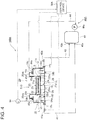
- a pickling device 100A includes the same devices as the acid device 100 according to the above described first embodiment, as well as an acid-solution circulation device (acid-solution circulation unit) 40A, a liquid level sensor (liquid level measurement unit) 64, and a control device (withdrawing unit) 50A.
- the acid-solution circulation device 40A includes a first drain pipe 41, an opening-and-closing valve 41a, a supply pipe 44, and a circulation pump 44a.
- the opening degree of the opening-and-closing valve 41a is controlled, and the timing for driving the circulation pump 44a is also controlled. Accordingly, the acid solution L inside the pickling tank 10 is fed into the pickling tank 10 via the first drain pipe 41, the circulation tank 43, and the supply pipe 44, and inside the pickling tank 10, the liquid level Lb of the acid solution L is maintained at a predetermined level, below the traveling height h of the steel strip S.
- the liquid level sensor 64 is a device for detecting the liquid level of the acid solution L inside the pickling tank 10.
- the tip end portion 64a of the liquid level sensor 64 is positioned below the gutter-shaped member 22 of the guide device 20.
- the output side of the liquid level sensor 64 is connected to the control device 50A, and the liquid level sensor 64 detects the liquid level of the acid solution L inside the pickling tank 10 and sends information related to the liquid level of the acid solution L to the control device 50A.
- the input side of the control device 50A is connected to the liquid level sensor 64.
- the output side of the control device 50A is connected to the heat exchangers 18A to 18D, the opening-and-closing valve 41a, and the circulation pump 44a.
- the control device 50A controls the heat exchangers 18A to 18D so as to heat the acid solution L to a predetermined temperature (e.g. 85 to 90 °C), and controls the acid-solution circulation device 40A so as not to circulate the acid solution L.
- the control device 50A controls the opening-and-closing valves 41a, 42a disposed in the first and second drain pipes 41, 42 to be fully closed, and controls the circulation pump 44a to stop.
- the acid solution L is heated to the predetermined temperature, and the liquid level La of the acid solution L is maintained at the substantially same level as the cover member bodies 25a of the cover members 25.
- the steel strip S undergoes the pickling process, by traveling through the acid solution L while being immersed in the acid solution L, guided by the immersion guide rolls 23 and the skids 24.
- the control device 50A controls the heat exchangers 18A to 18D so as to heat the acid solution L to a predetermined temperature (e.g. 85 to 90 °C), and controls the acid-solution circulation device 40A so as to circulate the acid solution L.
- the control device 50A controls the opening-and-closing valve 42a disposed in the second drain pipe 42 to be fully closed, and controls the opening-and-closing valve 41a disposed in the first drain pipe 41 to be fully open.
- the acid solution L inside the pickling tank 10 flows from the first drain port 15b through the first drain pipe 41 into the circulation tank 43, in which the acid solution L is temporarily stored. Then, when the height of the liquid level Lb of the acid solution L inside the pickling tank 10 detected by the liquid level sensor 64 is below the guide device bodies 21A to 21D, the control device 50A controls the opening degree of the opening-and-closing valve 41a, and controls the circulation pump 44a to operate. Accordingly, the acid solution L stored temporarily inside the circulation tank 43 flows into the pickling tank 10 via the supply pipe 44 in response to operation of the circulation pump 44a.
- the acid solution L flows along the right plate 14 (a side wall) of the pickling tank 10 toward each of the upstream side and the downstream side with respect to the traveling direction of the steel strip S.
- the acid solution L flows between the front end portion 71b of the guide plate 71 and the front plate 12 of the pickling tank 10, and between the rear end portion 71c of the guide plate 71 and the rear plate 13 of the pickling tank 10, respectively, toward the left plate (the other side wall) 15 of the pickling tank 10.
- the acid solution flows along the left plate 15 toward the first drain port 15b in the center with respect to the traveling direction of the steel strip S.
- the liquid level Lb of the acid solution L inside the pickling tank 10 is lowered to a level below the traveling height h of the steel strip S inside the pickling tank 10, and in this state, the acid solution L is circulated by the acid-solution circulation device 40A between the pickling tank 10 and the circulation tank 43, and the circulating acid solution L is guided by the guide plate 71 to the heat exchangers 18A to 18D through a predetermined flow path. Accordingly, the acid solution L is heated to the predetermined temperature by the heat exchangers 18A to 18D inside the pickling tank 10.
- the acid solution L circulates between the pickling tank 10 and the circulation tank 43 while the liquid level of the acid solution L inside the pickling tank 10 is adjusted to be below the traveling height h of the steel strip S so that the steel strip S is withdrawn from the acid solution L, and thereby it is possible to prevent over-pickling of the steel strip S. Furthermore, the acid solution L is circulated between the pickling tank 10 and the circulation tank 43 by the acid-solution circulation device 40A, and the guide plate 71 guides the acid solution L to the heat exchangers 18A to 18D, so that the heat exchangers 18A to 18D heat the acid solution L to a predetermined temperature.
- the control device 50A is configured to control opening and closing of the opening-and-closing valve 41a and operation of the circulation pump 44a to adjust the liquid level Lb of the acid solution L in the pickling tank 10 to be below the traveling height h of the steel strip S, so as to withdraw the steel strip S from the acid solution L. Therefore, even though the configuration is simple, the control device 50 can prevent over-pickling of the steel strip S during pickling pause reliably, and to shorten the time required to switch between pickling operation and pickling pause.
- the control device 50A is configured to control opening and closing of the opening-and-closing valve 41a and operation of the circulation pump 44a on the basis of the liquid level of the acid solution L measured by the liquid level sensor 64.
- the liquid level Lb of the acid solution L in the pickling tank 10 is adjusted to be below the traveling height h of the steel strip S, so as to withdraw the steel strip S from the acid solution L. Therefore, even though the configuration is simple, the control device 50 can prevent over-pickling of the steel strip S during pickling pause even more reliably, shorten the time required to switch between pickling operation and pickling pause, and heat the acid solution efficiently.
- the present embodiment has a configuration in which the guide device, the cover member, the guide plate, and the control device provided for the above described first embodiment shown in FIGs. 1A , 1B , and 2 are modified, and a lift device is additionally provided.
- the other configuration is similar to that of the above described device shown in FIGs. 1A , 1B , and 2 , and the same feature is indicated by the same reference numeral and not described again in detail.
- a pickling device 100B includes the same devices as the acid device 100 according to the above described first embodiment, as well as two guide devices (steel strip guide device) 80A, 80B, two lifting devices (lifting units) 90A, 90B, and the control device 50B.
- the guide devices 80A, 80B are devices for guiding the steel strip S in the pickling tank 10, from the inlet side to the outlet side (in the longitudinal direction) of the pickling tank 10 at a predetermined height.
- the guide devices 80A, 80B each include an immersion skid 81, and a support base 82 for supporting the immersion skid 81.
- the immersion skid 81 of the guide device 80A is disposed adjacent to the first and third heat exchangers 18A, 18C in the width direction of the pickling tank 10.
- the immersion skid 81 of the guide device 80B is disposed adjacent to the second and fourth heat exchangers 18B, 18D in the width direction of the pickling tank 10.
- the above immersion skids 81 allow the steel strip S to travel while being immersed in the acid solution L, below the liquid level La of the acid solution L, during pickling operation.
- the lifting devices 90A, 90B are devices capable of lifting a supporting unit 92, between the position where the steel strip S is lifted above the liquid level La (Lb) of the acid solution L, and the position where the steel strip S is immersed in the acid solution L, inside the pickling tank 10.
- the lifting device 90A is disposed between the front plate 12 of the pickling tank 10 and the first and third heat exchanger bodies 18A and 18C.
- the lifting device 90B is disposed between the rear plate 13 of the pickling tank 10 and the second and fourth heat exchanger bodies 18B and 18D.
- the lifting devices 90A, 90B each include a supporting unit 92 having a L-shape.
- Each supporting unit 92 includes a root end portion 92b extending in the up-down direction, and a steel strip supporting portion 92a connected to the lower end of the root end portion 92b and extending in the width direction of the pickling tank 10 (width direction of the steel strip S) to support the steel strip S mounted thereon.
- the above described pickling device 100B further includes a guide plate 71A disposed inside the pickling tank 10.
- the guide plate 71A is foldable in the height direction, and is configured to expand in the up-down direction when the lifting devices 90A, 90B lift the steel strip S above the liquid level of the acid solution L.
- the upper end portion 71Aa of the guide plate 71A is attached and fixed to the lower portion of the steel strip supporting portion 92a of the lifting devices 90A, 90B via the supporting portion 93.
- the supporting portion 93 has a shape which extends upstream in the traveling direction of the steel strip S from the lifting device 90A, and which extends downstream in the traveling direction of the steel strip S from the lifting device 90B.
- the supporting portion 93 a portion having a strength that can support the upper end portion 71Aa of the guide plate 71A can be used.
- the lower end portion 71Ad of the guide plate 71A is fixed to the bottom plate 11 of the pickling tank 10.
- the guide plate 71A has a shape which extends upstream, with respect to the traveling direction of the steel strip S, from the front end portions 18Aa, 18Ca of the first and third heat exchangers 18A, 18C disposed most upstream with respect to the traveling direction of the steel strip S, and which extends downstream, with respect to the traveling direction of the steel strip S, from the rear end portions 18Bb, 18Dd of the second and fourth heat exchangers 18B, 18D disposed most downstream with respect to the traveling direction of the steel strip S.
- the front end portion 71Ab of the guide plate 71A is positioned on the upstream side of the first and third heat exchangers 18A, 18C, with respect to the traveling direction of the steel strip S.
- the rear end portion 71Ac of the guide plate 71A is positioned on the downstream side of the second and fourth heat exchangers 18B, 18D, with respect to the traveling direction of the steel strip S. Accordingly, in a range where the first to fourth heat exchangers 18A to 18D are arranged in the traveling direction of the steel strip S, the region on the side of the right plate 14 of the pickling tank 10 and the region on the side of the left plate 15 of the pickling tank 10 are divided in the width direction of the steel strip S.
- the acid solution L can flow between the regions on the side of the right plate 14 and the side of the left plate 15 of the pickling tank 10.
- the guide plate 71A is made of an acid-resistant material.
- the pickling tank 10 may be made of a resin such as polypropylene, or a resin-based composite material.
- the supporting portion 93 is also lifted up along with the supporting units 92, and the upper end portion 71Aa of the guide plate 71A connected to the supporting portion 93 is also lifted up. Accordingly, the region is divided into the side of the heat exchangers 18A, 18C disposed adjacent to the right plate 14 of the pickling tank 10, and the side of the heat exchangers 18B, 18D disposed adjacent to the left plate 15 of the pickling tank 10.
- each cover member 25 includes a cover member body 25a, a front plate 25b, a rear plate 25c, a right plate 25d, and a left plate 25e. End portions of the front plate 25b and the rear plate 25c are immersed in the seal solution stored in the width-directional receiving portion 17. The right plate 25d and the left plate 25e are immersed in the seal solution stored in the right receiving portion 16a and the left receiving portion 16b, respectively.
- the control device 50B is a device for controlling each device of the pickling device 100B.
- the output side of the control device 50B is connected to the heat exchangers 18A to 18D, the opening-and-closing valves 41a, 42a, the circulation pump 44a, and the lifting devices 90A, 90B, and is configured to be capable of controlling these devices.
- the control device 50B and the lifting devices 90A, 90B constitute the drawing unit.
- the control device 50B controls the heat exchangers 18A to 18D so as to heat the acid solution L to a predetermined temperature (e.g. 85 to 90 °C), controls the acid-solution circulation device 40 so as not to circulate the acid solution L, and controls the lifting devices 90A, 90B so that the steel strip S is not lifted above the liquid level La of the acid solution L.
- a predetermined temperature e.g. 85 to 90 °C
- the control device 50B controls the opening-and-closing valves 41a, 42a disposed in the first and second drain pipes 41, 42 to be fully closed, and controls the circulation pump 44a to stop.
- the acid solution L is heated to the predetermined temperature, and the liquid level La of the acid solution L is maintained at the substantially same level as the upper end portion 60a of the dam 60.
- the steel strip S undergoes the pickling process, by traveling through the acid solution L while being immersed in the acid solution L, guided by the immersion skid 81.
- the control device 50B controls the lifting devices 90A, 90B so as to lift the steel strip S above the liquid level Lb of the acid solution L, while controlling the heat exchangers 18A to 18D so as to heat the acid solution L to a predetermined temperature (e.g. 85 to 90 °C), and controlling the acid-solution circulation device 40 so as to circulate the acid solution L.
- a predetermined temperature e.g. 85 to 90 °C
- control device 50B controls the supporting unit 92 so that the supporting units 92 of the lifting devices 90A, 90B move upward and lift the steel strip S above the liquid level Lb of the acid solution L, controls the opening-and-closing valve 42a disposed in the second drain pipe 42 to be fully closed, and controls the opening-and-closing valve 41a disposed in the first drain pipe 41 to be fully open. Accordingly, the steel strip S is lifted above the liquid level Lb of the acid solution L, and thereby the steel strip S is withdrawn from the acid solution L.
- the acid solution L inside the pickling tank 10 flows over the upper end portion 60a of the dam 60 toward the vicinity of the first drain port 15b, and then flows from the first drain port 15b through the first drain pipe 41 into the circulation tank 43, where the acid solution L is temporarily stored. Furthermore, the acid solution L inside the pickling tank L is discharged into the circulation tank 43 via the first drain pipe 41, such that the liquid level Lb of the acid solution L inside the pickling tank 10 becomes substantially flush with the upper end portion 60a of the dam 60. Then, the control device 50 controls the opening degree of the opening-and-closing valve 41a, and controls the circulation pump 44a to operate. Accordingly, the acid solution stored temporarily inside the circulation tank 43 flows into the pickling tank 10 via the supply pipe 44 in response to operation of the circulation pump 44a.
- the acid solution L flows along the right plate 14 (a side wall) of the pickling tank 10 toward each of the upstream side and the downstream side with respect to the traveling direction of the steel strip S.
- the acid solution L flows between the front end portion 71Ab of the guide plate 71A and the front plate 12 of the pickling tank 10, and between the rear end portion 71Ac of the guide plate 71A and the rear plate 13 of the pickling tank 10, respectively, toward the left plate (the other side wall) 15 of the pickling tank 10.
- the acid solution flows along the left plate 15 toward the first drain port 15b via the dam 60 in the center with respect to the traveling direction of the steel strip S.
- the steel strip S is lifted above the liquid level Lb of the acid solution L inside the pickling tank 10, and in this state, the acid solution L is circulated by the acid-solution circulation device 40A between the pickling tank 10 and the circulation tank 43, and the circulating acid solution L is guided by the guide plate 71A to the heat exchangers 18A to 18D through a predetermined flow path. Accordingly, the acid solution L is heated to the predetermined temperature by the heat exchangers 18A to 18D inside the pickling tank 10.
- the acid solution L circulates between the pickling tank 10 and the circulation tank 43 while the steel strip is withdrawn from the acid solution L in the pickling tank 10, and thereby it is possible to prevent over-pickling of the steel strip S during pickling pause. Furthermore, the acid solution L is circulated between the pickling tank 10 and the circulation tank 43 by the acid-solution circulation device 40, and the guide plate 71A guides the acid solution L to the heat exchangers 18A to 18D, so that the heat exchangers 18A to 18D heat the acid solution L to a predetermined temperature.
- the control device 50B is configured to control opening and closing of the opening-and-closing valve 41a, operation of the circulation pump 44a, and the lifting devices 90A, 90B, so as to lift the steel strip S above the liquid level Lb of the acid solution L, thus being capable of withdrawing the steel strip S from the acid solution L.
- the guide plate 71A is foldable in the height direction, and is configured to expand in the up-down direction when the lifting devices 90A, 90B lift the steel strip S above the liquid level of the acid solution L. Therefore, even though the configuration is simple, the control device 50 can prevent over-pickling of the steel strip S during pickling pause reliably, shorten the time required to switch between pickling operation and pickling pause, and heat the acid solution L efficiently.
- the present invention may be applied to a pickling device provided with a support roll supporting the lower side of the steel strip so as to allow the steel strip to travel.
- the above described pickling device 100, 100A includes the guide device 20 including four guide device bodies 21A to 21D
- the number of guide device bodies is not limited to four, and may be three or less, or five or more, as long as the steel strip can be supported so as to be movable in the traveling direction of the steel strip while being immersed in the acid solution.
- a flexible tube may be interposed between joints of the pickling tank and the drain pipe and the supply pipe. Accordingly, even if the pickling tank 10 thermally expands, the flexible tube can absorb thermal expansion of the pickling tank 10.
- While the above described pickling device 100, 100A, 100B includes two heat exchangers 18 arranged next to one another in the traveling direction of the steel strip S in the vicinity of the right plate 14 and the left plate 15 of the pickling tank 10 (four heat exchangers 18A to 18D in total), the number of heat exchangers is not limited to two, and may be one, or three or more.
- the pickling device may include heat exchangers arranged only in the vicinity of the left plate 15 of the pickling tank 10, or only in the vicinity of the right plate 14 of the pickling tank 10.
- the pickling device 100, 100A includes the cover members 25 provided corresponding to the respective guide device bodies 21A to 21D, the pickling device may include a single cover member that covers the pickling tank 10 from above.
- the pickling device may include an overflow pipe disposed in the pickling tank as an inflow passage, which connects to the first drain port of the pickling tank at an end portion and has an inlet at the other end portion, positioned below the traveling height of the steel strip. Also in such a pickling device, the acid solution overflows through the overflow pipe such that the liquid level of the acid solution is adjusted to be below the traveling height of the steel strip, and thereby it is possible to withdraw the steel strip from the acid solution.
- pickling device 100, 100A, 100B uses water seals to seal the end portions of the cover members 25
- the pickling device may use rubber packing where rubber seals are attached to end portions of the cover members.
- the pickling device may include a device capable of heating the acid solution L to a predetermined temperature, such as a heater, in place of the heat exchangers.
- the above described pickling device includes a pickling tank and a circulation tank disposed below the pickling tank
- the arrangement of a pickling tank and a circulation tank is not limited to this. It is sufficient if the acid solution can be circulated between the pickling tank and the circulation tank by the acid-solution circulation device.
- a circulation tank may be disposed above a pickling tank, or a pickling tank and a circulation tank may be disposed at the same level.
- the above described acid-solution circulation device 40, 40A includes the opening-and-closing valve 41a disposed in the first drain pipe 41, and the circulation pump 44a disposed in the supply pipe 44, it is sufficient if the acid solution can be circulated between the pickling tank and the acid-solution circulation tank.
- the acid-solution circulation device may include pumps disposed in both of the drain pipe and the supply pipe, or may include pumps and opening-and-closing valves disposed in both of the drain pipe and the supply pipe, or may include a pump disposed in the drain pipe and an opening-and-closing valve disposed in the supply pipe.
- the present invention it is possible to prevent over-pickling of a steel strip during pickling pause and reduce the switching time between pickling operation and pickling pause.
- the present invention can be beneficially utilized in the metal manufacturing industry, for instance.
Landscapes
- Chemical & Material Sciences (AREA)
- Chemical Kinetics & Catalysis (AREA)
- General Chemical & Material Sciences (AREA)
- Engineering & Computer Science (AREA)
- Materials Engineering (AREA)
- Mechanical Engineering (AREA)
- Metallurgy (AREA)
- Organic Chemistry (AREA)
- Cleaning And De-Greasing Of Metallic Materials By Chemical Methods (AREA)
Applications Claiming Priority (2)
| Application Number | Priority Date | Filing Date | Title |
|---|---|---|---|
| JP2016089230A JP6586392B2 (ja) | 2016-04-27 | 2016-04-27 | 酸洗装置 |
| PCT/JP2017/006556 WO2017187736A1 (fr) | 2016-04-27 | 2017-02-22 | Dispositif de décapage |
Publications (3)
| Publication Number | Publication Date |
|---|---|
| EP3330407A1 true EP3330407A1 (fr) | 2018-06-06 |
| EP3330407A4 EP3330407A4 (fr) | 2018-08-22 |
| EP3330407B1 EP3330407B1 (fr) | 2020-06-17 |
Family
ID=60160287
Family Applications (1)
| Application Number | Title | Priority Date | Filing Date |
|---|---|---|---|
| EP17789025.8A Active EP3330407B1 (fr) | 2016-04-27 | 2017-02-22 | Dispositif de décapage |
Country Status (6)
| Country | Link |
|---|---|
| US (1) | US11162177B2 (fr) |
| EP (1) | EP3330407B1 (fr) |
| JP (1) | JP6586392B2 (fr) |
| KR (1) | KR102084869B1 (fr) |
| CN (1) | CN107949659B (fr) |
| WO (1) | WO2017187736A1 (fr) |
Families Citing this family (2)
| Publication number | Priority date | Publication date | Assignee | Title |
|---|---|---|---|---|
| US12139797B2 (en) * | 2019-03-22 | 2024-11-12 | Primetals Technologies Japan, Ltd. | Acid solution preparation device, acid solution supply apparatus, and pickling facility |
| CN117210817A (zh) * | 2023-09-25 | 2023-12-12 | 首钢京唐钢铁联合有限责任公司 | 一种带钢的酸洗系统的启动方法及装置 |
Family Cites Families (21)
| Publication number | Priority date | Publication date | Assignee | Title |
|---|---|---|---|---|
| US3942489A (en) | 1974-04-23 | 1976-03-09 | Brunswick Corporation | Two-cycle piston-cylinder combination |
| JPS50145712U (fr) * | 1974-05-23 | 1975-12-02 | ||
| JPS5940441Y2 (ja) * | 1982-11-12 | 1984-11-16 | 川崎製鉄株式会社 | 鋼帯の連続処理ライン |
| JPS638757Y2 (fr) | 1984-12-12 | 1988-03-16 | ||
| JPH0241170Y2 (fr) * | 1985-01-31 | 1990-11-01 | ||
| JPS61210195A (ja) * | 1985-03-13 | 1986-09-18 | Ishikawajima Harima Heavy Ind Co Ltd | 酸洗槽 |
| JPH01111890A (ja) * | 1987-10-26 | 1989-04-28 | Mitsubishi Heavy Ind Ltd | 超音波利用鋼板酸洗装置 |
| JP2775444B2 (ja) * | 1988-11-14 | 1998-07-16 | 住友重機械工業株式会社 | 帯鋼板の酸洗装置 |
| JPH04129695U (ja) * | 1991-05-15 | 1992-11-27 | 株式会社昭和鉛鉄 | 酸洗プロセスラインの熱交換装置 |
| JPH05195269A (ja) | 1992-01-14 | 1993-08-03 | Kobe Steel Ltd | 噴流式酸洗設備によるストリップの酸洗方法 |
| US5248372A (en) * | 1992-09-08 | 1993-09-28 | Production Machinery Corporation | Apparatus for pickling a metal sheet material |
| WO1999046426A1 (fr) | 1998-03-11 | 1999-09-16 | Mitsubishi Heavy Industries, Ltd. | Dispositif de decapage |
| DE10030853A1 (de) * | 2000-06-23 | 2002-01-03 | Sms Demag Ag | Vorrichtung zur Behandlung von metallischem Stranggut, insbesondere zum Beizen von Walzband |
| JP2003213466A (ja) | 2002-01-15 | 2003-07-30 | Nisshin Steel Co Ltd | 酸洗槽に浸漬している熱交換器の汚れ防止方法 |
| JP4264394B2 (ja) | 2004-08-04 | 2009-05-13 | 株式会社神戸製鋼所 | 連続酸洗装置 |
| JP2006307240A (ja) * | 2005-04-26 | 2006-11-09 | Nisshin Steel Co Ltd | 物品処理槽の薬液浴の液面レベル制御方法 |
| DE102009037370A1 (de) * | 2009-08-11 | 2011-04-28 | Köppe, Andreas | Anlage zur Beizung von warmgewalzten Stahlbändern und zur Regeneration der verwendeten Beizsäure in einem geschlossenen Wärmekreislauf |
| JP3160300U (ja) | 2009-11-27 | 2010-06-24 | 株式会社Cubic | 考古学の出土遺物の写真撮影に用いる遺物ホルダ |
| US9470462B2 (en) * | 2012-12-14 | 2016-10-18 | TITAN Metal Fabricators | Heat exchanger for heating hydrochloric acid pickling solution, a system and method for pickling, and a method of manufacturing steel products |
| CN103451669B (zh) * | 2013-08-19 | 2015-06-17 | 浙江大学 | 一种酸洗液循环的不锈钢酸洗抑雾系统及其酸洗工艺 |
| JP6052208B2 (ja) * | 2014-03-06 | 2016-12-27 | Jfeスチール株式会社 | 鋼帯の連続式酸洗装置および鋼帯の製造方法 |
-
2016
- 2016-04-27 JP JP2016089230A patent/JP6586392B2/ja active Active
-
2017
- 2017-02-22 KR KR1020187004647A patent/KR102084869B1/ko active Active
- 2017-02-22 US US15/756,725 patent/US11162177B2/en active Active
- 2017-02-22 WO PCT/JP2017/006556 patent/WO2017187736A1/fr not_active Ceased
- 2017-02-22 EP EP17789025.8A patent/EP3330407B1/fr active Active
- 2017-02-22 CN CN201780003009.XA patent/CN107949659B/zh active Active
Also Published As
| Publication number | Publication date |
|---|---|
| EP3330407A4 (fr) | 2018-08-22 |
| CN107949659B (zh) | 2020-03-24 |
| EP3330407B1 (fr) | 2020-06-17 |
| WO2017187736A1 (fr) | 2017-11-02 |
| US11162177B2 (en) | 2021-11-02 |
| US20180258541A1 (en) | 2018-09-13 |
| CN107949659A (zh) | 2018-04-20 |
| JP6586392B2 (ja) | 2019-10-02 |
| JP2017197809A (ja) | 2017-11-02 |
| KR102084869B1 (ko) | 2020-03-04 |
| KR20180030664A (ko) | 2018-03-23 |
Similar Documents
| Publication | Publication Date | Title |
|---|---|---|
| EP3330408B1 (fr) | Dispositif de décapage et procédé d'opération de décapage en pause | |
| EP3330407B1 (fr) | Dispositif de décapage | |
| CA3238497A1 (fr) | Installation de traitement et procede de traitement de pieces | |
| US4950333A (en) | Wire pickling method and apparatus | |
| CN100357084C (zh) | 用于塑料挤出设备的冷却校准装置 | |
| TW541208B (en) | Process and plant for the dip-coating of a metal strip, in particular of a steel strip | |
| FI91811C (fi) | Jatkuvatoiminen kehityslaite | |
| KR101940525B1 (ko) | 열간 프레스용 히팅 시스템 | |
| SU662516A1 (ru) | Ванна солевых расплавов | |
| EP3054247A1 (fr) | Appareil permettant de réguler la température de denrées alimentaires liquides | |
| JP2006307240A (ja) | 物品処理槽の薬液浴の液面レベル制御方法 | |
| JPH10147895A (ja) | 金属帯の連続式浸漬処理槽の液面高さ制御方法および制御装置 | |
| RU2095713C1 (ru) | Устройство для удаления рабочего расплава из ванны агрегата горячего алюмоцинкования | |
| CN219729268U (zh) | 一种液体回收装置 | |
| JP7745990B1 (ja) | ウォーキングビーム式加熱炉の水封装置 | |
| EP3054248B1 (fr) | Appareil permettant de réguler la température de denrées alimentaires liquides | |
| KR101898175B1 (ko) | 산세 공정용 탱크 | |
| CN208949344U (zh) | 一种控温蘸水槽 | |
| RU175544U1 (ru) | Массообменная тарелка | |
| JPH10183318A (ja) | 溶融亜鉛めっき用亜鉛ポット | |
| CN121376042A (zh) | 密封式槽形组合导轨架装置 | |
| SU1503834A1 (ru) | Колонный массообменный аппарат | |
| SU995904A1 (ru) | Моечна машина | |
| EP3054249A1 (fr) | Appareil permettant de réguler la température de denrées alimentaires liquides | |
| JPH06288500A (ja) | 蒸気式加熱装置 |
Legal Events
| Date | Code | Title | Description |
|---|---|---|---|
| STAA | Information on the status of an ep patent application or granted ep patent |
Free format text: STATUS: THE INTERNATIONAL PUBLICATION HAS BEEN MADE |
|
| PUAI | Public reference made under article 153(3) epc to a published international application that has entered the european phase |
Free format text: ORIGINAL CODE: 0009012 |
|
| STAA | Information on the status of an ep patent application or granted ep patent |
Free format text: STATUS: REQUEST FOR EXAMINATION WAS MADE |
|
| 17P | Request for examination filed |
Effective date: 20180301 |
|
| AK | Designated contracting states |
Kind code of ref document: A1 Designated state(s): AL AT BE BG CH CY CZ DE DK EE ES FI FR GB GR HR HU IE IS IT LI LT LU LV MC MK MT NL NO PL PT RO RS SE SI SK SM TR |
|
| AX | Request for extension of the european patent |
Extension state: BA ME |
|
| A4 | Supplementary search report drawn up and despatched |
Effective date: 20180725 |
|
| RIC1 | Information provided on ipc code assigned before grant |
Ipc: C23G 1/08 20060101ALI20180719BHEP Ipc: C23G 3/02 20060101AFI20180719BHEP |
|
| STAA | Information on the status of an ep patent application or granted ep patent |
Free format text: STATUS: EXAMINATION IS IN PROGRESS |
|
| 17Q | First examination report despatched |
Effective date: 20190305 |
|
| DAV | Request for validation of the european patent (deleted) | ||
| DAX | Request for extension of the european patent (deleted) | ||
| GRAP | Despatch of communication of intention to grant a patent |
Free format text: ORIGINAL CODE: EPIDOSNIGR1 |
|
| STAA | Information on the status of an ep patent application or granted ep patent |
Free format text: STATUS: GRANT OF PATENT IS INTENDED |
|
| INTG | Intention to grant announced |
Effective date: 20200226 |
|
| GRAS | Grant fee paid |
Free format text: ORIGINAL CODE: EPIDOSNIGR3 |
|
| GRAA | (expected) grant |
Free format text: ORIGINAL CODE: 0009210 |
|
| STAA | Information on the status of an ep patent application or granted ep patent |
Free format text: STATUS: THE PATENT HAS BEEN GRANTED |
|
| AK | Designated contracting states |
Kind code of ref document: B1 Designated state(s): AL AT BE BG CH CY CZ DE DK EE ES FI FR GB GR HR HU IE IS IT LI LT LU LV MC MK MT NL NO PL PT RO RS SE SI SK SM TR |
|
| REG | Reference to a national code |
Ref country code: GB Ref legal event code: FG4D |
|
| REG | Reference to a national code |
Ref country code: CH Ref legal event code: EP |
|
| REG | Reference to a national code |
Ref country code: IE Ref legal event code: FG4D |
|
| REG | Reference to a national code |
Ref country code: DE Ref legal event code: R096 Ref document number: 602017018464 Country of ref document: DE |
|
| REG | Reference to a national code |
Ref country code: AT Ref legal event code: REF Ref document number: 1281399 Country of ref document: AT Kind code of ref document: T Effective date: 20200715 |
|
| REG | Reference to a national code |
Ref country code: NL Ref legal event code: FP |
|
| PG25 | Lapsed in a contracting state [announced via postgrant information from national office to epo] |
Ref country code: SE Free format text: LAPSE BECAUSE OF FAILURE TO SUBMIT A TRANSLATION OF THE DESCRIPTION OR TO PAY THE FEE WITHIN THE PRESCRIBED TIME-LIMIT Effective date: 20200617 Ref country code: LT Free format text: LAPSE BECAUSE OF FAILURE TO SUBMIT A TRANSLATION OF THE DESCRIPTION OR TO PAY THE FEE WITHIN THE PRESCRIBED TIME-LIMIT Effective date: 20200617 Ref country code: NO Free format text: LAPSE BECAUSE OF FAILURE TO SUBMIT A TRANSLATION OF THE DESCRIPTION OR TO PAY THE FEE WITHIN THE PRESCRIBED TIME-LIMIT Effective date: 20200917 Ref country code: FI Free format text: LAPSE BECAUSE OF FAILURE TO SUBMIT A TRANSLATION OF THE DESCRIPTION OR TO PAY THE FEE WITHIN THE PRESCRIBED TIME-LIMIT Effective date: 20200617 Ref country code: GR Free format text: LAPSE BECAUSE OF FAILURE TO SUBMIT A TRANSLATION OF THE DESCRIPTION OR TO PAY THE FEE WITHIN THE PRESCRIBED TIME-LIMIT Effective date: 20200918 |
|
| REG | Reference to a national code |
Ref country code: LT Ref legal event code: MG4D |
|
| PG25 | Lapsed in a contracting state [announced via postgrant information from national office to epo] |
Ref country code: BG Free format text: LAPSE BECAUSE OF FAILURE TO SUBMIT A TRANSLATION OF THE DESCRIPTION OR TO PAY THE FEE WITHIN THE PRESCRIBED TIME-LIMIT Effective date: 20200917 Ref country code: RS Free format text: LAPSE BECAUSE OF FAILURE TO SUBMIT A TRANSLATION OF THE DESCRIPTION OR TO PAY THE FEE WITHIN THE PRESCRIBED TIME-LIMIT Effective date: 20200617 Ref country code: LV Free format text: LAPSE BECAUSE OF FAILURE TO SUBMIT A TRANSLATION OF THE DESCRIPTION OR TO PAY THE FEE WITHIN THE PRESCRIBED TIME-LIMIT Effective date: 20200617 Ref country code: HR Free format text: LAPSE BECAUSE OF FAILURE TO SUBMIT A TRANSLATION OF THE DESCRIPTION OR TO PAY THE FEE WITHIN THE PRESCRIBED TIME-LIMIT Effective date: 20200617 |
|
| PG25 | Lapsed in a contracting state [announced via postgrant information from national office to epo] |
Ref country code: AL Free format text: LAPSE BECAUSE OF FAILURE TO SUBMIT A TRANSLATION OF THE DESCRIPTION OR TO PAY THE FEE WITHIN THE PRESCRIBED TIME-LIMIT Effective date: 20200617 |
|
| PG25 | Lapsed in a contracting state [announced via postgrant information from national office to epo] |
Ref country code: SM Free format text: LAPSE BECAUSE OF FAILURE TO SUBMIT A TRANSLATION OF THE DESCRIPTION OR TO PAY THE FEE WITHIN THE PRESCRIBED TIME-LIMIT Effective date: 20200617 Ref country code: EE Free format text: LAPSE BECAUSE OF FAILURE TO SUBMIT A TRANSLATION OF THE DESCRIPTION OR TO PAY THE FEE WITHIN THE PRESCRIBED TIME-LIMIT Effective date: 20200617 Ref country code: CZ Free format text: LAPSE BECAUSE OF FAILURE TO SUBMIT A TRANSLATION OF THE DESCRIPTION OR TO PAY THE FEE WITHIN THE PRESCRIBED TIME-LIMIT Effective date: 20200617 Ref country code: RO Free format text: LAPSE BECAUSE OF FAILURE TO SUBMIT A TRANSLATION OF THE DESCRIPTION OR TO PAY THE FEE WITHIN THE PRESCRIBED TIME-LIMIT Effective date: 20200617 Ref country code: PT Free format text: LAPSE BECAUSE OF FAILURE TO SUBMIT A TRANSLATION OF THE DESCRIPTION OR TO PAY THE FEE WITHIN THE PRESCRIBED TIME-LIMIT Effective date: 20201019 Ref country code: ES Free format text: LAPSE BECAUSE OF FAILURE TO SUBMIT A TRANSLATION OF THE DESCRIPTION OR TO PAY THE FEE WITHIN THE PRESCRIBED TIME-LIMIT Effective date: 20200617 |
|
| PG25 | Lapsed in a contracting state [announced via postgrant information from national office to epo] |
Ref country code: IS Free format text: LAPSE BECAUSE OF FAILURE TO SUBMIT A TRANSLATION OF THE DESCRIPTION OR TO PAY THE FEE WITHIN THE PRESCRIBED TIME-LIMIT Effective date: 20201017 Ref country code: SK Free format text: LAPSE BECAUSE OF FAILURE TO SUBMIT A TRANSLATION OF THE DESCRIPTION OR TO PAY THE FEE WITHIN THE PRESCRIBED TIME-LIMIT Effective date: 20200617 Ref country code: PL Free format text: LAPSE BECAUSE OF FAILURE TO SUBMIT A TRANSLATION OF THE DESCRIPTION OR TO PAY THE FEE WITHIN THE PRESCRIBED TIME-LIMIT Effective date: 20200617 |
|
| REG | Reference to a national code |
Ref country code: DE Ref legal event code: R097 Ref document number: 602017018464 Country of ref document: DE |
|
| PLBE | No opposition filed within time limit |
Free format text: ORIGINAL CODE: 0009261 |
|
| STAA | Information on the status of an ep patent application or granted ep patent |
Free format text: STATUS: NO OPPOSITION FILED WITHIN TIME LIMIT |
|
| PG25 | Lapsed in a contracting state [announced via postgrant information from national office to epo] |
Ref country code: DK Free format text: LAPSE BECAUSE OF FAILURE TO SUBMIT A TRANSLATION OF THE DESCRIPTION OR TO PAY THE FEE WITHIN THE PRESCRIBED TIME-LIMIT Effective date: 20200617 |
|
| 26N | No opposition filed |
Effective date: 20210318 |
|
| PG25 | Lapsed in a contracting state [announced via postgrant information from national office to epo] |
Ref country code: SI Free format text: LAPSE BECAUSE OF FAILURE TO SUBMIT A TRANSLATION OF THE DESCRIPTION OR TO PAY THE FEE WITHIN THE PRESCRIBED TIME-LIMIT Effective date: 20200617 |
|
| PG25 | Lapsed in a contracting state [announced via postgrant information from national office to epo] |
Ref country code: MC Free format text: LAPSE BECAUSE OF FAILURE TO SUBMIT A TRANSLATION OF THE DESCRIPTION OR TO PAY THE FEE WITHIN THE PRESCRIBED TIME-LIMIT Effective date: 20200617 |
|
| REG | Reference to a national code |
Ref country code: BE Ref legal event code: MM Effective date: 20210228 |
|
| PG25 | Lapsed in a contracting state [announced via postgrant information from national office to epo] |
Ref country code: CH Free format text: LAPSE BECAUSE OF NON-PAYMENT OF DUE FEES Effective date: 20210228 Ref country code: LI Free format text: LAPSE BECAUSE OF NON-PAYMENT OF DUE FEES Effective date: 20210228 Ref country code: LU Free format text: LAPSE BECAUSE OF NON-PAYMENT OF DUE FEES Effective date: 20210222 |
|
| PG25 | Lapsed in a contracting state [announced via postgrant information from national office to epo] |
Ref country code: IE Free format text: LAPSE BECAUSE OF NON-PAYMENT OF DUE FEES Effective date: 20210222 |
|
| PG25 | Lapsed in a contracting state [announced via postgrant information from national office to epo] |
Ref country code: BE Free format text: LAPSE BECAUSE OF NON-PAYMENT OF DUE FEES Effective date: 20210228 |
|
| PG25 | Lapsed in a contracting state [announced via postgrant information from national office to epo] |
Ref country code: CY Free format text: LAPSE BECAUSE OF FAILURE TO SUBMIT A TRANSLATION OF THE DESCRIPTION OR TO PAY THE FEE WITHIN THE PRESCRIBED TIME-LIMIT Effective date: 20200617 |
|
| PG25 | Lapsed in a contracting state [announced via postgrant information from national office to epo] |
Ref country code: HU Free format text: LAPSE BECAUSE OF FAILURE TO SUBMIT A TRANSLATION OF THE DESCRIPTION OR TO PAY THE FEE WITHIN THE PRESCRIBED TIME-LIMIT; INVALID AB INITIO Effective date: 20170222 |
|
| PG25 | Lapsed in a contracting state [announced via postgrant information from national office to epo] |
Ref country code: MK Free format text: LAPSE BECAUSE OF FAILURE TO SUBMIT A TRANSLATION OF THE DESCRIPTION OR TO PAY THE FEE WITHIN THE PRESCRIBED TIME-LIMIT Effective date: 20200617 |
|
| PG25 | Lapsed in a contracting state [announced via postgrant information from national office to epo] |
Ref country code: MT Free format text: LAPSE BECAUSE OF FAILURE TO SUBMIT A TRANSLATION OF THE DESCRIPTION OR TO PAY THE FEE WITHIN THE PRESCRIBED TIME-LIMIT Effective date: 20200617 |
|
| PG25 | Lapsed in a contracting state [announced via postgrant information from national office to epo] |
Ref country code: TR Free format text: LAPSE BECAUSE OF FAILURE TO SUBMIT A TRANSLATION OF THE DESCRIPTION OR TO PAY THE FEE WITHIN THE PRESCRIBED TIME-LIMIT Effective date: 20200617 |
|
| PGFP | Annual fee paid to national office [announced via postgrant information from national office to epo] |
Ref country code: FR Payment date: 20251231 Year of fee payment: 10 |
|
| PGFP | Annual fee paid to national office [announced via postgrant information from national office to epo] |
Ref country code: NL Payment date: 20260106 Year of fee payment: 10 |
|
| PGFP | Annual fee paid to national office [announced via postgrant information from national office to epo] |
Ref country code: GB Payment date: 20260106 Year of fee payment: 10 |
|
| PGFP | Annual fee paid to national office [announced via postgrant information from national office to epo] |
Ref country code: DE Payment date: 20251230 Year of fee payment: 10 |
|
| PGFP | Annual fee paid to national office [announced via postgrant information from national office to epo] |
Ref country code: AT Payment date: 20260127 Year of fee payment: 10 |
|
| PGFP | Annual fee paid to national office [announced via postgrant information from national office to epo] |
Ref country code: IT Payment date: 20260122 Year of fee payment: 10 |