EP3330592B1 - Transportable und tragbare leuchte und verfahren zum schalten einer solchen leuchte - Google Patents
Transportable und tragbare leuchte und verfahren zum schalten einer solchen leuchte Download PDFInfo
- Publication number
- EP3330592B1 EP3330592B1 EP17203804.4A EP17203804A EP3330592B1 EP 3330592 B1 EP3330592 B1 EP 3330592B1 EP 17203804 A EP17203804 A EP 17203804A EP 3330592 B1 EP3330592 B1 EP 3330592B1
- Authority
- EP
- European Patent Office
- Prior art keywords
- lamp
- transportable
- voltage supply
- supply device
- switching
- Prior art date
- Legal status (The legal status is an assumption and is not a legal conclusion. Google has not performed a legal analysis and makes no representation as to the accuracy of the status listed.)
- Active
Links
Images
Classifications
-
- F—MECHANICAL ENGINEERING; LIGHTING; HEATING; WEAPONS; BLASTING
- F21—LIGHTING
- F21L—LIGHTING DEVICES OR SYSTEMS THEREOF, BEING PORTABLE OR SPECIALLY ADAPTED FOR TRANSPORTATION
- F21L4/00—Electric lighting devices with self-contained electric batteries or cells
- F21L4/08—Electric lighting devices with self-contained electric batteries or cells characterised by means for in situ recharging of the batteries or cells
-
- F—MECHANICAL ENGINEERING; LIGHTING; HEATING; WEAPONS; BLASTING
- F21—LIGHTING
- F21S—NON-PORTABLE LIGHTING DEVICES; SYSTEMS THEREOF; VEHICLE LIGHTING DEVICES SPECIALLY ADAPTED FOR VEHICLE EXTERIORS
- F21S9/00—Lighting devices with a built-in power supply; Systems employing lighting devices with a built-in power supply
- F21S9/02—Lighting devices with a built-in power supply; Systems employing lighting devices with a built-in power supply the power supply being a battery or accumulator
- F21S9/022—Emergency lighting devices
- F21S9/024—Emergency lighting devices using a supplementary light source for emergency lighting
-
- F—MECHANICAL ENGINEERING; LIGHTING; HEATING; WEAPONS; BLASTING
- F21—LIGHTING
- F21V—FUNCTIONAL FEATURES OR DETAILS OF LIGHTING DEVICES OR SYSTEMS THEREOF; STRUCTURAL COMBINATIONS OF LIGHTING DEVICES WITH OTHER ARTICLES, NOT OTHERWISE PROVIDED FOR
- F21V21/00—Supporting, suspending, or attaching arrangements for lighting devices; Hand grips
- F21V21/08—Devices for easy attachment to any desired place, e.g. clip, clamp, magnet
- F21V21/088—Clips; Clamps
- F21V21/0885—Clips; Clamps for portable lighting devices
-
- F—MECHANICAL ENGINEERING; LIGHTING; HEATING; WEAPONS; BLASTING
- F21—LIGHTING
- F21V—FUNCTIONAL FEATURES OR DETAILS OF LIGHTING DEVICES OR SYSTEMS THEREOF; STRUCTURAL COMBINATIONS OF LIGHTING DEVICES WITH OTHER ARTICLES, NOT OTHERWISE PROVIDED FOR
- F21V21/00—Supporting, suspending, or attaching arrangements for lighting devices; Hand grips
- F21V21/08—Devices for easy attachment to any desired place, e.g. clip, clamp, magnet
- F21V21/096—Magnetic devices
- F21V21/0965—Magnetic devices for portable lighting devices
-
- F—MECHANICAL ENGINEERING; LIGHTING; HEATING; WEAPONS; BLASTING
- F21—LIGHTING
- F21V—FUNCTIONAL FEATURES OR DETAILS OF LIGHTING DEVICES OR SYSTEMS THEREOF; STRUCTURAL COMBINATIONS OF LIGHTING DEVICES WITH OTHER ARTICLES, NOT OTHERWISE PROVIDED FOR
- F21V23/00—Arrangement of electric circuit elements in or on lighting devices
- F21V23/04—Arrangement of electric circuit elements in or on lighting devices the elements being switches
- F21V23/0414—Arrangement of electric circuit elements in or on lighting devices the elements being switches specially adapted to be used with portable lighting devices
-
- F—MECHANICAL ENGINEERING; LIGHTING; HEATING; WEAPONS; BLASTING
- F21—LIGHTING
- F21Y—INDEXING SCHEME ASSOCIATED WITH SUBCLASSES F21K, F21L, F21S and F21V, RELATING TO THE FORM OR THE KIND OF THE LIGHT SOURCES OR OF THE COLOUR OF THE LIGHT EMITTED
- F21Y2115/00—Light-generating elements of semiconductor light sources
- F21Y2115/10—Light-emitting diodes [LED]
-
- H—ELECTRICITY
- H05—ELECTRIC TECHNIQUES NOT OTHERWISE PROVIDED FOR
- H05B—ELECTRIC HEATING; ELECTRIC LIGHT SOURCES NOT OTHERWISE PROVIDED FOR; CIRCUIT ARRANGEMENTS FOR ELECTRIC LIGHT SOURCES, IN GENERAL
- H05B47/00—Circuit arrangements for operating light sources in general, i.e. where the type of light source is not relevant
- H05B47/10—Controlling the light source
- H05B47/105—Controlling the light source in response to determined parameters
Definitions
- the invention relates to a transportable lamp with a lamp housing and at least one lamp arranged in it, which lamp is fastened at the place of use and can be connected to a voltage supply device.
- Portable lights include, for example, flashlights, flashlights, hand lamps, hand lamps or head lamps. As a rule, these have an internal voltage supply device, such as a battery, an accumulator or the like. These portable lights are easy to transport and can be carried along by a user along a path for illumination, for example.
- Such transportable lights are connected to a corresponding power supply device after they have been attached at the place of use.
- such transportable lamps can only be used at the place of use, since it is generally not possible for a user to simply carry them along.
- DE 102 09 031 A1 describes a flashlight with two light sources of different intensities. Both light sources are powered independently of one another by different energy stores. The first light source has a high intensity and the second light source has a lower light intensity.
- EP 2 762 764 A2 describes a wall lighting unit with a base module and a lighting module.
- the base module has a connection unit for a power line, a converter, a control device, and a plug-in device.
- the lighting module has at least one LED light, a plug-in device receptacle, an electrical energy store and an activation device. If the connector and connector receptacle are mechanically and electrically connected to one another, the LED light is controlled by the mains cable via the connection unit.
- U.S. 2014/139122 A1 describes a lighting system with a plurality of power supplies.
- a corresponding lamp can, for example, determine whether a first and second power supply is switched off, in order then to use a battery supply if necessary. In case of a Battery supply, the lighting intensity can also be changed if necessary.
- switches that are permanently installed, as are the corresponding lights.
- U.S. 2012/262093 A1 describes a lighting device with at least two power supplies, wherein a light intensity can be switched to a higher or lower level if an internal battery is used. The lighting is inside a building.
- the invention is based on the object of improving a transportable/portable light according to the preamble of patent claim 1 in such a way that it can be carried by a user and can also be connected to a corresponding voltage supply device at the place of use, whereby at the same time the energy consumption while being carried by a user can be reduced.
- the invention is characterized in particular by the fact that the lamp has an in particular rechargeable backup voltage supply device and a switching device.
- the backup power supply device is used while the light is being carried along, with a corresponding electrical connection to the power supply device at the place of use only being made there by the user of the light, for example. Furthermore, the switching device is used when the lamp is attached at the place of use and/or the electrical connection of the lamp to the voltage supply device is used
- Switching the lamp to at least one other and in particular higher illuminance and/or other light distribution This means that while the lamp is being carried along, it has a relatively low level of illumination, which, however, is sufficient to illuminate the path or the like if the user moves accordingly. Only at the place of use and after attachment and/or electrical connection is there a switchover to a different and in particular higher illuminance, it also being possible to switch over to a different light distribution, for example in order to illuminate a larger area.
- the backup voltage supply device can be designed as a battery or accumulator, for example. Such are usually easy to charge and can be arranged in the appropriate number or size within the light.
- the backup power supply can be charged, for example, at the place of use via the power supply device.
- lamps are preferred whose illuminance can be adjusted.
- Simple exemplary embodiments of such light sources are light-emitting semiconductor components such as LEDs, OLEDs or the like. These can be arranged individually or in groups as illuminants. If necessary, these can also be used with different colors.
- corresponding light-emitting semiconductor components are arranged in the form of strips, areal or the like and are designed in particular in the form of chip-on-board modules. These are easily adjustable in terms of their power and can also be operated, for example, in such a way that when using the backup power supply device only some of the light sources are in use, while when using the power supply device all light sources are used.
- the lamp can be constructed in different ways, and in a simple exemplary embodiment, the lamp housing has at least one light exit opening and a detachable fastening device.
- the corresponding light sources are assigned to the light exit opening(s), with further light guide means such as reflectors, filters or the like also being able to be arranged inside the light, i.e. in the light housing.
- the detachable fastening device is usually arranged on the lamp housing or can at least be connected to it.
- Such releasable fastening devices can be designed in different ways.
- Fastening devices that are simple and easy to use are, for example, magnetic or mechanical fastening devices.
- the luminaire housing can be attached directly to a corresponding panel, mast or the like, for example by means of magnets.
- a mechanical attachment can take place, for example by means of pipe clamps or other detachable attachment means.
- the fastening device can have at least two fastening means which can be arranged and optionally rotated at an angle that can be inclined relative to one another, in particular at a changeable angle. These are placed in a wedge shape on one side of the pipe or mast and then attached magnetically and/or mechanically, for example by means of a pipe clamp or the like.
- connection to the voltage supply device can be made accordingly.
- the lamp does not have a corresponding fastening device directly, but that this is arranged, for example, in particular in the form of a mounting device at the place of use.
- a mounting device can be, for example, a mounting plate with holding magnets, with mechanical fastening means or other corresponding devices.
- a simple way of electrically connecting the lamp and the power supply device can be seen in using a corresponding connecting cable with plug-in devices. It is also conceivable that the electrical connection is wireless. Such a wireless connection can be made inductively, for example. This means that when the lamp is attached at a certain point, there is an automatic corresponding inductive coupling between the voltage supply device and the corresponding device in the lamp housing. This automatic connection can then also trigger the corresponding switching device, i.e. switching to the other, in particular higher, illuminance takes place.
- the electrical supply of the lighting means from the backup voltage supply device is interrupted at least once this electrical connection has been established.
- the light is supplied solely by the voltage supply device. This applies not only to the lamps, but also to all other devices within the lamp, see for example sensors or the like, which can be arranged in or on the lamp.
- the switching device can have a switching device, by means of which a switching signal can be generated when the light is fixed at the place of use and/or when the light is connected to the voltage supply device, by means of which at least can be switched to the other and in particular higher illuminance.
- the corresponding switching device can be designed as a separate component of the lamp.
- the switching device can be part of an already existing driver and control device of the lamp.
- the driver device serves, for example, to operate the corresponding light-emitting semiconductor components or other lighting means, see fluorescent tube with ballast or the like.
- the corresponding switching device can be designed in different ways.
- One of the above events must be detectable in order to be converted into a switching signal.
- Switching devices are conceivable, for example, which have at least one magnetic, inductive, tactile sensor or the like.
- a magnetic sensor can be used, for example, if magnets are used to attach the lamp, see the mounting plate with holding magnets mentioned above. These holding magnets are detected by the magnetic sensor and the already mentioned switching to the other illuminance takes place by means of the switching device.
- the sensor can also detect the connection to the voltage supply device, so that the switching device then becomes active when the voltage supply device supplies power.
- An inductive sensor can also be provided in order in particular to detect an inductive voltage supply device in the case of a wireless electrical connection.
- a corresponding positioning of the lamp relative to the voltage supply device or to the fastening device can be detected by means of the inductive sensor or also the other sensors.
- the sensor can detect, for example, the voltage supply device, the mounting device or the like.
- Such a detection can also make it possible for the sensor to detect a predetermined mounting position at the place of use. If, for example, a corresponding mounting plate with holding magnets is used, then the position relative to the holding magnets and thus the corresponding mounting position can be detected by corresponding magnetic sensors of the light.
- this predetermined mounting position is determined by mounting means of the mounting device and the lamp housing that contact and/or engage in one another.
- Such means are, for example, projections on a mounting plate and corresponding depressions in a housing wall of the lamp housing.
- the holding magnets of such a mounting plate can engage directly in corresponding depressions in the lamp housing.
- An example would be a sensor that detects the specified mounting position, for example, and another sensor that detects the electrical connection to the voltage supply device. If both of them emit corresponding switching signals, then switching takes place by means of the switching device, i.e. switching to the other, in particular higher, illuminance.
- the corresponding transportable/portable lamp can also be designed to be explosion-proof per se, as well as with regard to its assembly or electrical connection to the power supply device, so that it can be used in potentially explosive areas. That is, the lamp according to the invention can also be a transportable Ex lamp. Furthermore, the lamp and in particular the lamp housing can be made of an appropriate material, such as abrasion-resistant, impact-resistant plastic and not shown in particular ergonomically designed lamp switch can be operated for example by latching slide or the like. These sliders are accessible from the outside of the light housing. It is also conceivable that a corresponding switchover from backup voltage supply devices to voltage supply devices takes place by manual switching on the lamp.
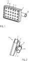
- figure 1 1 shows a perspective front view of an embodiment of a transportable/portable lamp 1 according to the invention.
- This has an approximately rectangular outline with a lamp housing 2 and a light exit opening 10 pointing forward.
- these components are LEDs. These are visible through a mask 17 with appropriate openings.
- the lamp housing 2 is attached to a place of use 4, here in particular to a partially shown tube 18.
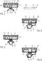
- FIG 2 is the light after figure 1 shown in a side perspective view.
- a voltage supply device 5 is fastened to the tube 18 by means of a tube clamp 19 and makes contact with the lamp housing 2 from behind.
- Corresponding fastening devices 11 with fastening means 12 for fastening the transportable lamp 1 to the tube 18 are also shown.
- the voltage supply device 5 is an inductive voltage supply device that forms a corresponding voltage supply for the lamp 1 wirelessly.
- FIGs 3 and 4 are sections through the lamp 1 after Figures 1 and 2 shown along the respective longitudinal axes.
- the fastening devices 11 have two fastening means 12 pointing away from one another at an angle. These are arranged in the middle on the back of the lamp housing 2 and can be designed so that their angle to one another can be changed or rotated relative to one another or relative to the lamp housing 2 .
- Each fastener 12 has a corresponding magnet 21 thereon.
- the respective fasteners 12 may be adaptable to different diameters of the pipe 18 by varying the angle between them.
- a switching device 14 in the form of a magnetic or tactile switch is shown in the middle between the two fastening means 12 . This detects a corresponding attachment of the lamp to the tube 18, see also figure 4 .
- a driver and control device 15 is arranged inside the housing. This controls, for example, the corresponding lighting means 3.
- the lighting means are LEDs, which are arranged on a printed circuit board 20 either in strips or in rows and columns in a planar manner.
- the corresponding mask 17 is assigned to the light exit opening 10 , the light exit opening still being bordered by a cover 23 of the lamp housing 2 .
- a backup power supply device 6 in the form of one or more batteries or accumulators 8 is arranged inside the lamp housing. These supply the lighting means 3 of the transportable lamp 1 when it is carried along by a user along a path. If the lamp is connected to the corresponding voltage supply device 5, the backup voltage supply device 6 is generally no longer used.
- the corresponding switching device 14 is part of a switching device 7 which causes such a switching between the voltage supply device and the backup voltage supply device. In this case, the switching device 7 is designed separately from the driver and control device 15 .
- FIG. 3 Next to the figure 3 another way of fastening the lamp at the place of use 4 is shown in dashed lines.
- corresponding fastening devices 11 on the lamp housing 2 are not required.
- a plate-shaped mounting device 13 is used, which is flat and can rest against the back of the lamp housing 2 .
- the mounting device 13 has one or more magnets 24 which serve to magnetically hold the lamp housing 2 and thus the transportable lamp 1 at the place of use 4 .
- figure 4 shows another longitudinal section through lamp 1.
- the voltage supply device 5 is located outside of the lamp housing 2 opposite a corresponding inductive voltage receiving device 22 .
- the voltage supply device 5 is detachably attached to the pipe 18 by means of a pipe clamp 19 .
- the driver and control device 15 can have a sensor 16 or is at least connected to it. The corresponding connection can also exist between sensor 16 and switching device 14 or switching device 7 .
- an electrical cable connection can also be made between, for example, an internal power supply unit of the lamp 1 and a corresponding external power supply device 5 .
- the corresponding sensor 16 can determine a corresponding mounting position of the transportable lamp 1 alone or with additional sensors 16 . This also applies in connection with the plate-shaped mounting device 13, in which, for example, the sensor 16 can be a magnetic sensor for detecting the corresponding holding magnets 24.
- figure 5 is a cut analogous to figure 3 represented by another embodiment of a lamp. This differs from the exemplary embodiment figure 3 in particular due to the lack of a switching device 7 with switching device 14. Instead, in this case the switching device 7 is part of the driver and control device 15. It is analogous to that Figures 3 or 4 detects a connection to the power supply device 5 or an attachment of the lamp at the place of use and switched by means of the switching device from power supply device 5 to backup power supply device 6 or vice versa. Furthermore, the corresponding sensor can be part of the inductive voltage receiving device 22 so that it detects a supply from the voltage supply device 5 and thus implements a corresponding switching by means of the switching device 7 .
- the power supply device 5 is fastened to the pipe 18 by means of a pipe clamp 19, for example.
- the portable lamp 1 can also be mechanical in addition or as an alternative be attached to the pipe 18, for example by means of a corresponding pipe clamp 19.
- a transportable light in which the light is operated from a backup power supply device 6 as long as it is not yet attached to the place of use and/or electrically connected to the power supply device 5 at the place of use 4 .
- the lamp can easily be carried along by a user along a path and used to adequately illuminate the path. If the transportable lamp 1 is at the place of use 4 and it is attached there using the appropriate fastening device and/or an electrical connection is made between the lamp and the voltage supply device 5, this is detected by the switching device 7 and converted into a switching command, which is carried out by means of driver and Control device 15 has a different illuminance and in particular a higher illuminance for the lamp at the location 4 .
- the switchover usually takes place automatically, i.e.
- Switching also takes place when a predetermined mounting position of the lamp at the place of use is detected by one or more sensors 16 .
- sensors 16 There is also the possibility that a corresponding switchover to the other and, in particular, higher illuminance level only takes place upon detection by two sensors.
- One of these sensors detects, for example, the attachment of the lamp at the place of use and the other sensor the correct or predetermined mounting position or the electrical connection to the power supply device.
- this electrical connection can be made either by a cable or wirelessly and, for example, inductively.
Landscapes
- Engineering & Computer Science (AREA)
- General Engineering & Computer Science (AREA)
- Arrangement Of Elements, Cooling, Sealing, Or The Like Of Lighting Devices (AREA)
- Circuit Arrangement For Electric Light Sources In General (AREA)
- Non-Portable Lighting Devices Or Systems Thereof (AREA)
Description
- Die Erfindung betrifft eine transportable Leuchte mit einem Leuchtengehäuse und zumindest einem in diesem angeordneten Leuchtmittel, welche Leuchte am Einsatzort befestigt und mit einer Spannungsversorgungseinrichtung verbindbar ist.
- Aus der Praxis sind eine Reihe von Leuchten bekannt, die man als transportable oder auch tragbare Leuchten bezeichnen kann. Zu den tragbaren Leuchten gehören beispielsweise Stableuchten, Taschenleuchten, Handleuchten, Handscheinwerfer oder auch Kopfleuchten. Diese weisen in der Regel eine interne Spannungsversorgungseinrichtung auf, wie eine Batterie, einen Akkumulator oder dergleichen. Diese tragbaren Leuchten sind einfach transportierbar und von einem Benutzer beispielsweise entlang eines Weges zum Ausleuchten mitführbar. Es gibt weitere transportable Leuchten, die beispielsweise an einem entsprechenden Einsatzort anflanschbar oder auch mittels einer Rohrschelle oder dergleichen an einem Mast, einem Rohr oder auch einer Wand oder einer Decke eines entsprechenden Raumes befestigbar sind. Solche transportablen Leuchten werden nach Befestigung am Einsatzort mit einer entsprechenden Spannungsversorgungseinrichtung verbunden. Allerdings können solche transportablen Leuchten nur am Einsatzort verwendet werden, da in der Regel kein einfaches Mitführen durch einen Benutzer möglich ist.
-
DE 102 09 031 A1 beschreibt eine Taschenlampe mit zwei Lichtquellen unterschiedlicher Intensität. Beide Lichtquellen werden unabhängig voneinander von unterschiedlichen Energiespeichern gespeist. Die erste Lichtquelle weist eine hohe Intensität und die zweite Lichtquelle eine geringere Lichtintensität auf. -
EP 2 762 764 A2 beschreibt eine Wandbeleuchtungseinheit mit einem Basismodul und einem Leuchtmodul. Das Basismodul weist eine Anschlusseinheit für eine Netzleitung, einen Converter, eine Regeleinrichtung eine Steckvorrichtung auf. Das Leuchtmodul weist mindestens eine LED-Leuchte, eine Steckvorrichtungsaufnahme, einen elektrischen Energiespeicher und eine Aktivierungseinrichtung auf. Sind Steckvorrichtung und Steckvorrichtungsaufnahme mechanisch und elektrisch miteinander verbunden, wird die LED-Leuchte von der Netzleitung über die Anschlusseinheit angesteuert. -
US 2014/139122 A1 beschreibt ein Beleuchtungssystem mit einer Mehrzahl von Leistungsversorgungen. Eine entsprechende Leuchte kann bspw. feststellen, ob eine erste und zweite Leistungsversorgung ausgeschaltet ist, um dann ggf. eine Batterieversorgung zu verwenden. Im Falle einer Batterieversorgung kann ggf. auch die Beleuchtungsintensität verändert werden. Neben den verschiedenen Leistungsversorgungen sind entsprechende Schalter vorhanden, die ebenso wie die entsprechenden Leuchten fest eingebaut sind. -
US 2012/262093 A1 beschreibt eine Beleuchtungseinrichtung mit wenigstens zwei Leistungsversorgungen, wobei eine Lichtintensität im Falle der Verwendung einer internen Batterie auf ein höheres oder geringeres Niveau umschaltbar ist. Die Beleuchtung erfolgt innerhalb eines Gebäudes. - Der Erfindung liegt die Aufgabe zugrunde, eine transportable/tragbare Leuchte nach dem Oberbegriff des Patentanspruchs 1 dahingehend zu verbessern, dass diese von einem Benutzer mitführbar ist, und ebenfalls am Einsatzort mit einer entsprechenden Spannungsversorgungseinrichtung verbindbar ist, wobei gleichzeitig der Energieverbrauch während des Mitführens durch einen Benutzer reduziert werden kann.
- Diese Aufgabe wird durch die Merkmale des Patentanspruchs 1 gelöst.
- Die Erfindung zeichnet sich insbesondere dadurch aus, dass die Leuchte eine insbesondere wiederaufladbare Ersatzspannungsversorgungseinrichtung und eine Umschalteinrichtung aufweist.
- Die Ersatzspannungsversorgungseinrichtung wird während des Mitführens der Leuchte eingesetzt, wobei eine entsprechende elektrische Verbindung zur Spannungsversorgungseinrichtung am Einsatzort erst dort durch beispielsweise den Benutzer der Leuchte erfolgt. Weiterhin dient die Umschalteinrichtung bei Befestigung der Leuchte am Einsatzort und/oder elektrische Verbindung der Leuchte mit der Spannungsversorgungseinrichtung zum
- Umschalten der Leuchte auf zumindest eine andere und insbesondere höhere Beleuchtungsstärke und/oder andere Lichtverteilung.
D.h., während des Mitführens der Leuchte hat diese eine relativ geringe Beleuchtungsstärke, die allerdings zur Beleuchtung des Weges oder dergleichen bei entsprechender Bewegung des Benutzers ausreicht. Erst am Einsatzort und nach Befestigung und/oder elektrischer Verbindung erfolgt dann ein Umschalten auf eine andere und insbesondere höhere Beleuchtungsstärke, wobei auch auf eine andere Lichtverteilung umschaltbar ist, um beispielsweise einen größeren Bereich auszuleuchten. - Bei einer günstigen Ausführungsform kann die Ersatzspannungsversorgungseinrichtung beispielsweise als Batterie oder Akkumulator ausgebildet sein. Solche sind in der Regel einfach aufladbar und können in entsprechender Anzahl oder Größe innerhalb der Leuchte angeordnet werden. Die Ersatzspannungsversorgung ist beispielsweise am Einsatzort über die Spannungsversorgungseinrichtung aufladbar.
- Am Einsatzort erfolgt dann unter den oben genannten Bedingungen ein entsprechendes Umschalten von der Ersatzspannungsversorgungseinrichtung auf die Spannungsversorgungseinrichtung. Diese ist in der Regel höher belastbar, sodass die Leuchte mit einer anderen und insbesondere höheren Beleuchtungsstärke betrieben werden kann.
- Für das oder die Leuchtmittel der Leuchte sind Leuchtmittel bevorzugt, die in ihrer Beleuchtungsstärke einstellbar sind. Einfache Ausführungsbeispiele für solche Leuchtmittel sind lichtemittierende Halbleiter-Bauelemente, wie LED, OLED oder dergleichen. Diese sind einzeln oder auch in Gruppen als Leuchtmittel anordbar. Ggf. können diese auch mit unterschiedlichen Farben verwendet werden.
- Um eine ausreichende Beleuchtungsstärke bei Einsatz der transportablen Leuchte zu ermöglichen, sind entsprechende lichtemittierende Halbleiter-Bauelemente leistenförmig, flächenförmig oder dergleichen angeordnet und insbesondere in Form von Chip-On-Board-Modulen ausgebildet. Diese sind in ihrer Leistung einfach einstellbar und können beispielsweise auch so betrieben werden, dass bei Verwendung der Ersatzspannungsversorgungseinrichtung nur einige der Leuchtmittel im Einsatz sind, während bei Verwendung mit der Spannungsversorgungseinrichtung alle Leuchtmittel eingesetzt werden.
- Weiterhin besteht die Möglichkeit, solche Leuchtmittel beispielsweise bei Verwendung mit der Ersatzspannungsversorgungeinrichtung zu dimmen, sodass sie eine geringere Beleuchtungsstärke als bei Verwendung mit der Spannungsversorgungseinrichtung aufweisen.
- Die Leuchte kann in unterschiedlicher Weise aufgebaut sein und bei einem einfachen Ausführungsbeispiel weist das Leuchtengehäuse wenigstens eine Lichtaustrittsöffnung und eine lösbare Befestigungseinrichtung auf. Die entsprechenden Leuchtmittel sind der oder den Lichtaustrittsöffnungen zugeordnet, wobei innerhalb der Leuchte, d.h. im Leuchtengehäuse, auch weitere Lichtleitmittel, wie Reflektoren, Filter oder dergleichen angeordnet sein können.
- Die lösbare Befestigungseinrichtung ist in der Regel am Leuchtengehäuse angeordnet oder zumindest mit diesem verbindbar. Solche lösbaren Befestigungseinrichtungen können in unterschiedlicher Weise ausgebildet sein. Einfache und leicht einzusetzende Befestigungseinrichtungen sind beispielsweise magnetische oder mechanische Befestigungseinrichtungen. D.h., das Leuchtengehäuse kann beispielsweise mittels Magneten direkt an einer entsprechenden Tafel, Masten oder dergleichen befestigt werden. Alternativ oder auch zusätzlich zu dieser magnetischen Befestigung kann eine mechanische Befestigung beispielsweise mittels Rohrschellen oder anderen lösbaren Befestigungsmitteln erfolgen.
- Um insbesondere die Leuchte an beispielsweise Rohren oder Masten unterschiedlicher Durchmesser befestigen zu können, kann die Befestigungseinrichtung zumindest zwei unter einem insbesondere veränderbaren Winkel zueinander geneigt anordbare und ggf. drehbare Befestigungsmittel aufweisen. Diese werden keilförmig von einer Seite auf Rohr oder Mast aufgesetzt und dann magnetisch und/oder mechanisch beispielsweise mittels einer Rohrschelle oder dergleichen befestigt.
- Nach dieser Befestigung kann entsprechend die Verbindung mit der Spannungsversorgungseinrichtung erfolgen.
- Es besteht ebenfalls die Möglichkeit, dass nicht direkt die Leuchte eine entsprechende Befestigungseinrichtung aufweist, sondern diese beispielsweise insbesondere in Form einer Montageeinrichtung am Einsatzort angeordnet ist. Eine solche Montageeinrichtung kann beispielsweise eine Montageplatte mit Haltemagneten, mit mechanischen Befestigungsmitteln oder anderen entsprechenden Einrichtungen sein.
- Eine einfache Möglichkeit zur elektrischen Verbindung von Leuchte und Spannungsversorgungseinrichtung kann darin gesehen werden, wenn ein entsprechendes Verbindungskabel mit Steckvorrichtungen verwendet wird. Ebenfalls ist denkbar, dass die elektrische Verbindung kabellos erfolgt. Eine solche kabellose Verbindung kann beispielsweise induktiv erfolgen. D.h., bei Befestigung der Leuchte an bestimmter Stelle erfolgt automatisch eine entsprechende induktive Kopplung zwischen Spannungsversorgungseinrichtung und entsprechender Einrichtung im Leuchtengehäuse. Durch diese automatische Verbindung kann dann ebenfalls die entsprechende Umschalteinrichtung ausgelöst werden, d.h. es erfolgt das Umschalten auf die andere, insbesondere höhere Beleuchtungsstärke.
- Wie bereits ausgeführt, wird in der Regel auf dem Weg zum Arbeitsplatz keine besonders hohe Beleuchtungsstärke erforderlich sein. Dies hat den weiteren Vorteil, dass beispielsweise die Ersatzspannungsversorgung innerhalb der Leuchte geringer belastet wird und eine längere Lebensdauer aufweist, d.h. auch weniger häufig aufgeladen werden muss.
- Es wurde bereits auf die entsprechenden lichtemittierenden Halbleiter-Bauelemente verwiesen, die bevorzugt als Leuchtmittel einsetzbar sind. Es besteht allerdings ebenfalls die Möglichkeit, andere Leuchtmittel zu verwenden. Bei diesen ist allerdings teilweise von Nachteil, dass diese weniger effizient in der Umsetzung von Energie in Licht oder aber nicht einfach dimmbar sind, siehe die verschiedenen Beleuchtungsstärken.
- Sobald eine elektrische Verbindung zur Spannungsversorgungseinrichtung hergestellt ist, kann es sich weiterhin als günstig erweisen, wenn zumindest ab der Herstellung dieser elektrischen Verbindung die elektrische Versorgung des Leuchtmittels von der Ersatzspannungsversorgungseinrichtung her unterbrochen ist. D.h., in einem solchen Fall wird die Leuchte allein von der Spannungsversorgungseinrichtung versorgt. Dies gilt nicht nur für die Leuchtmittel, sondern auch für alle weiteren Einrichtungen innerhalb der Leuchte, siehe beispielsweise Sensoren oder dergleichen, die in oder an der Leuchte angeordnet sein können.
- Um ein einfaches Umschalten beispielsweise von der Ersatzspannungsversorgungseinrichtung auf die Spannungsversorgungseinrichtung in diesem Zusammenhang zu ermöglichen, kann die Umschalteinrichtung eine Schalteinrichtung aufweisen, durch welche bei Befestigung der Leuchte am Einsatzort und/oder bei Verbindung der Leuchte mit der Spannungsversorgungseinrichtung ein Schaltsignal generierbar ist, durch welches zumindest auf die andere und insbesondere höhere Beleuchtungsstärke umschaltbar ist. Die entsprechende Umschalteinrichtung kann als separates Bauteil der Leuchte ausgebildet sein. Bevorzugt kann die Umschalteinrichtung allerdings Teil einer bereits vorhandenen Treiber- und Steuereinrichtung der Leuchte sein. Die Treibereinrichtung dient beispielsweise zum Betrieb der entsprechenden lichtemittierenden Halbleiter-Bauelemente oder anderer Leuchtmittel, siehe Leuchtstoffröhre mit Vorschaltgerät oder dergleichen.
- Die entsprechende Schalteinrichtung kann in unterschiedlicher Weise ausgebildet sein. Eins der oben genannten Ereignisse muss entsprechend detektierbar sein, um in ein Schaltsignal umgesetzt zu werden. Es sind beispielsweise Schalteinrichtungen denkbar, die zumindest einen magnetischen, induktiven, taktilen Sensor oder dergleichen aufweisen. Ein magnetischer Sensor kann beispielsweise verwendet werden, wenn Magneten zur Befestigung der Leuchte dienen, siehe die oben genannte Montageplatte mit Haltemagnete. Durch den magnetischen Sensor werden diese Haltemagnete detektiert und es erfolgt mittels der Umschalteinrichtung das bereits genannte Umschalten auf die andere Beleuchtungsstärke. Der Sensor kann ebenfalls die Verbindung mit der Spannungsversorgungseinrichtung detektieren, sodass bei Versorgung von der Spannungsversorgungseinrichtung her dann die Umschalteinrichtung tätig wird. Ein induktiver Sensor kann ebenfalls vorgesehen werden, um insbesondere eine induktive Spannungsversorgungseinrichtung zu detektieren, bei einer kabellosen elektrischen Verbindung. Außerdem kann mittels des induktiven Sensors oder auch der anderen Sensoren eine entsprechende Positionierung der Leuchte relativ zur Spannungsversorgungseinrichtung oder zur Befestigungseinrichtung erfasst werden. Das bedeutet, dass durch den Sensor beispielsweise die Spannungsversorgungseinrichtung, die Montageeinrichtung oder dergleichen erfassbar ist. Durch eine solche Erfassung kann auch eine vorgegebene Montageposition am Einsatzort durch den Sensor erfassbar sein. Wird beispielsweise eine entsprechende Montageplatte mit Haltemagneten verwendet, so kann durch entsprechende magnetische Sensoren der Leuchte die Position relativ zu den Haltemagneten erfasst werden und dadurch die entsprechende Montageposition.
- Es besteht weiterhin die Möglichkeit, dass diese vorbestimmte Montageposition durch einander kontaktierender und/oder ineinandergreifende Montagemittel der Montageeinrichtung und des Leuchtengehäuses bestimmt ist. Solche Mittel sind beispielsweise Vorsprünge an einer Montageplatte und entsprechende Vertiefungen in einer Gehäusewand des Leuchtengehäuses sein. Außerdem können auch direkt die Haltemagnete einer solchen Montageplatte in entsprechende Vertiefungen des Leuchtengehäuses eingreifen. Dadurch wird einerseits die Montage vereinfacht und andererseits gleichzeitig eine entsprechende Montageposition eingenommen.
- Es besteht weiterhin die Möglichkeit, nicht nur einen Sensor zu verwenden, sondern durch wenigstens zwei Sensoren der Schalteinrichtung die Montage oder auch vorbestimmte Montagepositionen und/oder Befestigung am Einsatzort und/oder elektrische Verbindung mit der Spannungsversorgungseinrichtung zu erfassen. D.h., nur wenn wenigstens zwei Sensoren ein entsprechendes Schaltsignal abgeben, erfolgt ein Umschalten mittels der Umschalteinrichtung. Ein Beispiel wäre ein Sensor, der beispielsweise die vorgegebene Montageposition erfasst und ein weiterer Sensor, der die elektrische Verbindung zur Spannungsversorgungseinrichtung detektiert. Geben beide entsprechende Schaltsignale ab, erfolgt dann ein Umschalten mittels der Umschalteinrichtung, d.h. ein Umschalten auf die andere insbesondere höhere Beleuchtungsstärke.
- Die entsprechende transportable/tragbare Leuchte kann ebenfalls an sich, als auch im Hinblick auf ihre Montage bzw. elektrische Verbindung mit der Spannungsversorgungseinrichtung entsprechend explosionsgeschützt ausgebildet sein, sodass sie in explosionsgefährdeten Bereichen zum Einsatz kommen kann. D.h., die erfindungsgemäße Leuchte kann ebenfalls eine transportable Ex-Leuchte sein. Weiterhin kann die Leuchte und insbesondere das Leuchtengehäuse aus einem entsprechenden Material, wie beispielsweise abriebfestem, schlagzähem Kunststoff hergestellt sein und nicht weiter dargestellte insbesondere ergonomisch gestaltete Leuchtenschalter können beispielsweise durch rastende Schieber oder dergleichen betätigt werden. Diese Schieber sind von außen am Leuchtengehäuse zugänglich. Es ist ebenfalls denkbar, dass ein entsprechendes Umschalten von Ersatzspannungsversorgungseinrichtungen auf Spannungsversorgungseinrichtungen durch ein manuelles Schalten an der Leuchte erfolgt.
- Im Folgenden werden vorteilhafte Ausführungsbeispiele der Erfindung anhand der in der Zeichnung beigefügten Figuren näher erläutert.
- Es zeigen:
- Figur 1:
- eine perspektivische Vorderansicht auf ein Ausführungsbeispiel einer erfindungsgemäßen transportablen/tragbaren Leuchte mit Rohrmontage;
- Figur 2:
- die transportable Leuchte nach
Figur 1 in einer perspektivischen Seitenansicht; - Figur 3:
- einen Schnitt durch eine Leuchte nach
Figuren 1 und 2 entlang einer Längsachse; - Figur 4:
- einen Schnitt durch eine Leuchte nach
Figuren 1 und 2 entlang einer weiteren Längsachse; - Figur 5:
- einen Längsschnitt analog zu
Figur 3 bei einem weiteren Ausführungsbeispiel, und - Figur 6:
- einen Schnitt analog zu
Figur 4 beim weiteren Ausführungsbeispiel. -
Figur 1 zeigt eine perspektivische Vorderansicht eines Ausführungsbeispiels einer transportablen/tragbaren Leuchte 1 gemäß Erfindung. Diese weist einen etwa rechteckförmigen Umriss auf mit einem Leuchtengehäuse 2 und einer nach vorne weisenden Lichtaustrittsöffnung 10. In dieser sind eine Reihe von in Spalten und Reihen angeordneten Leuchtmitteln 3 in Form von lichtemittierenden Halbleiter-Bauelementen 9 dargestellt. In diesem Fall sind diese Bauelemente LEDs. Diese sind durch eine Maske 17 mit entsprechenden Öffnungen sichtbar. Das Leuchtengehäuse 2 ist an einem Einsatzort 4 befestigt, hier insbesondere an einem teilweise dargestellten Rohr 18. - In
Figur 2 ist die Leuchte nachFigur 1 in einer seitlichen perspektivischen Ansicht dargestellt. Insbesondere ist erkennbar, dass eine Spannungsversorgungseinrichtung 5 mittels einer Rohrschelle 19 an dem Rohr 18 befestigt ist und von hinten das Leuchtengehäuse 2 kontaktiert. Entsprechende Befestigungseinrichtungen 11 mit Befestigungsmitteln 12 zur Befestigung der transportablen Leuchte 1 am Rohr 18 sind ebenfalls dargestellt. In diesem Fall ist die Spannungsversorgungseinrichtung 5 eine induktive Spannungsversorgungseinrichtung, die kabellos eine entsprechende Spannungsversorgung für die Leuchte 1 bildet. - In
Figuren 3 und 4 sind Schnitte durch die Leuchte 1 nachFiguren 1 und 2 entlang der entsprechenden Längsachsen dargestellt. NachFigur 3 weist die Befestigungseinrichtungen 11 zwei unter einem Winkel voneinander wegweisende Befestigungsmittel 12 auf. Diese sind mittig auf der Rückseite des Leuchtengehäuses 2 angeordnet und können sowohl in ihrem Winkel zueinander veränderbar als auch drehbar zueinander oder relativ zum Leuchtengehäuse 2 ausgebildet sein. Jedes Befestigungsmittel 12 weist einen entsprechenden Magneten 21 auf. Durch diesen, siehe auchFigur 2 , wird die transportable Leuchte 1 am Rohr 18 gehalten. Die entsprechenden Befestigungsmittel 12 können durch Variation des Winkels zwischen ihnen an unterschiedliche Durchmesser des Rohres 18 anpassbar sein. - Mittig zwischen den beiden Befestigungsmitteln 12 ist eine Schalteinrichtung 14 in Form eines magnetischen oder taktilen Schalters dargestellt. Dieser erfasst eine entsprechende Befestigung der Leuchte am Rohr 18, siehe auch
Figur 4 . Im Gehäuseinneren ist eine Treiber- und Steuereinrichtung 15 angeordnet. Diese steuert beispielsweise die entsprechenden Leuchtmittel 3. Bei dem dargestellten Ausführungsbeispiel sind die Leuchtmittel LEDs, die auf einer gedruckten Platine 20 entweder streifenförmig oder auch flächenförmig in Reihen und Spalten angeordnet sind. Der Lichtaustrittsöffnung 10 weist die entsprechende Maske 17 zu, wobei die Lichtaustrittsöffnung weiterhin von einer Abdeckung 23 des Leuchtengehäuses 2 umrandet ist. - Innerhalb des Leuchtengehäuses ist eine Ersatzspannungsversorgungseinrichtung 6 in Form von einer oder mehreren Batterien oder Akkumulatoren 8 angeordnet. Diese versorgen die Leuchtmittel 3 der transportablen Leuchte 1 bei Mitführen durch einen Benutzer entlang eines Weges. Erfolgt eine Verbindung der Leuchte mit der entsprechenden Spannungsversorgungseinrichtung 5 wird die Ersatzspannungsversorgungseinrichtung 6 in der Regel nicht mehr eingesetzt. Die entsprechende Schalteinrichtung 14 ist Teil einer Umschalteinrichtung 7, die ein solches Umschalten zwischen Spannungsversorgungseinrichtung und Ersatzspannungsversorgungseinrichtung bewirkt. In diesem Fall ist die Umschalteinrichtung 7 separat zur Treiber- und Steuereinrichtung 15 ausgebildet.
- Neben der
Figur 3 ist gestrichelt eine andere Art der Befestigung der Leuchte am Einsatzort 4 dargestellt. In diesem Fall sind entsprechende Befestigungseinrichtungen 11 am Leuchtengehäuse 2 nicht erforderlich. Stattdessen wird eine plattenförmige Montagevorrichtung 13 verwendet, die eben ist und an der Rückseite des Leuchtengehäuses 2 anliegen kann. Die Montageeinrichtung 13 weist einen oder mehrere Magnete 24 auf, die zum magnetischen Halten des Leuchtengehäuses 2 und damit der transportablen Leuchte 1 am Einsatzort 4 dienen. -
Figur 4 zeigt einen anderen Längsschnitt durch die Leuchte 1. - In diesem Fall ist weiterhin erkennbar, dass die Spannungsversorgungseinrichtung 5 außerhalb des Leuchtengehäuses 2 einer entsprechenden induktiven Spannungsempfangseinrichtung 22 gegenüberliegt. Die Spannungsversorgungseinrichtung 5 ist an dem Rohr 18 mittels einer Rohrschelle 19 lösbar befestigt. Weiterhin ist in
Figur 4 dargestellt, dass beispielsweise die Treiber- und Steuereinrichtung 15 einen Sensor 16 aufweisen kann oder zumindest mit diesem verbunden ist. Die entsprechende Verbindung kann auch zwischen Sensor 16 und Schalteinrichtung 14 bzw. Umschalteinrichtung 7 vorliegen. - Die Versorgung von der Spannungsversorgungseinrichtung 5 erfolgt bei dem Ausführungsbeispiel nach
Figur 3 und 4 drahtlos, wobei dies ebenfalls für das Ausführungsbeispiel auf denFiguren 5 und 6 gilt. Statt einer solchen drahtlosen Spannungsversorgung kann ebenfalls eine elektrische Kabelverbindung zwischen beispielsweise einer inneren Spannungsversorgungseinheit der Leuchte 1 und einer entsprechenden externen Spannungsversorgungseinrichtung 5 erfolgen. - Der entsprechende Sensor 16 kann allein oder auch mit weiteren Sensoren 16 eine entsprechende Montageposition der transportablen Leuchte 1 feststellen. Dies gilt ebenfalls im Zusammenhang mit der plattenförmigen Montageeinrichtung 13, bei der beispielsweise der Sensor 16 ein Magnetsensor zum Erfassen der entsprechenden Haltemagnete 24 sein kann.
- In
Figur 5 ist ein Schnitt analog zuFigur 3 durch ein weiteres Ausführungsbeispiel einer Leuchte dargestellt. Diese unterscheidet sich vom Ausführungsbeispiel nachFigur 3 insbesondere durch das Fehlen einer Umschalteinrichtung 7 mit Schalteinrichtung 14. Stattdessen ist in diesem Fall die Umschalteinrichtung 7 Teil der Treiber- und Steuereinrichtung 15. Es wird analog zu denFiguren 3 bzw. 4 eine Verbindung zur Spannungsversorgungseinrichtung 5 bzw. eine Befestigung der Leuchte am Einsatzort erfasst und mittels der Umschalteinrichtung von Spannungsversorgungseinrichtung 5 auf Ersatzspannungsversorgungseinrichtung 6 bzw. umgekehrt geschaltet. Weiterhin kann der entsprechende Sensor Teil der induktiven Spannungsempfangseinrichtung 22 sein, sodass dieser eine Versorgung von der Spannungsversorgungseinrichtung 5 her detektiert und damit ein entsprechendes Umschalten mittels der Umschalteinrichtung 7 realisiert. - Die entsprechende Befestigung des Leuchtengehäuses 2 nach den
Figuren 5 und 6 kann analog zu denFiguren 3 und 4 und ebenfalls mittels der zusätzlich inFigur 3 dargestellten Montageplatte 13 und entsprechender Haltemagnete 24 erfolgen. - Auch in
Figur 6 erfolgt die Befestigung der Spannungsversorgungseinrichtung 5 am Rohr 18 mittels beispielsweise einer Rohrschelle 19. - Statt der dargestellten Befestigungseinrichtung 11, siehe auch
Figur 2 , mit entsprechenden Befestigungsmitteln 12 kann auch die transportable Leuchte 1 zusätzlich oder alternativ mechanisch am Rohr 18 befestigt werden, beispielsweise mittels einer entsprechenden Rohrschelle 19. - Erfindungsgemäß wird eine transportable Leuchte bereitgestellt, bei der die Leuchte von einer Ersatzspannungsversorgungseinrichtung 6 her betrieben wird, solange sie noch nicht am Einsatzort befestigt und/oder elektrisch mit der Spannungsversorgungseinrichtung 5 am Einsatzort 4 verbunden ist. Dabei kann die Leuchte von einem Benutzer entlang eines Weges in einfacher Weise mitgeführt werden und zur ausreichenden Beleuchtung des Weges eingesetzt werden. Befindet sich die transportable Leuchte 1 am Einsatzort 4 und erfolgt dort eine Befestigung mittels der entsprechenden Befestigungseinrichtung und/oder eine elektrische Verbindung zwischen Leuchte und Spannungsversorgungseinrichtung 5, so wird dies von der Umschalteinrichtung 7 erfasst und in einen Schaltbefehl umgesetzt, durch den mittels Treiber- und Steuereinrichtung 15 eine andere Beleuchtungsstärke und insbesondere eine höhere Beleuchtungsstärke bei der Leuchte am Einsatzort 4 vorliegt. Das Umschalten erfolgt in der Regel automatisch, d.h. einfach bei entsprechender Detektion der Befestigung oder der Versorgung durch die Spannungsversorgungseinrichtung. Das Umschalten erfolgt ebenfalls, wenn eine vorbestimmte Montageposition der Leuchte am Einsatzort durch ein oder mehrere Sensoren 16 erfasst wird. Es besteht weiterhin die Möglichkeit, dass erst bei Detektion durch zwei Sensoren ein entsprechendes Umschalten auf die andere und insbesondere höhere Beleuchtungsstärke erfolgt. Einer dieser Sensoren erfasst beispielsweise die Befestigung der Leuchte am Einsatzort und der andere Sensor die korrekte bzw. vorbestimmte Montageposition oder die elektrische Verbindung mit der Spannungsversorgungseinrichtung. Wie bereits ausgeführt, kann diese elektrische Verbindung sowohl durch ein Kabel, als auch kabellos und beispielsweise induktiv erfolgen.
Claims (14)
- Transportable und tragbare Leuchte (1) mit einem Leuchtengehäuse (2) und zumindest einem in diesem angeordneten Leuchtmittel (3), welche Leuchte (1) am Einsatzort (4) befestigbar und mit einer Spannungsversorgungseinrichtung (5) verbindbar ist, wobei die Leuchte (1) eine wiederaufladbare Ersatzspannungsversorgungseinrichtung (6) und eine Umschalteinrichtung (7) aufweist, durch welche Umschalteinrichtung (7) bei Befestigung am Einsatzort (4) und elektrischer Verbindung mit der Spannungsversorgungseinrichtung (5) auf zumindest eine andere und höhere Beleuchtungsstärke und andere Lichtverteilung umschaltbar ist;
dadurch gekennzeichnet, dass:
die Umschalteinrichtung (7) eine Schalteinrichtung (14) aufweist, durch welche bei Befestigung am Einsatzort und elektrischer Verbindung mit der Spannungsversorgungseinrichtung (5) ein Schaltsignal generiert wird, durch welches zumindest auf die andere und höhere Beleuchtungsstärke und andere Lichtverteilung umschaltbar ist, und die Schalteinrichtung (14) zumindest einen magnetischen, induktiven oder taktilen Sensor (16) aufweist, wobei durch den Sensor (16) insbesondere die Spannungsversorgungseinrichtung (5) oder eine Montageeinrichtung (13) erfassbar ist. - Transportable und tragbare Leuchte nach Anspruch 1, dadurch gekennzeichnet, dass die Ersatzspannungsversorgungseinrichtung (6) als Batterie oder Akkumulator (8) ausgebildet ist.
- Transportable und tragbare Leuchte nach Anspruch 1 oder 2, dadurch gekennzeichnet, dass das Leuchtmittel (3) durch wenigstens eine oder insbesondere mehrere liehtemittierende Halbleiter-Bauelemente (9) gebildet ist, und dass diese leistenförmig, flächenförmig oder dergleichen angeordnet und insbesondere in Form von Chip-On-Board-Modulen ausgebildet sind.
- Transportable und tragbare Leuchte nach einem der vorangehenden Ansprüche, dadurch gekennzeichnet, dass Leuchtengehäuse (2) eine Lichtaustrittsöffnung (1 0) und eine diese umrandende Abdeckung (23) aufweist, die insbesondere in Lichtaustrittsrichtung transparent ausgebildet ist und eine lösbare Befestigungseinrichtung (11) aufweist, wobei die Befestigungseinrichtung (11) insbesondere eine magnetische oder mechanische Befestigungseinrichtung ist.
- Transportable und tragbare Leuchte nach Anspruch 4, dadurch gekennzeichnet, dass die Befestigungseinrichtung (11) zumindest zwei unter insbesondere einem veränderbaren Winkel zueinander geneigt anordbare und ggf. drehbare Befestigungsmittel (12) aufweist.
- Transportable und tragbare Leuchte nach Anspruch 4 oder 5, dadurch gekennzeichnet, dass die Befestigungseinrichtung (11) am Einsatzort (4) insbesondere in Form einer Montageeinrichtung (13) angeordnet ist, wobei die Montageeinrichtung (13) insbesondere als Montageplatte mit Haltemagneten ausgebildet ist.
- Transportable und tragbare Leuchte nach einem der vorangehenden Ansprüche, dadurch gekennzeichnet, dass zur elektrischen Verbindung von Leuchte (1) und Spannungsversorgungseinrichtung (5) ein Verbindungskabel vorgesehen ist.
- Transportable und tragbare Leuchte nach einem der vorangehenden Ansprüche, dadurch gekennzeichnet, dass die elektrische Verbindung von Leuchte (1) und Spannungsversorgungseinrichtung (5) kabellos erfolgt, wobei innerhalb des Leuchtengehäuses (1 0) insbesondere eine induktive Spannungsempfangseinrichtung (22) angeordnet ist.
- Transportable und tragbare Leuchte nach einem der vorangehenden Ansprüche, dadurch gekennzeichnet, dass zumindest insbesondere ab Herstellung der elektrischen Verbindung zwischen Leuchte (1) und Spannungsversorgungseinrichtung (5) eine elektrische Versorgung des Leuchtmittels (3) von der Ersatzspannungsversorgungseinrichtung (6) her unterbrochen ist.
- Transportable und tragbare Leuchte nach einem der vorangehenden Ansprüche, dadurch gekennzeichnet, dass die Umschalteinrichtung (7) Teil einer Treiber- und Steuereinrichtung (15) der Leuchte ist.
- Transportable und tragbare Leuchte nach Anspruch 1, dadurch gekennzeichnet, dass durch den Sensor (16) eine vorbestimmte Montageposition der Leuchte (1) am Einsatzort (4) erfassbar ist, wobei die vorbestimmte Montageposition insbesondere durch einander kontaktierende und/oder ineinander greifende Montagemittel von Montageeinrichtungen (13) und Leuchtengehäuse (2) bestimmt ist.
- Transportable und tragbare Leuchte nach einem der vorhergehendend Ansprüche, dadurch gekennzeichnet, dass durch wenigstens zwei Sensoren (16) der Schalteinrichtung (14) die vorbestimmte Montageposition und/oder die Befestigung am Einsatzort (4) und/oder die elektrische Verbindung der Leuchte mit der Spannungsversorgungseinrichtung (5) erfasst ist.
- Transportable und tragbare Leuchte nach einem der vorangehenden Ansprüche, dadurch gekennzeichnet, dass die Spannungsversorgungseinrichtung (5) entsprechend zum Leuchtengehäuse befestigbar ist und dieses insbesondere von einer Rückseite das Leuchtengehäuse (2) kontaktiert, wobei bei einer Befestigung an einem Rohr (18) insbesondere eine Rohrstelle (19) verwendbar ist.
- Verfahren zum Schalten einer transportablen und tragbaren Leuchte (1) nach Anspruch 1 mit folgenden Schritten:i) Betreiben der Leuchte (1) mit einer ersten Beleuchtungsstärke beim Mitführen bis zu einem Einsatzort (4);ii) Umschalten der Leuchte (1) auf eine zweite Beleuchtungsstärke höher als die erste Beleuchtungsstärke und auf eine andere Lichtverteilung am Einsatzort (4), wobei das Umschalten automatisch bei Befestigen der Leuchte (1) am Einsatzort (4) und bei elektrischer Verbindung der Leuchte (1) mit einer Spannungsversorgungseinrichtung (5) am Einsatzort (4) erfolgt.
Applications Claiming Priority (1)
| Application Number | Priority Date | Filing Date | Title |
|---|---|---|---|
| DE102016224067.6A DE102016224067A1 (de) | 2016-12-02 | 2016-12-02 | Transportable und tragbare leuchte und verfahren zum schalten einer solchen leuchte |
Publications (2)
| Publication Number | Publication Date |
|---|---|
| EP3330592A1 EP3330592A1 (de) | 2018-06-06 |
| EP3330592B1 true EP3330592B1 (de) | 2022-06-22 |
Family
ID=60480219
Family Applications (1)
| Application Number | Title | Priority Date | Filing Date |
|---|---|---|---|
| EP17203804.4A Active EP3330592B1 (de) | 2016-12-02 | 2017-11-27 | Transportable und tragbare leuchte und verfahren zum schalten einer solchen leuchte |
Country Status (2)
| Country | Link |
|---|---|
| EP (1) | EP3330592B1 (de) |
| DE (1) | DE102016224067A1 (de) |
Families Citing this family (1)
| Publication number | Priority date | Publication date | Assignee | Title |
|---|---|---|---|---|
| DE102021126078A1 (de) * | 2021-10-07 | 2023-04-13 | Metallwarenfabrik Gemmingen Gmbh | Anordnung aufweisend eine Einsatzleuchte und ein Handscheinwerfergehäuse |
Citations (6)
| Publication number | Priority date | Publication date | Assignee | Title |
|---|---|---|---|---|
| US20050265033A1 (en) * | 2004-05-25 | 2005-12-01 | Yang A M | Light device for attaching to various tools |
| US20110121654A1 (en) * | 2006-03-28 | 2011-05-26 | Recker Michael V | Remote switch sensing in lighting devices |
| US20120262093A1 (en) * | 2011-04-15 | 2012-10-18 | Recker Michael V | Lighting device capable of maintaining light intensity in demand response applications |
| US20140139019A1 (en) * | 2011-01-18 | 2014-05-22 | Enlighten Australia Pty Ltd | Lighting system |
| US20140139122A1 (en) * | 2012-11-19 | 2014-05-22 | Integrated Illumination Systems, Inc. | Systems and methods for multi-state power management |
| US20160223185A1 (en) * | 2015-02-04 | 2016-08-04 | Milwaukee Electric Tool Corporation | Light |
Family Cites Families (2)
| Publication number | Priority date | Publication date | Assignee | Title |
|---|---|---|---|---|
| DE10209031A1 (de) * | 2002-03-01 | 2003-09-18 | Swarovski Optik Kg | Taschenlampe mit zwei Lichtquellen unterschiedlicher Intensität |
| DE102013001741A1 (de) * | 2013-02-01 | 2014-08-07 | Abb Ag | Wandbeleuchtungseinheit |
-
2016
- 2016-12-02 DE DE102016224067.6A patent/DE102016224067A1/de not_active Withdrawn
-
2017
- 2017-11-27 EP EP17203804.4A patent/EP3330592B1/de active Active
Patent Citations (6)
| Publication number | Priority date | Publication date | Assignee | Title |
|---|---|---|---|---|
| US20050265033A1 (en) * | 2004-05-25 | 2005-12-01 | Yang A M | Light device for attaching to various tools |
| US20110121654A1 (en) * | 2006-03-28 | 2011-05-26 | Recker Michael V | Remote switch sensing in lighting devices |
| US20140139019A1 (en) * | 2011-01-18 | 2014-05-22 | Enlighten Australia Pty Ltd | Lighting system |
| US20120262093A1 (en) * | 2011-04-15 | 2012-10-18 | Recker Michael V | Lighting device capable of maintaining light intensity in demand response applications |
| US20140139122A1 (en) * | 2012-11-19 | 2014-05-22 | Integrated Illumination Systems, Inc. | Systems and methods for multi-state power management |
| US20160223185A1 (en) * | 2015-02-04 | 2016-08-04 | Milwaukee Electric Tool Corporation | Light |
Also Published As
| Publication number | Publication date |
|---|---|
| DE102016224067A1 (de) | 2018-06-07 |
| EP3330592A1 (de) | 2018-06-06 |
Similar Documents
| Publication | Publication Date | Title |
|---|---|---|
| EP1481847A2 (de) | Universalleuchte | |
| WO2013171148A1 (de) | Tragschiene zur halterung und stromversorgung mehrerer leuchtmodule, sowie lichtbandsystem mit einer solchen tragschiene | |
| EP3189269A1 (de) | Leuchte und verfahren zur anwesenheitsdetektion mittels einer solchen | |
| DE102007013129A1 (de) | Beleuchtungsvorrichtung, insbesondere netzunabhängige Beleuchtungsvorrichtung, und Beleuchtungsverbund | |
| EP2184817B1 (de) | Elektrisches Installationsgerät | |
| DE102012017016A1 (de) | Kühl- und/oder Gefriergerät | |
| DE60123428T2 (de) | Tragbare beleuchtungseinrichtung | |
| EP2330344B1 (de) | Veränderbare Leuchtvorrichtung | |
| EP3330592A1 (de) | Transportable und tragbare leuchte und verfahren zum schalten einer solchen leuchte | |
| AT8755U1 (de) | Kraftstoff-kanister | |
| DE102007043416B4 (de) | Notbeleuchtungsverfahren und -system | |
| DE202015003492U1 (de) | Arbeitslampe | |
| DE202011102371U1 (de) | Lichtquelle mit Energierückgewinnungs- und Speicherfunktion | |
| DE102006039745B4 (de) | Beleuchtungssystem | |
| DE9410782U1 (de) | Einrichtung zur Innenbeleuchtung von Behältnissen | |
| DE102008057007A1 (de) | Elektronisches Vorschaltgerät und Leuchtmittelsystem | |
| AT16273U1 (de) | Leuchte mit Solarzellen | |
| DE102011111970A1 (de) | LED-Modul-System mit einem LED-Modul | |
| DE20010821U1 (de) | Lampe | |
| EP1801488A1 (de) | Leuchte | |
| EP4163534A1 (de) | Anordnung aufweisend eine einsatzleuchte und ein handscheinwerfergehäuse | |
| DE202020100264U1 (de) | Nachtlicht | |
| DE102025126014A1 (de) | Tragbare Flächenleuchte | |
| DE102021001535A1 (de) | Pultleuchte | |
| DE202024106277U1 (de) | Solarenergie- und notstromspezifischer Energiespeicher |
Legal Events
| Date | Code | Title | Description |
|---|---|---|---|
| PUAI | Public reference made under article 153(3) epc to a published international application that has entered the european phase |
Free format text: ORIGINAL CODE: 0009012 |
|
| STAA | Information on the status of an ep patent application or granted ep patent |
Free format text: STATUS: THE APPLICATION HAS BEEN PUBLISHED |
|
| AK | Designated contracting states |
Kind code of ref document: A1 Designated state(s): AL AT BE BG CH CY CZ DE DK EE ES FI FR GB GR HR HU IE IS IT LI LT LU LV MC MK MT NL NO PL PT RO RS SE SI SK SM TR |
|
| AX | Request for extension of the european patent |
Extension state: BA ME |
|
| STAA | Information on the status of an ep patent application or granted ep patent |
Free format text: STATUS: REQUEST FOR EXAMINATION WAS MADE |
|
| 17P | Request for examination filed |
Effective date: 20181206 |
|
| RBV | Designated contracting states (corrected) |
Designated state(s): AL AT BE BG CH CY CZ DE DK EE ES FI FR GB GR HR HU IE IS IT LI LT LU LV MC MK MT NL NO PL PT RO RS SE SI SK SM TR |
|
| STAA | Information on the status of an ep patent application or granted ep patent |
Free format text: STATUS: EXAMINATION IS IN PROGRESS |
|
| 17Q | First examination report despatched |
Effective date: 20190820 |
|
| REG | Reference to a national code |
Ref country code: DE Ref legal event code: R079 Ref document number: 502017013353 Country of ref document: DE Free format text: PREVIOUS MAIN CLASS: F21L0004080000 Ipc: F21V0021088000 |
|
| RIC1 | Information provided on ipc code assigned before grant |
Ipc: H05B 47/105 20200101ALI20211117BHEP Ipc: F21V 21/088 20060101AFI20211117BHEP |
|
| GRAP | Despatch of communication of intention to grant a patent |
Free format text: ORIGINAL CODE: EPIDOSNIGR1 |
|
| STAA | Information on the status of an ep patent application or granted ep patent |
Free format text: STATUS: GRANT OF PATENT IS INTENDED |
|
| INTG | Intention to grant announced |
Effective date: 20220131 |
|
| GRAS | Grant fee paid |
Free format text: ORIGINAL CODE: EPIDOSNIGR3 |
|
| GRAA | (expected) grant |
Free format text: ORIGINAL CODE: 0009210 |
|
| STAA | Information on the status of an ep patent application or granted ep patent |
Free format text: STATUS: THE PATENT HAS BEEN GRANTED |
|
| AK | Designated contracting states |
Kind code of ref document: B1 Designated state(s): AL AT BE BG CH CY CZ DE DK EE ES FI FR GB GR HR HU IE IS IT LI LT LU LV MC MK MT NL NO PL PT RO RS SE SI SK SM TR |
|
| REG | Reference to a national code |
Ref country code: GB Ref legal event code: FG4D Free format text: NOT ENGLISH |
|
| REG | Reference to a national code |
Ref country code: CH Ref legal event code: EP |
|
| REG | Reference to a national code |
Ref country code: DE Ref legal event code: R096 Ref document number: 502017013353 Country of ref document: DE |
|
| REG | Reference to a national code |
Ref country code: AT Ref legal event code: REF Ref document number: 1499981 Country of ref document: AT Kind code of ref document: T Effective date: 20220715 |
|
| REG | Reference to a national code |
Ref country code: IE Ref legal event code: FG4D Free format text: LANGUAGE OF EP DOCUMENT: GERMAN |
|
| REG | Reference to a national code |
Ref country code: SE Ref legal event code: TRGR |
|
| REG | Reference to a national code |
Ref country code: LT Ref legal event code: MG9D |
|
| REG | Reference to a national code |
Ref country code: NL Ref legal event code: MP Effective date: 20220622 |
|
| PG25 | Lapsed in a contracting state [announced via postgrant information from national office to epo] |
Ref country code: NO Free format text: LAPSE BECAUSE OF FAILURE TO SUBMIT A TRANSLATION OF THE DESCRIPTION OR TO PAY THE FEE WITHIN THE PRESCRIBED TIME-LIMIT Effective date: 20220922 Ref country code: LT Free format text: LAPSE BECAUSE OF FAILURE TO SUBMIT A TRANSLATION OF THE DESCRIPTION OR TO PAY THE FEE WITHIN THE PRESCRIBED TIME-LIMIT Effective date: 20220622 Ref country code: HR Free format text: LAPSE BECAUSE OF FAILURE TO SUBMIT A TRANSLATION OF THE DESCRIPTION OR TO PAY THE FEE WITHIN THE PRESCRIBED TIME-LIMIT Effective date: 20220622 Ref country code: GR Free format text: LAPSE BECAUSE OF FAILURE TO SUBMIT A TRANSLATION OF THE DESCRIPTION OR TO PAY THE FEE WITHIN THE PRESCRIBED TIME-LIMIT Effective date: 20220923 Ref country code: FI Free format text: LAPSE BECAUSE OF FAILURE TO SUBMIT A TRANSLATION OF THE DESCRIPTION OR TO PAY THE FEE WITHIN THE PRESCRIBED TIME-LIMIT Effective date: 20220622 Ref country code: BG Free format text: LAPSE BECAUSE OF FAILURE TO SUBMIT A TRANSLATION OF THE DESCRIPTION OR TO PAY THE FEE WITHIN THE PRESCRIBED TIME-LIMIT Effective date: 20220922 |
|
| PG25 | Lapsed in a contracting state [announced via postgrant information from national office to epo] |
Ref country code: RS Free format text: LAPSE BECAUSE OF FAILURE TO SUBMIT A TRANSLATION OF THE DESCRIPTION OR TO PAY THE FEE WITHIN THE PRESCRIBED TIME-LIMIT Effective date: 20220622 Ref country code: LV Free format text: LAPSE BECAUSE OF FAILURE TO SUBMIT A TRANSLATION OF THE DESCRIPTION OR TO PAY THE FEE WITHIN THE PRESCRIBED TIME-LIMIT Effective date: 20220622 |
|
| PG25 | Lapsed in a contracting state [announced via postgrant information from national office to epo] |
Ref country code: NL Free format text: LAPSE BECAUSE OF FAILURE TO SUBMIT A TRANSLATION OF THE DESCRIPTION OR TO PAY THE FEE WITHIN THE PRESCRIBED TIME-LIMIT Effective date: 20220622 |
|
| PG25 | Lapsed in a contracting state [announced via postgrant information from national office to epo] |
Ref country code: SM Free format text: LAPSE BECAUSE OF FAILURE TO SUBMIT A TRANSLATION OF THE DESCRIPTION OR TO PAY THE FEE WITHIN THE PRESCRIBED TIME-LIMIT Effective date: 20220622 Ref country code: SK Free format text: LAPSE BECAUSE OF FAILURE TO SUBMIT A TRANSLATION OF THE DESCRIPTION OR TO PAY THE FEE WITHIN THE PRESCRIBED TIME-LIMIT Effective date: 20220622 Ref country code: RO Free format text: LAPSE BECAUSE OF FAILURE TO SUBMIT A TRANSLATION OF THE DESCRIPTION OR TO PAY THE FEE WITHIN THE PRESCRIBED TIME-LIMIT Effective date: 20220622 Ref country code: PT Free format text: LAPSE BECAUSE OF FAILURE TO SUBMIT A TRANSLATION OF THE DESCRIPTION OR TO PAY THE FEE WITHIN THE PRESCRIBED TIME-LIMIT Effective date: 20221024 Ref country code: ES Free format text: LAPSE BECAUSE OF FAILURE TO SUBMIT A TRANSLATION OF THE DESCRIPTION OR TO PAY THE FEE WITHIN THE PRESCRIBED TIME-LIMIT Effective date: 20220622 Ref country code: EE Free format text: LAPSE BECAUSE OF FAILURE TO SUBMIT A TRANSLATION OF THE DESCRIPTION OR TO PAY THE FEE WITHIN THE PRESCRIBED TIME-LIMIT Effective date: 20220622 Ref country code: CZ Free format text: LAPSE BECAUSE OF FAILURE TO SUBMIT A TRANSLATION OF THE DESCRIPTION OR TO PAY THE FEE WITHIN THE PRESCRIBED TIME-LIMIT Effective date: 20220622 |
|
| PG25 | Lapsed in a contracting state [announced via postgrant information from national office to epo] |
Ref country code: PL Free format text: LAPSE BECAUSE OF FAILURE TO SUBMIT A TRANSLATION OF THE DESCRIPTION OR TO PAY THE FEE WITHIN THE PRESCRIBED TIME-LIMIT Effective date: 20220622 Ref country code: IS Free format text: LAPSE BECAUSE OF FAILURE TO SUBMIT A TRANSLATION OF THE DESCRIPTION OR TO PAY THE FEE WITHIN THE PRESCRIBED TIME-LIMIT Effective date: 20221022 |
|
| REG | Reference to a national code |
Ref country code: DE Ref legal event code: R097 Ref document number: 502017013353 Country of ref document: DE |
|
| PG25 | Lapsed in a contracting state [announced via postgrant information from national office to epo] |
Ref country code: AL Free format text: LAPSE BECAUSE OF FAILURE TO SUBMIT A TRANSLATION OF THE DESCRIPTION OR TO PAY THE FEE WITHIN THE PRESCRIBED TIME-LIMIT Effective date: 20220622 |
|
| PG25 | Lapsed in a contracting state [announced via postgrant information from national office to epo] |
Ref country code: DK Free format text: LAPSE BECAUSE OF FAILURE TO SUBMIT A TRANSLATION OF THE DESCRIPTION OR TO PAY THE FEE WITHIN THE PRESCRIBED TIME-LIMIT Effective date: 20220622 |
|
| PLBE | No opposition filed within time limit |
Free format text: ORIGINAL CODE: 0009261 |
|
| STAA | Information on the status of an ep patent application or granted ep patent |
Free format text: STATUS: NO OPPOSITION FILED WITHIN TIME LIMIT |
|
| 26N | No opposition filed |
Effective date: 20230323 |
|
| P01 | Opt-out of the competence of the unified patent court (upc) registered |
Effective date: 20230521 |
|
| PG25 | Lapsed in a contracting state [announced via postgrant information from national office to epo] |
Ref country code: MC Free format text: LAPSE BECAUSE OF FAILURE TO SUBMIT A TRANSLATION OF THE DESCRIPTION OR TO PAY THE FEE WITHIN THE PRESCRIBED TIME-LIMIT Effective date: 20220622 |
|
| REG | Reference to a national code |
Ref country code: CH Ref legal event code: PL |
|
| PG25 | Lapsed in a contracting state [announced via postgrant information from national office to epo] |
Ref country code: LI Free format text: LAPSE BECAUSE OF NON-PAYMENT OF DUE FEES Effective date: 20221130 Ref country code: CH Free format text: LAPSE BECAUSE OF NON-PAYMENT OF DUE FEES Effective date: 20221130 |
|
| PG25 | Lapsed in a contracting state [announced via postgrant information from national office to epo] |
Ref country code: SI Free format text: LAPSE BECAUSE OF FAILURE TO SUBMIT A TRANSLATION OF THE DESCRIPTION OR TO PAY THE FEE WITHIN THE PRESCRIBED TIME-LIMIT Effective date: 20220622 Ref country code: LU Free format text: LAPSE BECAUSE OF NON-PAYMENT OF DUE FEES Effective date: 20221127 |
|
| PG25 | Lapsed in a contracting state [announced via postgrant information from national office to epo] |
Ref country code: IE Free format text: LAPSE BECAUSE OF NON-PAYMENT OF DUE FEES Effective date: 20221127 |
|
| PG25 | Lapsed in a contracting state [announced via postgrant information from national office to epo] |
Ref country code: FR Free format text: LAPSE BECAUSE OF NON-PAYMENT OF DUE FEES Effective date: 20221130 |
|
| REG | Reference to a national code |
Ref country code: AT Ref legal event code: MM01 Ref document number: 1499981 Country of ref document: AT Kind code of ref document: T Effective date: 20221127 |
|
| PG25 | Lapsed in a contracting state [announced via postgrant information from national office to epo] |
Ref country code: AT Free format text: LAPSE BECAUSE OF NON-PAYMENT OF DUE FEES Effective date: 20221127 |
|
| PGFP | Annual fee paid to national office [announced via postgrant information from national office to epo] |
Ref country code: BE Payment date: 20231019 Year of fee payment: 7 |
|
| PG25 | Lapsed in a contracting state [announced via postgrant information from national office to epo] |
Ref country code: HU Free format text: LAPSE BECAUSE OF FAILURE TO SUBMIT A TRANSLATION OF THE DESCRIPTION OR TO PAY THE FEE WITHIN THE PRESCRIBED TIME-LIMIT; INVALID AB INITIO Effective date: 20171127 |
|
| PG25 | Lapsed in a contracting state [announced via postgrant information from national office to epo] |
Ref country code: CY Free format text: LAPSE BECAUSE OF FAILURE TO SUBMIT A TRANSLATION OF THE DESCRIPTION OR TO PAY THE FEE WITHIN THE PRESCRIBED TIME-LIMIT Effective date: 20220622 |
|
| PG25 | Lapsed in a contracting state [announced via postgrant information from national office to epo] |
Ref country code: MK Free format text: LAPSE BECAUSE OF FAILURE TO SUBMIT A TRANSLATION OF THE DESCRIPTION OR TO PAY THE FEE WITHIN THE PRESCRIBED TIME-LIMIT Effective date: 20220622 |
|
| PG25 | Lapsed in a contracting state [announced via postgrant information from national office to epo] |
Ref country code: TR Free format text: LAPSE BECAUSE OF FAILURE TO SUBMIT A TRANSLATION OF THE DESCRIPTION OR TO PAY THE FEE WITHIN THE PRESCRIBED TIME-LIMIT Effective date: 20220622 |
|
| PG25 | Lapsed in a contracting state [announced via postgrant information from national office to epo] |
Ref country code: MT Free format text: LAPSE BECAUSE OF FAILURE TO SUBMIT A TRANSLATION OF THE DESCRIPTION OR TO PAY THE FEE WITHIN THE PRESCRIBED TIME-LIMIT Effective date: 20220622 |
|
| PG25 | Lapsed in a contracting state [announced via postgrant information from national office to epo] |
Ref country code: BG Free format text: LAPSE BECAUSE OF FAILURE TO SUBMIT A TRANSLATION OF THE DESCRIPTION OR TO PAY THE FEE WITHIN THE PRESCRIBED TIME-LIMIT Effective date: 20220622 |
|
| PG25 | Lapsed in a contracting state [announced via postgrant information from national office to epo] |
Ref country code: BG Free format text: LAPSE BECAUSE OF FAILURE TO SUBMIT A TRANSLATION OF THE DESCRIPTION OR TO PAY THE FEE WITHIN THE PRESCRIBED TIME-LIMIT Effective date: 20220622 |
|
| REG | Reference to a national code |
Ref country code: BE Ref legal event code: MM Effective date: 20241130 |
|
| PG25 | Lapsed in a contracting state [announced via postgrant information from national office to epo] |
Ref country code: BE Free format text: LAPSE BECAUSE OF NON-PAYMENT OF DUE FEES Effective date: 20241130 |
|
| PGFP | Annual fee paid to national office [announced via postgrant information from national office to epo] |
Ref country code: DE Payment date: 20251022 Year of fee payment: 9 |
|
| PGFP | Annual fee paid to national office [announced via postgrant information from national office to epo] |
Ref country code: GB Payment date: 20251023 Year of fee payment: 9 |
|
| PGFP | Annual fee paid to national office [announced via postgrant information from national office to epo] |
Ref country code: IT Payment date: 20251022 Year of fee payment: 9 |
|
| PGFP | Annual fee paid to national office [announced via postgrant information from national office to epo] |
Ref country code: SE Payment date: 20251022 Year of fee payment: 9 |