EP3330615A2 - Modelllose verbrennungsdynamik mit automatischer abstimmung - Google Patents
Modelllose verbrennungsdynamik mit automatischer abstimmung Download PDFInfo
- Publication number
- EP3330615A2 EP3330615A2 EP17204209.5A EP17204209A EP3330615A2 EP 3330615 A2 EP3330615 A2 EP 3330615A2 EP 17204209 A EP17204209 A EP 17204209A EP 3330615 A2 EP3330615 A2 EP 3330615A2
- Authority
- EP
- European Patent Office
- Prior art keywords
- combustor
- change
- fuel
- emissions
- amplitude
- Prior art date
- Legal status (The legal status is an assumption and is not a legal conclusion. Google has not performed a legal analysis and makes no representation as to the accuracy of the status listed.)
- Granted
Links
Images




Classifications
-
- F—MECHANICAL ENGINEERING; LIGHTING; HEATING; WEAPONS; BLASTING
- F23—COMBUSTION APPARATUS; COMBUSTION PROCESSES
- F23R—GENERATING COMBUSTION PRODUCTS OF HIGH PRESSURE OR HIGH VELOCITY, e.g. GAS-TURBINE COMBUSTION CHAMBERS
- F23R3/00—Continuous combustion chambers using liquid or gaseous fuel
- F23R3/28—Continuous combustion chambers using liquid or gaseous fuel characterised by the fuel supply
- F23R3/34—Feeding into different combustion zones
-
- F—MECHANICAL ENGINEERING; LIGHTING; HEATING; WEAPONS; BLASTING
- F02—COMBUSTION ENGINES; HOT-GAS OR COMBUSTION-PRODUCT ENGINE PLANTS
- F02C—GAS-TURBINE PLANTS; AIR INTAKES FOR JET-PROPULSION PLANTS; CONTROLLING FUEL SUPPLY IN AIR-BREATHING JET-PROPULSION PLANTS
- F02C7/00—Features, components parts, details or accessories, not provided for in, or of interest apart form groups F02C1/00 - F02C6/00; Air intakes for jet-propulsion plants
-
- F—MECHANICAL ENGINEERING; LIGHTING; HEATING; WEAPONS; BLASTING
- F02—COMBUSTION ENGINES; HOT-GAS OR COMBUSTION-PRODUCT ENGINE PLANTS
- F02C—GAS-TURBINE PLANTS; AIR INTAKES FOR JET-PROPULSION PLANTS; CONTROLLING FUEL SUPPLY IN AIR-BREATHING JET-PROPULSION PLANTS
- F02C9/00—Controlling gas-turbine plants; Controlling fuel supply in air- breathing jet-propulsion plants
-
- F—MECHANICAL ENGINEERING; LIGHTING; HEATING; WEAPONS; BLASTING
- F02—COMBUSTION ENGINES; HOT-GAS OR COMBUSTION-PRODUCT ENGINE PLANTS
- F02C—GAS-TURBINE PLANTS; AIR INTAKES FOR JET-PROPULSION PLANTS; CONTROLLING FUEL SUPPLY IN AIR-BREATHING JET-PROPULSION PLANTS
- F02C9/00—Controlling gas-turbine plants; Controlling fuel supply in air- breathing jet-propulsion plants
- F02C9/26—Control of fuel supply
-
- F—MECHANICAL ENGINEERING; LIGHTING; HEATING; WEAPONS; BLASTING
- F02—COMBUSTION ENGINES; HOT-GAS OR COMBUSTION-PRODUCT ENGINE PLANTS
- F02C—GAS-TURBINE PLANTS; AIR INTAKES FOR JET-PROPULSION PLANTS; CONTROLLING FUEL SUPPLY IN AIR-BREATHING JET-PROPULSION PLANTS
- F02C9/00—Controlling gas-turbine plants; Controlling fuel supply in air- breathing jet-propulsion plants
- F02C9/26—Control of fuel supply
- F02C9/28—Regulating systems responsive to plant or ambient parameters, e.g. temperature, pressure, rotor speed
-
- F—MECHANICAL ENGINEERING; LIGHTING; HEATING; WEAPONS; BLASTING
- F02—COMBUSTION ENGINES; HOT-GAS OR COMBUSTION-PRODUCT ENGINE PLANTS
- F02C—GAS-TURBINE PLANTS; AIR INTAKES FOR JET-PROPULSION PLANTS; CONTROLLING FUEL SUPPLY IN AIR-BREATHING JET-PROPULSION PLANTS
- F02C9/00—Controlling gas-turbine plants; Controlling fuel supply in air- breathing jet-propulsion plants
- F02C9/26—Control of fuel supply
- F02C9/32—Control of fuel supply characterised by throttling of fuel
- F02C9/34—Joint control of separate flows to main and auxiliary burners
-
- F—MECHANICAL ENGINEERING; LIGHTING; HEATING; WEAPONS; BLASTING
- F23—COMBUSTION APPARATUS; COMBUSTION PROCESSES
- F23R—GENERATING COMBUSTION PRODUCTS OF HIGH PRESSURE OR HIGH VELOCITY, e.g. GAS-TURBINE COMBUSTION CHAMBERS
- F23R2900/00—Special features of, or arrangements for continuous combustion chambers; Combustion processes therefor
- F23R2900/00013—Reducing thermo-acoustic vibrations by active means
Definitions
- This disclosure relates to turbomachines, and, more particularly, to systems and methods for tuning combustion dynamics in combustion systems.
- Combustion dynamics amplitude protection is needed in gas turbine operations.
- damage may result to the combustor and/or damage may result to parts of a machine (for example a gas turbine) on which the combustor is installed.
- High amplitude of the combustion dynamics may cause a relatively high vibration resulting in damage or a complete shutdown of the combustor and the machine.
- high amplitude of the combustion dynamics can result in an unsteady flame that, in turn, can lead to a flame blow out and cause a shutdown of the machine.
- This disclosure relates to systems and methods for tuning combustion dynamics in combustion systems. Certain embodiments of the disclosure can facilitate detecting a change in combustion dynamics amplitude of a combustor and determine a split change for the fuel circuits of the combustor to adjust the combustion dynamics amplitude level.
- a system for tuning of combustion dynamics may include a combustor and at least two fuel circuits configured to supply fuel to the combustor.
- the system may also include at least one sensor to detect and provide combustion dynamics amplitude data associated with the combustor.
- the system may further include an equipment controller communicatively coupled to the at least one sensor.
- the equipment controller may be configured to analyze the combustion dynamics amplitude data to detect at least one change in acoustic pressure amplitude associated with combustion in the combustor.
- the equipment controller may determine a fuel split change, wherein fuel split change is a change of the ratio of flow to the two fuel circuits.
- the equipment controller may further apply the fuel split change to the combustor.
- detection of the change in the acoustic pressure amplitude includes determining that the acoustic pressure amplitude exceeds a predefined dynamics amplitude threshold level for at least one vibrational frequency band of a set of ranges of frequencies.
- the fuel split change is determined based on a predefined split change direction and an amplitude variation from a default amplitude associated with the at least one vibrational frequency band.
- the split change direction is determined based on a minimum of predefined splits changes associated with the set of ranges of frequencies.
- the set of the ranges may include a range of frequencies from a relatively low range of frequencies to a relatively high range of frequencies.
- the predefined dynamics amplitude threshold level can be based on at least one of the following: a type of the combustor, acoustics inside the combustor, and a geometrical shape of the combustor.
- the system further comprises at least one sensor to detect and provide an emissions level associated with the combustor.
- the at least one sensor can be coupled to the equipment controller.
- the equipment controller can be further configured to determine that the emissions level exceeds a predefined emissions threshold. Based on determining that the emissions level exceeds the predefined emission threshold, the equipment controller can adjust control parameters of the combustor to correct the emissions level.
- the fuel split change is applied incrementally for a period of time until the at least one change in acoustic pressure amplitude in the combustor is eliminated.
- the period of time can be determined based on conditions of a site and needs and variability of a machine, the site and the machine being associated with the combustor.
- the equipment controller can be further configured to determine that amplitudes of the combustion dynamics are within predefined allowable limits and, based on the determination, increment the fuel split change to reduce a combustion dynamics level.
- the equipment controller can further provide the incremented fuel split change to an emissions algorithm configured to control emissions of the combustor and allow the emission algorithm to maintain the emissions within acceptable emissions limits.
- a method of tuning of combustion dynamics may include providing, via at least one sensor, combustion dynamics amplitude data associated with a combustor.
- the method may further allow monitoring, by an equipment controller communicatively coupled to the at least one sensor, the combustion dynamics amplitude data to detect at least one change in an acoustic pressure amplitude associated with combustion inside the combustor.
- the method can determine, by the equipment controller, a fuel split change, the fuel split change being a change of the ratio of flow to at least two fuel circuits configured to supply fuel to the combustor.
- the method can further include applying, by the equipment controller, the fuel split change to the combustor.
- Certain embodiments of the disclosure can include systems and methods for tuning combustion dynamics in combustion systems.
- the disclosed systems and methods can take into considerations ambient conditions, fuel variations, and/or age of the combustion system.
- the technology described herein can be utilized within new or existing control architectures to alleviate instabilities in combustion dynamics.
- the dynamics protection is integrated into the logic of an existing control of combustion systems, therefore, NOx emissions can also be kept within a compliant range.
- the dynamics protection technology described herein may use measured combustion dynamics to tune the combustion system in order to meet accepted levels of dynamics amplitudes in multiple frequency ranges.
- the described technology may eliminate the need for a highly specific and accurate model to provide a fast dynamics protection.
- a method for tuning combustion dynamics described herein can use a rate of change in a fuel circuit split to calculate desired split changes and provide these desired changes to an emissions control logic which can ensure that emission standards are being complied with.
- an equipment processor can monitor the combustion dynamics amplitude data to detect at least one change in acoustic pressure amplitude associated with combustion dynamics inside the combustor. In response to detecting at least one change in the acoustic pressure amplitude, the equipment controller can determine a fuel split change to at least two fuel circuits configured to supply fuel to the combustor. The equipment controller can apply the fuel split changes to the combustor.
- Certain embodiments of the disclosure can include eliminating the manual process of retuning the combustor. Certain embodiments of the disclosure can allow more aggressive fuel split scheduling with an active dynamics control inhibiting relatively high dynamics as desired, thereby minimizing or reducing the need to extrapolate for worst case dynamics scenarios. Further technical effects of certain embodiments of the disclosure can allow for automatic combustion dynamics protection. Further technical effects of certain embodiments of the disclosure can result in better part load operations for heat rate and emission compliant turndown. Yet further technical effects of certain embodiments of the disclosure can provide improvement in emission control and allow a reduction in combustion related trips, forced outage time, and unplanned costs.
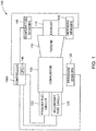
- FIG. 1 is a block diagram illustrating a combustion system 100, in accordance with an example embodiment of the disclosure.
- the system 100 may include a combustor 105, turbine 110, an exhaust 115, an equipment controller 1000, a primary fuel circuit 120, a secondary fuel circuit 125, pressure sensors 130, nitrogen oxides (NOx) sensors and temperature sensors 135.
- a primary fuel circuit 120 may be combined in a single instrument and/or integrated sensor device.
- Both the primary fuel circuit 120 and the secondary fuel circuit 125 can be configured to supply fuel the combustor 105 via fuel nozzles disposed inside the combustor 105.
- the fuel (a liquid fuel or a gaseous fuel) can be mixed with air and combusted in a chamber within the combustor 105, thereby creating hot pressurized exhaust gases.
- the combustor 105 directs the exhaust gases through a turbine 110 toward an exhaust system 115.
- a plurality of or multiple combustors 105 can be arranged circumferentially about the turbine 110.
- Each of the plurality of or multiple combustors 105 can be provided fuel via separate fuel circuits and include separate fuel nozzles.
- the exhaust gases force turbine blades to rotate a shaft along an axis of the turbine 110.
- the shaft may be connected to a load.
- the load may include a vehicle or a stationary load, such as an electrical generator in a power plant, a shaft driven compressor, and the like.
- the equipment controller 1000 can be communicatively connected to the primary fuel circuit 120, the secondary fuel circuit 125, acoustic pressure sensors 130, emissions sensors 135, and temperature sensors 145.
- the pressure sensors 130 can be configured to detect and provide combustion dynamics data related to the combustor 105.
- pressure sensors can include probes located inside the combustor 105.
- the probes can be configured to perform combustion dynamic monitoring. Specifically, the probes can be configured to convert the combustion dynamic pressure into an electrical signal.
- the electrical signal also referred to as a Continuous Dynamics Monitoring (CDM) signal, can be provided to equipment controller 1000 for analysis.
- the emissions sensors 135 can be configured to sense emissions level of nitrogen oxides and carbon oxides in exhaust gases.
- the temperature sensors 145 can be configured to sense emission temperature of the exhaust gases.
- the equipment controller 1000 can be configured to receive the combustion dynamics data, the emissions levels, and the exhaust temperature.
- the equipment controller 1000 can include a corrected parameter control (CPC) system 140.
- the CPC system 140 is configured to analyze the combustion dynamics data, the emissions level, the exhaust temperature, and adjust performance of combustor by controlling fuel flow in the primary fuel circuit 120 and the secondary fuel circuit 125.
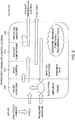
- FIG. 2 is a block diagram illustrating an example CPC system 140 broadly, according to an example embodiment of the disclosure.
- the example CPC system 140 can include target emissions module 205, a split control 210, an exhaust temperature module 215, and a prediction emissions module 220.
- target emissions module 205 is configured to estimate target emissions of a combustion system 100 based on a selection of a load, an ambient condition, a cycle of the turbine 110, and measured emissions of combustion system 100. In some embodiments of the disclosure, the target emission is estimated based on regulation limits and bias tuning of the combustion system 100.
- the target emissions can be provided to split control 210 and exhaust temperature module 215.
- the split control is configured to provide fuel splits between the primary fuel circuit and the secondary fuel circuit based on the target emissions.
- the fuel splits are adjusted based on a dynamics split.
- fuel splits are adjusted based on a NOx split and the dynamics split.
- the NOx split is a function of NOx emission.
- the dynamics split can be a function of combustion dynamics amplitudes of the combustor 105.
- exhaust temperature module 215 is configured to provide an exhaust temperature of combustions system 100.
- the predicted emission module 220 can be configured to predict emissions of the combustion system 100 based on an exhaust temperature, emission transfer functions and performance cycle analysis. The predicted emissions can be fed back to the target emissions module 205.
- FIG. 3 is a flow chart illustrating an example method 300 for automatic tuning of combustion dynamics, according to some embodiments of the disclosure.
- the operations of the method 300 can be performed by the combustion system 100 described above with reference to FIG. 1 .
- Method 300 can commence in block 302, with providing, by acoustic pressure sensors 130, the combustion dynamics amplitude data of the combustor 105.
- method 300 can proceed to monitoring, by the equipment controller 1000 (described in more detail below with reference to FIG.1 ), the combustion dynamics amplitude data to detect at least one change in acoustic pressure amplitude associated with combustion dynamics of the combustor 105.
- the equipment controller 1000 can be communicatively coupled to the acoustic pressure sensor 130 and provide the combustion dynamic amplitude data of the combustor 105.
- method 300 can proceed, in response to detecting at least one change in acoustic pressure amplitude, with determining, by the equipment controller 1000, a fuel split change.
- the fuel split change includes a change in the ratio of flow to the at least two fuel circuits (for example, the primary fuel circuit 120 and the secondary fuel circuit 125) configured to supply fuel to the combustor 105.
- the method 400 can include applying, by the equipment controller 1000, the fuel split change to the combustor.
- FIG. 4 is a flow chart illustrating an example method 400 for tuning of combustion dynamics, according to an embodiment of the disclosure.
- the operations of the method 1000 may be performed by the combustion system 100 described above with reference to FIG. 1 .
- method 400 can commence with performing CDM signal processing to obtain CDM input.
- method 400 can proceed with filtering the CDM input and selecting maximum amplitude for each frequency range in the CDM signal. In certain embodiments, the maximum amplitude can be determined for several ranges of frequencies
- the method 400 can proceed with determining, based on selected maximum amplitudes, splits for each frequency range.
- a broadband spectrum of CDM signal can be divided into several ranges of vibrational frequencies, as illustrated by Table 500 in FIG. 5 .
- Dynamics levels 505 can be pre-determined within each of the vibrational frequencies ranges.
- the maximum amplitude can be compared to the dynamics levels 505 to determine a direction (increase or decrease) and a value of split change 510 that should be used when the maximum amplitude reaches a certain dynamics level.
- dynamics levels 505 can include a low amplitude level (different for each frequency range) within which the split can be allowed to be increased. Increasing the split may result in improving emissions of the combustor.
- the dynamics levels may include an acceptable low amplitude level and an acceptable high amplitude level within which no change in split is required.
- the dynamics levels 505 can include a relatively high amplitude level. If the maximum amplitude reaches the high amplitude level, the change in the split includes a small decrease.
- the dynamics levels 505 can include a significantly high amplitude level. If the maximum amplitude reaches the significantly high amplitude level, it can result in a medium size decrease in the split change.
- the dynamics levels 505 can also include the highest amplitude level. If the maximum amplitude reaches the highest amplitude level, then a medium size decrease could be needed for the split change.
- the method 400 can select splits in each frequency range that result in a minimum split bias change.
- the method 400 may set, based on the selection, a split between fuel circuits of combustion system 100. It should be noted that when a split decrease can result in dropping a fuel flow in the primary fuel circuit 120 and increasing a fuel flow in the secondary fuel circuit 125. As a result, the flame inside the combustor can be stabilized. Stability of the flames can drive the dynamics amplitude to a lower value. However, when the flame stabilizes, emission values of the combustor can deteriorate.
- the combustion temperature is reduced to maintain emissions in conjunction with split change through tuning of combustion dynamics. In some embodiments of the disclosure, when dynamics amplitudes return to acceptable amplitude levels, the fuel split may be allowed to increase in order to improve emission values of the combustor 105.
- FIG. 6 is a flow chart illustrating an example method 600 for tuning of combustion dynamics, according to another embodiment of the disclosure.
- the operations of the method 600 may be performed by the combustion system 100.
- the method 600 may commence, in block 602, with determining that combustion dynamics are stable for a period of time. This period of time can depend on site conditions and specific needs of the machine on which the combustion system 100 is installed.
- the method 600 can proceed with enabling, based on the determination that combustion dynamics are relatively stable, a CDM tuning.
- the method 600 can add a split change bias to a minimum of a final dynamics split change and a NOx split change.
- the split change bias can be determined by the method 400 as described with reference to FIG. 4 above.
- the NOx split change is one of several control parameters of CPC system 140, which determines a base load selection, a turbine cycle, a measured emissions level, and a target emissions level.
- the method 600 may proceed with setting a split between fuel circuits and rate limits.
- operations of blocks 602-604 can be repeated recursively until dynamics amplitudes of the combustor 105 are within acceptable amplitude levels for all vibrational frequency ranges.
- FIG. 7 is a block diagram showing logic 700 for calculation of fuel split, according to some example embodiments of the disclosure.
- the logic 700 can be incorporated in CPC system 140.
- the logic 700 can include a split calculation module 705 and NOx temperature adjustment module 710.
- the split calculation module 705 is configured to determine a (fuel) split between fuel circuits.
- the fuel circuits can include the primary fuel circuit 120 and the secondary fuel circuit supplying fuel to the combustor 105.
- the split can be determined based only on the final dynamics split change.
- the final dynamic split can be adjusted based on a split bias determined based on changes in the combustion dynamics amplitude.
- the split can be determined based on both final dynamics split and NOx emissions split change.
- the NOx emission split change can be determined using an emission control loop by CPC system 140.
- final dynamics split change can be provided as a parameter to NOx temperature adjustment module 710.
- the module 710 can be configured to determine NOx temperature reference and a predicted NOx emission level.
- the CPC system 140 can use the NOx temperature reference and the predicted NOx emission level to adjust control parameters of combustion system 100.
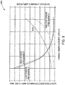
- FIG. 8 is an example plot 800 of combustion pressure amplitudes at several frequency ranges and NOx emissions as functions of the combustion temperature, in accordance with an embodiment of the disclosure.
- the combustion temperature can be controlled by setting a total fuel flow to the combustor.
- Dynamics amplitude at about 50 Hertz is a function of a relatively weak secondary flame, a low firing temperature, a low NOx emission, and a low secondary/high primary split.
- Dynamics amplitude at about 70 Hertz is a function of a relatively high primary split (with flame anchoring primarily on gas fuel), high firing temperature, and high NOx emissions.
- Dynamics amplitude at about 2400 Hertz is a function of relatively low secondary/high primary split, low firing temperature, and low firing frequency. Data concerning dependencies of dynamics amplitude from other combustion parameters can be used to determine selection of splits for each frequency region.
- FIG. 9 is an example plot 900 of NOx emissions and dynamics amplitude ratio to an optimal split as functions of a difference between a primary split and an optimal split, in accordance with an embodiment of the disclosure.
- the optimal split can be defined as a primary fuel split at which NOx emission reaches its minimum.
- dynamic amplitude can be lowered by decreasing a primary split, but decreasing of the primary fuel split can result in increasing of a NOx emission.
- FIG. 10 depicts a block diagram illustrating an example controller 1000, in accordance with an embodiment of the disclosure. More specifically, the elements of the controller 1000 may be used to run combustion system 100 under a plurality of operational conditions while within predetermined combustion operational boundaries, automatically collect operational data associated with the combustion system 100 while the combustion system 100 is running, store the operational data, generate a set of constants for one or more predetermined combustion transfer functions based on the operational data, and store the set of constants in the CPC system 140 to be used during the commissioning of the combustion fuel system.
- the controller 1000 may include a memory 1010 that stores programmed logic 1020 (e.g., software) and may store data 1030, such as operational data associated with the combustion fuel system, the set of constants, and the like.
- the memory 1010 also may include an operating system 1040.
- a processor 1050 may utilize the operating system 1040 to execute the programmed logic 1020, and in doing so, may also utilize the data 1030.
- a data bus 1060 may provide communication between the memory 1010 and the processor 1050.
- Users may interface with the controller 1000 via at least one user interface device 1070, such as a keyboard, mouse, control panel, or any other device capable of communicating data to and from the controller 1000.
- the controller 1000 may be in communication with the combustion system 100 while operating, as well as in communication with the CPC system 140 offline while not operating, via an input/output (I/O) interface 1080. Additionally, it should be appreciated that other external devices or multiple other combustion systems or combustors may be in communication with the controller 1000 via the I/O interface 1080.
- the controller 1000 may be located remotely with respect to the turbine system; however, it may be co-located or even integrated with the combustion system 100. Further, the controller 1000 and the programmed logic 1020 implemented thereby may include software, hardware, firmware, or any combination thereof. It should also be appreciated that multiple controllers 1000 maybe used, whereby different features described herein may be executed on one or more different controllers 400.
- references are made to block diagrams of systems, methods, apparatuses, and computer program products, according to example embodiments of the disclosure. It will be understood that at least some of the blocks of the block diagrams, and combinations of blocks in the block diagrams, may be implemented at least partially by computer program instructions. These computer program instructions may be loaded onto a general purpose computer, special purpose computer, special purpose hardware-based computer, or other programmable data processing apparatus to produce a machine, such that the instructions which execute on the computer or other programmable data processing apparatus create means for implementing the functionality of at least some of the blocks of the block diagrams, or combinations of blocks in the block diagrams discussed.
- These computer program instructions may also be stored in a computer-readable memory that can direct a computer or other programmable data processing apparatus to function in a particular manner, such that the instructions stored in the computer-readable memory produce an article of manufacture including instruction means that implement the function specified in the block or blocks.
- the computer program instructions may also be loaded onto a computer or other programmable data processing apparatus to cause a series of operational steps to be performed on the computer or other programmable apparatus to produce a computer implemented process such that the instructions that execute on the computer or other programmable apparatus provide steps for implementing the functions specified in the block or blocks.
- One or more components of the systems and one or more elements of the methods described herein may be implemented through an application program running on an operating system of a computer. They also may be practiced with other computer system configurations, including hand-held devices, multiprocessor systems, microprocessor based or programmable consumer electronics, mini-computers, mainframe computers, and the like.
- Application programs that are components of the systems and methods described herein may include routines, programs, components, data structures, and so forth that implement certain abstract data types and perform certain tasks or actions.
- the application program in whole or in part
- the application program may be located in local memory or in other storage.
- the application program in whole or in part
Landscapes
- Engineering & Computer Science (AREA)
- Chemical & Material Sciences (AREA)
- Combustion & Propulsion (AREA)
- Mechanical Engineering (AREA)
- General Engineering & Computer Science (AREA)
- Regulation And Control Of Combustion (AREA)
- Measuring Fluid Pressure (AREA)
Applications Claiming Priority (1)
| Application Number | Priority Date | Filing Date | Title |
|---|---|---|---|
| IN201641040986 | 2016-11-30 |
Publications (3)
| Publication Number | Publication Date |
|---|---|
| EP3330615A2 true EP3330615A2 (de) | 2018-06-06 |
| EP3330615A3 EP3330615A3 (de) | 2018-09-19 |
| EP3330615B1 EP3330615B1 (de) | 2020-10-28 |
Family
ID=60484229
Family Applications (1)
| Application Number | Title | Priority Date | Filing Date |
|---|---|---|---|
| EP17204209.5A Active EP3330615B1 (de) | 2016-11-30 | 2017-11-28 | Modelllose automatische regelung der verbrennungsdynamik |
Country Status (4)
| Country | Link |
|---|---|
| US (1) | US10830443B2 (de) |
| EP (1) | EP3330615B1 (de) |
| JP (1) | JP7106266B2 (de) |
| CN (1) | CN108119237B (de) |
Families Citing this family (2)
| Publication number | Priority date | Publication date | Assignee | Title |
|---|---|---|---|---|
| US11841139B2 (en) * | 2020-02-22 | 2023-12-12 | Honeywell International Inc. | Resonance prevention using combustor damping rates |
| IT202200001079A1 (it) * | 2022-01-24 | 2023-07-24 | Nuovo Pignone Tecnologie Srl | Sistema di turbina a gas con combustione a fiamma diffusiva e miscelazione di carburante per ridurre emissioni indesiderate |
Family Cites Families (27)
| Publication number | Priority date | Publication date | Assignee | Title |
|---|---|---|---|---|
| JP2667609B2 (ja) * | 1992-06-26 | 1997-10-27 | 株式会社東芝 | ガスタービン制御装置 |
| EP1724528A1 (de) * | 2005-05-13 | 2006-11-22 | Siemens Aktiengesellschaft | Verfahren und Vorrichtung zum Regeln der Fahrlinie einer Gasturbinenbrennkammer |
| GB2434437B (en) * | 2006-01-19 | 2011-01-26 | Siemens Ag | Improvements in or relating to combustion apparatus |
| CA2595061C (en) | 2007-07-23 | 2014-10-07 | General Electric Company | Method and apparatus for actively controlling fuel flow to a mixer assembly of a gas turbine engine combustor |
| JP4995657B2 (ja) * | 2007-07-23 | 2012-08-08 | ゼネラル・エレクトリック・カンパニイ | ガスタービンエンジン燃焼器のミキサ組立体への燃料流量を能動的に制御するための装置 |
| US8474268B2 (en) * | 2007-08-16 | 2013-07-02 | General Electric Company | Method of mitigating undesired gas turbine transient response using event based actions |
| US7631627B2 (en) * | 2007-10-30 | 2009-12-15 | Gm Global Technology Operations, Inc. | Voltage sag prevention apparatus and method |
| US9354618B2 (en) | 2009-05-08 | 2016-05-31 | Gas Turbine Efficiency Sweden Ab | Automated tuning of multiple fuel gas turbine combustion systems |
| US9267443B2 (en) | 2009-05-08 | 2016-02-23 | Gas Turbine Efficiency Sweden Ab | Automated tuning of gas turbine combustion systems |
| US8437941B2 (en) | 2009-05-08 | 2013-05-07 | Gas Turbine Efficiency Sweden Ab | Automated tuning of gas turbine combustion systems |
| US8417433B2 (en) | 2010-04-30 | 2013-04-09 | Alstom Technology Ltd. | Dynamically auto-tuning a gas turbine engine |
| US9927818B2 (en) | 2010-05-24 | 2018-03-27 | Ansaldo Energia Ip Uk Limited | Stabilizing a gas turbine engine via incremental tuning during transients |
| US8627668B2 (en) * | 2010-05-25 | 2014-01-14 | General Electric Company | System for fuel and diluent control |
| WO2013126279A1 (en) | 2012-02-22 | 2013-08-29 | Gas Turbine Efficiency Sweden Ab | Optimization of gas turbine combustion systems low load performance on simple cycle and heat recovery steam generator applications |
| EP2682587B1 (de) | 2012-07-05 | 2017-10-11 | Gas Turbine Efficiency Sweden AB | Automatisierte Regelung von Gasturbinenverbrennungssystemen |
| US20140182297A1 (en) | 2013-01-03 | 2014-07-03 | General Electric Company | Gas turbine and method of controlling a gas turbine at part-load condition |
| US9376963B2 (en) | 2013-01-16 | 2016-06-28 | Alstom Technology Ltd. | Detecting flashback by monitoring engine-dynamic spikes |
| US9014945B2 (en) | 2013-03-08 | 2015-04-21 | General Electric Company | Online enhancement for improved gas turbine performance |
| US9765701B2 (en) | 2013-03-15 | 2017-09-19 | General Electric Company | Gas turbine load enhancement |
| US9803560B2 (en) | 2013-03-15 | 2017-10-31 | Ansaldo Energia Ip Uk Limited | Dynamic tuning of a gas turbine engine to detect and prevent lean blowout |
| GB201317175D0 (en) | 2013-09-27 | 2013-11-06 | Rolls Royce Plc | An apparatus and a method of controlling the supply of fuel to a combustion chamber |
| DE102014002601B4 (de) | 2013-10-24 | 2019-08-29 | IfTA Ingenieurbüro für Thermoakustik GmbH | Anzeigeeinrichtung, Verfahren und Steuerung zur Analyse eines Schwingungsverhaltens eines Feuerungssystems |
| US20150142188A1 (en) | 2013-11-21 | 2015-05-21 | General Electric Company | Automated Commissioning of a Gas Turbine Combustion Control System |
| JP6217451B2 (ja) * | 2014-02-26 | 2017-10-25 | 三菱日立パワーシステムズ株式会社 | 燃料制御装置、燃焼器、ガスタービン、制御方法及びプログラム |
| US20150316266A1 (en) | 2014-04-30 | 2015-11-05 | Siemens Aktiengesellschaft | Burner with adjustable radial fuel profile |
| FR3025590B1 (fr) | 2014-09-10 | 2021-09-24 | Snecma | Repartition du debit en injection multipoints en fonction du rapport carburant/air dans la chambre de combustion |
| CN104533621B (zh) * | 2015-01-06 | 2016-08-24 | 中国科学院工程热物理研究所 | 一种双燃料注蒸汽正逆燃气轮机联合循环 |
-
2016
- 2016-12-27 US US15/391,450 patent/US10830443B2/en active Active
-
2017
- 2017-11-22 JP JP2017224122A patent/JP7106266B2/ja active Active
- 2017-11-28 EP EP17204209.5A patent/EP3330615B1/de active Active
- 2017-11-30 CN CN201711247750.9A patent/CN108119237B/zh active Active
Non-Patent Citations (1)
| Title |
|---|
| None |
Also Published As
| Publication number | Publication date |
|---|---|
| EP3330615B1 (de) | 2020-10-28 |
| CN108119237A (zh) | 2018-06-05 |
| JP7106266B2 (ja) | 2022-07-26 |
| US20180149363A1 (en) | 2018-05-31 |
| JP2018100661A (ja) | 2018-06-28 |
| CN108119237B (zh) | 2022-07-22 |
| EP3330615A3 (de) | 2018-09-19 |
| US10830443B2 (en) | 2020-11-10 |
Similar Documents
| Publication | Publication Date | Title |
|---|---|---|
| EP2031192B1 (de) | Verfahren und System zur Erkennung von Verbrennungsausblasungen einer Gasturbine mithilfe einer kraftstoffnormalisierten Leistungsreaktion | |
| JP4995169B2 (ja) | ガスタービン制御方法及び装置 | |
| US7743599B2 (en) | System and apparatus for gas turbine engine lean blowout avoidance | |
| JP4474132B2 (ja) | ガスタービンエンジンの燃焼器のための自動マッピング論理 | |
| KR101520240B1 (ko) | 밸브 제어 장치, 가스 터빈, 및 밸브 제어 방법 | |
| US9803560B2 (en) | Dynamic tuning of a gas turbine engine to detect and prevent lean blowout | |
| US9297315B2 (en) | Systems and methods for determining a target exhaust temperature for a gas turbine | |
| US8712665B2 (en) | Systems and methods for unchoked control of gas turbine fuel gas control valves | |
| JP5550592B2 (ja) | ガスタービンの制御装置 | |
| JP2009203943A (ja) | ガスタービン制御方法及び装置 | |
| CN102345515A (zh) | 用于控制燃料分流至燃气轮机燃烧器的方法 | |
| EP3191699B1 (de) | Massenflammentemperaturregler für dle-motoren | |
| US20150142188A1 (en) | Automated Commissioning of a Gas Turbine Combustion Control System | |
| JP2016037883A (ja) | 流量比算出装置、これを備えている制御装置、この制御装置を備えているガスタービンプラント、流量比算出方法、及び燃料系統の制御方法 | |
| EP3330615B1 (de) | Modelllose automatische regelung der verbrennungsdynamik | |
| US20140182297A1 (en) | Gas turbine and method of controlling a gas turbine at part-load condition | |
| US9964045B2 (en) | Methods and systems for detecting lean blowout in gas turbine systems | |
| CN107850306A (zh) | 具有时间序列与旁通滤波器的燃烧智能控制及相应系统 | |
| US11525409B2 (en) | Temperature based gas turbine control and method | |
| JP2017141728A (ja) | ガスタービン制御装置、ガスタービン制御方法及びプログラム | |
| JP5818945B2 (ja) | ガスタービンの制御方法及びガスタービンの燃空比設定方法 |
Legal Events
| Date | Code | Title | Description |
|---|---|---|---|
| PUAI | Public reference made under article 153(3) epc to a published international application that has entered the european phase |
Free format text: ORIGINAL CODE: 0009012 |
|
| STAA | Information on the status of an ep patent application or granted ep patent |
Free format text: STATUS: THE APPLICATION HAS BEEN PUBLISHED |
|
| AK | Designated contracting states |
Kind code of ref document: A2 Designated state(s): AL AT BE BG CH CY CZ DE DK EE ES FI FR GB GR HR HU IE IS IT LI LT LU LV MC MK MT NL NO PL PT RO RS SE SI SK SM TR |
|
| AX | Request for extension of the european patent |
Extension state: BA ME |
|
| PUAL | Search report despatched |
Free format text: ORIGINAL CODE: 0009013 |
|
| AK | Designated contracting states |
Kind code of ref document: A3 Designated state(s): AL AT BE BG CH CY CZ DE DK EE ES FI FR GB GR HR HU IE IS IT LI LT LU LV MC MK MT NL NO PL PT RO RS SE SI SK SM TR |
|
| AX | Request for extension of the european patent |
Extension state: BA ME |
|
| RIC1 | Information provided on ipc code assigned before grant |
Ipc: F23R 3/34 20060101AFI20180810BHEP |
|
| STAA | Information on the status of an ep patent application or granted ep patent |
Free format text: STATUS: REQUEST FOR EXAMINATION WAS MADE |
|
| 17P | Request for examination filed |
Effective date: 20190319 |
|
| RBV | Designated contracting states (corrected) |
Designated state(s): AL AT BE BG CH CY CZ DE DK EE ES FI FR GB GR HR HU IE IS IT LI LT LU LV MC MK MT NL NO PL PT RO RS SE SI SK SM TR |
|
| GRAP | Despatch of communication of intention to grant a patent |
Free format text: ORIGINAL CODE: EPIDOSNIGR1 |
|
| STAA | Information on the status of an ep patent application or granted ep patent |
Free format text: STATUS: GRANT OF PATENT IS INTENDED |
|
| INTG | Intention to grant announced |
Effective date: 20200527 |
|
| GRAS | Grant fee paid |
Free format text: ORIGINAL CODE: EPIDOSNIGR3 |
|
| GRAA | (expected) grant |
Free format text: ORIGINAL CODE: 0009210 |
|
| STAA | Information on the status of an ep patent application or granted ep patent |
Free format text: STATUS: THE PATENT HAS BEEN GRANTED |
|
| AK | Designated contracting states |
Kind code of ref document: B1 Designated state(s): AL AT BE BG CH CY CZ DE DK EE ES FI FR GB GR HR HU IE IS IT LI LT LU LV MC MK MT NL NO PL PT RO RS SE SI SK SM TR |
|
| REG | Reference to a national code |
Ref country code: GB Ref legal event code: FG4D |
|
| REG | Reference to a national code |
Ref country code: CH Ref legal event code: EP |
|
| REG | Reference to a national code |
Ref country code: AT Ref legal event code: REF Ref document number: 1328600 Country of ref document: AT Kind code of ref document: T Effective date: 20201115 |
|
| REG | Reference to a national code |
Ref country code: DE Ref legal event code: R096 Ref document number: 602017026250 Country of ref document: DE |
|
| REG | Reference to a national code |
Ref country code: IE Ref legal event code: FG4D |
|
| REG | Reference to a national code |
Ref country code: AT Ref legal event code: MK05 Ref document number: 1328600 Country of ref document: AT Kind code of ref document: T Effective date: 20201028 |
|
| REG | Reference to a national code |
Ref country code: NL Ref legal event code: MP Effective date: 20201028 |
|
| PG25 | Lapsed in a contracting state [announced via postgrant information from national office to epo] |
Ref country code: FI Free format text: LAPSE BECAUSE OF FAILURE TO SUBMIT A TRANSLATION OF THE DESCRIPTION OR TO PAY THE FEE WITHIN THE PRESCRIBED TIME-LIMIT Effective date: 20201028 Ref country code: GR Free format text: LAPSE BECAUSE OF FAILURE TO SUBMIT A TRANSLATION OF THE DESCRIPTION OR TO PAY THE FEE WITHIN THE PRESCRIBED TIME-LIMIT Effective date: 20210129 Ref country code: RS Free format text: LAPSE BECAUSE OF FAILURE TO SUBMIT A TRANSLATION OF THE DESCRIPTION OR TO PAY THE FEE WITHIN THE PRESCRIBED TIME-LIMIT Effective date: 20201028 Ref country code: PT Free format text: LAPSE BECAUSE OF FAILURE TO SUBMIT A TRANSLATION OF THE DESCRIPTION OR TO PAY THE FEE WITHIN THE PRESCRIBED TIME-LIMIT Effective date: 20210301 Ref country code: NO Free format text: LAPSE BECAUSE OF FAILURE TO SUBMIT A TRANSLATION OF THE DESCRIPTION OR TO PAY THE FEE WITHIN THE PRESCRIBED TIME-LIMIT Effective date: 20210128 |
|
| REG | Reference to a national code |
Ref country code: LT Ref legal event code: MG4D |
|
| PG25 | Lapsed in a contracting state [announced via postgrant information from national office to epo] |
Ref country code: ES Free format text: LAPSE BECAUSE OF FAILURE TO SUBMIT A TRANSLATION OF THE DESCRIPTION OR TO PAY THE FEE WITHIN THE PRESCRIBED TIME-LIMIT Effective date: 20201028 Ref country code: AT Free format text: LAPSE BECAUSE OF FAILURE TO SUBMIT A TRANSLATION OF THE DESCRIPTION OR TO PAY THE FEE WITHIN THE PRESCRIBED TIME-LIMIT Effective date: 20201028 Ref country code: LV Free format text: LAPSE BECAUSE OF FAILURE TO SUBMIT A TRANSLATION OF THE DESCRIPTION OR TO PAY THE FEE WITHIN THE PRESCRIBED TIME-LIMIT Effective date: 20201028 Ref country code: IS Free format text: LAPSE BECAUSE OF FAILURE TO SUBMIT A TRANSLATION OF THE DESCRIPTION OR TO PAY THE FEE WITHIN THE PRESCRIBED TIME-LIMIT Effective date: 20210228 Ref country code: PL Free format text: LAPSE BECAUSE OF FAILURE TO SUBMIT A TRANSLATION OF THE DESCRIPTION OR TO PAY THE FEE WITHIN THE PRESCRIBED TIME-LIMIT Effective date: 20201028 Ref country code: BG Free format text: LAPSE BECAUSE OF FAILURE TO SUBMIT A TRANSLATION OF THE DESCRIPTION OR TO PAY THE FEE WITHIN THE PRESCRIBED TIME-LIMIT Effective date: 20210128 Ref country code: SE Free format text: LAPSE BECAUSE OF FAILURE TO SUBMIT A TRANSLATION OF THE DESCRIPTION OR TO PAY THE FEE WITHIN THE PRESCRIBED TIME-LIMIT Effective date: 20201028 |
|
| PG25 | Lapsed in a contracting state [announced via postgrant information from national office to epo] |
Ref country code: HR Free format text: LAPSE BECAUSE OF FAILURE TO SUBMIT A TRANSLATION OF THE DESCRIPTION OR TO PAY THE FEE WITHIN THE PRESCRIBED TIME-LIMIT Effective date: 20201028 Ref country code: NL Free format text: LAPSE BECAUSE OF FAILURE TO SUBMIT A TRANSLATION OF THE DESCRIPTION OR TO PAY THE FEE WITHIN THE PRESCRIBED TIME-LIMIT Effective date: 20201028 |
|
| REG | Reference to a national code |
Ref country code: CH Ref legal event code: PL |
|
| REG | Reference to a national code |
Ref country code: DE Ref legal event code: R097 Ref document number: 602017026250 Country of ref document: DE |
|
| PG25 | Lapsed in a contracting state [announced via postgrant information from national office to epo] |
Ref country code: MC Free format text: LAPSE BECAUSE OF FAILURE TO SUBMIT A TRANSLATION OF THE DESCRIPTION OR TO PAY THE FEE WITHIN THE PRESCRIBED TIME-LIMIT Effective date: 20201028 Ref country code: LU Free format text: LAPSE BECAUSE OF NON-PAYMENT OF DUE FEES Effective date: 20201128 Ref country code: LT Free format text: LAPSE BECAUSE OF FAILURE TO SUBMIT A TRANSLATION OF THE DESCRIPTION OR TO PAY THE FEE WITHIN THE PRESCRIBED TIME-LIMIT Effective date: 20201028 Ref country code: EE Free format text: LAPSE BECAUSE OF FAILURE TO SUBMIT A TRANSLATION OF THE DESCRIPTION OR TO PAY THE FEE WITHIN THE PRESCRIBED TIME-LIMIT Effective date: 20201028 Ref country code: CZ Free format text: LAPSE BECAUSE OF FAILURE TO SUBMIT A TRANSLATION OF THE DESCRIPTION OR TO PAY THE FEE WITHIN THE PRESCRIBED TIME-LIMIT Effective date: 20201028 Ref country code: SM Free format text: LAPSE BECAUSE OF FAILURE TO SUBMIT A TRANSLATION OF THE DESCRIPTION OR TO PAY THE FEE WITHIN THE PRESCRIBED TIME-LIMIT Effective date: 20201028 Ref country code: RO Free format text: LAPSE BECAUSE OF FAILURE TO SUBMIT A TRANSLATION OF THE DESCRIPTION OR TO PAY THE FEE WITHIN THE PRESCRIBED TIME-LIMIT Effective date: 20201028 Ref country code: SK Free format text: LAPSE BECAUSE OF FAILURE TO SUBMIT A TRANSLATION OF THE DESCRIPTION OR TO PAY THE FEE WITHIN THE PRESCRIBED TIME-LIMIT Effective date: 20201028 |
|
| REG | Reference to a national code |
Ref country code: BE Ref legal event code: MM Effective date: 20201130 |
|
| PG25 | Lapsed in a contracting state [announced via postgrant information from national office to epo] |
Ref country code: CH Free format text: LAPSE BECAUSE OF NON-PAYMENT OF DUE FEES Effective date: 20201130 Ref country code: LI Free format text: LAPSE BECAUSE OF NON-PAYMENT OF DUE FEES Effective date: 20201130 Ref country code: DK Free format text: LAPSE BECAUSE OF FAILURE TO SUBMIT A TRANSLATION OF THE DESCRIPTION OR TO PAY THE FEE WITHIN THE PRESCRIBED TIME-LIMIT Effective date: 20201028 |
|
| PLBE | No opposition filed within time limit |
Free format text: ORIGINAL CODE: 0009261 |
|
| STAA | Information on the status of an ep patent application or granted ep patent |
Free format text: STATUS: NO OPPOSITION FILED WITHIN TIME LIMIT |
|
| 26N | No opposition filed |
Effective date: 20210729 |
|
| PG25 | Lapsed in a contracting state [announced via postgrant information from national office to epo] |
Ref country code: IT Free format text: LAPSE BECAUSE OF FAILURE TO SUBMIT A TRANSLATION OF THE DESCRIPTION OR TO PAY THE FEE WITHIN THE PRESCRIBED TIME-LIMIT Effective date: 20201028 Ref country code: AL Free format text: LAPSE BECAUSE OF FAILURE TO SUBMIT A TRANSLATION OF THE DESCRIPTION OR TO PAY THE FEE WITHIN THE PRESCRIBED TIME-LIMIT Effective date: 20201028 Ref country code: IE Free format text: LAPSE BECAUSE OF NON-PAYMENT OF DUE FEES Effective date: 20201128 Ref country code: FR Free format text: LAPSE BECAUSE OF NON-PAYMENT OF DUE FEES Effective date: 20201228 |
|
| PG25 | Lapsed in a contracting state [announced via postgrant information from national office to epo] |
Ref country code: SI Free format text: LAPSE BECAUSE OF FAILURE TO SUBMIT A TRANSLATION OF THE DESCRIPTION OR TO PAY THE FEE WITHIN THE PRESCRIBED TIME-LIMIT Effective date: 20201028 |
|
| PG25 | Lapsed in a contracting state [announced via postgrant information from national office to epo] |
Ref country code: IS Free format text: LAPSE BECAUSE OF FAILURE TO SUBMIT A TRANSLATION OF THE DESCRIPTION OR TO PAY THE FEE WITHIN THE PRESCRIBED TIME-LIMIT Effective date: 20210228 Ref country code: TR Free format text: LAPSE BECAUSE OF FAILURE TO SUBMIT A TRANSLATION OF THE DESCRIPTION OR TO PAY THE FEE WITHIN THE PRESCRIBED TIME-LIMIT Effective date: 20201028 Ref country code: MT Free format text: LAPSE BECAUSE OF FAILURE TO SUBMIT A TRANSLATION OF THE DESCRIPTION OR TO PAY THE FEE WITHIN THE PRESCRIBED TIME-LIMIT Effective date: 20201028 Ref country code: CY Free format text: LAPSE BECAUSE OF FAILURE TO SUBMIT A TRANSLATION OF THE DESCRIPTION OR TO PAY THE FEE WITHIN THE PRESCRIBED TIME-LIMIT Effective date: 20201028 |
|
| PG25 | Lapsed in a contracting state [announced via postgrant information from national office to epo] |
Ref country code: MK Free format text: LAPSE BECAUSE OF FAILURE TO SUBMIT A TRANSLATION OF THE DESCRIPTION OR TO PAY THE FEE WITHIN THE PRESCRIBED TIME-LIMIT Effective date: 20201028 |
|
| GBPC | Gb: european patent ceased through non-payment of renewal fee |
Effective date: 20211128 |
|
| PG25 | Lapsed in a contracting state [announced via postgrant information from national office to epo] |
Ref country code: BE Free format text: LAPSE BECAUSE OF NON-PAYMENT OF DUE FEES Effective date: 20201130 |
|
| PG25 | Lapsed in a contracting state [announced via postgrant information from national office to epo] |
Ref country code: GB Free format text: LAPSE BECAUSE OF NON-PAYMENT OF DUE FEES Effective date: 20211128 |
|
| REG | Reference to a national code |
Ref country code: DE Ref legal event code: R081 Ref document number: 602017026250 Country of ref document: DE Owner name: GENERAL ELECTRIC TECHNOLOGY GMBH, CH Free format text: FORMER OWNER: GENERAL ELECTRIC COMPANY, SCHENECTADY, NY, US |
|
| PGFP | Annual fee paid to national office [announced via postgrant information from national office to epo] |
Ref country code: DE Payment date: 20251022 Year of fee payment: 9 |