EP3330757B1 - Connecteur de fibre optique pouvant commuter la polarité de connexion - Google Patents
Connecteur de fibre optique pouvant commuter la polarité de connexion Download PDFInfo
- Publication number
- EP3330757B1 EP3330757B1 EP17169350.0A EP17169350A EP3330757B1 EP 3330757 B1 EP3330757 B1 EP 3330757B1 EP 17169350 A EP17169350 A EP 17169350A EP 3330757 B1 EP3330757 B1 EP 3330757B1
- Authority
- EP
- European Patent Office
- Prior art keywords
- outer housing
- wall
- optical fiber
- engagement
- fiber connector
- Prior art date
- Legal status (The legal status is an assumption and is not a legal conclusion. Google has not performed a legal analysis and makes no representation as to the accuracy of the status listed.)
- Active
Links
Images


Classifications
-
- G—PHYSICS
- G02—OPTICS
- G02B—OPTICAL ELEMENTS, SYSTEMS OR APPARATUS
- G02B6/00—Light guides; Structural details of arrangements comprising light guides and other optical elements, e.g. couplings
- G02B6/24—Coupling light guides
- G02B6/36—Mechanical coupling means
- G02B6/38—Mechanical coupling means having fibre to fibre mating means
- G02B6/3807—Dismountable connectors, i.e. comprising plugs
- G02B6/381—Dismountable connectors, i.e. comprising plugs of the ferrule type, e.g. fibre ends embedded in ferrules, connecting a pair of fibres
- G02B6/3826—Dismountable connectors, i.e. comprising plugs of the ferrule type, e.g. fibre ends embedded in ferrules, connecting a pair of fibres characterised by form or shape
- G02B6/3831—Dismountable connectors, i.e. comprising plugs of the ferrule type, e.g. fibre ends embedded in ferrules, connecting a pair of fibres characterised by form or shape comprising a keying element on the plug or adapter, e.g. to forbid wrong connection
-
- G—PHYSICS
- G02—OPTICS
- G02B—OPTICAL ELEMENTS, SYSTEMS OR APPARATUS
- G02B6/00—Light guides; Structural details of arrangements comprising light guides and other optical elements, e.g. couplings
- G02B6/24—Coupling light guides
- G02B6/36—Mechanical coupling means
- G02B6/38—Mechanical coupling means having fibre to fibre mating means
- G02B6/3807—Dismountable connectors, i.e. comprising plugs
- G02B6/381—Dismountable connectors, i.e. comprising plugs of the ferrule type, e.g. fibre ends embedded in ferrules, connecting a pair of fibres
- G02B6/3818—Dismountable connectors, i.e. comprising plugs of the ferrule type, e.g. fibre ends embedded in ferrules, connecting a pair of fibres of a low-reflection-loss type
- G02B6/3821—Dismountable connectors, i.e. comprising plugs of the ferrule type, e.g. fibre ends embedded in ferrules, connecting a pair of fibres of a low-reflection-loss type with axial spring biasing or loading means
-
- G—PHYSICS
- G02—OPTICS
- G02B—OPTICAL ELEMENTS, SYSTEMS OR APPARATUS
- G02B6/00—Light guides; Structural details of arrangements comprising light guides and other optical elements, e.g. couplings
- G02B6/24—Coupling light guides
- G02B6/36—Mechanical coupling means
- G02B6/38—Mechanical coupling means having fibre to fibre mating means
- G02B6/3807—Dismountable connectors, i.e. comprising plugs
- G02B6/3873—Connectors using guide surfaces for aligning ferrule ends, e.g. tubes, sleeves, V-grooves, rods, pins, balls
- G02B6/3882—Connectors using guide surfaces for aligning ferrule ends, e.g. tubes, sleeves, V-grooves, rods, pins, balls using rods, pins or balls to align a pair of ferrule ends
-
- G—PHYSICS
- G02—OPTICS
- G02B—OPTICAL ELEMENTS, SYSTEMS OR APPARATUS
- G02B6/00—Light guides; Structural details of arrangements comprising light guides and other optical elements, e.g. couplings
- G02B6/24—Coupling light guides
- G02B6/36—Mechanical coupling means
- G02B6/38—Mechanical coupling means having fibre to fibre mating means
- G02B6/3807—Dismountable connectors, i.e. comprising plugs
- G02B6/389—Dismountable connectors, i.e. comprising plugs characterised by the method of fastening connecting plugs and sockets, e.g. screw- or nut-lock, snap-in, bayonet type
- G02B6/3893—Push-pull type, e.g. snap-in, push-on
-
- G—PHYSICS
- G02—OPTICS
- G02B—OPTICAL ELEMENTS, SYSTEMS OR APPARATUS
- G02B6/00—Light guides; Structural details of arrangements comprising light guides and other optical elements, e.g. couplings
- G02B6/24—Coupling light guides
- G02B6/36—Mechanical coupling means
- G02B6/38—Mechanical coupling means having fibre to fibre mating means
- G02B6/3807—Dismountable connectors, i.e. comprising plugs
- G02B6/381—Dismountable connectors, i.e. comprising plugs of the ferrule type, e.g. fibre ends embedded in ferrules, connecting a pair of fibres
- G02B6/3825—Dismountable connectors, i.e. comprising plugs of the ferrule type, e.g. fibre ends embedded in ferrules, connecting a pair of fibres with an intermediate part, e.g. adapter, receptacle, linking two plugs
-
- G—PHYSICS
- G02—OPTICS
- G02B—OPTICAL ELEMENTS, SYSTEMS OR APPARATUS
- G02B6/00—Light guides; Structural details of arrangements comprising light guides and other optical elements, e.g. couplings
- G02B6/24—Coupling light guides
- G02B6/36—Mechanical coupling means
- G02B6/38—Mechanical coupling means having fibre to fibre mating means
- G02B6/3807—Dismountable connectors, i.e. comprising plugs
- G02B6/3873—Connectors using guide surfaces for aligning ferrule ends, e.g. tubes, sleeves, V-grooves, rods, pins, balls
- G02B6/3885—Multicore or multichannel optical connectors, i.e. one single ferrule containing more than one fibre, e.g. ribbon type
Definitions
- the disclosure relates to an optical fiber connector, and more particularly, to an optical fiber connector capable of changing connection polarity.
- Optical fiber connectors are an essential part of substantially all optical fiber communication systems. For instance, such connectors are used to join segments of fiber into longer lengths, to connect fiber to active devices such as radiation sources, detectors and repeaters, and to connect fiber to passive devices such as switches and attenuators.
- the principal function of optical fiber connectors is to hold an optical fiber such that its core is axially aligned with the optical path of the device to which the connector is mating. This way the light from one fiber is optically coupled to the optical path of the mating device.
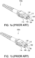
- FIGS. 1a and 1b respectively illustrate conventional multi-fiber MPO male and female type connectors 110a, 110b.
- Each of the optical fiber connectors 100a and 100b has a rectangular key protrusion 112 formed on the upper surface of the front section thereof. Located on two opposing lateral surfaces of the front section are two indentations 114. A plurality of optical fibers 130 are exposed from and flush with the front end surface 120 of the front section. Two guide pins 140 protrude from the end surface 120 of the optical fiber connector 100a while two guide holes 150 are formed on the end surface 120 of the optical fiber connector 100b to respectively receive the guide pins 140 of the connector 100a.
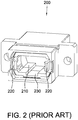
- FIG. 2 illustrates a conventional MPO type optical fiber adapter 200.
- the optical fiber adapter 200 has a hollow main body with two opposing openings 210 in an axial direction into which the connectors 100a and 100b may be respectively inserted.
- two pairs of hooks 220 are positioned to respectively extend out from the openings 210 of the adapter 200.
- two rectangular key recesses 230 are formed on the inner walls of the adapter 200 respectively near the openings 210 to receive the key protrusions 112 of the connectors 100a and 100b.
- the hooks 220 will respectively hook on to the connectors 100a, 100b at the indentations 114.
- the guide pins 140 of the connector 100a are respectively inserted into the guide holes 150 of the connector 100b and the optical fibers 130 exposed out from the connectors 100a and 100b are brought into contact with each other accordingly. This way the light from one fiber may be optically coupled to the coupled fiber.
- the function of the key recesses 230 is to receive the key protrusions 112 at the connectors 100a, 100b such that the connectors 100a, 100b may be inserted into the adapter 200 with only predetermined orientations.
- FIG. 2 when the connector 100a or 100b of FIGS. 1a, 1b is positioned with its key protrusion 112 being oriented up, it cannot be inserted into the adapter 200 through the openings 210.
- the connector 100a or 100b is turned over such that the key protrusion 112 is oriented down, it may be inserted into the adapter 200. Therefore, the orientations of the key recesses 230 restrict the coupling of the connectors 100a and 100b to the predetermined polarity.
- a conventional connector providing a polarity changing function is known from WO 2015/103783 A1 , wherein said connector includes two connector portions and a boot and each connector portion includes a latch having a distal end and a proximal end, wherein said latch is pivotable about an intermediate connection portion, wherein front housings of the connector portions can be rotated to change the polarity of the two connector portions.
- Document US 2015/277059 A1 discloses another conventional connector providing a polarity changing function, said connector including a housing assembly, a first fiber optic connector, a second fiber optic connector and an attachment mechanism for releasably attaching each of the first and second fiber optic connectors to the housing assembly.
- the present disclosure therefore provides an optical fiber connector capable of changing connection polarity according to claim 1.
- the optical fiber connector 300 may be an MPO type optical fiber connector and includes a spring push 10, a spring 20, a spring seat 30, a ferrule 40, an inner housing 50, a first outer housing 60 and a second outer housing 70.
- the spring push 10 may be constructed of plastics by an injection molding process and include a forward portion 11 and a flange 12.
- the flange 12 is hollow and substantially has a rectangular shape in cross section.
- the forward portion 11 extends forward from the flange 12 in a lengthwise or axial direction.
- Two flexible arms 14 provided on the spring push 10 depend lengthwise from the forward portion 11.
- An opening 15 extends lengthwise through the spring push 10 from the flange 12 to the forward portion 11.
- Engagement protrusions 17 are respectively formed on outer surfaces of the flexible arms 14.
- the spring 20 may be a coil spring and extend lengthwise.
- the spring 20 has a front end 21 and a rear end 22.
- An opening 23 extends lengthwise through the spring 20 from the rear end 22 to the front end 21 and comes in communication with the opening 15 of the spring push 10 when the spring 20 is, at its rear end 22, brought into contact with the forward portion 11 of the spring push 10.
- the spring seat 30 may be constructed of plastics by an injection molding process and include a body substantially having a U-shaped cross section.
- the spring seat 30 has a front surface 31 and an opposed rear surface 32.
- a pair of guide pins 33 extends lengthwise or axially from the front surface 31 and a pair of restricting walls 34 extends backward from the rear surface 32.
- the two restricting walls 34 are positioned to face each other and the inner side surfaces thereof are curved and concave.
- a rectangular opening 35 extends lengthwise through the spring seat 30 from the rear surface 32 to the front surface 31.
- the ferrule 40 may be an MT-type multi-fiber ferrule and substantially have a rectangular shape in cross section.
- the ferrule 40 has a body extending lengthwise and opposing front and rear surfaces 41, 42.
- Two circular holes 44 open through the rear surface 42 and are configured to respectively receive the guide pins 33 of the spring seat 30.
- a rectangular opening 46 is formed through the rear surface 42 and located between the holes 44.
- the opening 46 extends lengthwise from the rear surface 42 toward the front surface 41.
- the ferrule 40 defines a plurality of bores 43 that open through the front surface 41 and are in communication with the opening 46.
- the bores 43 are arranged in a laterally extending linear row for receiving the end portions of respective optical fibers of a ribbon fiber that can be inserted into the opening 46 from the rear surface 42.
- the inner housing 50 may be constructed of plastics by an injection molding process.
- the inner housing 50 is hollow and substantially has a rectangular shape in cross section.
- the inner housing 50 extends lengthwise or axially and has an accommodation room 515 defined by a top wall 511, a bottom wall 512, a right wall 513 and a left wall 514, wherein the top wall 511 faces the bottom wall 512 and connects with the right wall 513 and left wall 514.
- the accommodation room 515 has a front opening 517 and an opposed rear opening 518 in the lengthwise or axial direction.
- Engagement openings 516 are respectively formed through the right wall 513 and the left wall 514 for engaging the engagement protrusions 17 of the spring push 10.
- Two elongated grooves 521 and 522 are formed near the front opening 517 on outer surfaces of the top wall 511 and bottom wall 512 respectively.
- the grooves 521, 522 may be dovetail grooves and are positioned corresponding to each other.
- the grooves 521, 522 extend lengthwise or axially to the front edges of the top and bottom walls 511, 512 respectively.
- stop blocks 531 and 532 are respectively formed on the outer surfaces of the top wall 511 and bottom wall 512.
- the stop blocks 531 and 532 define respective angled or ramped outer surfaces, which are ramped up toward the rear edges of the top and bottom walls 511 and 512 respectively.
- two stop blocks 531 are provided on the top wall 511 and two stop blocks 532 are provided on the bottom wall 512.
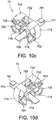
- the first outer housing 60 may be constructed of plastics by an injection molding process.
- the first outer housing 60 is hollow and extends lengthwise or axially.
- the first outer housing 60 has an accommodation room 615 defined by a top wall 611, a bottom wall 612, a right wall 613 and a left wall 614, wherein the top wall 611 faces the bottom wall 612 and connects with the right wall 613 and left wall 614.
- the accommodation room 615 has a front opening 617 and an opposed rear opening 618 in the lengthwise or axial direction.
- An engagement portion 621 is provided on the top wall 611.
- the engagement portion 621 may be a rectangular accommodation opening formed through the top wall 611 from inside to outside the accommodation room 615.
- a stop block 631 abuts the front edge of the top wall 611 and is located in front of the accommodation opening 621.
- a break 641 extends lengthwise through the stop block 631 and gradually becomes wider from the accommodation opening 621 to the front edge of the top wall 611 such that the accommodation opening 621 is in communication with the front edge of the top wall 611 through the break 641.
- an engagement portion 622 is provided on the bottom wall 612.
- the engagement portion 622 may be a rectangular accommodation opening formed through the bottom wall 612 from inside to outside the accommodation room 615.
- a stop block 632 abuts the front edge of the bottom wall 612 and is located in front of the accommodation opening 622.
- a break 642 extends lengthwise through the stop block 632 and gradually becomes wider from the accommodation opening 622 to the front edge of the bottom wall 612 such that the accommodation opening 622 is in communication with the front edge of the bottom wall 612 through the break 642.
- engagement portions 653 and 654 are respectively provided on the right wall 613 and the left wall 614.
- the respective engagement portions 653, 654 may be a projection, a slot or combinations thereof. Rectangular projections 661 and 662 are respectively provided on the top wall 611 and the bottom wall 612 within the accommodation room 615.
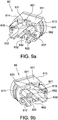
- the second outer housing 70 may be constructed of plastics by an injection molding process.
- the second outer housing 70 is hollow and extends lengthwise or axially.
- the second outer housing 70 has an accommodation room 715 defined by a top wall 711, a bottom wall 712, a right wall 713 and a left wall 714, wherein the top wall 711 faces the bottom wall 712 and connects with the right wall 713 and left wall 714.
- the accommodation room 715 has a front opening 717 and an opposed rear opening 718 in the lengthwise or axial direction.
- the top wall 711 is formed with a slot extending in the lengthwise or axial direction, which defines a rectangular break 761.
- An engagement arm 741 is formed within the break 761 and protrudes out of the break 761 in the axial direction from the top wall 711 toward the rear opening 718.
- An engagement portion 721 is provided on the rear end of the outer surface of the engagement arm 741 for engaging the engagement portion 621 or 622 of the first outer housing 60.
- the engagement portion 721 is an engagement projection for being positioned within the accommodation opening 621 or 622.
- the engagement projection 721 defines an angled or ramped outer surface, which is sloped down toward the rear end of the engagement arm 741.
- a press projection 751 is provided on the outer surface of the engagement arm 741. The press projection 751 extends lengthwise or axially from the engagement projection 721 and gradually becomes wider.
- Parts of the press projection 751 are positioned within the break 641 or 642.
- the bottom wall 712 is formed with a slot extending in the lengthwise or axial direction, which defines a rectangular break 762.
- An engagement arm 742 is formed within the break 762 and protrudes out of the break 762 in the axial direction from the bottom wall 712 toward the rear opening 718.
- An engagement portion 722 is provided on the rear end of the outer surface of the engagement arm 742 for engaging the engagement portion 621 or 622 of the first outer housing 60.
- the engagement portion 722 is an engagement projection for being positioned within the accommodation opening 621 or 622.
- the engagement projection 722 defines an angled or ramped outer surface, which is sloped down toward the rear end of the engagement arm 742.
- a press projection 752 is provided on the outer surface of the engagement arm 742.
- the press projection 752 extends lengthwise or axially from the engagement projection 722 and gradually becomes wider. Parts of the press projection 752 are positioned within the break 641 or 642.
- a key arm 771 extends from the top wall 711 lengthwise or axially and backward to the engagement arm 741.
- a restricting block 781 is provided on the inner surface of the key arm 771 for inserting into the grooves 521 and 522 on the inner housing 50 from the respective front edges thereof. The restricting block 781 may move lengthwise or axially in the grooves 521 and 522 but fails to be taken out directly upward from the groove 521 or 522.
- engagement portions 753 and 754 are respectively provided on the right wall 713 and the left wall 714.
- the respective engagement portions 753, 754 may be a projection, a slot or combinations thereof.
- the engagement portions 753 and 754 have shapes corresponding to respective shapes of the engagement portions 653 and 654 such that the engagement portions 753 and 754 may respectively engage the engagement portions 653 and 654.
- the engagement portions 753 and 754 have their shapes also corresponding to the respective shapes of the engagement portions 654 and 653 such that the engagement portions 753 and 754 may respectively engage the engagement portions 654 and 653.
- the flange 12 of the spring push 10 has a front end surface that is brought into contact with the rear end surface of the inner housing 50 according to the optical fiber connector of the present disclosure.
- the flexible arms 14 are inserted into the accommodation room 515 of the inner housing 50 from the rear opening 518 and the engagement protrusions 17 of the flexible arms 14 are brought into engagement with the respective engagement openings 516 accordingly.
- the spring push 10 comes in contact with the rear end 22 of the spring 20 with the forward portion 11 thereof and pushes the spring 20 forward toward the spring seat 30 to have the front end 21 of the spring 20 press upon the rear surface 32 of the spring seat 30.
- the guide pins 33 extending from the front surface 31 of the spring seat 30 are inserted into the respective holes 44 on the rear surface 42 of the ferrule 40.
- the ferrule 40 is pushed into the inner housing 50 by the spring 20 and the front surface 41 thereof protrudes from the front opening 517.
- the inner housing 50 is inserted into the accommodation room 615 of the first outer housing 60 from the rear opening 618 and protrudes from the front opening 617 such that the grooves 521 and 522 are exposed out of the first outer housing 60.
- the projections 661, 662 of the first outer housing 60 respectively slide on the ramped outer surfaces of the stop blocks 531, 532 on the inner housing 50.
- the projections 661, 662 finally move past the respective stop blocks 531, 532.
- the top wall 511 and bottom wall 512 of the inner housing 50 come to being positioned to directly face the top wall 611 and bottom wall 612 of the first outer housing 60 respectively.
- the second outer housing 70 is then coupled to the first outer housing 60.
- the inner housing 50 is inserted into the second outer housing 70 from the rear opening 718 and the engagement portions 721, 722 of the second outer housing 70 respectively engage the engagement portions 621, 622 of the first outer housing 60 and the engagement portions 753, 754 respectively engage the engagement portions 653, 654.
- the way to engage the engagement portion 721 with the engagement portion 621 is to press down the press projection 751 when the second outer housing 70 moves toward the first outer housing 60.
- the way to engage the engagement portion 722 with the engagement portion 622 is to press down the press projection 752 when the second outer housing 70 moves toward the first outer housing 60.
- the engagement portion 721 may slide on the outer surface of the top wall 511 and move through these two clearances when the press projection 751 is pressed down and the second outer housing 70 moves toward the first outer housing 60.
- parts of the press projections 751 and 752 of the second outer housing 70 are respectively positioned in the breaks 641 and 642. Furthermore, when the engagement portions 721, 722 respectively engage the engagement portions 621, 622, the engagement portions 753, 754 of the second outer housing 70 will respectively engage the engagement portions 653, 654 of the first outer housing 60.
- the restricting block 781 of the second outer housing 70 is inserted into the groove 521 on the inner housing 50 from its front edge.
- the key arm 771 is positioned on the top wall 511 of the inner housing 50 and above the groove 521 to function as the key protrusion accordingly.
- the key arm 771 on the inner housing 50 has the function the same as that of the key protrusion 112 of the connector 100a or 100b as illustrated in FIG. 1a or 1b .
- a ribbon fiber (not shown) may go through the spring push 10, spring 20 and spring seat 30 and then insert into the ferrule 40 from the opening 46.
- the bores 43 on the front surface 41 of the ferrule 40 receive the end portions of the respective optical fibers of the ribbon fiber and these end portions of the optical fibers are flush with the front surface 41 of the ferrule 40.
- the optical fiber connector 300 of the present disclosure may be inserted into a counterpart adapter and the counterpart adapter may be a known optical fiber adapter, for example, the optical fiber adapter 200 of FIG. 2 .
- the optical fiber connector 300 of the present disclosure may couple with another optical fiber connector of the same type, for example, the optical fiber connector 100a or 100b of FIG. 1a or 1b .
- the key arm 771 is arranged to be the key protrusion and therefore restrict the insertion of the optical fiber connector 300 into a counterpart adapter with only predetermined orientation.
- the optical fiber connector 300 of FIG. 3 fails to be inserted into the optical fiber adapter 200 from one of the openings 210 when the key arm 771 is positioned up.
- the key arm 771 may then be inserted into one of the key recesses 230 of the optical fiber adapter 200. Therefore, the optical fiber connector 300 may mate with the optical fiber adapter 200. This restricts the coupling of the optical fiber connector 300 and another optical fiber connector to the predetermined polarity.
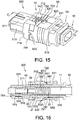
- the second outer housing 70 In order to switch or change the coupling polarity of the optical fiber connector 300, one presses down the press projections 751 and 752 of the second outer housing 70 and pull out the second outer housing 70. Afterward, the second outer housing 70 is turned over such that the key arm 771 is positioned down. The second outer housing 70 is then coupled to the first outer housing 60 to form the optical fiber connector 300 of FIG. 15 .
- the way to form the optical fiber connector 300 of FIG. 15 may refer to the above assembling steps given to form the optical fiber connector 300 of FIG. 13 . With reference to FIGS.
- the engagement projections 721, 722 respectively fall into the accommodation openings 622, 621 and the engagement portions 753, 754 respectively engage the engagement portions 654, 653 when the second outer housing 70 is coupled to the first outer housing 60.
- parts of the press projections 751 and 752 of the second outer housing 70 are respectively positioned in the breaks 642 and 641. This means that the engagement portions 721, 722 have engaged the respective engagement portions 622, 621 and the engagement portions 753, 754 have engaged the respective engagement portions 654, 653.
- the restricting block 781 of the second outer housing 70 is inserted into the groove 522 on the inner housing 50 from its front edge so that the key arm 771 is positioned on the bottom wall 512 of the inner housing 50 and above the groove 522 to function as the key protrusion. Accordingly, the coupling polarity of the optical fiber connector 300 is switched.
- the restricting block 781 fails to be removed directly upward from the groove 521 or 522. This prevents the key arm 771 from being raised from the top wall 511 or bottom wall 512 of the inner housing 50.
- the stop blocks 531, 532 of the inner housing 50 are positioned to restrict the respective movement of the projections 661, 662 of the first outer housing 60 further toward the front end of the inner housing 50. This prevents the first outer housing 60 from being pulled out from the front end of the inner housing 50.
- the stop blocks 631, 632 of the first outer housing 60 are positioned to stop the respective movement of the engagement projections 721, 722 of the second outer housing 70 when the engagement projections 721, 722 respectively engage the engagement portions 621, 622.
- optical fiber connector of the present disclosure may include other types of optical fiber connectors.
Landscapes
- Physics & Mathematics (AREA)
- General Physics & Mathematics (AREA)
- Optics & Photonics (AREA)
- Mechanical Coupling Of Light Guides (AREA)
Claims (4)
- Connecteur de fibre optique (300) à insérer dans un adaptateur de fibre optique (200) avec un évidement de clavette (230) formé en son sein, le connecteur de fibre optique (300) comprenant:un boîtier interne creux (50) ayant une première paroi (511), une deuxième paroi (513), une troisième paroi (512) et une quatrième paroi (514), dans lequel la première paroi (511) fait face à la troisième paroi (512) et est reliée aux deuxième et quatrième parois (513, 514);un premier boîtier externe (60) fixé au boîtier interne (50), le premier boîtier externe (60) ayant une pluralité de parois (611, 612, 613, 614), qui définissent une paroi supérieure (611), une paroi inférieure (612), une paroi droite (613) et une paroi gauche (614); etun second boîtier externe (70) couplé de manière détachable au premier boîtier externe (60) et fixé de manière détachable au boîtier interne (50), le second boîtier externe (70) comprenant un bras de clavette (771), dans lequel le second boîtier externe (70) est fixé de manière détachable au boîtier interne (50) en positionnant le bras de clavette (771) sélectivement sur la première paroi (511) dans un premier état en prise ou sur la troisième paroi (512) dans un second état en prise de telle sorte que le bras de clavette (771) est inséré dans l'évidement de clavette (230) lorsque le boîtier interne (50) est inséré dans l'adaptateur de fibre optique (200),dans lequel une première ouverture de réception (621) et une seconde ouverture de réception (622) sont respectivement formées sur la paroi supérieure (611) et la paroi inférieure (612) du premier boîter externe (60), dans lequel le second boîtier externe (70) comprend en outre un premier bras de mise en prise (741) et un second bras de mise en prise (742), une première saillie de mise en prise (721) étant couplée au premier bras de mise en prise (741) et une seconde saillie de mise en prise (722) étant couplée au second bras de mise en prise (742), dans lequel la première saillie de mise en prise (721) et la seconde saillie de mise en prise (722) sont configurées pour venir en prise avec la première ouverture de réception (621) ou la seconde ouverture de réception (622), caractérisé en ce quele premier boîtier externe (60) définit en outre un premier bloc d'arrêt (631) venant en butée contre un bord avant de la paroi supérieure (611) et situé devant la première ouverture de réception (621), dans lequel une première rupture (641) s'étend axialement à travers le premier bloc d'arrêt (631) et s'élargit progressivement à partir de la première ouverture de réception (621) jusqu'au bord avant de la paroi supérieure (611), de telle sorte que la première ouverture de réception (621) est en communication avec le bord avant de la paroi supérieure (611) à travers la première rupture (641), le premier boîtier externe (60) définit en outre un second bloc d'arrêt (632) venant en butée contre un bord avant de la paroi inférieure (612) et situé devant la seconde ouverture de réception (622), dans lequel une seconde rupture (642) s'étend axialement à travers le second bloc d'arrêt (632) et s'élargit progressivement à partir de la seconde ouverture de réception (622) jusqu'au bord avant de la paroi inférieure (612), de telle sorte que la seconde ouverture de réception (622) est en communication avec le bord avant de la paroi inférieure (612) à travers la seconde rupture (642), etdans lequel le premier bras de mise en prise (741) est en outre pourvu d'une première saillie d'appui (751) et le second bras de mise en prise (742) est en outre pourvu d'une seconde saillie d'appui (752), les première et seconde saillies d'appui (751, 752) étant configurées de telle sorte que des parties de celles-ci s'ajustent dans la rupture respective (641, 642),dans lequel, lorsque le second boîtier externe (70) et le premier boîtier externe (60) sont dans le premier état en prise, des parties des première et seconde saillies d'appui (751, 752) du second boîtier externe (70) sont positionnées respectivement dans les première et seconde ruptures (641, 642) sur le premier boîtier externe (60), les première et seconde saillies de mise en prise (721, 722) venant en prise respectivement avec les première et seconde ouvertures de réception (621, 622),et lorsque le second boîtier externe (70) et le premier boîtier externe (60) sont dans le second état de mise en prise, des parties des première et seconde saillies d'appui (751, 752) du second boîtier externe (70) sont positionnées respectivement dans les seconde et première ruptures (642, 641) sur le premier boîtier externe (60), les première et seconde saillies de mise en prise (721, 722) venant en prise respectivement avec les seconde et première ouvertures de réception (622, 621), et dans lequelles premier et second blocs d'arrêt (631, 632) sont positionnés pour arrêter des déplacements axiaux respectifs des première et seconde saillies de mise en prise (721, 722), en empêchant ainsi le second boîtier externe (70) de se détacher du premier boîtier externe (60), etdans lequel le second boîtier externe (70) peut être détaché du premier boîtier externe (60), lorsque les saillies d'appui (751, 752) sont appuyées vers le bas pour avoir le premier bras de mise en prise (741) et le second bras de mise en prise (742) pliés vers le boîtier interne (50).
- Connecteur de fibre optique (300) selon la revendication 1, dans lequel une rainure (521, 522) est formée sur chacune des première et troisième parois (511, 512), le second boîtier externe (70) comprend en outre un bloc de restriction (781) couplé au bras de clavette (771), la rainure respective (521, 522) est configurée pour recevoir le bloc de restriction (781) et empêcher le bloc de restriction (781) d'être soulevé à partir de la première paroi (511) ou de la troisième paroi (512).
- Connecteur de fibre optique (300) selon la revendication 1, dans lequel le boîtier interne (50) comprend en outre deux blocs d'arrêt (531, 532) positionnés respectivement sur la première paroi (511) et la troisième paroi (512) pour restreindre le déplacement du premier boîtier externe (60).
- Connecteur de fibre optique (300) selon la revendication 1, dans lequel le connecteur de fibre optique (300) est de type MPO.
Applications Claiming Priority (1)
| Application Number | Priority Date | Filing Date | Title |
|---|---|---|---|
| TW105139749A TWI618958B (zh) | 2016-12-01 | 2016-12-01 | 可改變對接極性之光纖連接器 |
Publications (2)
| Publication Number | Publication Date |
|---|---|
| EP3330757A1 EP3330757A1 (fr) | 2018-06-06 |
| EP3330757B1 true EP3330757B1 (fr) | 2021-01-13 |
Family
ID=58669678
Family Applications (1)
| Application Number | Title | Priority Date | Filing Date |
|---|---|---|---|
| EP17169350.0A Active EP3330757B1 (fr) | 2016-12-01 | 2017-05-03 | Connecteur de fibre optique pouvant commuter la polarité de connexion |
Country Status (4)
| Country | Link |
|---|---|
| US (1) | US9804340B1 (fr) |
| EP (1) | EP3330757B1 (fr) |
| JP (1) | JP6462060B2 (fr) |
| TW (1) | TWI618958B (fr) |
Families Citing this family (12)
| Publication number | Priority date | Publication date | Assignee | Title |
|---|---|---|---|---|
| WO2019079419A1 (fr) | 2017-10-18 | 2019-04-25 | Commscope Technologies Llc | Cassettes de connexion de fibres optiques |
| JP6543326B1 (ja) * | 2017-12-25 | 2019-07-10 | 株式会社フジクラ | 光コネクタ |
| US11256054B2 (en) | 2018-04-16 | 2022-02-22 | Commscope Technologies Llc | Adapter structure |
| US11041993B2 (en) * | 2018-04-19 | 2021-06-22 | Senko Advanced Components, Inc. | Fiber optic adapter with removable insert for polarity change and removal tool for the same |
| CN110609361B (zh) * | 2018-09-30 | 2025-06-10 | 中航光电科技股份有限公司 | 一种缩短型mpo光纤连接器 |
| US11099330B2 (en) | 2018-12-06 | 2021-08-24 | Senko Advanced Components, Inc. | Ultra-small form factor optical connectors with polarity change and method of use |
| US11422312B2 (en) | 2019-05-09 | 2022-08-23 | Commscope Technologies Llc | Fiber optic converter |
| TWM584438U (zh) * | 2019-07-03 | 2019-10-01 | 建毅科技股份有限公司 | 光纖連接器 |
| USD970447S1 (en) * | 2019-10-24 | 2022-11-22 | 3P Design | Optical fiber connector |
| USD942955S1 (en) * | 2019-12-19 | 2022-02-08 | Corning Research & Development Corporation | Cap for an adapter |
| TWM615335U (zh) * | 2020-09-23 | 2021-08-11 | 建毅科技股份有限公司 | 光纖連接器 |
| JP2024519197A (ja) * | 2021-04-21 | 2024-05-09 | コーニング リサーチ アンド ディヴェロップメント コーポレイション | 一体型導波路と光ファイバとの位置合わせのためのシステム、装置、及び方法 |
Family Cites Families (14)
| Publication number | Priority date | Publication date | Assignee | Title |
|---|---|---|---|---|
| US9720183B2 (en) * | 2009-08-24 | 2017-08-01 | Panduit Corp. | Fiber optic adapter with enhanced alignment |
| US8651749B2 (en) * | 2010-03-19 | 2014-02-18 | Corning Incorporated | Fiber optic interface with translatable ferrule device |
| JP5439319B2 (ja) * | 2010-09-06 | 2014-03-12 | 株式会社フジクラ | 光コネクタおよび光コネクタの挿抜方法 |
| US8636424B2 (en) * | 2010-10-22 | 2014-01-28 | Panduit Corp. | Optical communication connector |
| CN104272153A (zh) * | 2012-03-01 | 2015-01-07 | 蒂科电子公司 | 用于mpo系统的键控 |
| US8770863B2 (en) * | 2012-06-04 | 2014-07-08 | Corning Cable Systems Llc | Multi-fiber fiber-optic connector with switchable polarity key |
| GB2506884B (en) * | 2012-10-10 | 2017-04-12 | Fibrefab Ltd | Fibre optic connector device |
| US9423570B2 (en) * | 2013-02-05 | 2016-08-23 | Commscope Technologies Llc | Optical assemblies with managed connectivity |
| MX2016000475A (es) * | 2013-07-16 | 2016-04-07 | 3M Innovative Properties Co | Conector para cubiertas de telecomunicaciones. |
| US10067301B2 (en) * | 2014-01-13 | 2018-09-04 | Commscope Connectivity Uk Limited | Fiber optic connector |
| TWI483021B (zh) * | 2014-06-10 | 2015-05-01 | Oe Tek Inc | MPO fiber optic adapter |
| EP3161536A4 (fr) * | 2014-06-27 | 2018-01-03 | ADC Telecommunications Inc. | Terminaux d'indexation pour la prise en charge d'une architecture d'indexation bidirectionnelle |
| TWI518393B (zh) * | 2015-02-24 | 2016-01-21 | 楊沐晨 | 可交換對接極性之單件式光纖適配器 |
| US9658409B2 (en) * | 2015-03-03 | 2017-05-23 | Senko Advanced Components, Inc. | Optical fiber connector with changeable polarity |
-
2016
- 2016-12-01 TW TW105139749A patent/TWI618958B/zh active
-
2017
- 2017-03-23 US US15/467,249 patent/US9804340B1/en active Active
- 2017-05-03 EP EP17169350.0A patent/EP3330757B1/fr active Active
- 2017-07-14 JP JP2017137834A patent/JP6462060B2/ja active Active
Non-Patent Citations (1)
| Title |
|---|
| None * |
Also Published As
| Publication number | Publication date |
|---|---|
| TWI618958B (zh) | 2018-03-21 |
| JP6462060B2 (ja) | 2019-01-30 |
| EP3330757A1 (fr) | 2018-06-06 |
| TW201821842A (zh) | 2018-06-16 |
| JP2018092126A (ja) | 2018-06-14 |
| US9804340B1 (en) | 2017-10-31 |
Similar Documents
| Publication | Publication Date | Title |
|---|---|---|
| EP3330757B1 (fr) | Connecteur de fibre optique pouvant commuter la polarité de connexion | |
| US8641293B2 (en) | Optical fiber connector and apparatus of facilitating to pull out optical fiber connector | |
| EP3327476B1 (fr) | Adaptateur de fibre optique ayant des éléments d'obturation | |
| EP3367146B1 (fr) | Adaptateur de fibre optique ayant des éléments d'obturation | |
| US10120138B2 (en) | Connector with trigger locking feature, and cable assemblies and methods including the same | |
| US11774685B2 (en) | Adapter for optical connectors | |
| EP3414608B1 (fr) | Connecteur de fibres optiques à ferrules multifibres, et ensembles de câbles et systèmes en comportant | |
| US9632256B2 (en) | Optical fiber adapter with shutter member | |
| EP1731937B1 (fr) | Système de connecteurs avec manchon de verrouillage secondaire pour la connection des connecteurs | |
| CN208125956U (zh) | 光纤连接器和光纤电缆组件 | |
| EP3151045B1 (fr) | Adaptateur de fibre optique avec élément d'obturation | |
| TWI518393B (zh) | 可交換對接極性之單件式光纖適配器 | |
| US10416394B2 (en) | Fiber optic receptacle with integrated device therein | |
| WO2008029850A1 (fr) | Connecteur optique | |
| US9146363B2 (en) | Optical fiber adapter with shutter member | |
| JP6543326B1 (ja) | 光コネクタ | |
| US12449610B2 (en) | Multi-fiber reusable splicing systems | |
| CN108614328B (zh) | 可改变对接极性的光纤连接器 | |
| WO2003076973A2 (fr) | Adaptateur monobloc |
Legal Events
| Date | Code | Title | Description |
|---|---|---|---|
| PUAI | Public reference made under article 153(3) epc to a published international application that has entered the european phase |
Free format text: ORIGINAL CODE: 0009012 |
|
| STAA | Information on the status of an ep patent application or granted ep patent |
Free format text: STATUS: REQUEST FOR EXAMINATION WAS MADE |
|
| 17P | Request for examination filed |
Effective date: 20180316 |
|
| AK | Designated contracting states |
Kind code of ref document: A1 Designated state(s): AL AT BE BG CH CY CZ DE DK EE ES FI FR GB GR HR HU IE IS IT LI LT LU LV MC MK MT NL NO PL PT RO RS SE SI SK SM TR |
|
| AX | Request for extension of the european patent |
Extension state: BA ME |
|
| STAA | Information on the status of an ep patent application or granted ep patent |
Free format text: STATUS: EXAMINATION IS IN PROGRESS |
|
| 17Q | First examination report despatched |
Effective date: 20191114 |
|
| GRAP | Despatch of communication of intention to grant a patent |
Free format text: ORIGINAL CODE: EPIDOSNIGR1 |
|
| STAA | Information on the status of an ep patent application or granted ep patent |
Free format text: STATUS: GRANT OF PATENT IS INTENDED |
|
| INTG | Intention to grant announced |
Effective date: 20200720 |
|
| GRAS | Grant fee paid |
Free format text: ORIGINAL CODE: EPIDOSNIGR3 |
|
| GRAA | (expected) grant |
Free format text: ORIGINAL CODE: 0009210 |
|
| STAA | Information on the status of an ep patent application or granted ep patent |
Free format text: STATUS: THE PATENT HAS BEEN GRANTED |
|
| AK | Designated contracting states |
Kind code of ref document: B1 Designated state(s): AL AT BE BG CH CY CZ DE DK EE ES FI FR GB GR HR HU IE IS IT LI LT LU LV MC MK MT NL NO PL PT RO RS SE SI SK SM TR |
|
| REG | Reference to a national code |
Ref country code: GB Ref legal event code: FG4D |
|
| REG | Reference to a national code |
Ref country code: CH Ref legal event code: EP |
|
| REG | Reference to a national code |
Ref country code: IE Ref legal event code: FG4D |
|
| REG | Reference to a national code |
Ref country code: DE Ref legal event code: R096 Ref document number: 602017031270 Country of ref document: DE |
|
| REG | Reference to a national code |
Ref country code: AT Ref legal event code: REF Ref document number: 1354993 Country of ref document: AT Kind code of ref document: T Effective date: 20210215 |
|
| REG | Reference to a national code |
Ref country code: CH Ref legal event code: NV Representative=s name: LANGPATENT ANWALTSKANZLEI IP LAW FIRM, CH |
|
| REG | Reference to a national code |
Ref country code: AT Ref legal event code: MK05 Ref document number: 1354993 Country of ref document: AT Kind code of ref document: T Effective date: 20210113 |
|
| REG | Reference to a national code |
Ref country code: NL Ref legal event code: MP Effective date: 20210113 |
|
| REG | Reference to a national code |
Ref country code: LT Ref legal event code: MG9D |
|
| PG25 | Lapsed in a contracting state [announced via postgrant information from national office to epo] |
Ref country code: LT Free format text: LAPSE BECAUSE OF FAILURE TO SUBMIT A TRANSLATION OF THE DESCRIPTION OR TO PAY THE FEE WITHIN THE PRESCRIBED TIME-LIMIT Effective date: 20210113 Ref country code: BG Free format text: LAPSE BECAUSE OF FAILURE TO SUBMIT A TRANSLATION OF THE DESCRIPTION OR TO PAY THE FEE WITHIN THE PRESCRIBED TIME-LIMIT Effective date: 20210413 Ref country code: GR Free format text: LAPSE BECAUSE OF FAILURE TO SUBMIT A TRANSLATION OF THE DESCRIPTION OR TO PAY THE FEE WITHIN THE PRESCRIBED TIME-LIMIT Effective date: 20210414 Ref country code: FI Free format text: LAPSE BECAUSE OF FAILURE TO SUBMIT A TRANSLATION OF THE DESCRIPTION OR TO PAY THE FEE WITHIN THE PRESCRIBED TIME-LIMIT Effective date: 20210113 Ref country code: HR Free format text: LAPSE BECAUSE OF FAILURE TO SUBMIT A TRANSLATION OF THE DESCRIPTION OR TO PAY THE FEE WITHIN THE PRESCRIBED TIME-LIMIT Effective date: 20210113 Ref country code: PT Free format text: LAPSE BECAUSE OF FAILURE TO SUBMIT A TRANSLATION OF THE DESCRIPTION OR TO PAY THE FEE WITHIN THE PRESCRIBED TIME-LIMIT Effective date: 20210513 Ref country code: NO Free format text: LAPSE BECAUSE OF FAILURE TO SUBMIT A TRANSLATION OF THE DESCRIPTION OR TO PAY THE FEE WITHIN THE PRESCRIBED TIME-LIMIT Effective date: 20210413 |
|
| PG25 | Lapsed in a contracting state [announced via postgrant information from national office to epo] |
Ref country code: SE Free format text: LAPSE BECAUSE OF FAILURE TO SUBMIT A TRANSLATION OF THE DESCRIPTION OR TO PAY THE FEE WITHIN THE PRESCRIBED TIME-LIMIT Effective date: 20210113 Ref country code: AT Free format text: LAPSE BECAUSE OF FAILURE TO SUBMIT A TRANSLATION OF THE DESCRIPTION OR TO PAY THE FEE WITHIN THE PRESCRIBED TIME-LIMIT Effective date: 20210113 Ref country code: LV Free format text: LAPSE BECAUSE OF FAILURE TO SUBMIT A TRANSLATION OF THE DESCRIPTION OR TO PAY THE FEE WITHIN THE PRESCRIBED TIME-LIMIT Effective date: 20210113 Ref country code: PL Free format text: LAPSE BECAUSE OF FAILURE TO SUBMIT A TRANSLATION OF THE DESCRIPTION OR TO PAY THE FEE WITHIN THE PRESCRIBED TIME-LIMIT Effective date: 20210113 Ref country code: RS Free format text: LAPSE BECAUSE OF FAILURE TO SUBMIT A TRANSLATION OF THE DESCRIPTION OR TO PAY THE FEE WITHIN THE PRESCRIBED TIME-LIMIT Effective date: 20210113 |
|
| PG25 | Lapsed in a contracting state [announced via postgrant information from national office to epo] |
Ref country code: IS Free format text: LAPSE BECAUSE OF FAILURE TO SUBMIT A TRANSLATION OF THE DESCRIPTION OR TO PAY THE FEE WITHIN THE PRESCRIBED TIME-LIMIT Effective date: 20210513 |
|
| REG | Reference to a national code |
Ref country code: DE Ref legal event code: R097 Ref document number: 602017031270 Country of ref document: DE |
|
| PG25 | Lapsed in a contracting state [announced via postgrant information from national office to epo] |
Ref country code: CZ Free format text: LAPSE BECAUSE OF FAILURE TO SUBMIT A TRANSLATION OF THE DESCRIPTION OR TO PAY THE FEE WITHIN THE PRESCRIBED TIME-LIMIT Effective date: 20210113 Ref country code: EE Free format text: LAPSE BECAUSE OF FAILURE TO SUBMIT A TRANSLATION OF THE DESCRIPTION OR TO PAY THE FEE WITHIN THE PRESCRIBED TIME-LIMIT Effective date: 20210113 Ref country code: SM Free format text: LAPSE BECAUSE OF FAILURE TO SUBMIT A TRANSLATION OF THE DESCRIPTION OR TO PAY THE FEE WITHIN THE PRESCRIBED TIME-LIMIT Effective date: 20210113 |
|
| PLBE | No opposition filed within time limit |
Free format text: ORIGINAL CODE: 0009261 |
|
| STAA | Information on the status of an ep patent application or granted ep patent |
Free format text: STATUS: NO OPPOSITION FILED WITHIN TIME LIMIT |
|
| PG25 | Lapsed in a contracting state [announced via postgrant information from national office to epo] |
Ref country code: DK Free format text: LAPSE BECAUSE OF FAILURE TO SUBMIT A TRANSLATION OF THE DESCRIPTION OR TO PAY THE FEE WITHIN THE PRESCRIBED TIME-LIMIT Effective date: 20210113 Ref country code: RO Free format text: LAPSE BECAUSE OF FAILURE TO SUBMIT A TRANSLATION OF THE DESCRIPTION OR TO PAY THE FEE WITHIN THE PRESCRIBED TIME-LIMIT Effective date: 20210113 Ref country code: SK Free format text: LAPSE BECAUSE OF FAILURE TO SUBMIT A TRANSLATION OF THE DESCRIPTION OR TO PAY THE FEE WITHIN THE PRESCRIBED TIME-LIMIT Effective date: 20210113 |
|
| 26N | No opposition filed |
Effective date: 20211014 |
|
| PG25 | Lapsed in a contracting state [announced via postgrant information from national office to epo] |
Ref country code: ES Free format text: LAPSE BECAUSE OF FAILURE TO SUBMIT A TRANSLATION OF THE DESCRIPTION OR TO PAY THE FEE WITHIN THE PRESCRIBED TIME-LIMIT Effective date: 20210113 Ref country code: AL Free format text: LAPSE BECAUSE OF FAILURE TO SUBMIT A TRANSLATION OF THE DESCRIPTION OR TO PAY THE FEE WITHIN THE PRESCRIBED TIME-LIMIT Effective date: 20210113 Ref country code: LU Free format text: LAPSE BECAUSE OF NON-PAYMENT OF DUE FEES Effective date: 20210503 Ref country code: MC Free format text: LAPSE BECAUSE OF FAILURE TO SUBMIT A TRANSLATION OF THE DESCRIPTION OR TO PAY THE FEE WITHIN THE PRESCRIBED TIME-LIMIT Effective date: 20210113 |
|
| REG | Reference to a national code |
Ref country code: BE Ref legal event code: MM Effective date: 20210531 |
|
| PG25 | Lapsed in a contracting state [announced via postgrant information from national office to epo] |
Ref country code: SI Free format text: LAPSE BECAUSE OF FAILURE TO SUBMIT A TRANSLATION OF THE DESCRIPTION OR TO PAY THE FEE WITHIN THE PRESCRIBED TIME-LIMIT Effective date: 20210113 |
|
| PG25 | Lapsed in a contracting state [announced via postgrant information from national office to epo] |
Ref country code: IT Free format text: LAPSE BECAUSE OF FAILURE TO SUBMIT A TRANSLATION OF THE DESCRIPTION OR TO PAY THE FEE WITHIN THE PRESCRIBED TIME-LIMIT Effective date: 20210113 Ref country code: IE Free format text: LAPSE BECAUSE OF NON-PAYMENT OF DUE FEES Effective date: 20210503 |
|
| PG25 | Lapsed in a contracting state [announced via postgrant information from national office to epo] |
Ref country code: IS Free format text: LAPSE BECAUSE OF FAILURE TO SUBMIT A TRANSLATION OF THE DESCRIPTION OR TO PAY THE FEE WITHIN THE PRESCRIBED TIME-LIMIT Effective date: 20210513 Ref country code: FR Free format text: LAPSE BECAUSE OF NON-PAYMENT OF DUE FEES Effective date: 20210531 |
|
| PG25 | Lapsed in a contracting state [announced via postgrant information from national office to epo] |
Ref country code: BE Free format text: LAPSE BECAUSE OF NON-PAYMENT OF DUE FEES Effective date: 20210531 |
|
| PG25 | Lapsed in a contracting state [announced via postgrant information from national office to epo] |
Ref country code: NL Free format text: LAPSE BECAUSE OF NON-PAYMENT OF DUE FEES Effective date: 20210113 Ref country code: CY Free format text: LAPSE BECAUSE OF FAILURE TO SUBMIT A TRANSLATION OF THE DESCRIPTION OR TO PAY THE FEE WITHIN THE PRESCRIBED TIME-LIMIT Effective date: 20210113 |
|
| PG25 | Lapsed in a contracting state [announced via postgrant information from national office to epo] |
Ref country code: HU Free format text: LAPSE BECAUSE OF FAILURE TO SUBMIT A TRANSLATION OF THE DESCRIPTION OR TO PAY THE FEE WITHIN THE PRESCRIBED TIME-LIMIT; INVALID AB INITIO Effective date: 20170503 |
|
| PG25 | Lapsed in a contracting state [announced via postgrant information from national office to epo] |
Ref country code: MK Free format text: LAPSE BECAUSE OF FAILURE TO SUBMIT A TRANSLATION OF THE DESCRIPTION OR TO PAY THE FEE WITHIN THE PRESCRIBED TIME-LIMIT Effective date: 20210113 |
|
| PG25 | Lapsed in a contracting state [announced via postgrant information from national office to epo] |
Ref country code: MT Free format text: LAPSE BECAUSE OF FAILURE TO SUBMIT A TRANSLATION OF THE DESCRIPTION OR TO PAY THE FEE WITHIN THE PRESCRIBED TIME-LIMIT Effective date: 20210113 |
|
| PGFP | Annual fee paid to national office [announced via postgrant information from national office to epo] |
Ref country code: DE Payment date: 20250521 Year of fee payment: 9 |
|
| PGFP | Annual fee paid to national office [announced via postgrant information from national office to epo] |
Ref country code: GB Payment date: 20250417 Year of fee payment: 9 |
|
| PGFP | Annual fee paid to national office [announced via postgrant information from national office to epo] |
Ref country code: CH Payment date: 20250830 Year of fee payment: 9 |
|
| PG25 | Lapsed in a contracting state [announced via postgrant information from national office to epo] |
Ref country code: TR Free format text: LAPSE BECAUSE OF FAILURE TO SUBMIT A TRANSLATION OF THE DESCRIPTION OR TO PAY THE FEE WITHIN THE PRESCRIBED TIME-LIMIT Effective date: 20210113 |