EP3330843A1 - Verfahren, vorrichtung und fernbedienung zur steuerung eines projektionscursors - Google Patents
Verfahren, vorrichtung und fernbedienung zur steuerung eines projektionscursors Download PDFInfo
- Publication number
- EP3330843A1 EP3330843A1 EP15882431.8A EP15882431A EP3330843A1 EP 3330843 A1 EP3330843 A1 EP 3330843A1 EP 15882431 A EP15882431 A EP 15882431A EP 3330843 A1 EP3330843 A1 EP 3330843A1
- Authority
- EP
- European Patent Office
- Prior art keywords
- projection screen
- remote controller
- visible light
- displacement
- cursor
- Prior art date
- Legal status (The legal status is an assumption and is not a legal conclusion. Google has not performed a legal analysis and makes no representation as to the accuracy of the status listed.)
- Withdrawn
Links
Images

Classifications
-
- G—PHYSICS
- G06—COMPUTING OR CALCULATING; COUNTING
- G06F—ELECTRIC DIGITAL DATA PROCESSING
- G06F3/00—Input arrangements for transferring data to be processed into a form capable of being handled by the computer; Output arrangements for transferring data from processing unit to output unit, e.g. interface arrangements
- G06F3/01—Input arrangements or combined input and output arrangements for interaction between user and computer
- G06F3/03—Arrangements for converting the position or the displacement of a member into a coded form
- G06F3/033—Pointing devices displaced or positioned by the user, e.g. mice, trackballs, pens or joysticks; Accessories therefor
- G06F3/0346—Pointing devices displaced or positioned by the user, e.g. mice, trackballs, pens or joysticks; Accessories therefor with detection of the device orientation or free movement in a three-dimensional [3D] space, e.g. 3D mice, 6-DOF [six degrees of freedom] pointers using gyroscopes, accelerometers or tilt-sensors
-
- G—PHYSICS
- G06—COMPUTING OR CALCULATING; COUNTING
- G06F—ELECTRIC DIGITAL DATA PROCESSING
- G06F3/00—Input arrangements for transferring data to be processed into a form capable of being handled by the computer; Output arrangements for transferring data from processing unit to output unit, e.g. interface arrangements
- G06F3/01—Input arrangements or combined input and output arrangements for interaction between user and computer
- G06F3/03—Arrangements for converting the position or the displacement of a member into a coded form
- G06F3/033—Pointing devices displaced or positioned by the user, e.g. mice, trackballs, pens or joysticks; Accessories therefor
- G06F3/038—Control and interface arrangements therefor, e.g. drivers or device-embedded control circuitry
-
- G—PHYSICS
- G06—COMPUTING OR CALCULATING; COUNTING
- G06F—ELECTRIC DIGITAL DATA PROCESSING
- G06F3/00—Input arrangements for transferring data to be processed into a form capable of being handled by the computer; Output arrangements for transferring data from processing unit to output unit, e.g. interface arrangements
- G06F3/01—Input arrangements or combined input and output arrangements for interaction between user and computer
- G06F3/048—Interaction techniques based on graphical user interfaces [GUI]
- G06F3/0484—Interaction techniques based on graphical user interfaces [GUI] for the control of specific functions or operations, e.g. selecting or manipulating an object, an image or a displayed text element, setting a parameter value or selecting a range
Definitions
- the present disclosure relates to the field of communications, and particularly to a projection cursor control method and device and a remote controller.
- a user if a user is positioned in the vicinity of projection source equipment supporting a touch screen operation, the user, when needing to operate a projected picture, may touch a screen of the projection source equipment to change a position of a cursor.
- the user if the user is at a certain distance from the projection source equipment, the user is still possible to change the position of the cursor by virtue of a mouse.
- a plane for placing the mouse may be needed. If there is no proper plane, it may be impossible to precisely move the cursor by using the mouse.
- a Bluetooth remote controller may be adopted to change a position of a cursor.
- Bluetooth remote controllers in the related technology are able to change a position of a cursor only by virtue of a key.
- keys for four directions e.g., up, down, left and right may be provided on the Bluetooth remote controller. If a key for a direction is pressed once or for a certain period of time, the cursor may be controlled to move to the corresponding direction for a number of cells (for example, a cell may represent a half of a character width).
- a cursor movement distance represented by each key pressing is set to be excessively short, the user may need to frequently press the key in order to move the cursor for a relatively long distance. If the cursor movement distance represented by each key pressing is set to be excessively long, the user may be unable to control the cursor to move precisely, thereby bringing inconvenience especially under a scenario where the cursor movement distance needs to meet a certain precision requirement.
- Some embodiments of the present disclosure provide a projection cursor control method and device and a remote controller, which may at least solve a problem that a Bluetooth remote controller may not control a cursor to move precisely in the related technology.
- a projection cursor control method may include the following acts.
- a turning angle of a remote controller may be acquired.
- a displacement of a light spot formed on a projection screen by projecting visible light emitted by a visible light emitter of the remote controller may be calculated based on the turning angle and a spatial position relationship between the remote controller and the projection screen.
- a cursor position represented by a current projection position of the light spot on the projection screen may be determined based on the displacement, a pixel width, represented by a horizontal displacement of a unit length on the projection screen, in a horizontal direction and a pixel height, represented by a vertical displacement of the unit length on the projection screen, in a vertical direction, and the cursor position may include a pixel position in the horizontal direction and a pixel position in the vertical direction.
- a cursor in a picture projected on the projection screen may be moved to the cursor position.
- the method may further include the following acts. Under a circumstance that the light spot formed on the projection screen by projecting the visible light emitted by the visible light emitter is overlapped with at least three calibration points projected on the projection screen respectively, a distance between each calibration point in the at least three calibration points and the remote controller and an angle between each calibration point in the at least three calibration points and the visible light emitted by the visible light emitter may be acquired, herein the at least three calibration points may not be on a same straight line.
- the spatial position relationship between the remote controller and the projection screen may be determined based on the acquired distance and angle.
- the method may further include the following act.
- the pixel width, represented by the horizontal displacement of the unit length on the projection screen, in the horizontal direction and the pixel height, represented by the vertical displacement of the unit length on the projection screen, in the vertical direction may be determined based on the spatial position relationship.
- the distance between each calibration point in the at least three calibration points and the remote controller may be acquired in the following manner.
- the distance between each calibration point in the at least three calibration points and the remote controller may be detected through a distance detector on the remote controller.
- the angle between each calibration point in the at least three calibration points and the visible light emitted by the visible light emitter may be acquired in a following manner.
- An angle change of the remote controller may be detected through a sensor on the remote controller, the sensor may include: a gravity sensor and/or a gyroscope sensor.
- the angle between each calibration point in the at least three calibration points and the visible light emitted by the visible light emitter may be calculated based on an initial angle of the visible light emitted by the visible light emitter and the angle change.
- the pixel width, represented by the horizontal displacement of the unit length on the projection screen, in the horizontal direction and the pixel height, represented by the vertical displacement of the unit length on the projection screen, in the vertical direction may be determined based on the spatial position relationship in a following manner. A distance between every two calibration points in the at least three calibration points may be calculated based on the spatial position relationship.
- the pixel width, represented by the horizontal displacement of the unit length on the projection screen, in the horizontal direction and the pixel height, represented by the vertical displacement of the unit length on the projection screen, in the vertical direction may be determined based on a pixel width and pixel height between every two calibration points in the three calibration points and the distance between every two calibration points in the at least three calibration points.
- a projection cursor control device may include a first acquisition module, a calculation module, a first determination module and a movement module.
- the first acquisition module may be configured to acquire a turning angle of a remote controller.
- the calculation module may be configured to calculate a displacement of a light spot formed on a projection screen by projecting visible light emitted by a visible light emitter of the remote controller based on the turning angle and a spatial position relationship between the remote controller and the projection screen.
- the first determination module may be configured to determine a cursor position represented by a current projection position of the light spot on the projection screen based on the displacement, a pixel width, represented by a horizontal displacement of a unit length on the projection screen, in a horizontal direction and a pixel height, represented by a vertical displacement of the unit length on the projection screen, in a vertical direction, wherein the cursor position may include a pixel position in the horizontal direction and a pixel position in the vertical direction.
- the movement module may be configured to move a cursor in a picture projected on the projection screen to the cursor position.
- the device may further include a second acquisition module and a second determination module.
- the second acquisition module may be configured to, under a circumstance that the light spot formed on the projection screen by projecting the visible light emitted by the visible light emitter is overlapped with at least three calibration points projected on the projection screen respectively, acquire a distance between each calibration point in the at least three calibration points and the remote controller and acquire an angle between each calibration point in the at least three calibration points and the visible light emitted by the visible light emitter, wherein the at least three calibration points may not be on a same straight line.
- the second determination module may be configured to determine the spatial position relationship between the remote controller and the projection screen based on the acquired distance and angle.
- the device may further include a third determination module.
- the third determination module may be configured to determine the pixel width, represented by the horizontal displacement of the unit length on the projection screen, in the horizontal direction and the pixel height, represented by the vertical displacement of the unit length on the projection screen, in the vertical direction based on the spatial position relationship.
- a remote controller may include a distance detector, a sensor, a visible light emitter, a signal transceiver and a processor.
- the distance detector, the sensor, the visible light emitter and the signal transceiver may be connected with the processor respectively.
- the sensor may be configured to acquire a turning angle of the remote controller.
- the sensor and the distance detector may further be configured to acquire a spatial position relationship between the remote controller and a projection screen.
- the visible light emitter may be configured to emit visible light to project a light spot on the projection screen;
- the processor may be configured to calculate, based on the turning angle and the spatial position relationship between the remote controller and the projection screen, a displacement of the light spot formed on the projection screen by projecting the visible light emitted by the visible light emitter of the remote controller.
- the processor may further be configured to determine a cursor position represented by a current projection position of the light spot on the projection screen based on the displacement, a pixel width, represented by a horizontal displacement of a unit length on the projection screen, in a horizontal direction and a pixel height, represented by a vertical displacement of the unit length on the projection screen, in a vertical direction, wherein the cursor position may include a pixel position in the horizontal direction and a pixel position in the vertical direction.
- the signal transceiver may be configured to send the cursor position to a projection source to enable the projection source to move a cursor in a picture projected on the projection screen to the cursor position.
- a turning angle of a remote controller may be acquired.
- a displacement of a light spot formed on a projection screen by projecting a visible light emitted by a visible light emitter of the remote controller may be calculated based on the turning angle and the spatial position relationship between the remote controller and the projection screen.
- a cursor position represented by a current projection position of the light spot on the projection screen may be determined based on the displacement, a pixel width, represented by a horizontal displacement of a unit length on the projection screen, in a horizontal direction and a pixel height, represented by a vertical displacement of a unit length on the projection screen, in a vertical direction, wherein the cursor position may include the pixel position in the horizontal direction and the pixel position in the vertical direction.
- a cursor in a picture projected on the projection screen may be moved to the cursor position.
- FIG. 1 is a flowchart of a projection cursor control method according to an embodiment of the present disclosure. As shown in Fig. 1 , the flow may include the following acts.
- a turning angle of a remote controller may be acquired.
- a displacement of a light spot formed on a projection screen by projecting visible light emitted by a visible light emitter of the remote controller may be calculated based on the turning angle and a spatial position relationship between the remote controller and the projection screen.
- a cursor position represented by a current projection position of the light spot on the projection screen may be determined based on the displacement, a pixel width, represented by a horizontal displacement of a unit length on the projection screen, in a horizontal direction and a pixel height, represented by a vertical displacement of the unit length on the projection screen, in a vertical direction.
- the cursor position may include a pixel position in the horizontal direction and a pixel position in the vertical direction.
- a cursor in a picture projected on the projection screen may be moved to the cursor position.
- the displacement of the light spot emitted by the remote controller on the projection screen may be calculated based on the turning angle of the remote controller.
- the cursor position represented by the current projection position on the projection screen may be determined in combination with the pixel width, represented by the horizontal displacement of the unit length on the projection screen, in the horizontal direction and the pixel height, represented by the vertical displacement of the unit length on the projection screen, in the vertical direction.
- the turning angle of the remote controller and the cursor position are mapped, so that a pixel width and pixel height for movement of the cursor may directly be calculated based on the turning angle of the remote controller under a circumstance that a position of the remote controller is kept unchanged.
- angle control of the user over the remote controller is higher in precision, and may provide a more convenient and intuitive operation experience for the user.
- pixel-level movement precision may completely meet a high-precision cursor movement requirement.
- the method may be implemented through the remote controller, and may alternatively be implemented by cooperation of the remote controller and other equipment.
- the remote controller may acquire needed parameters (for example, information about a distance and angle between the remote controller and the projection screen) and send these parameters to the other equipment for processing, and the cursor position may be determined and changed through the other equipment.
- needed parameters for example, information about a distance and angle between the remote controller and the projection screen
- the cursor position may be determined and changed through the other equipment.
- the spatial position relationship between the remote controller and the projection screen may be determined. Determination of the spatial position relationship may be implemented by calibration. For example, under a circumstance that the light spot formed on the projection screen by projecting the visible light emitted by the visible light emitter is overlapped with at least three calibration points projected on the projection screen respectively, a distance between each calibration point in the at least three calibration points and the remote controller and an angle between each calibration point in the at least three calibration points and the visible light emitted by the visible light emitter may be acquired.
- the at least three calibration points are not on a same straight line.
- the spatial position relationship between the remote controller and the projection screen may be determined based on the acquired distance and angle. After the spatial position relationship is determined, a spatial geometric model may be established, and then related parameters which may subsequently be utilized may be calculated by virtue of the spatial geometric model.
- the pixel width represented by the horizontal displacement of the unit length on the projection screen, in the horizontal direction
- the pixel height represented by the vertical displacement of the unit length on the projection screen, in the vertical direction
- the distance between each calibration point in the at least three calibration points and the remote controller may be acquired in a following manner.
- the distance between each calibration point in the at least three calibration points and the remote controller may be detected through a distance detector on the remote controller.
- the angle between each calibration point in the at least three calibration points and the visible light emitted by the visible light emitter may be acquired in a following manner.
- An angle change of the remote controller may be detected through a sensor on the remote controller, wherein the sensor may include a gravity sensor and/or a gyroscope sensor.
- the angle between each calibration point in the at least three calibration points and the visible light emitted by the visible light emitter may be calculated based on an initial angle of the visible light emitted by the visible light emitter and the angle change.
- the pixel width, represented by the horizontal displacement of the unit length on the projection screen, in the horizontal direction and the pixel height, represented by the vertical displacement of the unit length on the projection screen, in the vertical direction may be determined based on the spatial position relationship in the following manner. A distance between every two calibration points in the at least three calibration points may be calculated based on the spatial position relationship.
- the pixel width, represented by the horizontal displacement of the unit length on the projection screen, in the horizontal direction and the pixel height, represented by the vertical displacement of the unit length on the projection screen, in the vertical direction may be determined based on a pixel width and pixel height between every two calibration points in the three calibration points and the distance between every two calibration points in the at least three calibration points.
- the method for calculating the related parameters by virtue of the spatial geometric model directs to a mathematical problem about spatial geometry, and feasibility in calculation of the related parameters can be proved.
- a manner for solving the related parameters is not limited, and the following are merely exemplary descriptions.
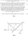
- Fig. 2 is a schematic diagram of determining a pixel position of a cursor based on a turning angle of a remote controller according to an embodiment of the present disclosure.
- an X axis represents a horizontal direction
- a Y axis represents a vertical direction
- X, Y and Z axes are perpendicular to each other.
- a quadrangle OABC represents a projection screen
- D, E and F represent three calibration points respectively
- a point R is a position of the remote controller.
- RD, RE and RF represent visible light emitted by a visible light emitter, their respective distances may be detected through a distance detector, ⁇ DRE, ⁇ ERF and ⁇ FRD may be detected through a sensor respectively.
- ⁇ DRE distance detector
- ⁇ ERF distance detector
- ⁇ FRD distance detector
- ⁇ ERD distance detector
- ⁇ ERF distance detector
- ⁇ FRD sensor
- a pixel width between DE is known to be, for example, a 1,000-pixel width, that is, there are totally 1,000 pixels in the horizontal direction from the point D to the point E. If a pointing direction of the remote controller (i.e.
- a direction of the light emitted by the visible light emitter, represented as a light spot on the projection screen) turns from pointing to the point D to pointing to a point H
- a turning angle is ZDRH.
- a length of DH may be calculated based on the turning angle.
- a pixel width from the point H to the point D may be calculated based on a ratio of DH to DE, thereby determining a cursor position of the point H. For example, when the point H is a midpoint of DE, the cursor position represented by the point H is a position after the point D moves rightwards for a 500-pixel width.
- angle numerical values of ⁇ DRH and ⁇ ERH may be unequal.
- corresponding pixel widths or pixel heights
- the acquired angle is suggested to be represented in a vector manner.
- the computer software product may be stored in a storage medium (for example, a Read-Only Memory (ROM)/Random Access Memory (RAM), a magnetic disk and an optical disk), including a plurality of instructions configured to enable a piece of terminal equipment (which may be a mobile phone, a computer, a server, network equipment or the like) to execute the method of each embodiment of the present disclosure.
- a storage medium for example, a Read-Only Memory (ROM)/Random Access Memory (RAM), a magnetic disk and an optical disk
- a piece of terminal equipment which may be a mobile phone, a computer, a server, network equipment or the like
- An embodiment provides a projection cursor control device.
- the device may be configured to implement the abovementioned embodiment and exemplary implementation modes, and what has been described will not be elaborated.
- term "module”, used below, may be a combination of software and/or hardware capable of realizing a preset function.
- the device described in the following embodiment is preferably implemented with software, implementation with hardware or a combination of the software and the hardware is also possible and conceivable.
- Fig. 3 is a structure block diagram of a projection cursor control device according to an embodiment of the present disclosure.
- the device may include a first acquisition module 32, a calculation module 34, a first determination module 36 and a movement module 38.
- the first acquisition module 32 may be configured to acquire a turning angle of a remote controller.
- the calculation module 34 may be coupled to the first acquisition module 32, and may be configured to calculate, based on the turning angle and a spatial position relationship between the remote controller and a projection screen, a displacement of a light spot formed on the projection screen by projecting visible light emitted by a visible light emitter of the remote controller.
- the first determination module 36 may be coupled to the calculation module 34, and may be configured to determine a cursor position represented by a current projection position of the light spot on the projection screen based on the displacement, a pixel width, represented by a horizontal displacement of a unit length on the projection screen, in a horizontal direction and a pixel height, represented by a vertical displacement of the unit length on the projection screen, in a vertical direction.
- the cursor position may include a pixel position in the horizontal direction and a pixel position in the vertical direction.
- the movement module 38 may be coupled to the first determination module 36, and may be configured to move a cursor in a picture projected on the projection screen to the cursor position.
- the device may further include a second acquisition module and a second determination module.
- the second acquisition module may be configured to, under a circumstance that the light spot formed on the projection screen by projecting the visible light emitted by the visible light emitter is overlapped with at least three calibration points projected on the projection screen respectively, acquire a distance between each calibration point in the at least three calibration points and the remote controller and an angle between each calibration point in the at least three calibration points and the visible light emitted by the visible light emitter.
- the at least three calibration points are not on a same straight line.
- the second determination module may be coupled to the second acquisition module and the calculation module 34 and configured to determine the spatial position relationship between the remote controller and the projection screen based on the acquired distance and angle.
- the device may further include a third determination module.
- the third determination module may be coupled to the first determination module 36 and configured to determine the pixel width, represented by the horizontal displacement of the unit length on the projection screen, in the horizontal direction and the pixel height, represented by the vertical displacement of the unit length on the projection screen, in the vertical direction based on the spatial position relationship.
- Another embodiment of the present disclosure provides a remote controller, which may be configured to implement the projection cursor control method.
- Fig. 4 is a structure diagram of a remote controller according to an embodiment of the present disclosure.
- the remote controller may include a distance detector 40, a sensor 42, a visible light emitter 44, a signal transceiver 46 and a processor 48.
- the distance detector 40, the sensor 42, the visible light emitter 44 and the signal transceiver 46 may be connected with the processor 48 respectively.
- the sensor 42 may be configured to acquire a turning angle of the remote controller.
- the sensor 42 and the distance detector 40 may be further configured to acquire a spatial position relationship between the remote controller and a projection screen.
- the visible light emitter 44 may be configured to emit visible light to project a light spot on the projection screen.
- the processor 48 may be configured to calculate, based on the turning angle and the spatial position relationship between the remote controller and the projection screen, a displacement of the light spot formed on the projection screen by projecting the visible light emitted by the visible light emitter of the remote controller.
- the processor 48 may be further configured to determine a cursor position represented by a current projection position of the light spot on the projection screen based on the displacement, a pixel width, represented by a horizontal displacement of a unit length on the projection screen, in a horizontal direction and a pixel height, represented by a vertical displacement of the unit length on the projection screen, in a vertical direction.
- the cursor position may include a pixel position in the horizontal direction and a pixel position in the vertical direction.
- the signal transceiver 46 may be configured to send the cursor position to a projection source to enable the projection source to move a cursor in a picture projected on the projection screen to the cursor position.
- each of the modules may be implemented through software or hardware, and the latter may be implemented in, but not limited to, the following manner. All of the modules may be located in the same processor, or, the modules may be located in multiple processors respectively.
- Still another embodiment of the present disclosure provides software, which may be configured to execute the technical solutions described in the embodiments and preferred implementation modes.
- Still another embodiment of the present disclosure provides a storage medium.
- the storage medium may be configured to store program codes configured to execute the following acts.
- a turning angle of a remote controller may be acquired.
- a displacement of a light spot formed on a projection screen by projecting visible light emitted by a visible light emitter of the remote controller may be calculated based on the turning angle and a spatial position relationship between the remote controller and the projection screen.
- a cursor position represented by a current projection position of the light spot on the projection screen may be determined based on the displacement, a pixel width, represented by a horizontal displacement of a unit length on the projection screen, in a horizontal direction and a pixel height, represented by a vertical displacement of the unit length on the projection screen, in a vertical direction.
- the cursor position may include a pixel position in the horizontal direction and a pixel position in the vertical direction.
- a cursor in a picture projected on the projection screen may be moved to the cursor position.
- the storage medium may include, but not limited to: various media capable of storing program codes such as a U disk, a ROM, a RAM, a mobile hard disk, a magnetic disk or an optical disk.
- Examples in the embodiment may refer to examples described in the abovementioned embodiments and exemplary implementation modes, and will not be elaborated in the embodiment.
- a Bluetooth remote controller refers to a remote controller of which a signal transceiver device is a Bluetooth device.
- the Bluetooth remote controller may implement communication between the remote controller and projection equipment in a Bluetooth transmission manner, and may also transmit a key value of a key of the remote controller to the projection equipment to enable the projection equipment to complete a certain operation.
- a laser indicator (equivalent to the abovementioned visible light emitter) may be integrated to a front end of the Bluetooth remote controller.
- the laser indicator also called as a laser pen, is a pen type emitter which is designed to emit visible laser light, is portable and easy to handhold and is machined from a laser module (light-emitting diode).
- the laser indicator is usually used by a reporter, a teacher or a tour guide for projecting a light spot or a beam to point to an object.
- the Bluetooth remote controller of the exemplary embodiment of the present disclosure there is also a built-in gyroscope (equivalent to the abovementioned sensor) capable of measuring a horizontal or vertical movement angle of the device.
- a built-in gyroscope (equivalent to the abovementioned sensor) capable of measuring a horizontal or vertical movement angle of the device.
- a distance sensor (equivalent to the abovementioned distance detector) is also integrated to a front end.
- a coordinate calculation unit, a cursor movement unit, an angle processing unit and a calibration module may also be deployed for cooperative work in the exemplary embodiment of the present disclosure.
- the coordinate calculation unit, the cursor movement unit, the angle processing unit and the calibration module may be located in the Bluetooth remote controller, and may alternatively be located in a projector. The locations of these units are not limited in the embodiment of the present disclosure.
- An existing Bluetooth remote controller with an integrated gyroscope may be applied to a television, and does not have a calibration function. Since a distance between a user and the television is limited and the television may be operated within a small range, there may not be a big error.
- the solution proposes a process of calibration before use, and precision may be enhanced after the calibration.
- a projection cursor control method provided by the exemplary embodiment of the present disclosure may include the following acts.
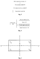
- FIG. 5 is a schematic diagram of a calibration method according to an exemplary embodiment of the present disclosure. As shown in Fig. 5 , the calibration method is as follows.
- Four points may be determined on a screen.
- the user respectively points to each point in a calibration process, and meanwhile longitudinal and transverse turning angles of the Bluetooth remote controller may be acquired through a gyroscope device arranged in the Bluetooth remote controller respectively.
- a distance to each point may be detected through the distance sensor.
- a spatial geometric model configured to calculate a turning angle and a displacement of a light spot on the screen may be established based on the acquired angles and distances.
- distances between the four points may further be calculated based on the spatial geometric model, and then a relationship between a turning angle of the Bluetooth remote controller and a pixel distance may be calculated based on the pixel distances between the four points.
- Fig. 6 is a schematic diagram of user position change according to an exemplary embodiment of the present disclosure.
- the user may turn the remote controller by X degrees if he operates the laser indicator of the remote controller to make the light spot move from the point D to the point C.
- the user may turn the remote controller by Y degrees if he operates the laser indicator of the remote controller to make the light spot move from the point D to the point C.
- it may be known that, although values of X and Y are different, a movement distance of light spot projected by the laser indicator on the projection screen is the same. Therefore, it can be seen that, after the position of the user is changed, the corresponding relationship between the turning angle of the Bluetooth remote controller and the pixel distance of the cursor may be changed. Therefore, after the position of the user is changed, recalibration is suggested.
- Fig. 7 is a flowchart of a projection cursor control method according to an exemplary embodiment of the present disclosure. As shown in Fig. 7 , the method may include the following acts.
- the projector starts projecting a picture.
- a cursor and a coordinate are determined based on a deflection angle.
- angle information may be transmitted by virtue of communication between the Bluetooth remote controller and equipment, and the angle and the coordinate may be calculated by the equipment.
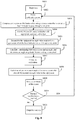
- Fig. 8 is an optional flowchart of a projection cursor control method according to an exemplary embodiment of the present disclosure. As shown in Fig. 8 , the optional flow may include the following acts.
- the projector is fixed at a position, and starts projection.
- the Bluetooth remote controller is paired with the projector, and starts calibration.
- the OK button of the remote controller is pressed every time when the laser indicator passes through a point.
- the angle processing unit calculates a relationship between a pixel and a movement angle, and determines a movement angle N° corresponding to one pixel.
- each time when the movement angle exceeds N the remote controller transmits an angle value to the angle processing unit of the equipment.
- the cursor movement unit determines a coordinate, to which the cursor needs to be moved, based on the changed angle value.
- act S810 whether recalibration of the user is required or not is judged. If the user clicks a recalibration button, act S802 is automatically executed for recalibration.
- the user may place the projector at any posture, after a power supply is switched on and a projection switch is turned on, projector cursor calibration may be started after the projector enters a stable state, and after calibration, the user may remotely and precisely move the cursor only with the remote controller.
- the displacement of the light spot emitted by the remote controller on the projection screen may be calculated based on the turning angle of the remote controller. Furthermore, the cursor position represented by the current projection position on the projection screen may be determined based on the pixel width, represented by the horizontal displacement of the unit length on the projection screen, in the horizontal direction and the pixel height, represented by the vertical displacement of the unit length on the projection screen, in the vertical direction.
- the turning angle of the remote controller and the cursor position are mapped, so that the pixel width and pixel height for movement of the cursor may directly be calculated based on the turning angle of the remote controller under a circumstance that the position of the remote controller is kept unchanged.
- angle control of the user over the remote controller is higher in precision, and may provide a more convenient and intuitive operation experience for the user.
- pixel-level movement precision may completely meet a high-precision cursor movement requirement.
- each module or each step of the present disclosure may be implemented by a universal computing device, and the modules or acts may be concentrated on a single computing device or distributed on a network formed by a plurality of computing devices, and may optionally be implemented by program codes executable for the computing devices, so that the modules or acts may be stored in a storage device for execution with the computing devices, the shown or described acts may be executed in sequences different from those described here in some circumstances, or may form each integrated circuit module respectively, or multiple modules or acts therein may form a single integrated circuit module for implementation.
- the present disclosure is not limited to any specific hardware and software combination.
Landscapes
- Engineering & Computer Science (AREA)
- General Engineering & Computer Science (AREA)
- Theoretical Computer Science (AREA)
- Human Computer Interaction (AREA)
- Physics & Mathematics (AREA)
- General Physics & Mathematics (AREA)
- Position Input By Displaying (AREA)
- Projection Apparatus (AREA)
Applications Claiming Priority (2)
| Application Number | Priority Date | Filing Date | Title |
|---|---|---|---|
| CN201510456605.6A CN106406570A (zh) | 2015-07-29 | 2015-07-29 | 投影光标控制方法、装置及遥控器 |
| PCT/CN2015/092229 WO2016131292A1 (zh) | 2015-07-29 | 2015-10-19 | 投影光标控制方法、装置及遥控器 |
Publications (2)
| Publication Number | Publication Date |
|---|---|
| EP3330843A1 true EP3330843A1 (de) | 2018-06-06 |
| EP3330843A4 EP3330843A4 (de) | 2018-07-18 |
Family
ID=56688692
Family Applications (1)
| Application Number | Title | Priority Date | Filing Date |
|---|---|---|---|
| EP15882431.8A Withdrawn EP3330843A4 (de) | 2015-07-29 | 2015-10-19 | Verfahren, vorrichtung und fernbedienung zur steuerung eines projektionscursors |
Country Status (4)
| Country | Link |
|---|---|
| US (1) | US20190012002A1 (de) |
| EP (1) | EP3330843A4 (de) |
| CN (1) | CN106406570A (de) |
| WO (1) | WO2016131292A1 (de) |
Cited By (1)
| Publication number | Priority date | Publication date | Assignee | Title |
|---|---|---|---|---|
| CN112283622A (zh) * | 2020-11-17 | 2021-01-29 | 厦门金尼申科技有限公司 | 一种具有蓝牙控制灯光照射角度的追光灯 |
Families Citing this family (10)
| Publication number | Priority date | Publication date | Assignee | Title |
|---|---|---|---|---|
| CN107193397A (zh) * | 2017-05-11 | 2017-09-22 | 广州视源电子科技股份有限公司 | 一种指向型设备的定位装置 |
| CN107274750A (zh) * | 2017-06-13 | 2017-10-20 | 苏州佳世达电通有限公司 | 指标校正方法及指标校正系统 |
| CN108415562A (zh) * | 2018-02-12 | 2018-08-17 | 四川斐讯信息技术有限公司 | 一种光标控制方法及系统 |
| CN111352544A (zh) * | 2018-12-21 | 2020-06-30 | 北京科加触控技术有限公司 | 一种屏幕指示标识移动调整方法、装置及系统 |
| CN111462248B (zh) * | 2020-03-13 | 2024-05-14 | 中天智领(北京)科技有限公司 | 一种用于屏幕交互中光标位置校准参数标定方法及装置 |
| CN111462247B (zh) * | 2020-03-13 | 2024-04-02 | 中天智领(北京)科技有限公司 | 一种用于屏幕交互的光标位置校准方法及装置 |
| CN112565866B (zh) * | 2020-11-30 | 2023-12-05 | 深圳创维-Rgb电子有限公司 | 焦点控制方法、系统、设备及存储介质 |
| CN114257850A (zh) * | 2021-12-23 | 2022-03-29 | 四川长虹电器股份有限公司 | 遥控显示屏中光标的方法 |
| CN115580715B (zh) * | 2022-09-01 | 2025-07-25 | 深圳市康帕斯科技发展有限公司 | 投影画面自动矫正的方法和系统 |
| CN119342258B (zh) * | 2023-07-21 | 2025-11-04 | 华为技术有限公司 | 一种光标位置确定方法和遥控设备 |
Family Cites Families (22)
| Publication number | Priority date | Publication date | Assignee | Title |
|---|---|---|---|---|
| US6373961B1 (en) * | 1996-03-26 | 2002-04-16 | Eye Control Technologies, Inc. | Eye controllable screen pointer |
| US6104380A (en) * | 1997-04-14 | 2000-08-15 | Ricoh Company, Ltd. | Direct pointing apparatus for digital displays |
| US20040095317A1 (en) * | 2002-11-20 | 2004-05-20 | Jingxi Zhang | Method and apparatus of universal remote pointing control for home entertainment system and computer |
| WO2005099253A1 (en) * | 2004-04-08 | 2005-10-20 | Koninklijke Philips Electronics N.V. | Mobile projectable gui |
| US7683881B2 (en) * | 2004-05-24 | 2010-03-23 | Keytec, Inc. | Visual input pointing device for interactive display system |
| WO2005119356A2 (en) * | 2004-05-28 | 2005-12-15 | Erik Jan Banning | Interactive direct-pointing system and calibration method |
| US7796116B2 (en) * | 2005-01-12 | 2010-09-14 | Thinkoptics, Inc. | Electronic equipment for handheld vision based absolute pointing system |
| US20080180395A1 (en) * | 2005-03-04 | 2008-07-31 | Gray Robert H | Computer pointing input device |
| US9285897B2 (en) * | 2005-07-13 | 2016-03-15 | Ultimate Pointer, L.L.C. | Easily deployable interactive direct-pointing system and calibration method therefor |
| US8144123B2 (en) * | 2007-08-14 | 2012-03-27 | Fuji Xerox Co., Ltd. | Dynamically controlling a cursor on a screen when using a video camera as a pointing device |
| CA2721073A1 (en) * | 2008-04-10 | 2009-10-15 | Karl Christopher Hansen | Simple-to-use optical wireless remote control |
| CN101859192A (zh) * | 2009-04-09 | 2010-10-13 | 鸿富锦精密工业(深圳)有限公司 | 计算机控制系统及方法 |
| KR20120058802A (ko) * | 2010-11-30 | 2012-06-08 | 삼성전자주식회사 | 3차원 위치/방향 추정 시스템에서 3차원 위치를 보정하는 장치 및 방법 |
| CN106959770A (zh) * | 2011-03-28 | 2017-07-18 | 曦恩体感科技股份有限公司 | 3d指示装置与补偿3d指示装置的转动的方法 |
| CN102508565B (zh) * | 2011-11-17 | 2014-06-25 | Tcl集团股份有限公司 | 遥控器光标定位方法、装置、遥控器及光标定位系统 |
| US9927876B2 (en) * | 2012-09-28 | 2018-03-27 | Movea | Remote control with 3D pointing and gesture recognition capabilities |
| US20140097250A1 (en) * | 2012-10-04 | 2014-04-10 | Thomas Charles Antognini | Variable formatting of digital data into a pattern |
| CN103823617B (zh) * | 2012-11-19 | 2016-08-24 | 原相科技股份有限公司 | 互动系统及遥控装置 |
| US9804689B2 (en) * | 2013-02-19 | 2017-10-31 | Pixart Imaging Inc. | Handheld pointer device and pointer positioning method thereof |
| US10067576B2 (en) * | 2013-02-19 | 2018-09-04 | Pixart Imaging Inc. | Handheld pointer device and tilt angle adjustment method thereof |
| TWI489324B (zh) * | 2013-07-05 | 2015-06-21 | Pixart Imaging Inc | 手持式指向裝置的游標定位方法 |
| US20160334884A1 (en) * | 2013-12-26 | 2016-11-17 | Interphase Corporation | Remote Sensitivity Adjustment in an Interactive Display System |
-
2015
- 2015-07-29 CN CN201510456605.6A patent/CN106406570A/zh active Pending
- 2015-10-19 US US15/745,198 patent/US20190012002A1/en not_active Abandoned
- 2015-10-19 EP EP15882431.8A patent/EP3330843A4/de not_active Withdrawn
- 2015-10-19 WO PCT/CN2015/092229 patent/WO2016131292A1/zh not_active Ceased
Cited By (1)
| Publication number | Priority date | Publication date | Assignee | Title |
|---|---|---|---|---|
| CN112283622A (zh) * | 2020-11-17 | 2021-01-29 | 厦门金尼申科技有限公司 | 一种具有蓝牙控制灯光照射角度的追光灯 |
Also Published As
| Publication number | Publication date |
|---|---|
| WO2016131292A1 (zh) | 2016-08-25 |
| EP3330843A4 (de) | 2018-07-18 |
| CN106406570A (zh) | 2017-02-15 |
| US20190012002A1 (en) | 2019-01-10 |
Similar Documents
| Publication | Publication Date | Title |
|---|---|---|
| EP3330843A1 (de) | Verfahren, vorrichtung und fernbedienung zur steuerung eines projektionscursors | |
| US11934086B2 (en) | Method and device for adjusting projected image | |
| US11951637B2 (en) | Calibration apparatus and calibration method for coordinate system of robotic arm | |
| US10598479B2 (en) | Three-dimensional measuring device removably coupled to robotic arm on motorized mobile platform | |
| JP7345042B2 (ja) | 移動ロボットのナビゲーション | |
| US10415950B2 (en) | Metrology device and method of performing an inspection | |
| US9739591B2 (en) | Metrology device and method of initiating communication | |
| US20190347927A1 (en) | Device and method for controlling a plurality of targeted devices | |
| US10639795B2 (en) | Light spot indication robot and light spot indication method thereof | |
| US20140104169A1 (en) | Method for Determining the Relative Position of an Object in an Area, and Optical Input System | |
| US8358268B2 (en) | Multi-touch detection | |
| US12309535B2 (en) | Projection device for displaying construction plans | |
| JP2013544382A (ja) | 移動ロボット | |
| EP4177837B1 (de) | Markerdetektionsvorrichtung und roboterlernsystem | |
| JP2021030371A (ja) | ロボットシステムおよび制御方法 | |
| CN107037807A (zh) | 自移动机器人位姿校准系统和方法 | |
| EP2607841A2 (de) | Optisches System | |
| CN117260776A (zh) | 一种应用于机器人的人机交互方法及装置 | |
| US9465486B2 (en) | Portable interactive whiteboard module | |
| KR102858425B1 (ko) | 장치와 함께 운반 가능한 센서를 사용한 로컬화 | |
| KR20170140009A (ko) | 비콘태그를 이용한 측정장치 | |
| US20240210173A1 (en) | Target and Plumbing System for Transferring a Point of Interest on a Jobsite Surface | |
| JP2015123560A (ja) | ロボットシステム、ロボット制御装置、及びロボット制御方法 | |
| US20220234612A1 (en) | Location indicator devices | |
| KR101304407B1 (ko) | 원격 마우스의 레이저 포인팅 위치를 추정하기 위한 장치 및 그 방법 |
Legal Events
| Date | Code | Title | Description |
|---|---|---|---|
| PUAI | Public reference made under article 153(3) epc to a published international application that has entered the european phase |
Free format text: ORIGINAL CODE: 0009012 |
|
| 17P | Request for examination filed |
Effective date: 20180125 |
|
| AK | Designated contracting states |
Kind code of ref document: A1 Designated state(s): AL AT BE BG CH CY CZ DE DK EE ES FI FR GB GR HR HU IE IS IT LI LT LU LV MC MK MT NL NO PL PT RO RS SE SI SK SM TR |
|
| AX | Request for extension of the european patent |
Extension state: BA ME |
|
| A4 | Supplementary search report drawn up and despatched |
Effective date: 20180615 |
|
| RIC1 | Information provided on ipc code assigned before grant |
Ipc: G06F 3/0346 20130101ALI20180611BHEP Ipc: G06F 3/0484 20130101AFI20180611BHEP |
|
| DAV | Request for validation of the european patent (deleted) | ||
| DAX | Request for extension of the european patent (deleted) | ||
| STAA | Information on the status of an ep patent application or granted ep patent |
Free format text: STATUS: THE APPLICATION HAS BEEN WITHDRAWN |
|
| 18W | Application withdrawn |
Effective date: 20181217 |