EP3330954A2 - Afficheur et son procédé d'affichage - Google Patents
Afficheur et son procédé d'affichage Download PDFInfo
- Publication number
- EP3330954A2 EP3330954A2 EP17199107.8A EP17199107A EP3330954A2 EP 3330954 A2 EP3330954 A2 EP 3330954A2 EP 17199107 A EP17199107 A EP 17199107A EP 3330954 A2 EP3330954 A2 EP 3330954A2
- Authority
- EP
- European Patent Office
- Prior art keywords
- display
- barrier
- driver unit
- panel
- instruction
- Prior art date
- Legal status (The legal status is an assumption and is not a legal conclusion. Google has not performed a legal analysis and makes no representation as to the accuracy of the status listed.)
- Ceased
Links
Images


Classifications
-
- G—PHYSICS
- G09—EDUCATION; CRYPTOGRAPHY; DISPLAY; ADVERTISING; SEALS
- G09G—ARRANGEMENTS OR CIRCUITS FOR CONTROL OF INDICATING DEVICES USING STATIC MEANS TO PRESENT VARIABLE INFORMATION
- G09G3/00—Control arrangements or circuits, of interest only in connection with visual indicators other than cathode-ray tubes
- G09G3/20—Control arrangements or circuits, of interest only in connection with visual indicators other than cathode-ray tubes for presentation of an assembly of a number of characters, e.g. a page, by composing the assembly by combination of individual elements arranged in a matrix no fixed position being assigned to or needed to be assigned to the individual characters or partial characters
-
- G—PHYSICS
- G09—EDUCATION; CRYPTOGRAPHY; DISPLAY; ADVERTISING; SEALS
- G09G—ARRANGEMENTS OR CIRCUITS FOR CONTROL OF INDICATING DEVICES USING STATIC MEANS TO PRESENT VARIABLE INFORMATION
- G09G5/00—Control arrangements or circuits for visual indicators common to cathode-ray tube indicators and other visual indicators
- G09G5/36—Control arrangements or circuits for visual indicators common to cathode-ray tube indicators and other visual indicators characterised by the display of a graphic pattern, e.g. using an all-points-addressable [APA] memory
- G09G5/38—Control arrangements or circuits for visual indicators common to cathode-ray tube indicators and other visual indicators characterised by the display of a graphic pattern, e.g. using an all-points-addressable [APA] memory with means for controlling the display position
-
- G—PHYSICS
- G06—COMPUTING OR CALCULATING; COUNTING
- G06F—ELECTRIC DIGITAL DATA PROCESSING
- G06F21/00—Security arrangements for protecting computers, components thereof, programs or data against unauthorised activity
- G06F21/70—Protecting specific internal or peripheral components, in which the protection of a component leads to protection of the entire computer
- G06F21/82—Protecting input, output or interconnection devices
- G06F21/84—Protecting input, output or interconnection devices output devices, e.g. displays or monitors
-
- G—PHYSICS
- G06—COMPUTING OR CALCULATING; COUNTING
- G06V—IMAGE OR VIDEO RECOGNITION OR UNDERSTANDING
- G06V20/00—Scenes; Scene-specific elements
- G06V20/50—Context or environment of the image
- G06V20/59—Context or environment of the image inside of a vehicle, e.g. relating to seat occupancy, driver state or inner lighting conditions
-
- G—PHYSICS
- G06—COMPUTING OR CALCULATING; COUNTING
- G06V—IMAGE OR VIDEO RECOGNITION OR UNDERSTANDING
- G06V40/00—Recognition of biometric, human-related or animal-related patterns in image or video data
- G06V40/10—Human or animal bodies, e.g. vehicle occupants or pedestrians; Body parts, e.g. hands
- G06V40/18—Eye characteristics, e.g. of the iris
- G06V40/19—Sensors therefor
-
- G—PHYSICS
- G09—EDUCATION; CRYPTOGRAPHY; DISPLAY; ADVERTISING; SEALS
- G09G—ARRANGEMENTS OR CIRCUITS FOR CONTROL OF INDICATING DEVICES USING STATIC MEANS TO PRESENT VARIABLE INFORMATION
- G09G5/00—Control arrangements or circuits for visual indicators common to cathode-ray tube indicators and other visual indicators
- G09G5/003—Details of a display terminal, the details relating to the control arrangement of the display terminal and to the interfaces thereto
-
- G—PHYSICS
- G09—EDUCATION; CRYPTOGRAPHY; DISPLAY; ADVERTISING; SEALS
- G09G—ARRANGEMENTS OR CIRCUITS FOR CONTROL OF INDICATING DEVICES USING STATIC MEANS TO PRESENT VARIABLE INFORMATION
- G09G2310/00—Command of the display device
- G09G2310/08—Details of timing specific for flat panels, other than clock recovery
-
- G—PHYSICS
- G09—EDUCATION; CRYPTOGRAPHY; DISPLAY; ADVERTISING; SEALS
- G09G—ARRANGEMENTS OR CIRCUITS FOR CONTROL OF INDICATING DEVICES USING STATIC MEANS TO PRESENT VARIABLE INFORMATION
- G09G2320/00—Control of display operating conditions
- G09G2320/02—Improving the quality of display appearance
- G09G2320/028—Improving the quality of display appearance by changing the viewing angle properties, e.g. widening the viewing angle, adapting the viewing angle to the view direction
-
- G—PHYSICS
- G09—EDUCATION; CRYPTOGRAPHY; DISPLAY; ADVERTISING; SEALS
- G09G—ARRANGEMENTS OR CIRCUITS FOR CONTROL OF INDICATING DEVICES USING STATIC MEANS TO PRESENT VARIABLE INFORMATION
- G09G2354/00—Aspects of interface with display user
-
- G—PHYSICS
- G09—EDUCATION; CRYPTOGRAPHY; DISPLAY; ADVERTISING; SEALS
- G09G—ARRANGEMENTS OR CIRCUITS FOR CONTROL OF INDICATING DEVICES USING STATIC MEANS TO PRESENT VARIABLE INFORMATION
- G09G2358/00—Arrangements for display data security
Definitions
- the present disclosure relates to image displaying technology, and more particularly to a display device and display method thereof.
- Display device is one of the most common input or output electronic devices. Display device is configured to display text, images, and videos.
- Contemporary display device usually has a wide viewing angle screen. Its visible angle of view can be as wide as from approximately 120 to 170 degree. When users use these devices in bus, subway, or other crowded public places, the content on the screen can be easily exposed and visible to other people around, which may lead to serious privacy leaks.
- the embodiments of the present disclosure provide a display device and display method thereof, as follows:
- a display device includes: a control unit, a display driver unit and a barrier driver unit which are connected to the control unit, a display panel which is connected to the display driver unit and a barrier panel.
- the barrier panel is disposed above the display panel and connected to the barrier driver unit.
- the barrier panel includes a plurality of display barriers which are parallel and distributed adjacently in the barrier panel.
- the control unit is used to send an image frame to the display driver unit and send a first instruction to the barrier driver unit;
- the display driver unit is used to drive the display panel to display the image frame on a plurality of display areas which are parallel and distributed at intervals. Each individual display area is used to display the corresponding portion of the image frame;
- the barrier driver unit is used to turn on the electrodes of the display barriers at the odd or even number positions in the barrier panel according to the first instruction.
- the display barrier When the electrode of the display barrier is in an on state, the display barrier will block light; when it is in an off state, the display barrier will allow light to pass through.
- Each display area displays its corresponding content.
- the content can pass through the display barrier whose electrode is in an on state in the barrier panel and is cast within the predetermined visible range.
- control unit can also be used to send a second instruction to the barrier driver unit;
- the electrode of each display barrier can be turned on according to the second instruction by the barrier driver unit.
- the control unit sends a third instruction corresponding to the first instruction to the display driver unit;
- the display driver unit can be used to determine the positions of the display areas which are parallel and distributed at intervals on the display panel according to the third instruction, disassemble the image frame and obtain the corresponding display content for each individual display area, and drive each individual display area to display its corresponding content according to its position.
- the third instruction is used to determine the position of each display area;
- the control unit is able to determine the position of each display area according to the distance between user's two eyes, the coordinates of user eyes projected on the barrier panel, the distance between user eyes and the barrier panel, and the distance between the barrier panel and the display panel.
- the electrodes of the display barriers in the barrier panel at odd number positions are connected to a first signal line; the electrodes of the display barriers in the barrier panel at even number positions are connected to a second signal line.
- a display method is provided and applied to the above display device.
- the display device comprises: a control unit, a display driver unit and a barrier driver unit which are connected to the control unit, a display panel which is connected to the display driver unit, a barrier panel which is located above the display panel and connected to the barrier driver unit, and a plurality of display barriers which are parallel and distributed adjacently in the barrier panel.
- the control unit sends an image frame to the display driver unit and a first instruction to the barrier driver unit;
- the display driver unit drives the display panel to display the image frame on the display areas which are parallel and distributed at intervals. Each individual display area is used to display its corresponding portion of the image frame;
- the barrier driver unit turns on the electrode of the display barrier which is located at either odd or even number position in the barrier panel.
- the electrode of a display barrier is in an on state, the display barriers are used to block light; when it is in an off state, the display barriers are used to allow light to pass through;
- Each display area displays its corresponding content that passes through the display barrier whose electrode is in an on state and is cast within the predetermined visible range.
- the method further comprising:
- the display driver unit determines the positions of display areas which are the parallel and distributed at intervals on the display panel; The display driver unit disassembles the image frame and obtains the corresponding display content for each individual display area; The display driver unit drives each display area to display its corresponding content according to its position.
- the third instruction is used to determine the position of each display area.
- the method further comprising:
- the method further comprising:
- the control unit sends the first instruction to the barrier driver unit.
- the barrier driver unit turns on the electrode of the display barrier in the barrier panel at either odd number position or even number position to block light.
- the control unit sends the image frame to the display driver unit.
- Display driver unit drives the display panel to display the image frame on the display areas which are parallel and distributed at intervals. Every display area is used to display its corresponding portion of the image frame.
- the content passes through the display barrier whose electrode is in an on state and is cast within the predetermined visible range; because a portion of display barriers in the barrier panel block light, users can only see the image frame within the predetermined visible range through the display barriers whose electrodes are in an off state.
- a display device with a relative narrow viewing angle and a display method are provided by the embodiments of the present disclosure, wherein the display device can be any kind of electronic devices with a display screen, such as mobile phones, tablets, etc.
- Fig. 1 is a block diagram of a display device 100 shown in accordance with an exemplary embodiment.
- the viewing angle of display device 100 can be narrowed through parallax barrier.
- the display device comprises:
- the control unit 120 can be a processor or a graphic processor.
- the control unit 120 has the ability to output and display the image frame and send control instructions.
- the display driver unit 142 includes a driver circuit which drives the display panel 144 to display content.
- the display panel 144 can be a liquid crystal display (LCD) panel or an organic light-emitting diodes (OLED) panel.
- LCD liquid crystal display
- OLED organic light-emitting diodes
- the display device 100 when the display panel 144 is a LCD panel, the display device 100 also includes the backlight behind the LCD panel.
- the barrier driver unit 162 includes a driver circuit, which is used to send a drive signal to the barrier panel 164 and control the barrier panel 164 to block the display content on the lower part of the panel.
- Several display barriers are parallel and distributed adjacently in the barrier panel 164, i.e. there are no gaps between the two adjacent display barriers.
- the display barriers in the barrier panel 164 are able to block the display content on the lower part of the panel.
- the electrode of each display barrier in the barrier panel 164 is in an on state, the panel blocks light; otherwise when the electrode is in an off state, the panel allows light to pass through.
- the electrode of each display barrier which is at either odd or even number position in the barrier panel 164 is in an on state, there is a display barrier whose electrode is in an off state between any two adjacent display barriers whose electrodes are in an on state.
- the control unit 120 is used to send the first instruction to barrier driver unit 162.
- the first instruction is used to trigger the functionality of the narrow viewing angle and switch a wide viewing angle screen to a narrow viewing angle screen.
- the barrier driver unit 162 is used to turn on the electrode of each display barrier which is at either odd or even number position in the barrier panel 164 according to the first instruction.
- the specific implementation is: when the electrode of each display barrier at odd number position in the barrier panel 164 is turned on by the barrier driver unit 162, the electrode of each display barrier at even number position in the barrier panel 164 will be in an off state. In this case, the display barriers at odd number positions in the barrier panel 164 will be used to block light and the ones at even number positions will be used to allow light to pass through
- Fig. 2A , Fig. 2B, and Fig. 2C illustrate the workflow chart of the display device 100 in the present embodiment.
- Fig. 2A is the illustration of the sides of the display panel 144 and the barrier panel 164. The barrier panel 164 is placed above the display panel 144;
- Fig. 2B is the illustration of the front of the barrier panel 164;
- Fig. 2C is the illustration of the front of the display panel 144.
- the control unit is used to send the image frame to the display driver unit 142.
- the display driver unit 142 is used to drive the display panel 144 to display the image frame on the display areas 143 which are parallel and distributed at intervals.
- Each individual display area 143 is used to display its content corresponding to portion of the image frame.
- the assembly of the content displayed on each display area 143 becomes the content of the image frame.
- the image frame is disassembled into pieces of display content, each piece will be displayed on one display area 143 and is casted to the predetermined visible range through the display barrier whose electrode is turned off in the barrier panel 164.
- each display area 143 is a rectangle.
- the idle display area 145 which is between two adjacent display areas 143 may not display any content.
- control unit 120 may be used to send the second instruction to the barrier driver unit.
- the second instruction is used to trigger the blocking functionality, which switches the barrier panel 164 to a state to block light completely.
- the barrier driver unit 162 is used to turn on the electrode of each display barrier in the barrier panel 164. Once the blocking functionality is turned on, any content on the screen becomes invisible from any viewing angle.
- each display barrier 166 which is at odd number position in the barrier panel 164 is connected to the first signal line 167; the electrode of each display barrier 168 which is at even number position in the barrier panel 164 is connected to the second signal line 169.
- the barrier driver unit is used to send the drive signal through the first signal line 167 to the display barrier 166 which is located at the odd number position in the barrier panel 164 and turn on the electrode of each display barrier 166 at odd number position.
- the barrier driver unit is used to send the drive signal through the second signal line 169 to the display barrier 168 which is located at the even number position in the barrier panel 164 and turn on the electrode of each display barrier 168 at even number position.
- the barrier driver unit 162 when the barrier driver unit 162 sends a drive signal to the display barrier either through the first signal line 167 or the second signal line 169, it will trigger the functionality of the narrow viewing angle; when the barrier driver unit 162 sends a drive signal to the display barrier through both the first signal line 167 and the second signal line 169, it will trigger the functionality of blocking.
- the first signal line 167 is wired on one side of the barrier panel 164 and the second signal line 169 is wired on the other side in order to avoid making wiring area too wide if both signal lines are wired on the same side of the panel.
- each display area 143 has the same width and length.
- the length of each display area 143 is 1080 pixels and the width is 5 pixels.
- the idle area 145 between two adjacent display areas 143 has the same width and length as well.
- the width of each idle area 145 is 3 pixels.
- the width of the display areas 143 in the central area of the display panel 144 is greater than the width of the display areas 143 in the marginal area of display panel 144.
- There are at least two idle areas 145 have the same length but different width.
- the width of the idle areas 145 in the central area of the display panel 144 is greater than the width of the idle areas 145 in the marginal area of display panel 144.
- the present disclosure is not limited hereto.
- each display barrier 163 has the same width and length.
- the length of each display barrier is 1080 pixels and the width is 2 pixels.
- the width of the display barrier 163 in the central area of the barrier panel 164 is greater than the width of the display barrier 163 in the marginal area of barrier panel 164.
- the width of the display barrier 163 at the odd number position in the barrier panel 164 is less than the width of the display barrier 165 at the even number position in the barrier panel 164.
- the present disclosure is not limited hereto.
- Each display area 143 displays its corresponding content.
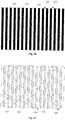
- the content is casted within the predetermined visible range through the display barrier 165 whose electrode is in an off state in the barrier panel 164. That is, when the image frame 10 is displayed through the display device 100, it is disassembled into pieces of display content. Eventually the front view of the image 20 can be illustrated in Fig. 4 .
- the display barrier between two contents is relatively narrow, it can reduce the impact on the final display effects observed by users with eyes as much as possible.
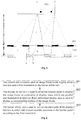
- Each display area 143 has an edge a in the first direction and an edge b in the second direction.
- the predetermined visible range has an edge e in the first direction and an edge f in the second direction.
- edges a, c, and e are on the same plane
- edges b, d, and f are on the same plane, so that content displayed on the each display area 143 can be guaranteed completely visible only within the predetermined visible range. It should be noted that the design for the display area 143 in the most marginal area can be different from the one shown in Fig. 5 .
- the width 510 of the predetermined visible range is set based upon the distance between a user's two user eyes.
- the width 510 between edges e and f is usually a bit wider than the distance between two user eyes. That is, the width 510 of the predetermined visible range is set based upon the distance between two user eyes.
- the predetermined visible range becomes changeable. In this case:
- the first instruction is used to trigger the barrier driver unit 162 to turn on the electrodes of the display barriers at either odd or even number positions on barrier panel 164
- the corresponding positions of the display area 143 on display panel 144 when the electrodes of the display barriers at odd number positions in the barrier panel 164 are turned on are different with those when the electrodes of the display barriers at even number positions in the barrier panel 164 are turned on. Therefore, the third instruction corresponds to the first instruction.
- the control unit 120 can dynamically determine the position for each display area 143 based upon the rules shown in Fig. 5 .
- the presently disclosed embodiment does not limit the methods for the control unit 120 to obtain distance ef between user eyes, the coordinates for user eyes projected on the barrier panel 164, and the distance G between user eyes and barrier panel 164.
- the control unit 120 can obtain those parameters through a front camera or a distance sensor, etc.
- the display device in the embodiment sends a first instruction to the barrier driver unit through the control unit.
- the barrier driver unit then turns on the electrode of the display barrier at either odd or even number position in the barrier panel to block light; meanwhile, the control unit sends the image frame to the display driver unit.
- the display driver unit drives the display panel to display the image frame on the display areas which are the parallel and distributed at intervals. Each display area is used to display the corresponding portion of the image frame.
- Each display area displays its corresponding content which is cast within the predetermined visible range through the display barrier whose electrode is in an on state in the barrier panel. Since a portion of the display barriers in the barrier panel block light, users can only see the image frame within the predetermined visible range through the display barriers whose electrodes are in an off state.
- the image frame When the sight goes beyond the predetermined visible range, the image frame may become blur or incompletely visible due to the blocking of the display barriers. It solves the user's privacy leak issue due to the high visibility and exposure of the content displayed on wide viewing angle display device to other people and achieves the desired effect that the visible range of the display panel can be limited to a certain predetermined visible range and the image frame displayed on the display panel becomes completely or incompletely invisible when the sight goes beyond the predetermined visible range.
- the barrier driver unit turns on the electrodes of all display barriers in the barrier panel according to the second instruction so that the effect of blocking the whole screen can be achieved and user's privacy can be further protected.
- the display driver unit determines the position of each display area according to the third instruction to make the position of display area be corresponding to the position of the display barrier whose the electrode is in an on state in the barrier panel and the content in the display area visible to users within the predetermined visible range.
- control unit can determine the position of each display area according to the distance between two user eyes, the coordinates of user eyes projected on the barrier panel, the distance between user eyes and barrier panel, the distance between barrier panel and display panel to make the predetermined visible range dynamic and determine the position of the display area associated with the position of the user eyes.
- the barrier driver unit be able to send a drive signal through different signal lines to switch screen to narrow viewing angle or blocking state.
- the idle area 145 between two adjacent display areas 143 on display panel 144 may also be used to display preset masked display content.
- Masked display content refers to the display content being visible beyond the predetermined visible range.
- Masked display content can disguise the image frame displayed on the display areas 143.
- the displayed image frame is a game image while the masked one is a website image.
- the game image is only visible in the predetermined visible range while the website image is visible beyond the range.
- Fig. 6 is a flow chart of a display method shown in accordance with an exemplary embodiment. This method is applied to the display device.
- the display device comprises: a control unit, a display driver unit and a barrier driver unit which are connected to the control unit, a display panel which is connected to display driver unit, a barrier panel which is disposed above the display panel and connected to the barrier driver unit, and a plurality of display barriers which are parallel and distributed at intervals in the barrier panel.
- the method comprising:
- the display barrier whose electrode is in an on state blocks light.
- the display barrier whose electrode is in an off state allows light to pass through.
- Each individual display area displays its corresponding content and casts the content to the predetermined visible range through the display barrier whose electrode is in an off state in the barrier panel.
- the display method provided by the presently disclosed embodiment is that the first instruction is sent to the barrier driver unit through the control unit.
- the barrier driver unit then turns on the electrode of the display barrier at either odd or even number position in the barrier panel according to the first instruction to block light; meanwhile, the control unit sends the image frame to the display driver unit.
- the display driver unit drives the display panel to display the image frame on the display areas which are parallel and distributed at intervals. Each display area is used to display the corresponding portion of the image frame.
- Each display area displays its corresponding content which is cast within the predetermined visible range through the display barrier whose electrode is in an on state in the barrier panel.
- the visible range of the display panel can be limited to a certain predetermined visible range and the image frame displayed on the display panel becomes completely invisible or incompletely visible when the sight goes beyond the predetermined visible range.
- the method may include following acts.
- control unit sends the image frame to the display driver unit.
- this step can be executed multiple times periodically or executed when display frames change. For example, the control unit executes this step every 1/24 second.
- display driver unit drives the display panel to display the image frame on the display areas which are parallel and distributed at intervals. Each display area displays its corresponding portion of the image frame.
- control unit is able to determine the position of each display area in accordance with the distance between user eyes, the coordinates of user eyes projected on the barrier panel, the distance between user eyes and barrier panel, and the distance between barrier panel and display panel.
- control unit After the position for each display area is determined, the control unit sends the third instruction to the display driver unit.
- the third instruction is used to determine the position of each display area.
- the step can be replaced with the following steps.
- each display area displays its corresponding content.
- the content can only go through light transmitting area between two adjacent display barriers in the barrier panel and be cast within the predetermined visible range.
- the predetermined visible range is determined by the distance between user eyes.
- the barrier driver unit turns on the electrodes of all display barriers according to the second instruction.
- the barrier driver unit sends a drive signal to the display barriers at odd number positions in the barrier panel through the first signal line.
- the electrodes of the display barriers on the display panel at odd number positions are connected to the first signal line;
- the barrier driver unit sends a drive signal to the display barriers at even number positions in the barrier panel through the second signal line.
- the electrodes of the display barriers in the barrier panel at even number positions are connected to the second signal line.
- the display driver unit turns the idle area between the two adjacent display areas on the display panel to the non-working state or displays the predetermined masked content on the display panel.
- the display method described in the presently disclosed embodiment is that the first instruction is sent to the barrier driver unit through the control unit.
- the barrier driver unit then turns on the electrode of the display barrier at either odd or even number position in the barrier panel according to the first instruction to block light; meanwhile, the control unit sends the image frame to the display driver unit.
- the display driver unit drives the display panel to display the image frame on the display areas which are parallel and distributed at intervals. Each display area is used to display the corresponding portion of the image frame.
- Each display area displays its corresponding content which is cast within the predetermined visible range through the display barrier whose electrode is in an on state in the barrier panel.
- the visible range of the display panel can be limited to a certain predetermined visible range and the image frame displayed on the display panel becomes completely or incompletely invisible when the sight goes beyond the predetermined visible range.
- the barrier driver unit turns on the electrodes of all display barriers according to the second instruction so that the effect of blocking the whole screen can be achieved and user's privacy can be further protected.
- the display driver unit determines the position for each display area according to the third instruction to make the position of the display area be corresponding to the position of the display barrier whose electrode is in an on state in the barrier panel and content in the display area visible to users within the predetermined visible range.
- control unit can determine the position of each display area according to the distance between two user eyes, the coordinates of user eyes projected on the barrier panel, the distance between user eyes and barrier panel, the distance between barrier panel and display panel to make the predetermined visible range dynamic and determine the position of the display area associated with the position of the user eyes.
- the barrier driver unit be able to send the drive signal through different signal lines to switch screen to narrow viewing angle or blocking state.
Landscapes
- Engineering & Computer Science (AREA)
- Theoretical Computer Science (AREA)
- Physics & Mathematics (AREA)
- General Physics & Mathematics (AREA)
- Computer Hardware Design (AREA)
- Multimedia (AREA)
- Software Systems (AREA)
- General Engineering & Computer Science (AREA)
- Computer Security & Cryptography (AREA)
- Health & Medical Sciences (AREA)
- General Health & Medical Sciences (AREA)
- Ophthalmology & Optometry (AREA)
- Human Computer Interaction (AREA)
- Control Of Indicators Other Than Cathode Ray Tubes (AREA)
- Testing, Inspecting, Measuring Of Stereoscopic Televisions And Televisions (AREA)
- Devices For Indicating Variable Information By Combining Individual Elements (AREA)
Applications Claiming Priority (1)
| Application Number | Priority Date | Filing Date | Title |
|---|---|---|---|
| CN201610942895.XA CN106557710B (zh) | 2016-10-31 | 2016-10-31 | 显示设备及显示方法 |
Publications (2)
| Publication Number | Publication Date |
|---|---|
| EP3330954A2 true EP3330954A2 (fr) | 2018-06-06 |
| EP3330954A3 EP3330954A3 (fr) | 2018-09-05 |
Family
ID=58443460
Family Applications (1)
| Application Number | Title | Priority Date | Filing Date |
|---|---|---|---|
| EP17199107.8A Ceased EP3330954A3 (fr) | 2016-10-31 | 2017-10-30 | Afficheur et son procédé d'affichage |
Country Status (3)
| Country | Link |
|---|---|
| US (1) | US10529303B2 (fr) |
| EP (1) | EP3330954A3 (fr) |
| CN (1) | CN106557710B (fr) |
Families Citing this family (4)
| Publication number | Priority date | Publication date | Assignee | Title |
|---|---|---|---|---|
| CN108803863B (zh) | 2017-04-28 | 2020-12-01 | 京东方科技集团股份有限公司 | 一种脑控穿戴显示装置及脑控显示方法 |
| CN107291230B (zh) * | 2017-06-19 | 2019-08-16 | 京东方科技集团股份有限公司 | 脑电波控制方法及装置、显示装置 |
| US11457173B2 (en) | 2020-02-21 | 2022-09-27 | Mediatek Inc. | Dynamic frame rate adjustment mechanism |
| US12124758B2 (en) * | 2023-02-06 | 2024-10-22 | Genesys Logic, Inc. | Multi-host system and operation sharing method |
Citations (1)
| Publication number | Priority date | Publication date | Assignee | Title |
|---|---|---|---|---|
| CN101950550B (zh) * | 2010-09-28 | 2013-05-29 | 冠捷显示科技(厦门)有限公司 | 基于观看者视角显示不同角度画面的显示装置 |
Family Cites Families (14)
| Publication number | Priority date | Publication date | Assignee | Title |
|---|---|---|---|---|
| KR100893618B1 (ko) * | 2008-03-07 | 2009-04-20 | 삼성모바일디스플레이주식회사 | 전자 영상 기기 |
| JP5207175B2 (ja) * | 2008-03-31 | 2013-06-12 | Nltテクノロジー株式会社 | 表示装置、電子機器、光学部材、表示パネル、コントローラ、及び表示パネルの駆動制御方法 |
| US8854531B2 (en) * | 2009-12-31 | 2014-10-07 | Broadcom Corporation | Multiple remote controllers that each simultaneously controls a different visual presentation of a 2D/3D display |
| TW201135688A (en) * | 2010-04-02 | 2011-10-16 | Wistron Corp | Method of providing privacy for a display apparatus and display apparatus |
| CN102222492B (zh) * | 2010-04-13 | 2013-05-22 | 纬创资通股份有限公司 | 显示装置防窥的方法及其装置 |
| US20160225226A1 (en) * | 2010-09-30 | 2016-08-04 | Jesus Pereo-OcHoa | Method and System of Playing Game through Communication Tool |
| KR20130101236A (ko) * | 2012-03-05 | 2013-09-13 | 삼성디스플레이 주식회사 | 배리어 기판, 이를 포함하는 배리어 패널 및 이를 포함하는 입체 영상 표시 장치 |
| CN102625131A (zh) * | 2012-03-20 | 2012-08-01 | 深圳创维-Rgb电子有限公司 | 一种电视机画面的隐私保护系统 |
| TWI467539B (zh) * | 2012-07-20 | 2015-01-01 | Au Optronics Corp | 影像顯示的控制方法以及顯示系統 |
| CN103676301A (zh) * | 2013-12-27 | 2014-03-26 | 京东方科技集团股份有限公司 | 一种显示装置及显示系统 |
| CN104994373A (zh) * | 2015-07-31 | 2015-10-21 | 京东方科技集团股份有限公司 | 三维显示装置及三维显示方法 |
| CN205281069U (zh) * | 2016-01-08 | 2016-06-01 | 京东方科技集团股份有限公司 | 一种显示装置 |
| CN105702171A (zh) | 2016-04-19 | 2016-06-22 | 京东方科技集团股份有限公司 | 显示装置及显示方法 |
| CN106054423A (zh) * | 2016-08-17 | 2016-10-26 | 京东方科技集团股份有限公司 | 一种显示模组及显示装置 |
-
2016
- 2016-10-31 CN CN201610942895.XA patent/CN106557710B/zh active Active
-
2017
- 2017-10-30 EP EP17199107.8A patent/EP3330954A3/fr not_active Ceased
- 2017-10-31 US US15/799,730 patent/US10529303B2/en active Active
Patent Citations (1)
| Publication number | Priority date | Publication date | Assignee | Title |
|---|---|---|---|---|
| CN101950550B (zh) * | 2010-09-28 | 2013-05-29 | 冠捷显示科技(厦门)有限公司 | 基于观看者视角显示不同角度画面的显示装置 |
Also Published As
| Publication number | Publication date |
|---|---|
| CN106557710A (zh) | 2017-04-05 |
| US10529303B2 (en) | 2020-01-07 |
| EP3330954A3 (fr) | 2018-09-05 |
| CN106557710B (zh) | 2022-05-17 |
| US20180122339A1 (en) | 2018-05-03 |
Similar Documents
| Publication | Publication Date | Title |
|---|---|---|
| US10497293B2 (en) | Display device having a barrier panel for displaying wide-viewing and narrow-viewing modes and display method thereof | |
| EP3330954A2 (fr) | Afficheur et son procédé d'affichage | |
| US9632325B2 (en) | Liquid crystal slit grating and stereoscopic display device | |
| TW200506431A (en) | Display unit | |
| US9857601B2 (en) | Display device | |
| US10545266B2 (en) | Display device, lens film and display method | |
| ATE357721T1 (de) | Elektronische vorrichtung mit display | |
| CN104751768A (zh) | 显示器、显示驱动方法和显示系统 | |
| CN104238153A (zh) | 显示装置 | |
| US9628781B2 (en) | Display device | |
| JP2015502560A (ja) | 画素構造及びその制御方法、並びにディスプレイパネル | |
| US20160062720A1 (en) | Display device | |
| CN107229146B (zh) | 显示设备及显示方法 | |
| CN107229142B (zh) | 显示设备及显示方法 | |
| CN108267860B (zh) | 头戴式显示装置 | |
| JP2014228852A (ja) | 表示装置 | |
| JP2014178366A (ja) | 表示装置 | |
| CN107229130B (zh) | 显示设备及显示方法 | |
| CN107229147B (zh) | 液晶显示设备及显示方法 | |
| CN106526914B (zh) | 显示设备及显示方法 | |
| KR20160082615A (ko) | 사용자 위치 중심의 보안 필름 | |
| CN107230424B (zh) | 显示设备及显示方法 | |
| CN104181696A (zh) | 显示装置 | |
| GB2511141A (en) | Stereoscopic parallax barrier display apparatus and display method |
Legal Events
| Date | Code | Title | Description |
|---|---|---|---|
| PUAI | Public reference made under article 153(3) epc to a published international application that has entered the european phase |
Free format text: ORIGINAL CODE: 0009012 |
|
| STAA | Information on the status of an ep patent application or granted ep patent |
Free format text: STATUS: THE APPLICATION HAS BEEN PUBLISHED |
|
| AK | Designated contracting states |
Kind code of ref document: A2 Designated state(s): AL AT BE BG CH CY CZ DE DK EE ES FI FR GB GR HR HU IE IS IT LI LT LU LV MC MK MT NL NO PL PT RO RS SE SI SK SM TR |
|
| AX | Request for extension of the european patent |
Extension state: BA ME |
|
| PUAL | Search report despatched |
Free format text: ORIGINAL CODE: 0009013 |
|
| AK | Designated contracting states |
Kind code of ref document: A3 Designated state(s): AL AT BE BG CH CY CZ DE DK EE ES FI FR GB GR HR HU IE IS IT LI LT LU LV MC MK MT NL NO PL PT RO RS SE SI SK SM TR |
|
| AX | Request for extension of the european patent |
Extension state: BA ME |
|
| RIC1 | Information provided on ipc code assigned before grant |
Ipc: G09G 3/20 20060101AFI20180802BHEP |
|
| STAA | Information on the status of an ep patent application or granted ep patent |
Free format text: STATUS: REQUEST FOR EXAMINATION WAS MADE |
|
| 17P | Request for examination filed |
Effective date: 20190305 |
|
| RBV | Designated contracting states (corrected) |
Designated state(s): AL AT BE BG CH CY CZ DE DK EE ES FI FR GB GR HR HU IE IS IT LI LT LU LV MC MK MT NL NO PL PT RO RS SE SI SK SM TR |
|
| STAA | Information on the status of an ep patent application or granted ep patent |
Free format text: STATUS: EXAMINATION IS IN PROGRESS |
|
| 17Q | First examination report despatched |
Effective date: 20200422 |
|
| STAA | Information on the status of an ep patent application or granted ep patent |
Free format text: STATUS: THE APPLICATION HAS BEEN REFUSED |
|
| 18R | Application refused |
Effective date: 20220131 |