EP3332902A1 - Systeme und verfahren zur herstellung einer metallverstärkung der laufradschaufel eines turbotriebwerks - Google Patents
Systeme und verfahren zur herstellung einer metallverstärkung der laufradschaufel eines turbotriebwerks Download PDFInfo
- Publication number
- EP3332902A1 EP3332902A1 EP17206441.2A EP17206441A EP3332902A1 EP 3332902 A1 EP3332902 A1 EP 3332902A1 EP 17206441 A EP17206441 A EP 17206441A EP 3332902 A1 EP3332902 A1 EP 3332902A1
- Authority
- EP
- European Patent Office
- Prior art keywords
- central portion
- flank
- sheath
- sleeve
- lower sleeve
- Prior art date
- Legal status (The legal status is an assumption and is not a legal conclusion. Google has not performed a legal analysis and makes no representation as to the accuracy of the status listed.)
- Granted
Links
Images

Classifications
-
- B—PERFORMING OPERATIONS; TRANSPORTING
- B23—MACHINE TOOLS; METAL-WORKING NOT OTHERWISE PROVIDED FOR
- B23K—SOLDERING OR UNSOLDERING; WELDING; CLADDING OR PLATING BY SOLDERING OR WELDING; CUTTING BY APPLYING HEAT LOCALLY, e.g. FLAME CUTTING; WORKING BY LASER BEAM
- B23K9/00—Arc welding or cutting
- B23K9/04—Welding for other purposes than joining, e.g. built-up welding
- B23K9/044—Built-up welding on three-dimensional surfaces
-
- B—PERFORMING OPERATIONS; TRANSPORTING
- B22—CASTING; POWDER METALLURGY
- B22F—WORKING METALLIC POWDER; MANUFACTURE OF ARTICLES FROM METALLIC POWDER; MAKING METALLIC POWDER; APPARATUS OR DEVICES SPECIALLY ADAPTED FOR METALLIC POWDER
- B22F10/00—Additive manufacturing of workpieces or articles from metallic powder
- B22F10/20—Direct sintering or melting
- B22F10/25—Direct deposition of metal particles, e.g. direct metal deposition [DMD] or laser engineered net shaping [LENS]
-
- B—PERFORMING OPERATIONS; TRANSPORTING
- B22—CASTING; POWDER METALLURGY
- B22F—WORKING METALLIC POWDER; MANUFACTURE OF ARTICLES FROM METALLIC POWDER; MAKING METALLIC POWDER; APPARATUS OR DEVICES SPECIALLY ADAPTED FOR METALLIC POWDER
- B22F5/00—Manufacture of workpieces or articles from metallic powder characterised by the special shape of the product
- B22F5/04—Manufacture of workpieces or articles from metallic powder characterised by the special shape of the product of turbine blades
-
- B—PERFORMING OPERATIONS; TRANSPORTING
- B22—CASTING; POWDER METALLURGY
- B22F—WORKING METALLIC POWDER; MANUFACTURE OF ARTICLES FROM METALLIC POWDER; MAKING METALLIC POWDER; APPARATUS OR DEVICES SPECIALLY ADAPTED FOR METALLIC POWDER
- B22F7/00—Manufacture of composite layers, workpieces, or articles, comprising metallic powder, by sintering the powder, with or without compacting wherein at least one part is obtained by sintering or compression
- B22F7/06—Manufacture of composite layers, workpieces, or articles, comprising metallic powder, by sintering the powder, with or without compacting wherein at least one part is obtained by sintering or compression of composite workpieces or articles from parts, e.g. to form tipped tools
- B22F7/062—Manufacture of composite layers, workpieces, or articles, comprising metallic powder, by sintering the powder, with or without compacting wherein at least one part is obtained by sintering or compression of composite workpieces or articles from parts, e.g. to form tipped tools involving the connection or repairing of preformed parts
-
- B—PERFORMING OPERATIONS; TRANSPORTING
- B23—MACHINE TOOLS; METAL-WORKING NOT OTHERWISE PROVIDED FOR
- B23K—SOLDERING OR UNSOLDERING; WELDING; CLADDING OR PLATING BY SOLDERING OR WELDING; CUTTING BY APPLYING HEAT LOCALLY, e.g. FLAME CUTTING; WORKING BY LASER BEAM
- B23K15/00—Electron-beam welding or cutting
- B23K15/0046—Welding
- B23K15/0086—Welding welding for purposes other than joining, e.g. build-up welding
-
- B—PERFORMING OPERATIONS; TRANSPORTING
- B23—MACHINE TOOLS; METAL-WORKING NOT OTHERWISE PROVIDED FOR
- B23K—SOLDERING OR UNSOLDERING; WELDING; CLADDING OR PLATING BY SOLDERING OR WELDING; CUTTING BY APPLYING HEAT LOCALLY, e.g. FLAME CUTTING; WORKING BY LASER BEAM
- B23K26/00—Working by laser beam, e.g. welding, cutting or boring
- B23K26/34—Laser welding for purposes other than joining
- B23K26/342—Build-up welding
-
- B—PERFORMING OPERATIONS; TRANSPORTING
- B23—MACHINE TOOLS; METAL-WORKING NOT OTHERWISE PROVIDED FOR
- B23P—METAL-WORKING NOT OTHERWISE PROVIDED FOR; COMBINED OPERATIONS; UNIVERSAL MACHINE TOOLS
- B23P15/00—Making specific metal objects by operations not covered by a single other subclass or a group in this subclass
- B23P15/04—Making specific metal objects by operations not covered by a single other subclass or a group in this subclass turbine or like blades from several pieces
-
- B—PERFORMING OPERATIONS; TRANSPORTING
- B33—ADDITIVE MANUFACTURING TECHNOLOGY
- B33Y—ADDITIVE MANUFACTURING, i.e. MANUFACTURING OF THREE-DIMENSIONAL [3D] OBJECTS BY ADDITIVE DEPOSITION, ADDITIVE AGGLOMERATION OR ADDITIVE LAYERING, e.g. BY 3D PRINTING, STEREOLITHOGRAPHY OR SELECTIVE LASER SINTERING
- B33Y80/00—Products made by additive manufacturing
-
- F—MECHANICAL ENGINEERING; LIGHTING; HEATING; WEAPONS; BLASTING
- F01—MACHINES OR ENGINES IN GENERAL; ENGINE PLANTS IN GENERAL; STEAM ENGINES
- F01D—NON-POSITIVE DISPLACEMENT MACHINES OR ENGINES, e.g. STEAM TURBINES
- F01D5/00—Blades; Blade-carrying members; Heating, heat-insulating, cooling or antivibration means on the blades or the members
- F01D5/12—Blades
- F01D5/14—Form or construction
- F01D5/147—Construction, i.e. structural features, e.g. of weight-saving hollow blades
-
- F—MECHANICAL ENGINEERING; LIGHTING; HEATING; WEAPONS; BLASTING
- F01—MACHINES OR ENGINES IN GENERAL; ENGINE PLANTS IN GENERAL; STEAM ENGINES
- F01D—NON-POSITIVE DISPLACEMENT MACHINES OR ENGINES, e.g. STEAM TURBINES
- F01D5/00—Blades; Blade-carrying members; Heating, heat-insulating, cooling or antivibration means on the blades or the members
- F01D5/12—Blades
- F01D5/28—Selecting particular materials; Particular measures relating thereto; Measures against erosion or corrosion
- F01D5/286—Particular treatment of blades, e.g. to increase durability or resistance against corrosion or erosion
-
- F—MECHANICAL ENGINEERING; LIGHTING; HEATING; WEAPONS; BLASTING
- F04—POSITIVE - DISPLACEMENT MACHINES FOR LIQUIDS; PUMPS FOR LIQUIDS OR ELASTIC FLUIDS
- F04D—NON-POSITIVE-DISPLACEMENT PUMPS
- F04D29/00—Details, component parts, or accessories
- F04D29/02—Selection of particular materials
- F04D29/023—Selection of particular materials especially adapted for elastic fluid pumps
-
- F—MECHANICAL ENGINEERING; LIGHTING; HEATING; WEAPONS; BLASTING
- F04—POSITIVE - DISPLACEMENT MACHINES FOR LIQUIDS; PUMPS FOR LIQUIDS OR ELASTIC FLUIDS
- F04D—NON-POSITIVE-DISPLACEMENT PUMPS
- F04D29/00—Details, component parts, or accessories
- F04D29/26—Rotors specially for elastic fluids
- F04D29/32—Rotors specially for elastic fluids for axial flow pumps
- F04D29/321—Rotors specially for elastic fluids for axial flow pumps for axial flow compressors
- F04D29/324—Blades
-
- F—MECHANICAL ENGINEERING; LIGHTING; HEATING; WEAPONS; BLASTING
- F04—POSITIVE - DISPLACEMENT MACHINES FOR LIQUIDS; PUMPS FOR LIQUIDS OR ELASTIC FLUIDS
- F04D—NON-POSITIVE-DISPLACEMENT PUMPS
- F04D29/00—Details, component parts, or accessories
- F04D29/26—Rotors specially for elastic fluids
- F04D29/32—Rotors specially for elastic fluids for axial flow pumps
- F04D29/325—Rotors specially for elastic fluids for axial flow pumps for axial flow fans
-
- F—MECHANICAL ENGINEERING; LIGHTING; HEATING; WEAPONS; BLASTING
- F04—POSITIVE - DISPLACEMENT MACHINES FOR LIQUIDS; PUMPS FOR LIQUIDS OR ELASTIC FLUIDS
- F04D—NON-POSITIVE-DISPLACEMENT PUMPS
- F04D29/00—Details, component parts, or accessories
- F04D29/26—Rotors specially for elastic fluids
- F04D29/32—Rotors specially for elastic fluids for axial flow pumps
- F04D29/38—Blades
- F04D29/388—Blades characterised by construction
-
- B—PERFORMING OPERATIONS; TRANSPORTING
- B22—CASTING; POWDER METALLURGY
- B22F—WORKING METALLIC POWDER; MANUFACTURE OF ARTICLES FROM METALLIC POWDER; MAKING METALLIC POWDER; APPARATUS OR DEVICES SPECIALLY ADAPTED FOR METALLIC POWDER
- B22F10/00—Additive manufacturing of workpieces or articles from metallic powder
- B22F10/50—Treatment of workpieces or articles during build-up, e.g. treatments applied to fused layers during build-up
-
- B—PERFORMING OPERATIONS; TRANSPORTING
- B22—CASTING; POWDER METALLURGY
- B22F—WORKING METALLIC POWDER; MANUFACTURE OF ARTICLES FROM METALLIC POWDER; MAKING METALLIC POWDER; APPARATUS OR DEVICES SPECIALLY ADAPTED FOR METALLIC POWDER
- B22F10/00—Additive manufacturing of workpieces or articles from metallic powder
- B22F10/60—Treatment of workpieces or articles after build-up
- B22F10/66—Treatment of workpieces or articles after build-up by mechanical means
-
- B—PERFORMING OPERATIONS; TRANSPORTING
- B23—MACHINE TOOLS; METAL-WORKING NOT OTHERWISE PROVIDED FOR
- B23K—SOLDERING OR UNSOLDERING; WELDING; CLADDING OR PLATING BY SOLDERING OR WELDING; CUTTING BY APPLYING HEAT LOCALLY, e.g. FLAME CUTTING; WORKING BY LASER BEAM
- B23K2101/00—Articles made by soldering, welding or cutting
- B23K2101/001—Turbines
-
- B—PERFORMING OPERATIONS; TRANSPORTING
- B23—MACHINE TOOLS; METAL-WORKING NOT OTHERWISE PROVIDED FOR
- B23K—SOLDERING OR UNSOLDERING; WELDING; CLADDING OR PLATING BY SOLDERING OR WELDING; CUTTING BY APPLYING HEAT LOCALLY, e.g. FLAME CUTTING; WORKING BY LASER BEAM
- B23K2103/00—Materials to be soldered, welded or cut
- B23K2103/08—Non-ferrous metals or alloys
- B23K2103/14—Titanium or alloys thereof
-
- F—MECHANICAL ENGINEERING; LIGHTING; HEATING; WEAPONS; BLASTING
- F02—COMBUSTION ENGINES; HOT-GAS OR COMBUSTION-PRODUCT ENGINE PLANTS
- F02K—JET-PROPULSION PLANTS
- F02K3/00—Plants including a gas turbine driving a compressor or a ducted fan
- F02K3/02—Plants including a gas turbine driving a compressor or a ducted fan in which part of the working fluid by-passes the turbine and combustion chamber
- F02K3/04—Plants including a gas turbine driving a compressor or a ducted fan in which part of the working fluid by-passes the turbine and combustion chamber the plant including ducted fans, i.e. fans with high volume, low pressure outputs, for augmenting the jet thrust, e.g. of double-flow type
- F02K3/06—Plants including a gas turbine driving a compressor or a ducted fan in which part of the working fluid by-passes the turbine and combustion chamber the plant including ducted fans, i.e. fans with high volume, low pressure outputs, for augmenting the jet thrust, e.g. of double-flow type with front fan
-
- F—MECHANICAL ENGINEERING; LIGHTING; HEATING; WEAPONS; BLASTING
- F05—INDEXING SCHEMES RELATING TO ENGINES OR PUMPS IN VARIOUS SUBCLASSES OF CLASSES F01-F04
- F05D—INDEXING SCHEME FOR ASPECTS RELATING TO NON-POSITIVE-DISPLACEMENT MACHINES OR ENGINES, GAS-TURBINES OR JET-PROPULSION PLANTS
- F05D2220/00—Application
- F05D2220/30—Application in turbines
- F05D2220/36—Application in turbines specially adapted for the fan of turbofan engines
-
- F—MECHANICAL ENGINEERING; LIGHTING; HEATING; WEAPONS; BLASTING
- F05—INDEXING SCHEMES RELATING TO ENGINES OR PUMPS IN VARIOUS SUBCLASSES OF CLASSES F01-F04
- F05D—INDEXING SCHEME FOR ASPECTS RELATING TO NON-POSITIVE-DISPLACEMENT MACHINES OR ENGINES, GAS-TURBINES OR JET-PROPULSION PLANTS
- F05D2230/00—Manufacture
- F05D2230/30—Manufacture with deposition of material
- F05D2230/31—Layer deposition
-
- F—MECHANICAL ENGINEERING; LIGHTING; HEATING; WEAPONS; BLASTING
- F05—INDEXING SCHEMES RELATING TO ENGINES OR PUMPS IN VARIOUS SUBCLASSES OF CLASSES F01-F04
- F05D—INDEXING SCHEME FOR ASPECTS RELATING TO NON-POSITIVE-DISPLACEMENT MACHINES OR ENGINES, GAS-TURBINES OR JET-PROPULSION PLANTS
- F05D2240/00—Components
- F05D2240/20—Rotors
- F05D2240/30—Characteristics of rotor blades, i.e. of any element transforming dynamic fluid energy to or from rotational energy and being attached to a rotor
- F05D2240/303—Characteristics of rotor blades, i.e. of any element transforming dynamic fluid energy to or from rotational energy and being attached to a rotor related to the leading edge of a rotor blade
-
- F—MECHANICAL ENGINEERING; LIGHTING; HEATING; WEAPONS; BLASTING
- F05—INDEXING SCHEMES RELATING TO ENGINES OR PUMPS IN VARIOUS SUBCLASSES OF CLASSES F01-F04
- F05D—INDEXING SCHEME FOR ASPECTS RELATING TO NON-POSITIVE-DISPLACEMENT MACHINES OR ENGINES, GAS-TURBINES OR JET-PROPULSION PLANTS
- F05D2300/00—Materials; Properties thereof
- F05D2300/10—Metals, alloys or intermetallic compounds
- F05D2300/12—Light metals
- F05D2300/121—Aluminium
-
- F—MECHANICAL ENGINEERING; LIGHTING; HEATING; WEAPONS; BLASTING
- F05—INDEXING SCHEMES RELATING TO ENGINES OR PUMPS IN VARIOUS SUBCLASSES OF CLASSES F01-F04
- F05D—INDEXING SCHEME FOR ASPECTS RELATING TO NON-POSITIVE-DISPLACEMENT MACHINES OR ENGINES, GAS-TURBINES OR JET-PROPULSION PLANTS
- F05D2300/00—Materials; Properties thereof
- F05D2300/10—Metals, alloys or intermetallic compounds
- F05D2300/13—Refractory metals, i.e. Ti, V, Cr, Zr, Nb, Mo, Hf, Ta, W
- F05D2300/133—Titanium
-
- F—MECHANICAL ENGINEERING; LIGHTING; HEATING; WEAPONS; BLASTING
- F05—INDEXING SCHEMES RELATING TO ENGINES OR PUMPS IN VARIOUS SUBCLASSES OF CLASSES F01-F04
- F05D—INDEXING SCHEME FOR ASPECTS RELATING TO NON-POSITIVE-DISPLACEMENT MACHINES OR ENGINES, GAS-TURBINES OR JET-PROPULSION PLANTS
- F05D2300/00—Materials; Properties thereof
- F05D2300/10—Metals, alloys or intermetallic compounds
- F05D2300/17—Alloys
- F05D2300/171—Steel alloys
-
- Y—GENERAL TAGGING OF NEW TECHNOLOGICAL DEVELOPMENTS; GENERAL TAGGING OF CROSS-SECTIONAL TECHNOLOGIES SPANNING OVER SEVERAL SECTIONS OF THE IPC; TECHNICAL SUBJECTS COVERED BY FORMER USPC CROSS-REFERENCE ART COLLECTIONS [XRACs] AND DIGESTS
- Y02—TECHNOLOGIES OR APPLICATIONS FOR MITIGATION OR ADAPTATION AGAINST CLIMATE CHANGE
- Y02P—CLIMATE CHANGE MITIGATION TECHNOLOGIES IN THE PRODUCTION OR PROCESSING OF GOODS
- Y02P10/00—Technologies related to metal processing
- Y02P10/25—Process efficiency
Definitions
- the disclosure relates generally to sheaths for airfoils in gas turbine engines.
- Fans are complex rotating systems that may encounter undesirable conditions during normal operation. Fans may be subject to debris entering an engine inlet. The debris may contact the blades of the fan at the leading edge, causing damage. Blade sheaths may protect the leading edge of fan blades. The blade sheaths are often made using costly techniques and/or techniques that may leave microstructural anomalies.
- Blade sheaths are typically produced using subtractive methods such as milling and machining techniques. These techniques typically have a high cost, low productivity rates, and long lead times. Many other subtractive methods considered for blade sheaths are limited in dimensional accuracy, surface finish, material integrity, and throughput.
- a method of making a sheath for an airfoil includes the steps of forming an upper sleeve and a lower sleeve, and forming a central portion bonded to the upper sleeve and the lower sleeve.
- the central portion may be formed by depositing a material on the upper sleeve and the lower sleeve. A portion of the material may be removed from at least one of the central portion, the upper sleeve, or the lower sleeve.
- the material may be deposited using wire arc additive manufacturing.
- the upper sleeve may be fixed relative to the lower sleeve prior to forming the central portion.
- the upper sleeve and the lower sleeve may also be formed from a sheet metal.
- the central portion may be formed by applying a heat source to a wire comprising titanium.
- the lower sleeve and the upper sleeve may be made of titanium, aluminum, nickel, steel, and/or their alloys.
- the sheath may be bonded to the airfoil with an adhesive.
- An internal surface of the central portion may be formed having a curved geometry, and the internal surface may joins the upper sleeve and the lower sleeve.
- a protective coating may be formed on the internal surface.
- a sheath for an airfoil is also provided.
- the sheath may include a first flank, a central portion bonded to the first flank, and a second flank bonded to the central portion.
- the central portion may be deposited using additive manufacturing.
- the central portion has a substantially uniform microstructure as a result of additive manufacturing.
- the first flank and/or second flank may be formed from a sheet of a metal including titanium, aluminum, nickel, and/or steel.
- the central portion may be formed from a titanium alloy.
- An inner surface may be formed with a curved surface to join the first flank and the second flank.
- the inner surface may be substantially smooth with a substantially uniform microstructure.
- a fan for a gas turbine engine may include a blade having a leading edge, a pressure side, a suction side, and a trailing edge.
- a sheath may be bonded to the blade by an adhesive.
- the sheath may have a first flank on the pressure side, a second flank on the suction side, and a central portion joining the first flank and the second flank.
- the central portion may have a substantially uniform microstructure.
- the central portion may be formed by applying a heat source to a wire to deposit material on the first flank and the second flank.
- the sheath may comprise at least one of titanium, aluminum, nickel, or steel.
- An inner surface of the central portion that joins the first flank and the second flank may be substantially smooth.
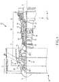
- Gas turbine engine 20 may be a two-spool turbofan that generally incorporates a fan section 22, a compressor section 24, a combustor section 26 and a turbine section 28.
- Alternative engines may include, for example, an augmentor section among other systems or features.
- fan section 22 can drive fluid (e.g., air) along a bypass-flow path B while compressor section 24 can drive coolant along a core-flow path C for compression and communication into combustor section 26 then expansion through turbine section 28.
- fluid e.g., air
- compressor section 24 can drive coolant along a core-flow path C for compression and communication into combustor section 26 then expansion through turbine section 28.
- turbofan gas turbine engine 20 Although depicted as a two-spool turbofan gas turbine engine 20 herein, it should be understood that the concepts described herein are not limited to use with two-spool turbofans as the teachings may be applied to other types of turbine engines including turbojet, turboprop, turboshaft, or power generation turbines, with or without geared fan, geared compressor or three-spool architectures.
- Gas turbine engine 20 may generally comprise a low speed spool 30 and a high speed spool 32 mounted for rotation about an engine central longitudinal axis A-A' relative to an engine static structure 36 via several bearing systems 38, 38-1, and 38-2. It should be understood that various bearing systems 38 at various locations may alternatively or additionally be provided, including for example, bearing system 38, bearing system 38-1, and bearing system 38-2.
- Low speed spool 30 may generally comprise an inner shaft 40 that interconnects a fan 42, a low-pressure compressor 44 and a low-pressure turbine 46.
- Inner shaft 40 may be connected to fan 42 through a geared architecture 48 that can drive fan 42 at a lower speed than low speed spool 30.
- Fan 42 (or other rotating sections having airfoils such as compressor section 24 or turbine section 28) may include a protective sheath along the leading edge of the airfoils.
- Geared architecture 48 may comprise a gear assembly enclosed within a gear housing that couples inner shaft 40 to a rotating fan structure.
- High speed spool 32 may comprise an outer shaft 50 that interconnects a high-pressure compressor 52 and high-pressure turbine 54.
- Airfoils 55 coupled to a rotor of high-pressure turbine may rotate about the engine central longitudinal axis A-A' or airfoils 55 coupled to a stator may be rotationally fixed about engine central longitudinal axis A-A'.
- a combustor 56 may be located between high-pressure compressor 52 and high-pressure turbine 54.
- Inner shaft 40 and outer shaft 50 may be concentric and rotate via bearing systems 38 about the engine central longitudinal axis A-A', which is collinear with their longitudinal axes.
- a "high-pressure” compressor or turbine experiences a higher pressure than a corresponding "low-pressure” compressor or turbine.
- the core airflow along core-flow path C may be compressed by low-pressure compressor 44 then high-pressure compressor 52, mixed and burned with fuel in combustor 56, then expanded over high-pressure turbine 54 and low-pressure turbine 46.
- Turbines 46, 54 rotationally drive the respective low speed spool 30 and high speed spool 32 in response to the expansion.
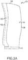
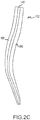
- Blade 130 with sheath 132 is shown according to various embodiments.
- Blade 130 may be a blade of fan 42 of FIG. 1 , for example, and may also be referred to as an airfoil.
- Sheath 132 includes solid portion 148 covering leading edge 136 with and tapered flanks 150 extending from each side of solid portion 148 to cover at least a portion of suction side 144 and pressure side 146.
- sheath 132 covers leading edge 136 of blade 130 with solid portion 148 by adhesively bonding the tapered flanks 150 to suction side 144 and pressure side 146 of blade 130 with a scrim sheet between sheath 132 and blade 130.
- Tapered flanks 150 can be bonded to suction side 144 and pressure side 146 with various adhesives including, but not limited to, rubber, synthetic rubber, silicone or epoxy resin.
- a scrim sheet can be a thin textile which provides a separation between the different materials of sheath 132 and blade 130, protecting blade 130 from its susceptibility to galvanic corrosion where sheath 132 is bonded to blade 130.
- Sheath 132 can be made of titanium, aluminum, nickel, or steel (including alloys of any) or other materials with sufficient stiffness, strength and erosion resistance to withstand the impact loads, static and fatigue loads, or particulate and rain erosion that may be experienced on the leading edge of an airfoil.
- the length of solid portion 148 (extending out from leading edge 136 and from tip 140) can vary widely, but may be sufficiently long to provide protection for leading edge 136 of blade 130.
- the length of tapered flanks 150 can be varied on each side of blade 130 depending on various design considerations of blade 130 and sheath 132. In the example shown, tapered flank 150 on pressure side extends further in the chord-wise direction to provide extra large scale impact protection such as a bird strike, for example, in portions of blade 130 where blade 130 is vulnerable to impacts.
- Sheath 132 provides extra strength and stiffness to blade 130, allowing blade 130 to be made of lightweight materials.
- Solid portion 148 of sheath 132 provides a layer of protection from impact loads as well as erosion for leading edge 136 of airfoil.
- Tapered flanks 150 bond the solid portion 148 to airfoil to hold the solid portion 148 in place.
- leading edge 136 of solid portion 148 can be coated with a thin layer of erosion resistant coating to provide increased erosion resistance.
- This coating may be a cermet, for example, WC or Cr 2 C 2 containing material, or a harder metallic material such as nick or cobalt based hard alloys. Other coating materials may also be suitable for surfaces of sheath 132.
- Tapered flanks 150 may further provide stiffness to blade 130 as well as surface area for a smooth load transfer during impacts to blade 130.
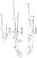
- FIGs. 3A, 3B, and 3C illustrate the process of making a sheath 170 using additive manufacturing, in accordance with various embodiments.
- upper sleeve 172 and lower sleeve 174 are formed separately.
- upper sleeve and lower sleeve are used with reference to the cross-sectional view of FIG. 3A to distinguish the two sleeves, no specific orientation is meant to be implied by the labels upper and lower.
- Upper sleeve 172 and lower sleeve 174 may be formed in a shape similar to tapered flanks 150 described above.
- Upper sleeve 172 and lower sleeve 174 may be formed from a metallic material.
- Upper sleeve and lower sleeve may be formed from titanium, aluminum, nickel, steel, alloys thereof, or other metallic materials.
- Upper sleeve 172 and lower sleeve 174 may be formed of the same material, or of different materials in various embodiments.
- upper sleeve 172 and lower sleeve 174 may be formed from sheet metal comprising titanium alloy.
- Upper sleeve 172 and lower sleeve 174 may be long sheets of material that have a contour matching a blade 130 (of FIG. 2A ) along the pressure side or suction side.
- Upper sleeve 172 and lower sleeve 174 may be formed using various techniques including hot forming, rolling, machining, sheet metal, extrusion, and/or additive manufacturing. Upper sleeve 172 and lower sleeve 174 may be formed as completely disconnected sleeves and later connected. Upper sleeve 172 and lower sleeve 174 may also be formed as partially connected or connected sleeves suitable for deposition of a central leading edge.
- additive manufacturing technology is used to join the upper sleeve 172 and lower sleeve 174 by building a central portion 176.
- Upper sleeve 172 and lower sleeve 174 may be clamped to a mandrel or other mechanical device, for example, to hold or fix the sleeves in position relative to one another.
- wire arc additive manufacturing may be used to build central portion 176.
- an electric arc such as a tungsten inert gas (TIG) or metal inert gas (MIG) source, for example, may be used as heat source 182.
- TOG tungsten inert gas
- MIG metal inert gas
- a wire 184 as may be used as feedstock.
- WAAM may further include using welding power sources, torches, and/or wire feeding systems to deposit material from wire 184 onto a workpiece such as central portion 176, for example.
- Upper sleeve 172 and/or lower sleeve 174 may be micro-roughened prior to deposition of central portion 176 to improve bonding characteristics.
- the WAAM process may use arc control systems to robotically deposit material.
- wire 184 may be fed in the direction of the central portion 176 and make contact.
- the control system may detect wire 184 in contact with central portion 176 and retract the wire until it wire 184 at a desired ignition distance from the central portion 176.
- Motion may be provided by robotic systems to position wire 184 at the desired location relative to central portion 176 and apply the heat source to the wire.
- Central portion 176 may include a bond line 178 where central portion 176 is deposited on and bonded to upper sleeve 172 and lower sleeve 174.
- Central portion 176 may also include rough surfaces 180 in an unfinished form.
- sheath 170 may be shaped into its final dimensions using machining to remove material, though other techniques may also be used.
- a thickness T 1 of upper sleeve 172 at a distal end may be approximately 0.040 inches (1.02 mm). The term approximately as used with dimensions is meant to mean a variety of possible ranges including +/-5%, +/-10%, +/-15%, or +/-20, for example.
- Lower sleeve 174 may be generally thinner than upper sleeve 172.
- Lower sleeve 174 may have a thickness T 2 at a distal end of approximately 0.020 inches (0.51 mm).
- the thickness of lower sleeve 174 and upper sleeve 172 may increase with proximity to central portion 176.
- Lower sleeve 174 and upper sleeve 172 may form the tapered flanks 150 (of FIG. 2A ).
- Central portion 176 may have a thickness T 3 of approximately 1-2 inches.
- Internal surface 188 of joining the upper sleeve 172 and lower sleeve 174 may be a curved surface. The curve may be radial or multi-radial, hyperbolic, or any other suitable curve.
- internal surface 188 may have a radius of curvature of approximately 0.040 inches (1.02 mm).
- Outer surface 190 and internal surface 188 may be finished into smooth surfaces and treated with optional protective coatings to reduce corrosion and/or improve ware characteristics.
- Inner portion 192 of central portion 176 may be formed deposited material with a uniform microstructure.
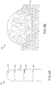
- FIGs. 4A and 4B a microstructure of a sheath 132 (of FIG 2A ) formed using additive manufacturing is shown, in accordance with various embodiments. Sheaths formed using the additive manufacturing as described herein may also improve quality by eliminating microstructure flaws generated by traditional techniques, such as forming internal folds and crack at internal surface 188 (of FIG. 3C ).
- Microstructure 200 of FIG. 4A illustrates various layers 202 with bond lines 204 where each layer of material was deposited using additive manufacturing.
- Microstructure 200 illustrates a multi-layer titanium alloy wall built using WAAM.
- FIG. 4B illustrates a substantially uniform microstructure 210 of a titanium deposit 212.
- the microstructures of FIGs. 4A and 4B are substantially uniform and may have improved strength characteristics compared to less uniform microstructures.
- a substantially uniform microstructure may also lack folds and cracks associated with various manufacturing technologies.
- Components made using WAAM may include a grain structure grown in the direction of material being added.
- the surfaces of a sheath made with additive manufacturing may thus be smooth.
- the sheaths may have internal structural details that cannot be machined into the components due to lack of access such as, for example, internal surface 188 of FIG. 3C .
- Surfaces made using WAAM, EBAM, or similar weld-like techniques may deposit material in a series of cylindrical layers formed one on top of another.
- a wall formed by the techniques may thus have varying width corresponding to the cylindrical profile of each layer.
- the strength of the wall may be limited by the thin portions of the wall.
- the excess material may be removed from each layer during the deposition process or after the deposition process.
- forming a sheath of the present disclosure using WAAM and/or EBAM manufacturing may also include depositing a layer of material, removing excess material from the layer to give the layer a substantially smooth surface, depositing another layer of the layer of uniform width, and removing the excess material from the second layer to give the second layer a substantially smooth surface. This process may be continued throughout the build of the entire sheath. In various embodiments of the build process, several layers of material could be deposited, followed by a clean-up process which would remove excess material from the entire wall surface, creating a wall with a substantially smooth surface.
- sheaths of the present disclosure formed using additive manufacturing may be formed with greater productivity rates.
- the WAAM build rate may be 3 time higher than laser powder deposition.
- the additive manufacturing techniques described herein may reduce the cost associated with sheath production by eliminating costly hot forming operations and greatly reducing machining of external surfaces.
- references to “one embodiment”, “an embodiment”, “an example embodiment”, etc. indicate that the embodiment described may include a particular feature, structure, or characteristic, but every embodiment may not necessarily include the particular feature, structure, or characteristic. Moreover, such phrases are not necessarily referring to the same embodiment. Further, when a particular feature, structure, or characteristic is described in connection with an embodiment, it is submitted that it is within the knowledge of one skilled in the art to affect such feature, structure, or characteristic in connection with other embodiments whether or not explicitly described. After reading the description, it will be apparent to one skilled in the relevant art(s) how to implement the disclosure in alternative embodiment
Landscapes
- Engineering & Computer Science (AREA)
- Mechanical Engineering (AREA)
- General Engineering & Computer Science (AREA)
- Manufacturing & Machinery (AREA)
- Materials Engineering (AREA)
- Chemical & Material Sciences (AREA)
- Physics & Mathematics (AREA)
- Optics & Photonics (AREA)
- Plasma & Fusion (AREA)
- Architecture (AREA)
- Composite Materials (AREA)
- Structures Of Non-Positive Displacement Pumps (AREA)
- Turbine Rotor Nozzle Sealing (AREA)
Applications Claiming Priority (1)
| Application Number | Priority Date | Filing Date | Title |
|---|---|---|---|
| US15/374,676 US10626883B2 (en) | 2016-12-09 | 2016-12-09 | Systems and methods for making blade sheaths |
Publications (2)
| Publication Number | Publication Date |
|---|---|
| EP3332902A1 true EP3332902A1 (de) | 2018-06-13 |
| EP3332902B1 EP3332902B1 (de) | 2025-10-08 |
Family
ID=60661822
Family Applications (1)
| Application Number | Title | Priority Date | Filing Date |
|---|---|---|---|
| EP17206441.2A Active EP3332902B1 (de) | 2016-12-09 | 2017-12-11 | Systeme und verfahren zur herstellung einer metallverstärkung der laufradschaufel eines turbotriebwerks |
Country Status (2)
| Country | Link |
|---|---|
| US (2) | US10626883B2 (de) |
| EP (1) | EP3332902B1 (de) |
Cited By (4)
| Publication number | Priority date | Publication date | Assignee | Title |
|---|---|---|---|---|
| EP3685959A1 (de) * | 2019-01-23 | 2020-07-29 | Rolls-Royce plc | Verfahren zur herstellung einer verstärkung für eine schaufel |
| WO2021083640A1 (de) * | 2019-10-28 | 2021-05-06 | Siemens Energy Global GmbH & Co. KG | Bauteil sowie verfahren zum herstellen eines solchen bauteils mittels additiver herstellung |
| CN114439614A (zh) * | 2020-10-30 | 2022-05-06 | 中国航发商用航空发动机有限责任公司 | 航空发动机的风扇叶片和航空发动机 |
| EP4653664A1 (de) * | 2024-05-24 | 2025-11-26 | RTX Corporation | Kostengünstige festkörperabscheidung einer funktionell abgestuften titanhohlgebläseschaufelummantelung für verbesserte galvanische korrosionsbeständigkeit |
Families Citing this family (3)
| Publication number | Priority date | Publication date | Assignee | Title |
|---|---|---|---|---|
| JP6898187B2 (ja) * | 2017-04-27 | 2021-07-07 | 株式会社神戸製鋼所 | 積層造形部品の接合方法及び構造体、並びに積層造形部品 |
| FR3115079B1 (fr) * | 2020-10-12 | 2022-10-14 | Safran Aircraft Engines | Aube en materiau composite comprenant un bouclier de bord d’attaque, turbomachine comprenant l’aube |
| US12385405B2 (en) | 2023-01-05 | 2025-08-12 | General Electric Company | Wear resistant article and method of making |
Citations (3)
| Publication number | Priority date | Publication date | Assignee | Title |
|---|---|---|---|---|
| EP2362067A2 (de) * | 2010-02-26 | 2011-08-31 | United Technologies Corporation | Hybrid-Metall-Lüfterflügel |
| US20120114494A1 (en) * | 2010-11-05 | 2012-05-10 | Barnes Group Inc. | Hybrid metal leading edge part and method for making the same |
| US20120233859A1 (en) * | 2009-11-30 | 2012-09-20 | Snecma | Method for producing a metal reinforcement for a turbine engine blade |
Family Cites Families (9)
| Publication number | Priority date | Publication date | Assignee | Title |
|---|---|---|---|---|
| US6190740B1 (en) * | 1999-11-22 | 2001-02-20 | Frank S Rogers | Article providing corrosion protection with wear resistant properties |
| US8240046B2 (en) | 2009-03-24 | 2012-08-14 | General Electric Company | Methods for making near net shape airfoil leading edge protection |
| US20110097213A1 (en) | 2009-03-24 | 2011-04-28 | Peretti Michael W | Composite airfoils having leading edge protection made using high temperature additive manufacturing methods |
| US20110129351A1 (en) | 2009-11-30 | 2011-06-02 | Nripendra Nath Das | Near net shape composite airfoil leading edge protective strips made using cold spray deposition |
| US9279328B2 (en) * | 2011-10-25 | 2016-03-08 | Whitcraft Llc | Airfoil devices, leading edge components, and methods of making |
| US20130199934A1 (en) | 2012-02-06 | 2013-08-08 | United Technologies Corporation | Electroformed sheath |
| US9140130B2 (en) * | 2012-03-08 | 2015-09-22 | United Technologies Corporation | Leading edge protection and method of making |
| CN104662200A (zh) * | 2012-05-16 | 2015-05-27 | Gkn航空公司 | 在基底上施加钛合金的方法 |
| WO2014081355A1 (en) * | 2012-11-20 | 2014-05-30 | Saab Ab | An erosion protection strip for a leading edge of an airfoil article |
-
2016
- 2016-12-09 US US15/374,676 patent/US10626883B2/en active Active
-
2017
- 2017-12-11 EP EP17206441.2A patent/EP3332902B1/de active Active
-
2020
- 2020-03-24 US US16/828,418 patent/US20200362879A1/en not_active Abandoned
Patent Citations (3)
| Publication number | Priority date | Publication date | Assignee | Title |
|---|---|---|---|---|
| US20120233859A1 (en) * | 2009-11-30 | 2012-09-20 | Snecma | Method for producing a metal reinforcement for a turbine engine blade |
| EP2362067A2 (de) * | 2010-02-26 | 2011-08-31 | United Technologies Corporation | Hybrid-Metall-Lüfterflügel |
| US20120114494A1 (en) * | 2010-11-05 | 2012-05-10 | Barnes Group Inc. | Hybrid metal leading edge part and method for making the same |
Cited By (6)
| Publication number | Priority date | Publication date | Assignee | Title |
|---|---|---|---|---|
| EP3685959A1 (de) * | 2019-01-23 | 2020-07-29 | Rolls-Royce plc | Verfahren zur herstellung einer verstärkung für eine schaufel |
| US11060410B2 (en) | 2019-01-23 | 2021-07-13 | Rolls-Royce Plc | Method of forming a protective sheath for an aerofoil component |
| WO2021083640A1 (de) * | 2019-10-28 | 2021-05-06 | Siemens Energy Global GmbH & Co. KG | Bauteil sowie verfahren zum herstellen eines solchen bauteils mittels additiver herstellung |
| CN114439614A (zh) * | 2020-10-30 | 2022-05-06 | 中国航发商用航空发动机有限责任公司 | 航空发动机的风扇叶片和航空发动机 |
| EP4653664A1 (de) * | 2024-05-24 | 2025-11-26 | RTX Corporation | Kostengünstige festkörperabscheidung einer funktionell abgestuften titanhohlgebläseschaufelummantelung für verbesserte galvanische korrosionsbeständigkeit |
| US12497974B2 (en) | 2024-05-24 | 2025-12-16 | Rtx Corporation | Cost-effective solid-state deposition of functionally graded titanium hollow fan blade sheath for improved galvanic corrosion resistance |
Also Published As
| Publication number | Publication date |
|---|---|
| EP3332902B1 (de) | 2025-10-08 |
| US20180163744A1 (en) | 2018-06-14 |
| US10626883B2 (en) | 2020-04-21 |
| US20200362879A1 (en) | 2020-11-19 |
Similar Documents
| Publication | Publication Date | Title |
|---|---|---|
| EP3332902B1 (de) | Systeme und verfahren zur herstellung einer metallverstärkung der laufradschaufel eines turbotriebwerks | |
| US8240046B2 (en) | Methods for making near net shape airfoil leading edge protection | |
| EP2823085B1 (de) | Verfahren zur herstellung von anströmkantenschutz | |
| US7841834B1 (en) | Method and leading edge replacement insert for repairing a turbine engine blade | |
| EP2236235B1 (de) | System zur Herstellung von Hochtemperaturzusatzstoffen zur Herstellung eines endkonturnahen Profileintrittskantenschutzes mit einem beschichteten Dorn | |
| US20180216464A1 (en) | Method of repairing a blisk | |
| US20110097213A1 (en) | Composite airfoils having leading edge protection made using high temperature additive manufacturing methods | |
| CA2747121A1 (en) | Components with bonded edges | |
| JP6475701B2 (ja) | 中空金属部品及びその製造方法 | |
| US10648084B2 (en) | Material deposition to form a sheet structure | |
| EP2764951A1 (de) | Herstellung eines hohlen Tragflügels | |
| EP3550107B1 (de) | Verfahren zur herstellung einer gasturbinenmotorkomponente | |
| US11840753B2 (en) | Reinforcement of a deposited structure forming a metal matrix composite | |
| EP4053376B1 (de) | Systeme und verfahren für gehäusereparatur | |
| EP2412930B1 (de) | Turbinenleitschaufelsegment und reparaturverfahren dafür | |
| EP4361399A1 (de) | Verfahren zur herstellung eines erosionsschutzes und einer erosionsgeschützten turbinenschaufel | |
| EP3305466B1 (de) | Verfahren zur herstellung einer schaufel mit einer dünnen hinterkante | |
| CN114051437B (zh) | 用于金属部件高温成形的芯以及制造、再生和成形方法 |
Legal Events
| Date | Code | Title | Description |
|---|---|---|---|
| PUAI | Public reference made under article 153(3) epc to a published international application that has entered the european phase |
Free format text: ORIGINAL CODE: 0009012 |
|
| STAA | Information on the status of an ep patent application or granted ep patent |
Free format text: STATUS: THE APPLICATION HAS BEEN PUBLISHED |
|
| AK | Designated contracting states |
Kind code of ref document: A1 Designated state(s): AL AT BE BG CH CY CZ DE DK EE ES FI FR GB GR HR HU IE IS IT LI LT LU LV MC MK MT NL NO PL PT RO RS SE SI SK SM TR |
|
| AX | Request for extension of the european patent |
Extension state: BA ME |
|
| STAA | Information on the status of an ep patent application or granted ep patent |
Free format text: STATUS: REQUEST FOR EXAMINATION WAS MADE |
|
| 17P | Request for examination filed |
Effective date: 20181213 |
|
| RBV | Designated contracting states (corrected) |
Designated state(s): AL AT BE BG CH CY CZ DE DK EE ES FI FR GB GR HR HU IE IS IT LI LT LU LV MC MK MT NL NO PL PT RO RS SE SI SK SM TR |
|
| STAA | Information on the status of an ep patent application or granted ep patent |
Free format text: STATUS: EXAMINATION IS IN PROGRESS |
|
| 17Q | First examination report despatched |
Effective date: 20210422 |
|
| GRAP | Despatch of communication of intention to grant a patent |
Free format text: ORIGINAL CODE: EPIDOSNIGR1 |
|
| STAA | Information on the status of an ep patent application or granted ep patent |
Free format text: STATUS: GRANT OF PATENT IS INTENDED |
|
| INTG | Intention to grant announced |
Effective date: 20250516 |
|
| GRAS | Grant fee paid |
Free format text: ORIGINAL CODE: EPIDOSNIGR3 |
|
| GRAA | (expected) grant |
Free format text: ORIGINAL CODE: 0009210 |
|
| STAA | Information on the status of an ep patent application or granted ep patent |
Free format text: STATUS: THE PATENT HAS BEEN GRANTED |
|
| AK | Designated contracting states |
Kind code of ref document: B1 Designated state(s): AL AT BE BG CH CY CZ DE DK EE ES FI FR GB GR HR HU IE IS IT LI LT LU LV MC MK MT NL NO PL PT RO RS SE SI SK SM TR |
|
| REG | Reference to a national code |
Ref country code: GB Ref legal event code: FG4D Ref country code: CH Ref legal event code: F10 Free format text: ST27 STATUS EVENT CODE: U-0-0-F10-F00 (AS PROVIDED BY THE NATIONAL OFFICE) Effective date: 20251008 |
|
| REG | Reference to a national code |
Ref country code: DE Ref legal event code: R096 Ref document number: 602017092097 Country of ref document: DE |
|
| REG | Reference to a national code |
Ref country code: IE Ref legal event code: FG4D |
|
| PGFP | Annual fee paid to national office [announced via postgrant information from national office to epo] |
Ref country code: GB Payment date: 20251120 Year of fee payment: 9 |
|
| PGFP | Annual fee paid to national office [announced via postgrant information from national office to epo] |
Ref country code: FR Payment date: 20251120 Year of fee payment: 9 |
|
| REG | Reference to a national code |
Ref country code: NL Ref legal event code: MP Effective date: 20251008 |
|
| REG | Reference to a national code |
Ref country code: AT Ref legal event code: MK05 Ref document number: 1844446 Country of ref document: AT Kind code of ref document: T Effective date: 20251008 |
|
| PG25 | Lapsed in a contracting state [announced via postgrant information from national office to epo] |
Ref country code: NL Free format text: LAPSE BECAUSE OF FAILURE TO SUBMIT A TRANSLATION OF THE DESCRIPTION OR TO PAY THE FEE WITHIN THE PRESCRIBED TIME-LIMIT Effective date: 20251008 |
|
| PG25 | Lapsed in a contracting state [announced via postgrant information from national office to epo] |
Ref country code: ES Free format text: LAPSE BECAUSE OF FAILURE TO SUBMIT A TRANSLATION OF THE DESCRIPTION OR TO PAY THE FEE WITHIN THE PRESCRIBED TIME-LIMIT Effective date: 20251008 |
|
| REG | Reference to a national code |
Ref country code: LT Ref legal event code: MG9D |
|
| PG25 | Lapsed in a contracting state [announced via postgrant information from national office to epo] |
Ref country code: NO Free format text: LAPSE BECAUSE OF FAILURE TO SUBMIT A TRANSLATION OF THE DESCRIPTION OR TO PAY THE FEE WITHIN THE PRESCRIBED TIME-LIMIT Effective date: 20260108 |
|
| PG25 | Lapsed in a contracting state [announced via postgrant information from national office to epo] |
Ref country code: FI Free format text: LAPSE BECAUSE OF FAILURE TO SUBMIT A TRANSLATION OF THE DESCRIPTION OR TO PAY THE FEE WITHIN THE PRESCRIBED TIME-LIMIT Effective date: 20251008 Ref country code: AT Free format text: LAPSE BECAUSE OF FAILURE TO SUBMIT A TRANSLATION OF THE DESCRIPTION OR TO PAY THE FEE WITHIN THE PRESCRIBED TIME-LIMIT Effective date: 20251008 Ref country code: HR Free format text: LAPSE BECAUSE OF FAILURE TO SUBMIT A TRANSLATION OF THE DESCRIPTION OR TO PAY THE FEE WITHIN THE PRESCRIBED TIME-LIMIT Effective date: 20251008 |
|
| PG25 | Lapsed in a contracting state [announced via postgrant information from national office to epo] |
Ref country code: RS Free format text: LAPSE BECAUSE OF FAILURE TO SUBMIT A TRANSLATION OF THE DESCRIPTION OR TO PAY THE FEE WITHIN THE PRESCRIBED TIME-LIMIT Effective date: 20260108 |
|
| PG25 | Lapsed in a contracting state [announced via postgrant information from national office to epo] |
Ref country code: IS Free format text: LAPSE BECAUSE OF FAILURE TO SUBMIT A TRANSLATION OF THE DESCRIPTION OR TO PAY THE FEE WITHIN THE PRESCRIBED TIME-LIMIT Effective date: 20260208 |
|
| PG25 | Lapsed in a contracting state [announced via postgrant information from national office to epo] |
Ref country code: PT Free format text: LAPSE BECAUSE OF FAILURE TO SUBMIT A TRANSLATION OF THE DESCRIPTION OR TO PAY THE FEE WITHIN THE PRESCRIBED TIME-LIMIT Effective date: 20260209 |
|
| PG25 | Lapsed in a contracting state [announced via postgrant information from national office to epo] |
Ref country code: PL Free format text: LAPSE BECAUSE OF FAILURE TO SUBMIT A TRANSLATION OF THE DESCRIPTION OR TO PAY THE FEE WITHIN THE PRESCRIBED TIME-LIMIT Effective date: 20251008 |
|
| PG25 | Lapsed in a contracting state [announced via postgrant information from national office to epo] |
Ref country code: LV Free format text: LAPSE BECAUSE OF FAILURE TO SUBMIT A TRANSLATION OF THE DESCRIPTION OR TO PAY THE FEE WITHIN THE PRESCRIBED TIME-LIMIT Effective date: 20251008 |