EP3333122A1 - Dispositif formant douille à commutateur et procédé de fonctionnement d'un dispositif dispositif formant douille à commutateur - Google Patents
Dispositif formant douille à commutateur et procédé de fonctionnement d'un dispositif dispositif formant douille à commutateur Download PDFInfo
- Publication number
- EP3333122A1 EP3333122A1 EP17001926.9A EP17001926A EP3333122A1 EP 3333122 A1 EP3333122 A1 EP 3333122A1 EP 17001926 A EP17001926 A EP 17001926A EP 3333122 A1 EP3333122 A1 EP 3333122A1
- Authority
- EP
- European Patent Office
- Prior art keywords
- foam
- line
- bypass
- switching device
- inflow
- Prior art date
- Legal status (The legal status is an assumption and is not a legal conclusion. Google has not performed a legal analysis and makes no representation as to the accuracy of the status listed.)
- Granted
Links
Images


Classifications
-
- B—PERFORMING OPERATIONS; TRANSPORTING
- B67—OPENING, CLOSING OR CLEANING BOTTLES, JARS OR SIMILAR CONTAINERS; LIQUID HANDLING
- B67D—DISPENSING, DELIVERING OR TRANSFERRING LIQUIDS, NOT OTHERWISE PROVIDED FOR
- B67D1/00—Apparatus or devices for dispensing beverages on draught
- B67D1/08—Details
- B67D1/12—Flow or pressure control devices or systems, e.g. valves, gas pressure control, level control in storage containers
- B67D1/1245—Change-over devices, i.e. connecting a flow line from an empty container to a full one
-
- B—PERFORMING OPERATIONS; TRANSPORTING
- B67—OPENING, CLOSING OR CLEANING BOTTLES, JARS OR SIMILAR CONTAINERS; LIQUID HANDLING
- B67D—DISPENSING, DELIVERING OR TRANSFERRING LIQUIDS, NOT OTHERWISE PROVIDED FOR
- B67D1/00—Apparatus or devices for dispensing beverages on draught
- B67D1/08—Details
- B67D1/12—Flow or pressure control devices or systems, e.g. valves, gas pressure control, level control in storage containers
- B67D1/1247—Means for detecting the presence or absence of liquid
-
- B—PERFORMING OPERATIONS; TRANSPORTING
- B67—OPENING, CLOSING OR CLEANING BOTTLES, JARS OR SIMILAR CONTAINERS; LIQUID HANDLING
- B67D—DISPENSING, DELIVERING OR TRANSFERRING LIQUIDS, NOT OTHERWISE PROVIDED FOR
- B67D1/00—Apparatus or devices for dispensing beverages on draught
- B67D1/08—Details
- B67D1/12—Flow or pressure control devices or systems, e.g. valves, gas pressure control, level control in storage containers
- B67D1/127—Froth control
- B67D1/1272—Froth control preventing froth
-
- B—PERFORMING OPERATIONS; TRANSPORTING
- B67—OPENING, CLOSING OR CLEANING BOTTLES, JARS OR SIMILAR CONTAINERS; LIQUID HANDLING
- B67D—DISPENSING, DELIVERING OR TRANSFERRING LIQUIDS, NOT OTHERWISE PROVIDED FOR
- B67D2210/00—Indexing scheme relating to aspects and details of apparatus or devices for dispensing beverages on draught or for controlling flow of liquids under gravity from storage containers for dispensing purposes
- B67D2210/00028—Constructional details
- B67D2210/00047—Piping
Definitions
- the tapping of carbonated beverages from containers is a batch operation in which empty containers must be replaced. As soon as a container is empty, the empty container must be replaced with a full container.
- a drum is any container that can be used for batch operation in dispensing equipment. These are in particular beer kegs, lemonade containers, kegs, large containers, as they are used for public festivals or bottles.
- the invention relates to containers from which carbon dioxide-containing beverages are conveyed to the tap with a gas overpressure.
- the gas used for this purpose is above all CO 2 , nitrogen or a mixture thereof.
- the promotion with a gas usually leads to special problems with foam formation when changing the drum.
- a tap according to the invention is a resealable opening, which in particular manually, electrically or pneumatically operated.
- a foam outlet is an opening in a pipe system that removes foam into another pipe system, into a container or into the sewage system.
- Various types of structural design and control are directed to preventing foam from entering the duct between the foam outlet and the tap.
- the safe avoidance of foam or gas in the line between the foam outlet and the tap is usually associated with a loss of fluid due to the discharge of liquid through the foam outlet or tap.
- the invention is therefore based on the object to develop a generic barrel switching such that in a simple way foam or gas in the line between the foam outlet and tap can be avoided.
- the object on which the invention is based is achieved in that a bypass is arranged between the inflow line and the outflow line and the device has only a single foam sensor and the inflow line and outflow line are laid rising toward this foam sensor or at least do not extend above the foam sensor.
- the invention is based on the finding that it is easier to keep the inflow pipe between the barrel and Schaumaulass foam and gas free as the drain line between foam outlet and tap. As foam gets past the foam outlet into the drain line, it inevitably gets into the direction of the tap.
- the bypass allows both the supply line during the discharge of foam and gas as well as the drain line with liquid to squeeze freely. As a result, after the foam outlet has been closed, the drainage line is also filled with liquid.
- a bypass in the context of the invention is any connection between the inflow and outflow line, which does not lead past the foam outlet. This can be any connection between these lines, which can not be designed as a line but only as a passage.
- the foam With a separation of liquid and foam, the foam usually migrates upwards because it has a lower density than the liquid. It is therefore proposed that the bypass is arranged below the foam outlet. This allows not only due to the different pressure conditions between the bypass and foam outlet, but also due to the geodetic height separation of air and liquid occurs, which ensures that no foam collects in the bypass and air and foam through the inlet pipe and get the discharge pipe to Schaumaulass.
- the distance between the bypass and the foam outlet can be increased.
- a distance of more than 30 cm is proposed.
- the distance of the inflow line between the bypass and the foam outlet and the distance of the discharge line between the foam outlet and the bypass are about the same length. Especially with an arrangement of the bypass below the foam outlet, this facilitates the separation of liquid and foam within the inflow and outflow lines.
- the proposed Fassumschaltvoriques allows to provide liquid lines without dead spaces, which are flowed through uniformly to avoid deposition of gases without dirt particles in the pipe system. This is preferably achieved in that the inflow line and the outflow line have the same line cross-section.
- a line cross-section of preferably> 20 mm and more preferably about 10 mm is proposed.
- bypass essentially serves only to equalize the pressure and to fill the discharge line with liquid
- the bypass have the same line cross-section as the inlet line.
- the flow velocity between the barrel and foam outlet in the region in front of the foam outlet is halved to achieve a good separation of foam and liquid, and on the other hand is thereby made possible to clean with the same detergent inflow, line, bypass and preferably also drain line.
- the consistent cross-section in the system during cleaning leads to similar flow conditions to facilitate cleaning with chemical or biological fluids and in particular to allow a mechanical cleaning over a guided through the system cleaning ball.
- the foam outlet have a valve which is directly connected to the inlet line. It will thus no separate foam collecting device is provided, in which foam and liquid are separated, but for the separation of foam and liquid, the inflow and outflow line are used.
- the bypass reduces the flow rate in these lines and a further flow rate reduction can be achieved by parallel inlet and outlet lines or an increase in the cross section of inlet and / or outlet lines.
- the Schaumabscheidefunktion is not taken over by a separate Schaumabscheider but by the lines leading to the foam outlet.
- a valve is arranged between the bypass and the foam outlet, preferably in the inflow line. This makes it possible to close the guided past the foam outlet flow channel, so that a cleaning ball is passed through the bypass.
- a three-way valve with which the cleaning ball can also be removed from the system.
- a defined flow guidance is achieved if a valve is arranged between the drain line and the bypass.
- This valve may preferably be formed as a three-way valve with L-bore, which can be released between the bypass and the drain line or between the drain line and a tap.
- a three-way valve is arranged, which forms a connection to the bypass or the inflow line. If the valve forms a connection directly to the inflow line, it shortens the bypass on the one leg of the L-bore of the three-way valve. This facilitates the cleaning of the bypass.
- shut-off valve only in the bypass, so that it can be vented when the bypass is open and is tapped when the bypass is closed.
- valves are useful, such as a shut-off valve in the line leading to the tap.
- the foam outlet should be opened slowly, so that the pressure in the supply line, the drain line and the bypass does not drop too much, thus preventing gas release and re-foaming.
- the foam outlet may be timed so that, with the foam outlet open, there is sufficient time for liquid to flow after, which forces the foam through the foam outlet.
- the foam outlet is preferably opened with a time delay for the valve change.
- the foam outlet may also be mechanically controlled, for example by opening and closing the outlet with a float. But this can lead to hygienic problems.
- the foam outlet but in a line above the bypass, preferably in the inflow line, a foam sensor.
- the foam sensor is thus placed slightly spaced from the foam outlet in the conduit.
- the foam sensor measures the difference between foam and liquid in the pipe by means of ultrasound, optically, via conductivity, by means of microwaves, capacitively and the like.
- a foam sensor is arranged in the inflow line below the bypass.
- This foam sensor can be the Block the inflow pipe so early that no foam gets from the inflow pipe or the drain pipe or via the bypass to the tap.
- the drum changeover device can be used to avoid the flow of foam to the tap when replacing a drum.
- they should not come into contact with foam so as not to affect the measurement.
- Fassumschaltvorraum which has a plurality of inflow lines for connection to one barrel, a plurality of outflow lines for connection to one or more taps and in each case a bypass between the inflow line and the outflow line.
- the method is achieved with a method for operating a Fassumschaltvorraum in which a carbonated beverage is removed from a barrel and foam is removed at a foam outlet, wherein the carbonated beverage for expelling foam is performed simultaneously via two lines to the foam outlet .
- the two lines leading to the foam outlet can be used as fluid lines to the tap and / or the bypass can be used as a tap to tap line.
- different circuits are possible.
- Fassumschaltvoriques 1 has an inlet line 2 for connection to a barrel 3 and a drain line 4 for connection to a tap (not shown) which is connected to the output 5. Above the inflow line 2 below the outflow line 4, these lines are connected to each other and lead to an automatic valve 6 that forms a foam outlet 8 together with a catch 7.
- bypass 9 is provided in the lower region. This bypass 9 is thus arranged below the foam outlet 8.
- inflow line 2 and the outflow line 4 run parallel to one another parallel to the foam outlet 8.
- All lines used have approximately the same cross-section, which in the present case is 10 mm in order to be cleaned in a simple manner with a foam ball.
- a three-way valve 10 with an L-bore is provided in the lower region of the inflow line 2, via which a foam ball used for cleaning can be removed from the lines.
- Another three-way valve 11 having an L-bore is provided between the drain line 4 and the bypass 9 to connect the drain line 4 to either the bypass 9 or the outlet 5.
- the three-way valve 11 can also be connected directly to the inflow line 2. Then the branch in the three-way valve forms the bypass.
- a foam sensor 14 is disposed in the inflow line 2 above the bypass 9.
- Another foam sensor 15 is arranged below the bypass 9 in the inflow line 2.
- FIG. 6 shows how a plurality of inlet conduits 2, 22 in each case with a barrel 3, 23 are in communication and a plurality of drain lines 4, 24 are connected to a tap 40 via lines 38, 39.
- a bypass 9, 29 forms in each case the connection between the inflow line 2 and the outflow line 4 or the inflow line 22 and the outflow line 24.
- the three-way valve 10 and the outflow line 4 are arranged in the inflow line 2
- the three-way valve 30 and the drain line 24 are arranged.
- the sensors 14 and 15 sensors 34 and 35 are provided.
- the foam outlet 8 corresponds to the foam outlet 18 and the outlet 5 which leads via the line 38 to the tap 40 corresponds to the outlet 17 which leads via the line 39 to the tap 40.
- FIG. 3 shown tapped a new barrel 3 and the foam outlet 8, the leading from the barrel to the foam outlet lines 2, 4 are vented.
- the valve 6 is opened with a button.
- the valve 6 is closed.
- the three-way valve 11 becomes as in FIG. 1 shown connected in a position in which the drain line 4 is connected to the outlet 5. This allows the dispensing operation to continue without foam or gas reaching the outlet 5.
- the barrel is removed and a foam ball 41 is introduced on the drum head 42 to guide them with rinse water or cleaning fluid through the hose 43 to the inlet pipe 2.
- a foam ball 41 is introduced on the drum head 42 to guide them with rinse water or cleaning fluid through the hose 43 to the inlet pipe 2.
- circuit of the three-way valves 10 and 11 causes the foam ball 41 first passes through the bypass 9 and the three-way valve 11 in the drain line 4 and from there into the inflow line 2.
- the foam ball 41 exits the line system.
- the foam ball 41 By switching the three-way valves 10 and 11 in the in FIG. 5 shown valve position, the foam ball 41 first pass through the inlet line 2 and then through the drain line 4 to the outlet 5. Finally, the foam ball can also be passed from the drum head 41 to the catch 7, when the three-way valve 10 is opened, the three-way valve 11 is closed and the valve 6 is opened (not shown). Thus, all lines can be cleaned with a foam ball 41.
- FIGS. 7 to 11 A further education in the FIGS. 1 to 6 shown Fassumschaltvortechnisch is in the FIGS. 7 to 11 shown.
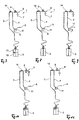
- Fassumschaltvoriques only a foam sensor 14 is provided, which is positioned at the highest point of the system. In addition, only a single three-way valve is provided so that foam is removed from the piping system only near the foam sensor.
- FIG. 7 shows with continuous lines in the inflow 2 and the outflow line 4 that the entire line system is filled with beverage.
- the beverage flows via the inflow line 2 past the foam sensor 14 to the three-way valve 11 and from there to the outlet 5, which leads to the tap (not shown).
- the FIG. 8 shows the situation in which the barrel 3 is empty. Now foam (dotted line) enters the inlet line 2 and from there to the foam sensor 14. As the foam sensor 14 detects foam, the three-way valve 11 is changed so that neither foam nor drink can reach the outlet 5.
- the FIG. 9 shows how In this situation, the foam collects below the foam sensor 14 and the lines are partly filled with foam and partly with beverage.
- FIG. 10 shows that now the valve 6 is opened, so that the foam flows to the foam outlet 8.
- the valve 6 remains open until the foam sensor 14 no longer detects foam.
- the valve 6 can also be closed with a time delay. It is advantageous if the valve 6 is repeatedly opened and closed in dependence on the foam detected on the foam detector until no more foam is detected.
- FIGS. 7 to 11 The in the FIGS. 7 to 11
- the arrangement shown can be correspondingly also for in the FIG. 6 shown cones are used with a tap of several barrels.
Landscapes
- Devices For Dispensing Beverages (AREA)
Applications Claiming Priority (1)
| Application Number | Priority Date | Filing Date | Title |
|---|---|---|---|
| DE102016014587.0A DE102016014587A1 (de) | 2016-12-08 | 2016-12-08 | Fassumschaltvorrichtung und Verfahren zum Betreiben einer Fassumschaltvorrichtung |
Publications (2)
| Publication Number | Publication Date |
|---|---|
| EP3333122A1 true EP3333122A1 (fr) | 2018-06-13 |
| EP3333122B1 EP3333122B1 (fr) | 2019-08-14 |
Family
ID=60452342
Family Applications (1)
| Application Number | Title | Priority Date | Filing Date |
|---|---|---|---|
| EP17001926.9A Active EP3333122B1 (fr) | 2016-12-08 | 2017-11-23 | Dispositif formant douille à commutateur et procédé de fonctionnement d'un dispositif dispositif formant douille à commutateur |
Country Status (2)
| Country | Link |
|---|---|
| EP (1) | EP3333122B1 (fr) |
| DE (1) | DE102016014587A1 (fr) |
Cited By (2)
| Publication number | Priority date | Publication date | Assignee | Title |
|---|---|---|---|---|
| CN110002387A (zh) * | 2019-04-09 | 2019-07-12 | 北京古点科技有限公司 | 一种消除气泡装置及饮料机 |
| EP3578505A1 (fr) | 2018-06-07 | 2019-12-11 | Günther Gruber | Module de commande d'installation de comptoir ainsi que procédé de fonctionnement d'un module de commande d'installation de comptoir |
Families Citing this family (1)
| Publication number | Priority date | Publication date | Assignee | Title |
|---|---|---|---|---|
| US12187595B2 (en) * | 2021-11-30 | 2025-01-07 | Paul McGrane | Fluid line monitoring and control assembly |
Citations (3)
| Publication number | Priority date | Publication date | Assignee | Title |
|---|---|---|---|---|
| JPH05319489A (ja) * | 1992-05-18 | 1993-12-03 | Bokuson Kogyo Kk | ビール注出装置 |
| NL1005225C1 (nl) * | 1997-02-10 | 1998-08-11 | Adrianus De Bruin | Tapinstallatie. |
| DE102007029095A1 (de) * | 2007-06-21 | 2008-12-24 | Hans Dirmeier | Leitungselement für flüssige Lebensmittel mit einem Einlass, einem Medium-Leitungsbereich und einem Auslass |
-
2016
- 2016-12-08 DE DE102016014587.0A patent/DE102016014587A1/de not_active Withdrawn
-
2017
- 2017-11-23 EP EP17001926.9A patent/EP3333122B1/fr active Active
Patent Citations (3)
| Publication number | Priority date | Publication date | Assignee | Title |
|---|---|---|---|---|
| JPH05319489A (ja) * | 1992-05-18 | 1993-12-03 | Bokuson Kogyo Kk | ビール注出装置 |
| NL1005225C1 (nl) * | 1997-02-10 | 1998-08-11 | Adrianus De Bruin | Tapinstallatie. |
| DE102007029095A1 (de) * | 2007-06-21 | 2008-12-24 | Hans Dirmeier | Leitungselement für flüssige Lebensmittel mit einem Einlass, einem Medium-Leitungsbereich und einem Auslass |
Cited By (3)
| Publication number | Priority date | Publication date | Assignee | Title |
|---|---|---|---|---|
| EP3578505A1 (fr) | 2018-06-07 | 2019-12-11 | Günther Gruber | Module de commande d'installation de comptoir ainsi que procédé de fonctionnement d'un module de commande d'installation de comptoir |
| CN110002387A (zh) * | 2019-04-09 | 2019-07-12 | 北京古点科技有限公司 | 一种消除气泡装置及饮料机 |
| CN110002387B (zh) * | 2019-04-09 | 2024-04-02 | 北京古点科技有限公司 | 一种消除气泡装置及饮料机 |
Also Published As
| Publication number | Publication date |
|---|---|
| EP3333122B1 (fr) | 2019-08-14 |
| DE102016014587A1 (de) | 2018-06-14 |
Similar Documents
| Publication | Publication Date | Title |
|---|---|---|
| DE1128185B (de) | Vorrichtung zur Entnahme von Proben aus Fluessigkeiten | |
| WO2005016814A1 (fr) | Systeme de distribution de boissons et procede pour nettoyer un systeme de distribution | |
| EP3333122B1 (fr) | Dispositif formant douille à commutateur et procédé de fonctionnement d'un dispositif dispositif formant douille à commutateur | |
| DE102004006095A1 (de) | Vorrichtung zur Erzeugung von Milchschaum | |
| EP4146367B1 (fr) | Test de passage automatise pour un panier de filtre | |
| EP2100123B1 (fr) | Dispositif et procédé d'échantillonnage automatique dans un système de réservoir de stockage relié à une tuyauterie d'alimentation en fluides de nettoyage | |
| EP0512393A1 (fr) | Méthode et appareil pour mélanger les composants d'une boisson | |
| WO2016146718A1 (fr) | Dispositif de nettoyage et procédé de fonctionnement | |
| AT518158B1 (de) | Fassumschaltvorrichtung und Verfahren zum Betreiben einer Fassumschaltvorrichtung | |
| EP2314538B1 (fr) | Dispositif et procédé de remplissage sans perte de produits mélangés en continu dans des récipients | |
| DE102006026025A1 (de) | Leitungselement für flüssige Lebensmittel und Anordnung mit einem Leitungselement | |
| DE19505229C2 (de) | Apparatur für Flüssigkeitsabgabeanlagen zum Betrieb mit unterschiedlichen Flüssigkeiten | |
| DE102007029095A1 (de) | Leitungselement für flüssige Lebensmittel mit einem Einlass, einem Medium-Leitungsbereich und einem Auslass | |
| DE2800556A1 (de) | Ventil zur entlueftung und belueftung insbesondere einer abwasserleitung | |
| DE10142092A1 (de) | Filtervorrichtung für Gartenteiche oder dergleichen | |
| DE29704794U1 (de) | Anordnung zur automatischen Reinigung von Zapfhahn, Getränkeleitung und Zapfkopf in Getränke-, insbesondere Bierzapfanlagen | |
| DE3025502C2 (de) | Vorrichtung zur Übernahme von Milch | |
| US2039006A (en) | Apparatus for dispensing beverages | |
| WO2012163843A1 (fr) | Procédé permettant de faire fonctionner une soupape d'une installation relevant du génie des procédés et transportant un produit, dispositif de soupape pourvu d'une telle soupape ainsi qu'utilisation d'une telle soupape | |
| DE2658361A1 (de) | Sicherheits-absperrventilanordnung fuer rohrleitungssysteme und- anlagen | |
| DE202015006600U1 (de) | Vorrichtung zum Befüllen zumindest eines Behälters mit einem Medium | |
| EP4414637B1 (fr) | Installation pour l'évacuation d'eaux usées, en particulier par aspiration sous vide | |
| DE673297C (de) | Zellenheisshalter | |
| DE281470C (fr) | ||
| DE293445C (fr) |
Legal Events
| Date | Code | Title | Description |
|---|---|---|---|
| PUAI | Public reference made under article 153(3) epc to a published international application that has entered the european phase |
Free format text: ORIGINAL CODE: 0009012 |
|
| STAA | Information on the status of an ep patent application or granted ep patent |
Free format text: STATUS: THE APPLICATION HAS BEEN PUBLISHED |
|
| AK | Designated contracting states |
Kind code of ref document: A1 Designated state(s): AL AT BE BG CH CY CZ DE DK EE ES FI FR GB GR HR HU IE IS IT LI LT LU LV MC MK MT NL NO PL PT RO RS SE SI SK SM TR |
|
| AX | Request for extension of the european patent |
Extension state: BA ME |
|
| STAA | Information on the status of an ep patent application or granted ep patent |
Free format text: STATUS: REQUEST FOR EXAMINATION WAS MADE |
|
| 17P | Request for examination filed |
Effective date: 20181210 |
|
| RBV | Designated contracting states (corrected) |
Designated state(s): AL AT BE BG CH CY CZ DE DK EE ES FI FR GB GR HR HU IE IS IT LI LT LU LV MC MK MT NL NO PL PT RO RS SE SI SK SM TR |
|
| GRAP | Despatch of communication of intention to grant a patent |
Free format text: ORIGINAL CODE: EPIDOSNIGR1 |
|
| STAA | Information on the status of an ep patent application or granted ep patent |
Free format text: STATUS: GRANT OF PATENT IS INTENDED |
|
| INTG | Intention to grant announced |
Effective date: 20190429 |
|
| GRAS | Grant fee paid |
Free format text: ORIGINAL CODE: EPIDOSNIGR3 |
|
| GRAA | (expected) grant |
Free format text: ORIGINAL CODE: 0009210 |
|
| STAA | Information on the status of an ep patent application or granted ep patent |
Free format text: STATUS: THE PATENT HAS BEEN GRANTED |
|
| AK | Designated contracting states |
Kind code of ref document: B1 Designated state(s): AL AT BE BG CH CY CZ DE DK EE ES FI FR GB GR HR HU IE IS IT LI LT LU LV MC MK MT NL NO PL PT RO RS SE SI SK SM TR |
|
| REG | Reference to a national code |
Ref country code: GB Ref legal event code: FG4D Free format text: NOT ENGLISH |
|
| REG | Reference to a national code |
Ref country code: CH Ref legal event code: EP Ref country code: AT Ref legal event code: REF Ref document number: 1166784 Country of ref document: AT Kind code of ref document: T Effective date: 20190815 |
|
| REG | Reference to a national code |
Ref country code: IE Ref legal event code: FG4D Free format text: LANGUAGE OF EP DOCUMENT: GERMAN |
|
| REG | Reference to a national code |
Ref country code: DE Ref legal event code: R096 Ref document number: 502017002000 Country of ref document: DE |
|
| REG | Reference to a national code |
Ref country code: CH Ref legal event code: NV Representative=s name: R.A. EGLI AND CO, PATENTANWAELTE, CH |
|
| REG | Reference to a national code |
Ref country code: NL Ref legal event code: FP |
|
| REG | Reference to a national code |
Ref country code: LT Ref legal event code: MG4D |
|
| PG25 | Lapsed in a contracting state [announced via postgrant information from national office to epo] |
Ref country code: PT Free format text: LAPSE BECAUSE OF FAILURE TO SUBMIT A TRANSLATION OF THE DESCRIPTION OR TO PAY THE FEE WITHIN THE PRESCRIBED TIME-LIMIT Effective date: 20191216 Ref country code: SE Free format text: LAPSE BECAUSE OF FAILURE TO SUBMIT A TRANSLATION OF THE DESCRIPTION OR TO PAY THE FEE WITHIN THE PRESCRIBED TIME-LIMIT Effective date: 20190814 Ref country code: NO Free format text: LAPSE BECAUSE OF FAILURE TO SUBMIT A TRANSLATION OF THE DESCRIPTION OR TO PAY THE FEE WITHIN THE PRESCRIBED TIME-LIMIT Effective date: 20191114 Ref country code: FI Free format text: LAPSE BECAUSE OF FAILURE TO SUBMIT A TRANSLATION OF THE DESCRIPTION OR TO PAY THE FEE WITHIN THE PRESCRIBED TIME-LIMIT Effective date: 20190814 Ref country code: HR Free format text: LAPSE BECAUSE OF FAILURE TO SUBMIT A TRANSLATION OF THE DESCRIPTION OR TO PAY THE FEE WITHIN THE PRESCRIBED TIME-LIMIT Effective date: 20190814 Ref country code: BG Free format text: LAPSE BECAUSE OF FAILURE TO SUBMIT A TRANSLATION OF THE DESCRIPTION OR TO PAY THE FEE WITHIN THE PRESCRIBED TIME-LIMIT Effective date: 20191114 Ref country code: LT Free format text: LAPSE BECAUSE OF FAILURE TO SUBMIT A TRANSLATION OF THE DESCRIPTION OR TO PAY THE FEE WITHIN THE PRESCRIBED TIME-LIMIT Effective date: 20190814 |
|
| PG25 | Lapsed in a contracting state [announced via postgrant information from national office to epo] |
Ref country code: ES Free format text: LAPSE BECAUSE OF FAILURE TO SUBMIT A TRANSLATION OF THE DESCRIPTION OR TO PAY THE FEE WITHIN THE PRESCRIBED TIME-LIMIT Effective date: 20190814 Ref country code: GR Free format text: LAPSE BECAUSE OF FAILURE TO SUBMIT A TRANSLATION OF THE DESCRIPTION OR TO PAY THE FEE WITHIN THE PRESCRIBED TIME-LIMIT Effective date: 20191115 Ref country code: AL Free format text: LAPSE BECAUSE OF FAILURE TO SUBMIT A TRANSLATION OF THE DESCRIPTION OR TO PAY THE FEE WITHIN THE PRESCRIBED TIME-LIMIT Effective date: 20190814 Ref country code: LV Free format text: LAPSE BECAUSE OF FAILURE TO SUBMIT A TRANSLATION OF THE DESCRIPTION OR TO PAY THE FEE WITHIN THE PRESCRIBED TIME-LIMIT Effective date: 20190814 Ref country code: RS Free format text: LAPSE BECAUSE OF FAILURE TO SUBMIT A TRANSLATION OF THE DESCRIPTION OR TO PAY THE FEE WITHIN THE PRESCRIBED TIME-LIMIT Effective date: 20190814 Ref country code: IS Free format text: LAPSE BECAUSE OF FAILURE TO SUBMIT A TRANSLATION OF THE DESCRIPTION OR TO PAY THE FEE WITHIN THE PRESCRIBED TIME-LIMIT Effective date: 20191214 |
|
| PG25 | Lapsed in a contracting state [announced via postgrant information from national office to epo] |
Ref country code: TR Free format text: LAPSE BECAUSE OF FAILURE TO SUBMIT A TRANSLATION OF THE DESCRIPTION OR TO PAY THE FEE WITHIN THE PRESCRIBED TIME-LIMIT Effective date: 20190814 |
|
| PG25 | Lapsed in a contracting state [announced via postgrant information from national office to epo] |
Ref country code: RO Free format text: LAPSE BECAUSE OF FAILURE TO SUBMIT A TRANSLATION OF THE DESCRIPTION OR TO PAY THE FEE WITHIN THE PRESCRIBED TIME-LIMIT Effective date: 20190814 Ref country code: PL Free format text: LAPSE BECAUSE OF FAILURE TO SUBMIT A TRANSLATION OF THE DESCRIPTION OR TO PAY THE FEE WITHIN THE PRESCRIBED TIME-LIMIT Effective date: 20190814 Ref country code: DK Free format text: LAPSE BECAUSE OF FAILURE TO SUBMIT A TRANSLATION OF THE DESCRIPTION OR TO PAY THE FEE WITHIN THE PRESCRIBED TIME-LIMIT Effective date: 20190814 Ref country code: IT Free format text: LAPSE BECAUSE OF FAILURE TO SUBMIT A TRANSLATION OF THE DESCRIPTION OR TO PAY THE FEE WITHIN THE PRESCRIBED TIME-LIMIT Effective date: 20190814 Ref country code: EE Free format text: LAPSE BECAUSE OF FAILURE TO SUBMIT A TRANSLATION OF THE DESCRIPTION OR TO PAY THE FEE WITHIN THE PRESCRIBED TIME-LIMIT Effective date: 20190814 |
|
| PG25 | Lapsed in a contracting state [announced via postgrant information from national office to epo] |
Ref country code: CZ Free format text: LAPSE BECAUSE OF FAILURE TO SUBMIT A TRANSLATION OF THE DESCRIPTION OR TO PAY THE FEE WITHIN THE PRESCRIBED TIME-LIMIT Effective date: 20190814 Ref country code: SM Free format text: LAPSE BECAUSE OF FAILURE TO SUBMIT A TRANSLATION OF THE DESCRIPTION OR TO PAY THE FEE WITHIN THE PRESCRIBED TIME-LIMIT Effective date: 20190814 Ref country code: IS Free format text: LAPSE BECAUSE OF FAILURE TO SUBMIT A TRANSLATION OF THE DESCRIPTION OR TO PAY THE FEE WITHIN THE PRESCRIBED TIME-LIMIT Effective date: 20200224 Ref country code: SK Free format text: LAPSE BECAUSE OF FAILURE TO SUBMIT A TRANSLATION OF THE DESCRIPTION OR TO PAY THE FEE WITHIN THE PRESCRIBED TIME-LIMIT Effective date: 20190814 |
|
| REG | Reference to a national code |
Ref country code: DE Ref legal event code: R097 Ref document number: 502017002000 Country of ref document: DE |
|
| PLBE | No opposition filed within time limit |
Free format text: ORIGINAL CODE: 0009261 |
|
| STAA | Information on the status of an ep patent application or granted ep patent |
Free format text: STATUS: NO OPPOSITION FILED WITHIN TIME LIMIT |
|
| PG2D | Information on lapse in contracting state deleted |
Ref country code: IS |
|
| PG25 | Lapsed in a contracting state [announced via postgrant information from national office to epo] |
Ref country code: LU Free format text: LAPSE BECAUSE OF NON-PAYMENT OF DUE FEES Effective date: 20191123 Ref country code: MC Free format text: LAPSE BECAUSE OF FAILURE TO SUBMIT A TRANSLATION OF THE DESCRIPTION OR TO PAY THE FEE WITHIN THE PRESCRIBED TIME-LIMIT Effective date: 20190814 |
|
| 26N | No opposition filed |
Effective date: 20200603 |
|
| REG | Reference to a national code |
Ref country code: BE Ref legal event code: MM Effective date: 20191130 |
|
| PG25 | Lapsed in a contracting state [announced via postgrant information from national office to epo] |
Ref country code: SI Free format text: LAPSE BECAUSE OF FAILURE TO SUBMIT A TRANSLATION OF THE DESCRIPTION OR TO PAY THE FEE WITHIN THE PRESCRIBED TIME-LIMIT Effective date: 20190814 |
|
| PG25 | Lapsed in a contracting state [announced via postgrant information from national office to epo] |
Ref country code: IE Free format text: LAPSE BECAUSE OF NON-PAYMENT OF DUE FEES Effective date: 20191123 |
|
| PG25 | Lapsed in a contracting state [announced via postgrant information from national office to epo] |
Ref country code: BE Free format text: LAPSE BECAUSE OF NON-PAYMENT OF DUE FEES Effective date: 20191130 |
|
| PG25 | Lapsed in a contracting state [announced via postgrant information from national office to epo] |
Ref country code: CY Free format text: LAPSE BECAUSE OF FAILURE TO SUBMIT A TRANSLATION OF THE DESCRIPTION OR TO PAY THE FEE WITHIN THE PRESCRIBED TIME-LIMIT Effective date: 20190814 |
|
| PG25 | Lapsed in a contracting state [announced via postgrant information from national office to epo] |
Ref country code: HU Free format text: LAPSE BECAUSE OF FAILURE TO SUBMIT A TRANSLATION OF THE DESCRIPTION OR TO PAY THE FEE WITHIN THE PRESCRIBED TIME-LIMIT; INVALID AB INITIO Effective date: 20171123 Ref country code: MT Free format text: LAPSE BECAUSE OF FAILURE TO SUBMIT A TRANSLATION OF THE DESCRIPTION OR TO PAY THE FEE WITHIN THE PRESCRIBED TIME-LIMIT Effective date: 20190814 Ref country code: FR Free format text: LAPSE BECAUSE OF NON-PAYMENT OF DUE FEES Effective date: 20191202 |
|
| PG25 | Lapsed in a contracting state [announced via postgrant information from national office to epo] |
Ref country code: MK Free format text: LAPSE BECAUSE OF FAILURE TO SUBMIT A TRANSLATION OF THE DESCRIPTION OR TO PAY THE FEE WITHIN THE PRESCRIBED TIME-LIMIT Effective date: 20190814 |
|
| GBPC | Gb: european patent ceased through non-payment of renewal fee |
Effective date: 20211123 |
|
| PG25 | Lapsed in a contracting state [announced via postgrant information from national office to epo] |
Ref country code: GB Free format text: LAPSE BECAUSE OF NON-PAYMENT OF DUE FEES Effective date: 20211123 |
|
| REG | Reference to a national code |
Ref country code: CH Ref legal event code: U11 Free format text: ST27 STATUS EVENT CODE: U-0-0-U10-U11 (AS PROVIDED BY THE NATIONAL OFFICE) Effective date: 20251201 |
|
| PGFP | Annual fee paid to national office [announced via postgrant information from national office to epo] |
Ref country code: NL Payment date: 20251119 Year of fee payment: 9 |
|
| PGFP | Annual fee paid to national office [announced via postgrant information from national office to epo] |
Ref country code: DE Payment date: 20251127 Year of fee payment: 9 |
|
| PGFP | Annual fee paid to national office [announced via postgrant information from national office to epo] |
Ref country code: AT Payment date: 20251120 Year of fee payment: 9 |
|
| PGFP | Annual fee paid to national office [announced via postgrant information from national office to epo] |
Ref country code: CH Payment date: 20251201 Year of fee payment: 9 |