EP3333627A1 - Bildgebungsvorrichtung - Google Patents
Bildgebungsvorrichtung Download PDFInfo
- Publication number
- EP3333627A1 EP3333627A1 EP16834841.5A EP16834841A EP3333627A1 EP 3333627 A1 EP3333627 A1 EP 3333627A1 EP 16834841 A EP16834841 A EP 16834841A EP 3333627 A1 EP3333627 A1 EP 3333627A1
- Authority
- EP
- European Patent Office
- Prior art keywords
- unit
- controller
- shake
- optical system
- correction unit
- Prior art date
- Legal status (The legal status is an assumption and is not a legal conclusion. Google has not performed a legal analysis and makes no representation as to the accuracy of the status listed.)
- Withdrawn
Links
- 238000003384 imaging method Methods 0.000 title claims abstract description 49
- 230000003287 optical effect Effects 0.000 claims abstract description 98
- 238000001514 detection method Methods 0.000 claims description 36
- 230000008859 change Effects 0.000 description 10
- 239000000758 substrate Substances 0.000 description 6
- 238000010586 diagram Methods 0.000 description 4
- 230000007423 decrease Effects 0.000 description 2
- 230000003321 amplification Effects 0.000 description 1
- 230000000903 blocking effect Effects 0.000 description 1
- 238000006243 chemical reaction Methods 0.000 description 1
- 230000004907 flux Effects 0.000 description 1
- 239000004973 liquid crystal related substance Substances 0.000 description 1
- 239000000696 magnetic material Substances 0.000 description 1
- 230000007246 mechanism Effects 0.000 description 1
- 238000012986 modification Methods 0.000 description 1
- 230000004048 modification Effects 0.000 description 1
- 238000003199 nucleic acid amplification method Methods 0.000 description 1
- 230000004044 response Effects 0.000 description 1
- 230000004043 responsiveness Effects 0.000 description 1
Images




Classifications
-
- G—PHYSICS
- G03—PHOTOGRAPHY; CINEMATOGRAPHY; ANALOGOUS TECHNIQUES USING WAVES OTHER THAN OPTICAL WAVES; ELECTROGRAPHY; HOLOGRAPHY
- G03B—APPARATUS OR ARRANGEMENTS FOR TAKING PHOTOGRAPHS OR FOR PROJECTING OR VIEWING THEM; APPARATUS OR ARRANGEMENTS EMPLOYING ANALOGOUS TECHNIQUES USING WAVES OTHER THAN OPTICAL WAVES; ACCESSORIES THEREFOR
- G03B5/00—Adjustment of optical system relative to image or object surface other than for focusing
-
- G—PHYSICS
- G03—PHOTOGRAPHY; CINEMATOGRAPHY; ANALOGOUS TECHNIQUES USING WAVES OTHER THAN OPTICAL WAVES; ELECTROGRAPHY; HOLOGRAPHY
- G03B—APPARATUS OR ARRANGEMENTS FOR TAKING PHOTOGRAPHS OR FOR PROJECTING OR VIEWING THEM; APPARATUS OR ARRANGEMENTS EMPLOYING ANALOGOUS TECHNIQUES USING WAVES OTHER THAN OPTICAL WAVES; ACCESSORIES THEREFOR
- G03B5/00—Adjustment of optical system relative to image or object surface other than for focusing
- G03B5/02—Lateral adjustment of lens
-
- H—ELECTRICITY
- H04—ELECTRIC COMMUNICATION TECHNIQUE
- H04N—PICTORIAL COMMUNICATION, e.g. TELEVISION
- H04N21/00—Selective content distribution, e.g. interactive television or video on demand [VOD]
- H04N21/40—Client devices specifically adapted for the reception of or interaction with content, e.g. set-top-box [STB]; Operations thereof
- H04N21/41—Structure of client; Structure of client peripherals
- H04N21/422—Input-only peripherals, i.e. input devices connected to specially adapted client devices, e.g. global positioning system [GPS]
- H04N21/42204—User interfaces specially adapted for controlling a client device through a remote control device; Remote control devices therefor
-
- H—ELECTRICITY
- H04—ELECTRIC COMMUNICATION TECHNIQUE
- H04N—PICTORIAL COMMUNICATION, e.g. TELEVISION
- H04N23/00—Cameras or camera modules comprising electronic image sensors; Control thereof
- H04N23/50—Constructional details
- H04N23/54—Mounting of pick-up tubes, electronic image sensors, deviation or focusing coils
-
- H—ELECTRICITY
- H04—ELECTRIC COMMUNICATION TECHNIQUE
- H04N—PICTORIAL COMMUNICATION, e.g. TELEVISION
- H04N23/00—Cameras or camera modules comprising electronic image sensors; Control thereof
- H04N23/50—Constructional details
- H04N23/55—Optical parts specially adapted for electronic image sensors; Mounting thereof
-
- H—ELECTRICITY
- H04—ELECTRIC COMMUNICATION TECHNIQUE
- H04N—PICTORIAL COMMUNICATION, e.g. TELEVISION
- H04N23/00—Cameras or camera modules comprising electronic image sensors; Control thereof
- H04N23/60—Control of cameras or camera modules
-
- H—ELECTRICITY
- H04—ELECTRIC COMMUNICATION TECHNIQUE
- H04N—PICTORIAL COMMUNICATION, e.g. TELEVISION
- H04N23/00—Cameras or camera modules comprising electronic image sensors; Control thereof
- H04N23/60—Control of cameras or camera modules
- H04N23/68—Control of cameras or camera modules for stable pick-up of the scene, e.g. compensating for camera body vibrations
- H04N23/681—Motion detection
- H04N23/6812—Motion detection based on additional sensors, e.g. acceleration sensors
-
- H—ELECTRICITY
- H04—ELECTRIC COMMUNICATION TECHNIQUE
- H04N—PICTORIAL COMMUNICATION, e.g. TELEVISION
- H04N23/00—Cameras or camera modules comprising electronic image sensors; Control thereof
- H04N23/60—Control of cameras or camera modules
- H04N23/68—Control of cameras or camera modules for stable pick-up of the scene, e.g. compensating for camera body vibrations
- H04N23/682—Vibration or motion blur correction
- H04N23/684—Vibration or motion blur correction performed by controlling the image sensor readout, e.g. by controlling the integration time
-
- H—ELECTRICITY
- H04—ELECTRIC COMMUNICATION TECHNIQUE
- H04N—PICTORIAL COMMUNICATION, e.g. TELEVISION
- H04N23/00—Cameras or camera modules comprising electronic image sensors; Control thereof
- H04N23/60—Control of cameras or camera modules
- H04N23/68—Control of cameras or camera modules for stable pick-up of the scene, e.g. compensating for camera body vibrations
- H04N23/682—Vibration or motion blur correction
- H04N23/685—Vibration or motion blur correction performed by mechanical compensation
- H04N23/687—Vibration or motion blur correction performed by mechanical compensation by shifting the lens or sensor position
-
- G—PHYSICS
- G03—PHOTOGRAPHY; CINEMATOGRAPHY; ANALOGOUS TECHNIQUES USING WAVES OTHER THAN OPTICAL WAVES; ELECTROGRAPHY; HOLOGRAPHY
- G03B—APPARATUS OR ARRANGEMENTS FOR TAKING PHOTOGRAPHS OR FOR PROJECTING OR VIEWING THEM; APPARATUS OR ARRANGEMENTS EMPLOYING ANALOGOUS TECHNIQUES USING WAVES OTHER THAN OPTICAL WAVES; ACCESSORIES THEREFOR
- G03B2205/00—Adjustment of optical system relative to image or object surface other than for focusing
- G03B2205/0007—Movement of one or more optical elements for control of motion blur
-
- G—PHYSICS
- G03—PHOTOGRAPHY; CINEMATOGRAPHY; ANALOGOUS TECHNIQUES USING WAVES OTHER THAN OPTICAL WAVES; ELECTROGRAPHY; HOLOGRAPHY
- G03B—APPARATUS OR ARRANGEMENTS FOR TAKING PHOTOGRAPHS OR FOR PROJECTING OR VIEWING THEM; APPARATUS OR ARRANGEMENTS EMPLOYING ANALOGOUS TECHNIQUES USING WAVES OTHER THAN OPTICAL WAVES; ACCESSORIES THEREFOR
- G03B2205/00—Adjustment of optical system relative to image or object surface other than for focusing
- G03B2205/0007—Movement of one or more optical elements for control of motion blur
- G03B2205/0015—Movement of one or more optical elements for control of motion blur by displacing one or more optical elements normal to the optical axis
-
- G—PHYSICS
- G03—PHOTOGRAPHY; CINEMATOGRAPHY; ANALOGOUS TECHNIQUES USING WAVES OTHER THAN OPTICAL WAVES; ELECTROGRAPHY; HOLOGRAPHY
- G03B—APPARATUS OR ARRANGEMENTS FOR TAKING PHOTOGRAPHS OR FOR PROJECTING OR VIEWING THEM; APPARATUS OR ARRANGEMENTS EMPLOYING ANALOGOUS TECHNIQUES USING WAVES OTHER THAN OPTICAL WAVES; ACCESSORIES THEREFOR
- G03B2205/00—Adjustment of optical system relative to image or object surface other than for focusing
- G03B2205/0007—Movement of one or more optical elements for control of motion blur
- G03B2205/0038—Movement of one or more optical elements for control of motion blur by displacing the image plane with respect to the optical axis
Definitions
- the present invention relates to an imaging apparatus comprising a correction unit for driving an optical lens and a correction unit for driving an image sensor.
- a camera shake correction unit that reduces blurring caused in a captured image due to a camera shake by moving an image sensor is known.
- a camera shake correction unit that reduces blurring caused in a captured image due to a camera shake by moving an optical lens is also known.
- combined use of a camera shake correction unit using lens movement and a camera shake correction unit using image sensor movement has been proposed.
- the camera of Jpn. Pat. Appln. KOKAI Publication No. 2005-128092 performs switching between a camera shake correction unit using lens movement and a camera shake correction unit using image sensor movement in accordance with the condition of the subject.
- the present invention has been made in consideration of the above circumstances, and is intended to provide an imaging apparatus comprising a correction unit for driving part of the lens of an imaging optical system and a correction unit for driving an image sensor, and capable of controlling one of the lens and the image sensor to be located at a regular fixed position relative to the other when making a high resolution correction such as a pixel shift correction.
- the image sensor correction unit 206 includes an imaging unit mounted on movable frame 2062, which serves as a second movable unit.
- the imaging unit includes, for example, an image sensor.
- the image sensor captures a subject, not shown to generate a captured image associated with the subject.
- the image sensor correction unit 206 moves the imaging unit mounted on movable frame 2062, which serves as the second movable unit, by a voice coil motor (VCM) using a coil and a magnet.
- VCM voice coil motor
- the monitor 208 is, for example, a liquid crystal display, and displays an image based on the captured image generated by the image sensor of the image sensor correction unit 206.
- the monitor 208 displays a menu screen for enabling a user to make various settings of the imaging apparatus 1.
- the monitor 208 may include a touch panel.
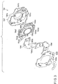
- FIG. 2 shows an assembled state of the optical system correction unit 104.
- the optical system correction unit 104 generally includes a fixed frame 1041 and a movable frame 1042.
- the optical system correction unit 104 moves the movable frame 1042 parallel on a plane (defined by the X direction and Y direction in FIG. 1 ) perpendicular to the optical axis O.
- the hall lid 1043 is an L-shaped plate member set on the main body 1042b to be opposed to the X hall element 1042e and the Y hall element 1042f.
- An X hall magnet 1043a is provided on a back surface of the hall lid 1043 at a position corresponding to the X hall element 1042e.
- a Y hall magnet 1043b is provided on the back surface of the hall lid 1043 at a position corresponding to the Y hall element 1042f.
- the position of the movable frame 1042 can be detected from the strength of the voltage signal output from the hall element by associating the stroke position of the movable frame 1042 and the output voltage of the hall element as shown in FIG. 4 .
- the movable frame 1042 can be driven to any stroke position by controlling the magnitude of the drive current applied to the X coil 1042c and the Y coil 1042d in accordance with the detected stroke position of the movable frame 1042.
- FIG. 5 is a functional block diagram showing a configuration relating to feedback control of the stroke position of the movable frame.
- the feedback controller of FIG. 5 is provided in, for example, the optical system correction controller 1061 and the image sensor correction controller 2121.
- the feedback controller of the optical system correction controller 1061 performs feedback control.
- the feedback controller 300 shown in FIG. 5 includes an amplifier 302, an A/D converter 304, a phase calculating circuit 306, a subtractor 308, a control filter 310, and a motor driver 312.
- the number of feedback controllers 300 shown in FIG. 5 is the same as that of VCMs. In the present embodiment, only the configuration corresponding to one VCM will be described.
- one of the VCMS (each formed by a set of X magnet and X coil or a set of Y magnet and Y coil) is shown as VCM 314, and one of the hall elements (X hall element or Y hall element) is shown as hall element 316.
- FIG. 6 shows a relationship between the gain of the amplifier 302 and the position detection resolution.
- the thick line in FIG. 6 indicates change of the position detection signal relative to the change of the stroke position of the movable frame in the case of high gain.
- the thin line in FIG. 6 indicates change of the position detection signal relative to the change of the stroke position of the movable frame in the case of low gain.
- the position detection signal before digitalization is indicated by a broken line and that, after digitalization, is indicated by a solid line.
- the change of the position detection signal relative to the change of the stroke position of the movable frame in the case where a high gain is set is larger than the change of the position detection signal relative to the change of the stroke position of the movable frame in the case where a low gain is set.
- the position detection resolution increases (the length of 1LSB of the digital signal decreases) as the gain increases. Therefore, when the position of the movable frame needs to be controlled with high precision, it is effective to increase the gain.
- the range of detectable stroke position is narrowed by increasing the gain. Therefore, increase of the gain makes wide range position control of the movable frame difficult. Accordingly, when a relatively wide range position control of the movable frame is required, it is effective to decrease the gain.
- the subtractor 308 outputs, to the control filter 310, a deviation signal between a drive destination position signal indicating a drive destination position of the movable frame input by, for example, controller 106 or controller 212 and the current position signal generated at the phase calculating circuit 306.
- the control filter 310 includes a digital filter formed by, for example, a combination of a plurality of infinite impulse response (IIR) filters, and outputs a drive current value based on the deviation signal output from the subtractor 308 to the motor driver 312.
- the drive current value is a value of a current that needs to be applied to a relevant coil for driving the movable frame 1042 to a destination position, and is generated by applying the digital filter to the deviation signal.
- the application of the digital filter brings the drive current value to a desired state suitable for the characteristics of the VCM 314.
- the motor driver 312 supplies a current to a relevant coil of the movable frame, based on the drive current value output from the control filter 310.
- the motor driver 312 pulse width modulation (PWM)-drives the VCM 314 (in actuality, the coil forming the VCM 314) based on the drive current value output from the control filter 310.
- the drive current value is a value indicating, for example, a duty of the PWM drive.
- FIG. 7 is a flowchart showing an operation of the imaging apparatus 1. The processing of FIG. 7 is performed by a cooperative operation of controller 106 and controller 212.
- controller 212 determines the operation mode of the image sensor correction controller 2121.
- the image sensor correction controller 2121 of the present embodiment has at least a shake correction mode, a stop mode, and a pixel shift mode.
- the image sensor correction unit 206 is controlled to capture multiple times while moving the image sensor mounted on the movable frame (movable frame 2062 of the image sensor correction unit 206), which serves as the second movable unit, by a half pitch of one pixel with high precision, and synthesize a plurality of captured images obtained by the capturing of multiple times to make a pixel shift correction for obtaining a high resolution captured image.
- the image sensor correction unit 206 functions as a pixel shift unit.
- Those three modes are set by, for example, a user's selection at the imaging apparatus 1.
- controller 212 determines that the operation mode should be the shake correction mode. In this case, the processing moves to step S102.
- controller 212 determines that the operation mode should be the pixel shift mode. In this case, the processing moves to step S106.
- controller 212 determines that the operation mode should be the stop mode. In this case, the processing moves to step S108.
- controller 212 sets the image sensor correction controller 2121 in the shake correction mode.
- controller 212 sets the gain of the amplifier 302 of the image sensor correction controller 2121 to a gain for the shake correction mode.
- the gain for the shake correction mode is smaller than the gain for the pixel shift mode.
- a small gain is set because position control in a wide range, rather than precision, is required.
- the gain is set in accordance with a required position detection resolution. For example, when the position detection resolution required for the shake correction mode is 0.6 ⁇ m/LSB, the gain of the amplifier 302 is set to provide the position detection resolution of 0.6 ⁇ m/LSB.
- controller 106 determines the operation mode of the optical system correction controller 1061.
- the optical system correction controller 1061 of the present embodiment has at least a shake correction mode, and a stop mode.
- the position of the movable frame (movable frame 1042 of the optical system correction unit 104), which serves as the first movable unit, is controlled with high precision to stop the movable frame (movable frame 1042 of the optical system correction unit 104), which serves as the first movable unit, at a predetermined regular fixed position.
- the regular fixed position is, for example, an optical center position.
- the "stop" of the stop mode of the optical system correction controller 1061 also indicates controlling the amount of movement of the movable frame to fall within a range that is regarded as giving no influence on the captured image.
- controller 212 instructs controller 106 to set the operation mode of the optical system correction controller 1061 to the shake correction mode. Based on this instruction, controller 106 determines that the operation mode should be the shake correction mode. In this case, the processing moves to step S104.
- controller 212 instructs controller 106 to set the operation mode of the optical system correction controller 1061 to the stop mode. Based on this instruction, controller 106 determines that the operation mode should be the stop mode. In this case, the processing moves to step S105.
- step S104 controller 106 sets the optical system correction controller 1061 in the shake correction mode. Then, the processing of FIG. 7 ends.
- controller 106 sets the gain of the amplifier 302 of the optical system correction controller 1061 to that for the shake correction mode.
- the gain for the shake correction mode is smaller than the gain for the stop mode.
- a small gain is set because position control in a wide range, rather than precision, is required.
- the gain is set in accordance with a required position detection resolution. For example, when the position detection resolution required for the shake correction mode is 0.6 ⁇ m/LSB, the gain of the amplifier 302 is set to provide the position detection resolution of 0.6 ⁇ m/LSB.
- shake correction using the optical system correction unit 104 and the image sensor correction unit 206 in combination is performed. This processing is well known, and a description thereof will be omitted. In the case of shake correction using the optical system correction unit 104 and the image sensor correction unit 206 in combination, it is possible to, for example, improve the number of correction stages of shake correction by cooperative control of the optical system correction unit 104 and the image sensor correction unit 206.
- controller 212 sets the image sensor correction controller 2121 in the pixel shift mode.
- controller 212 sets the gain of the amplifier 302 of the image sensor correction controller 2121 to that for the pixel shift mode.
- the gain for the pixel shift mode is higher than the gain for the shake correction mode.
- a large gain is set because high precision position control is required.
- the gain is set in accordance with a required position detection resolution. For example, when the position detection resolution required for the pixel shift mode is 0.4 ⁇ m/LSB, the gain of the amplifier 302 is set to provide the position detection resolution of 0.4 ⁇ m/LSB.
- step S107 controller 106 sets the optical system correction controller 1061 in the stop mode. Then, the processing of FIG. 7 ends.
- controller 106 sets the gain of the amplifier 302 of the optical system correction controller 1061 to that for the stop mode. As described above, the gain for the stop mode of the optical system correction controller 1061 is higher than the gain for the shake correction mode. After such setting, pixel shift capture using the image sensor correction unit 206 is performed. This processing is well known, and a description thereof will be omitted.
- controller 212 sets the image sensor correction controller 2121 in the stop mode.
- controller 212 sets the gain of the amplifier 302 of the image sensor correction controller 2121 to that for the stop mode.
- the "stop" of the stop mode of the image sensor correction controller 2121 indicates controlling the amount of movement of the movable frame to fall within a range that is regarded as giving no influence on the captured image. If such position control of the movable frame can be performed with the position detection resolution of the shake correction mode, the gain of the stop mode may be the same as that of the shake correction mode. If such position control of the movable frame cannot be performed without the position detection resolution of the pixel shift mode, the gain of the stop mode needs to be the same as that of the pixel shift mode. Of course, the gain of the stop mode may be different from either one of the gain of the shake correction mode and that of the pixel shift mode.
- step S110 controller 106 sets the optical system correction controller 1061 in the shake correction mode. Then, the processing of FIG. 7 ends. In setting of the shake correction mode, controller 106 sets the gain of the amplifier 302 of the optical system correction controller 1061 to that for the shake correction mode. After such setting, shake correction using the optical system correction unit 104 is performed. This processing is well known, and a description thereof will be omitted.
- control to stop the movable frame 1042 of the optical system correction unit 104 with high precision is performed.
- control to stop the movable frame causes a shake of the movable frame within the range of a tiny deviation amount.
- stop control with an increased position detection resolution enables stopping the movable frame with the same precision as when mechanically fixing the movable frame. Accordingly, pixel shift by the image sensor correction unit 206 is performed with high precision.
- the image sensor correction unit 206 is stopped by the feedback control of the VCM in the stop mode of the image sensor correction controller 2121.
- the image sensor correction unit 206 may be configured to be stopped by a mechanical mechanism in the stop mode of the image sensor correction controller 2121.
- a pixel shift correction is made by using the image sensor correction unit 206.
- the pixel shift correction may be performed by using the optical system correction unit 104.
- the gain is set to provide a high position detection resolution in the stop mode of the image sensor correction controller 2121.
Landscapes
- Engineering & Computer Science (AREA)
- Multimedia (AREA)
- Signal Processing (AREA)
- Physics & Mathematics (AREA)
- General Physics & Mathematics (AREA)
- Human Computer Interaction (AREA)
- Studio Devices (AREA)
- Adjustment Of Camera Lenses (AREA)
Applications Claiming Priority (2)
| Application Number | Priority Date | Filing Date | Title |
|---|---|---|---|
| JP2015157105A JP6614852B2 (ja) | 2015-08-07 | 2015-08-07 | 撮像装置 |
| PCT/JP2016/062385 WO2017026144A1 (ja) | 2015-08-07 | 2016-04-19 | 撮像装置 |
Publications (2)
| Publication Number | Publication Date |
|---|---|
| EP3333627A1 true EP3333627A1 (de) | 2018-06-13 |
| EP3333627A4 EP3333627A4 (de) | 2019-01-30 |
Family
ID=57983125
Family Applications (1)
| Application Number | Title | Priority Date | Filing Date |
|---|---|---|---|
| EP16834841.5A Withdrawn EP3333627A4 (de) | 2015-08-07 | 2016-04-19 | Bildgebungsvorrichtung |
Country Status (5)
| Country | Link |
|---|---|
| US (1) | US9883107B2 (de) |
| EP (1) | EP3333627A4 (de) |
| JP (1) | JP6614852B2 (de) |
| CN (1) | CN106575071B (de) |
| WO (1) | WO2017026144A1 (de) |
Families Citing this family (10)
| Publication number | Priority date | Publication date | Assignee | Title |
|---|---|---|---|---|
| WO2019065822A1 (ja) * | 2017-09-28 | 2019-04-04 | 富士フイルム株式会社 | 撮像装置、その作動方法および作動プログラム |
| CN116347237A (zh) | 2018-06-29 | 2023-06-27 | Lg伊诺特有限公司 | 相机装置和光学仪器 |
| JP6841979B2 (ja) * | 2018-06-29 | 2021-03-10 | 富士フイルム株式会社 | レンズ鏡筒及び撮像装置 |
| JP6872080B2 (ja) * | 2018-07-27 | 2021-05-19 | 富士フイルム株式会社 | 撮像装置 |
| JP7304193B2 (ja) | 2019-04-10 | 2023-07-06 | Omデジタルソリューションズ株式会社 | 追尾装置および追尾方法 |
| JP7500200B2 (ja) * | 2020-01-15 | 2024-06-17 | キヤノン株式会社 | 撮像装置、ブレ補正方法およびプログラム |
| US12109059B2 (en) * | 2020-05-19 | 2024-10-08 | Konica Minolta, Inc. | Dynamic analysis system, correction apparatus, storage medium, and dynamic imaging apparatus |
| US20230209220A1 (en) * | 2020-06-17 | 2023-06-29 | Sony Group Corporation | Image processing device, image processing method, and image processing program |
| WO2023008804A1 (ko) * | 2021-07-26 | 2023-02-02 | 엘지이노텍 주식회사 | 카메라 장치 및 광학기기 |
| US20240282228A1 (en) * | 2023-02-17 | 2024-08-22 | Tencent America LLC | Near eye display |
Family Cites Families (25)
| Publication number | Priority date | Publication date | Assignee | Title |
|---|---|---|---|---|
| JP2989364B2 (ja) * | 1992-03-12 | 1999-12-13 | シャープ株式会社 | 画像処理装置及び画像処理方法 |
| JPH07287268A (ja) * | 1994-04-19 | 1995-10-31 | Canon Inc | 撮像装置 |
| JPH11266391A (ja) * | 1998-03-17 | 1999-09-28 | Canon Inc | 撮像装置 |
| JP2000013670A (ja) * | 1998-06-22 | 2000-01-14 | Canon Inc | 撮像装置及び撮像装置の制御方法 |
| JP2001313867A (ja) * | 2000-05-01 | 2001-11-09 | Ricoh Co Ltd | デジタルカメラ |
| JP4567313B2 (ja) | 2003-10-21 | 2010-10-20 | オリンパス株式会社 | カメラ |
| JP2005189654A (ja) * | 2003-12-26 | 2005-07-14 | Konica Minolta Photo Imaging Inc | 手振れ補正機構を備えたカメラ |
| JP4247622B2 (ja) * | 2004-08-19 | 2009-04-02 | ソニー株式会社 | レンズ位置検出装置およびレンズ鏡筒並びに撮像装置 |
| JP2006128780A (ja) | 2004-10-26 | 2006-05-18 | Konica Minolta Photo Imaging Inc | デジタルカメラ |
| JP2007028008A (ja) * | 2005-07-13 | 2007-02-01 | Konica Minolta Photo Imaging Inc | 撮像装置、撮像システム及びその動作プログラム |
| JP4900939B2 (ja) * | 2006-11-28 | 2012-03-21 | キヤノン株式会社 | 撮像装置の制御方法 |
| JP5028574B2 (ja) * | 2007-08-10 | 2012-09-19 | 株式会社メガチップス | デジタルカメラシステム |
| JP5242151B2 (ja) * | 2007-12-21 | 2013-07-24 | セミコンダクター・コンポーネンツ・インダストリーズ・リミテッド・ライアビリティ・カンパニー | 振動補正制御回路及びそれを備えた撮像装置 |
| JP5501119B2 (ja) * | 2010-06-29 | 2014-05-21 | キヤノン株式会社 | 撮像装置およびその制御方法 |
| JP5269143B2 (ja) * | 2010-07-16 | 2013-08-21 | キヤノン株式会社 | 像ブレ補正装置及びその制御方法及び撮像装置 |
| JP2012098493A (ja) * | 2010-11-02 | 2012-05-24 | Canon Inc | 撮像装置 |
| TWI488498B (zh) * | 2010-12-01 | 2015-06-11 | Altek Corp | 多重防手震系統及其方法 |
| JP5780818B2 (ja) * | 2011-04-21 | 2015-09-16 | オリンパス株式会社 | 駆動装置およびそれを用いた画像装置 |
| JP2013074337A (ja) * | 2011-09-26 | 2013-04-22 | Canon Inc | 撮像装置、画像処理装置、画像処理方法及びプログラム |
| JP5913960B2 (ja) * | 2011-12-21 | 2016-05-11 | キヤノン株式会社 | 防振制御装置及びその制御方法、及び撮像装置 |
| JP2014006340A (ja) * | 2012-06-22 | 2014-01-16 | Sony Corp | 像振れ補正装置と像振れ補正方法および撮像装置 |
| JP2015102775A (ja) * | 2013-11-27 | 2015-06-04 | キヤノン株式会社 | 像振れ補正装置およびその制御方法 |
| JP6448184B2 (ja) * | 2013-11-27 | 2019-01-09 | キヤノン株式会社 | 像振れ補正装置およびその制御方法 |
| JP6454869B2 (ja) * | 2014-03-24 | 2019-01-23 | パナソニックIpマネジメント株式会社 | 撮像装置 |
| JP2015194712A (ja) * | 2014-03-28 | 2015-11-05 | パナソニックIpマネジメント株式会社 | 撮像装置 |
-
2015
- 2015-08-07 JP JP2015157105A patent/JP6614852B2/ja active Active
-
2016
- 2016-04-19 CN CN201680002022.9A patent/CN106575071B/zh not_active Expired - Fee Related
- 2016-04-19 WO PCT/JP2016/062385 patent/WO2017026144A1/ja not_active Ceased
- 2016-04-19 EP EP16834841.5A patent/EP3333627A4/de not_active Withdrawn
- 2016-12-07 US US15/372,353 patent/US9883107B2/en not_active Expired - Fee Related
Also Published As
| Publication number | Publication date |
|---|---|
| US20170085799A1 (en) | 2017-03-23 |
| CN106575071B (zh) | 2019-06-04 |
| EP3333627A4 (de) | 2019-01-30 |
| JP6614852B2 (ja) | 2019-12-04 |
| JP2017037130A (ja) | 2017-02-16 |
| WO2017026144A1 (ja) | 2017-02-16 |
| CN106575071A (zh) | 2017-04-19 |
| US9883107B2 (en) | 2018-01-30 |
Similar Documents
| Publication | Publication Date | Title |
|---|---|---|
| US9883107B2 (en) | Imaging apparatus | |
| JP6579609B2 (ja) | カメラシステム、そのブレ補正方法、及びカメラボディ | |
| JP4647273B2 (ja) | ステージ駆動機構 | |
| US8111295B2 (en) | Image stabilizer and optical instrument therewith | |
| US9769384B2 (en) | Imaging apparatus capable of detecting position of movable image pickup device at first resolving power and at second resolving power higher than first resolving power and, at which second resolving power, deviation amount is less than or equal to pixel shift amount | |
| JP4540354B2 (ja) | 像ブレ補正装置 | |
| US20170019599A1 (en) | Photographing apparatus, photographing method and program | |
| JP5871657B2 (ja) | 光学機器 | |
| CN1667482B (zh) | 抗抖动装置 | |
| US9749538B2 (en) | Imaging apparatus | |
| US10812723B2 (en) | Imaging device and imaging control method capable of preventing camera shake | |
| US9392161B2 (en) | Imaging apparatus | |
| JP2009210921A (ja) | 像ぶれ補正装置、レンズ鏡筒装置及びカメラ装置 | |
| JP4530691B2 (ja) | 像ブレ補正装置 | |
| JP4598465B2 (ja) | 撮像素子支持機構 | |
| JP4679170B2 (ja) | 像ブレ補正装置 | |
| JP5820667B2 (ja) | 光学式像振れ補正機構 | |
| JP4875971B2 (ja) | 撮影装置及びその調整方法 | |
| JP5293947B2 (ja) | 撮像装置 | |
| JP7086618B2 (ja) | 撮像装置およびその制御方法 | |
| JP2009282444A (ja) | 振れ補正装置および撮影装置 | |
| JP2015050643A (ja) | 撮影装置及びその調整制御方法 | |
| JP2009210922A (ja) | 像ぶれ補正装置、レンズ鏡筒装置及び撮像装置 | |
| JP2010164985A (ja) | 像ぶれ補正装置、レンズ鏡筒装置及びカメラ装置 | |
| JP2016028305A (ja) | 光学機器 |
Legal Events
| Date | Code | Title | Description |
|---|---|---|---|
| STAA | Information on the status of an ep patent application or granted ep patent |
Free format text: STATUS: THE INTERNATIONAL PUBLICATION HAS BEEN MADE |
|
| PUAI | Public reference made under article 153(3) epc to a published international application that has entered the european phase |
Free format text: ORIGINAL CODE: 0009012 |
|
| STAA | Information on the status of an ep patent application or granted ep patent |
Free format text: STATUS: REQUEST FOR EXAMINATION WAS MADE |
|
| 17P | Request for examination filed |
Effective date: 20180228 |
|
| AK | Designated contracting states |
Kind code of ref document: A1 Designated state(s): AL AT BE BG CH CY CZ DE DK EE ES FI FR GB GR HR HU IE IS IT LI LT LU LV MC MK MT NL NO PL PT RO RS SE SI SK SM TR |
|
| AX | Request for extension of the european patent |
Extension state: BA ME |
|
| DAV | Request for validation of the european patent (deleted) | ||
| DAX | Request for extension of the european patent (deleted) | ||
| A4 | Supplementary search report drawn up and despatched |
Effective date: 20190107 |
|
| RIC1 | Information provided on ipc code assigned before grant |
Ipc: G03B 5/00 20060101AFI20181221BHEP Ipc: G03B 5/04 20060101ALI20181221BHEP Ipc: H04N 5/225 20060101ALI20181221BHEP Ipc: H04N 5/44 20110101ALI20181221BHEP Ipc: H04N 5/232 20060101ALI20181221BHEP |
|
| STAA | Information on the status of an ep patent application or granted ep patent |
Free format text: STATUS: THE APPLICATION IS DEEMED TO BE WITHDRAWN |
|
| 18D | Application deemed to be withdrawn |
Effective date: 20190806 |