EP3334184B1 - Capteur acoustique et transducteur capacitif - Google Patents
Capteur acoustique et transducteur capacitif Download PDFInfo
- Publication number
- EP3334184B1 EP3334184B1 EP17198739.9A EP17198739A EP3334184B1 EP 3334184 B1 EP3334184 B1 EP 3334184B1 EP 17198739 A EP17198739 A EP 17198739A EP 3334184 B1 EP3334184 B1 EP 3334184B1
- Authority
- EP
- European Patent Office
- Prior art keywords
- electrode film
- back plate
- vibration electrode
- vibration
- acoustic sensor
- Prior art date
- Legal status (The legal status is an assumption and is not a legal conclusion. Google has not performed a legal analysis and makes no representation as to the accuracy of the status listed.)
- Active
Links
Images







Classifications
-
- H—ELECTRICITY
- H04—ELECTRIC COMMUNICATION TECHNIQUE
- H04R—LOUDSPEAKERS, MICROPHONES, GRAMOPHONE PICK-UPS OR LIKE ACOUSTIC ELECTROMECHANICAL TRANSDUCERS; ELECTRIC HEARING AIDS; PUBLIC ADDRESS SYSTEMS
- H04R9/00—Transducers of moving-coil, moving-strip, or moving-wire type
- H04R9/08—Microphones
-
- H—ELECTRICITY
- H04—ELECTRIC COMMUNICATION TECHNIQUE
- H04R—LOUDSPEAKERS, MICROPHONES, GRAMOPHONE PICK-UPS OR LIKE ACOUSTIC ELECTROMECHANICAL TRANSDUCERS; ELECTRIC HEARING AIDS; PUBLIC ADDRESS SYSTEMS
- H04R19/00—Electrostatic transducers
- H04R19/04—Microphones
-
- H—ELECTRICITY
- H04—ELECTRIC COMMUNICATION TECHNIQUE
- H04R—LOUDSPEAKERS, MICROPHONES, GRAMOPHONE PICK-UPS OR LIKE ACOUSTIC ELECTROMECHANICAL TRANSDUCERS; ELECTRIC HEARING AIDS; PUBLIC ADDRESS SYSTEMS
- H04R19/00—Electrostatic transducers
- H04R19/005—Electrostatic transducers using semiconductor materials
-
- B—PERFORMING OPERATIONS; TRANSPORTING
- B81—MICROSTRUCTURAL TECHNOLOGY
- B81B—MICROSTRUCTURAL DEVICES OR SYSTEMS, e.g. MICROMECHANICAL DEVICES
- B81B3/00—Devices comprising flexible or deformable elements, e.g. comprising elastic tongues or membranes
- B81B3/0064—Constitution or structural means for improving or controlling the physical properties of a device
- B81B3/0067—Mechanical properties
- B81B3/0072—For controlling internal stress or strain in moving or flexible elements, e.g. stress compensating layers
-
- H—ELECTRICITY
- H04—ELECTRIC COMMUNICATION TECHNIQUE
- H04R—LOUDSPEAKERS, MICROPHONES, GRAMOPHONE PICK-UPS OR LIKE ACOUSTIC ELECTROMECHANICAL TRANSDUCERS; ELECTRIC HEARING AIDS; PUBLIC ADDRESS SYSTEMS
- H04R19/00—Electrostatic transducers
- H04R19/01—Electrostatic transducers characterised by the use of electrets
-
- B—PERFORMING OPERATIONS; TRANSPORTING
- B81—MICROSTRUCTURAL TECHNOLOGY
- B81B—MICROSTRUCTURAL DEVICES OR SYSTEMS, e.g. MICROMECHANICAL DEVICES
- B81B2201/00—Specific applications of microelectromechanical systems
- B81B2201/02—Sensors
- B81B2201/0257—Microphones or microspeakers
-
- B—PERFORMING OPERATIONS; TRANSPORTING
- B81—MICROSTRUCTURAL TECHNOLOGY
- B81B—MICROSTRUCTURAL DEVICES OR SYSTEMS, e.g. MICROMECHANICAL DEVICES
- B81B3/00—Devices comprising flexible or deformable elements, e.g. comprising elastic tongues or membranes
- B81B3/0018—Structures acting upon the moving or flexible element for transforming energy into mechanical movement or vice versa, i.e. actuators, sensors, generators
- B81B3/0021—Transducers for transforming electrical into mechanical energy or vice versa
-
- H—ELECTRICITY
- H04—ELECTRIC COMMUNICATION TECHNIQUE
- H04R—LOUDSPEAKERS, MICROPHONES, GRAMOPHONE PICK-UPS OR LIKE ACOUSTIC ELECTROMECHANICAL TRANSDUCERS; ELECTRIC HEARING AIDS; PUBLIC ADDRESS SYSTEMS
- H04R1/00—Details of transducers, loudspeakers or microphones
- H04R1/20—Arrangements for obtaining desired frequency or directional characteristics
- H04R1/22—Arrangements for obtaining desired frequency or directional characteristics for obtaining desired frequency characteristic only
- H04R1/28—Transducer mountings or enclosures modified by provision of mechanical or acoustic impedances, e.g. resonator, damping means
- H04R1/2807—Enclosures comprising vibrating or resonating arrangements
- H04R1/2815—Enclosures comprising vibrating or resonating arrangements of the bass reflex type
- H04R1/2823—Vents, i.e. ports, e.g. shape thereof or tuning thereof with damping material
-
- H—ELECTRICITY
- H04—ELECTRIC COMMUNICATION TECHNIQUE
- H04R—LOUDSPEAKERS, MICROPHONES, GRAMOPHONE PICK-UPS OR LIKE ACOUSTIC ELECTROMECHANICAL TRANSDUCERS; ELECTRIC HEARING AIDS; PUBLIC ADDRESS SYSTEMS
- H04R19/00—Electrostatic transducers
-
- H—ELECTRICITY
- H04—ELECTRIC COMMUNICATION TECHNIQUE
- H04R—LOUDSPEAKERS, MICROPHONES, GRAMOPHONE PICK-UPS OR LIKE ACOUSTIC ELECTROMECHANICAL TRANSDUCERS; ELECTRIC HEARING AIDS; PUBLIC ADDRESS SYSTEMS
- H04R2201/00—Details of transducers, loudspeakers or microphones covered by H04R1/00 but not provided for in any of its subgroups
- H04R2201/003—Mems transducers or their use
Definitions
- the present invention relates to an acoustic sensor having a capacitive transducer housed in a casing, the capacitive transducer being configured in a capacitor structure formed by the MEMS technique and including a vibration electrode film and a back plate.
- an ECM Electronic Condenser Microphone
- MEMS Micro Electro Mechanical Systems
- Some of the acoustic sensors as described above house a capacitive transducer having achieved a configuration by using the MEMS technique, the configuration being where a vibration electrode film that vibrates under pressure is disposed facing a back plate spaced from the electrode film via a void.
- the configuration of the capacitive transducer as thus described can be achieved, for example, by the following step: forming on a silicon substrate a vibration electrode film and a sacrifice layer such as to cover the vibration electrode; forming a back plate on the sacrifice layer; and removing the sacrifice layer.
- the capacitive transducer inter alia composed of a vibration electrode film and a back plate
- the thickness of the transducer is reduced and the vibration electrode film is liable to be greatly deformed and damaged when excessive pressure acts thereon, or in some other cases.
- Such disadvantage may occur, for example, in a case where large sound pressure is applied into a casing (package) having a pressure hole while the capacitive transducer is housed in the casing. It may also occur in a case where air is blown to the pressure hole of the casing in a package process, or in a case where the capacitive transducer, housed in the casing, falls. This also applies to a case where large sound pressure is applied or air is blown to a mobile electronic device such as a smart phone which includes the capacitive transducer housed in the casing, or a case where the device is dropped.
- the vibration electrode film is greatly deformed to the back plate side (opposite the pressure hole) or the substrate side. At this point, the vibration electrode film may be damaged by coming into contact with the back plate or the substrate.
- the air having entered the capacitive transducer from the pressure hole passes through a gap between the vibration electrode film and the semiconductor substrate or the back plate and/or an opening of the semiconductor substrate or a sound hole of the back plate and gets more deeply into the casing, while deforming the vibration electrode film, to increase the pressure in the casing.
- the pressure in the casing may cause excessive deformation of the vibration electrode film to the pressure hole side and damage on the vibration electrode film.
- US 2014/0126762 A1 discloses measures for dynamically regulating the microphone sensitivity of a MEMS microphone component at low frequencies by way of variable roll-off behavior.
- the micromechanical microphone structure of the component which is implemented in a layer structure on a semiconductor substrate, encompasses an acoustically active diaphragm having leakage openings which spans a sound opening in the substrate back side, and a stationary acoustically permeable counterelement having through openings which is disposed in the layer structure above/below the diaphragm.
- the component furthermore encompasses a capacitor assemblage for signal sensing, having at least one deflectable electrode on the diaphragm and at least one stationary electrode on the counterelement, and an arrangement for implementing a relative motion between the diaphragm and counterelement parallel to the layer planes.
- the counterelement is equipped with a stop structure which is designed so that the number of leakage openings in the diaphragm, that are overlapped by the stop structure, depends on the relative position between the diaphragm and the counterpart.
- the stop structure can be used as an overload protector in the operating mode.
- US 2014/0319629 A1 discloses measures for increasing the resistance to compression of a component having a micromechanical microphone pattern.
- the microphone pattern of such a component is implemented in a layer construction on a semiconductor substrate and includes at least one acoustically active diaphragm, which spans a sound hole on the substrate backside, and a stationary acoustically penetrable counterelement having through hole openings, which is situated above/below the diaphragm in the layer construction.
- At least one outflow channel is developed which makes possible a rapid pressure equalization between the two sides of the diaphragm.
- at least one controllable closing element is provided, with which the at least one outflow channel is optionally able to be opened or closed.
- EP 2 386 840 A1 discloses an acoustic sensor in which sticking of a diaphragm can be prevented and also in which the diaphragm is less likely to break by impact when the sensor is dropped.
- a diaphragm for sensing sound pressure faces a back plate inducing a plate portion and a fixed electrode film to form a capacitance type acoustic sensor.
- the back plate is opened with acoustic holes for passing vibration, and is arranged with a plurality of stoppers in a projecting manner on a surface facing the diaphragm.
- the stopper arranged in an outer peripheral area of the back plate has a small diameter, and the stopper (42a) arranged in an internal area has a large diameter.
- the present invention has been made in view of such circumstances as above, and is to particularly prevent internal pressure in a casing that houses a capacitive transducer from excessively increasing due to compressed air flown in through a pressure hole of an acoustic sensor comprising the casing, and to prevent a vibration electrode film from being damaged by being excessively deformed by the pressure. That is, an object of the present invention is to provide a technique by which, when excessive pressure acts on an acoustic sensor, an increase in pressure in its casing is prevented to suppress excessive deformation of a vibration electrode film of a capacitive transducer housed in the casing.
- Fig. 1 is a perspective view illustrating an example of a conventional acoustic sensor 1 manufactured by the MEMS technique.
- Fig. 2 is an exploded perspective view illustrating an example of an internal structure of the acoustic sensor 1.
- the acoustic sensor 1 is a laminated body formed by laminating an insulating film 4, a vibration electrode film (diaphragm) 5, and a back plate 7 on the top surface of a silicon substrate (hereinafter also referred to simply as a substrate) 3 provided with a back chamber 2.
- the back plate 7 has a structure where a fixed electrode film 8 is formed on a fixed plate 6, and is formed by disposing the fixed electrode film 8 on the fixed plate 6 on the silicon substrate 3 side.
- Sound holes are provided all over the fixed plate 6 of the back plate 7 as a large number of punched holes (each of meshed points on the fixed plate 6 illustrated in Fig. 2 corresponds to each of the sound holes). Further, a fixed electrode pad 10 for acquiring an output signal is provided at one of four corners of the fixed electrode film 8.
- the silicon substrate 3 can be formed by a single crystal silicon, for example.
- the vibration electrode film 5 can be formed by conductive polycrystal silicon, for example.
- the vibration electrode film 5 is a substantially rectangular thin film, in which fixed parts 12 are provided at four corners of a vibration part 11, having a substantially quadrilateral shape, that vibrates.
- the vibration electrode film 5 is disposed on the top surface of the silicon substrate 3 so as to cover the back chamber 2, and is fixed to the silicon substrate 3 at the four fixed parts 12 as anchor parts.
- the vibration part 11 of the vibration electrode film 5 reacts sensitively to sound pressure to vibrate vertically.
- the vibration electrode film 5 is not in contact with the silicon substrate 3 or the back plate 7 in a place other than the four fixed parts 12. This allows smoother vertical vibration of the vibration electrode film 5 after sensitive reaction to sound pressure. Further, a vibrating membrane electrode pad 9 is provided in one of the fixed parts 12 at the four corners of the vibration part 11.
- the fixed electrode film 8 provided in the back plate 7 is provided so as to correspond to the vibrating portion of the vibration electrode film 5 except for the fixed parts 12 at the four corners. This is because the fixed parts 12 at the four corners of the vibration electrode film 5 do not react sensitively to sound pressure to vibrate and hence capacitance between the vibration electrode film 5 and the fixed electrode film 8 remains unchanged.
- the sound passes through the sound hole to apply sound pressure to the vibration electrode film 5. That is, sound pressure is applied to the vibration electrode film 5 through this sound hole. Further, providing the sound hole can facilitate air in an air gap between the back plate 7 and the vibration electrode film 5 to escape to the outside, to reduce thermal noise, leading to noise reduction.
- the vibration electrode film 5 vibrates upon receipt of sound, and the distance between the vibration electrode film 5 and the fixed electrode film 8 changes.
- capacitance between the vibration electrode film 5 and the fixed electrode film 8 changes.
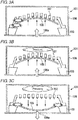
- FIGs. 3A to 3C are schematic views describing the case of excessive pressure acting on the acoustic sensor 1.
- the pressure acts on a vibration electrode film 105 from a pressure hole 106a provided at the bottom surface of a package 106 as the casing.
- the vibration electrode film 105 is greatly deformed to the back plate 107 side (opposite the pressure hole 106a), and the vibration electrode film 105 comes into contact with the back plate 107.
- the vibration electrode film 105 may be damaged at that time.
- the air having flown in from the pressure hole 106a in the above process passes through the gap between the vibration electrode film 105 and the back plate 107, further passes through a sound hole 107a of the back plate 107, and gets more deeply into the casing, to be compressed. Since this increases the pressure in the package 106, when the inflow of the air is ended, the increase in the pressure in the package 106 may then cause large deformation of the vibration electrode film 105 to the side opposite the back plate 107 (to the pressure hole 106a side), causing damage on the vibration electrode film 105. The same kind of damage can occur, for example, in a case where the acoustic sensor 1 falls or some other case in addition to the case where excessive air pressure acts on the acoustic sensor 1.
- Figs. 4A and 4B are considered. That is, as illustrated in Fig. 4A , by eliminating the sound hole 107a in a portion in the back plate 107, the portion facing the vicinity of the end of the vibration electrode film 105, it is possible to make it difficult for the air to pass through the back plate 107 via the sound hole 107a when excessive pressure acts from the pressure hole 106a.
- a plurality of projections are provided in the back plate, each projection of the plurality of projections cylindrically projecting to the vibration electrode film side so as to enclose respective sound holes of the back plate.
- the vibration electrode film is deformed to the back plate side, the vibration electrode film abuts with the tips of the projections to block the sound hole and prevent passage of the air through the sound hole and through the back plate, and thereby prevent an increase in the pressure in the package.
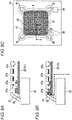
- Figs. 5A to 5C are views for describing a structure of the vicinity of a back plate 27 and a vibration electrode film 25 in the first embodiment.
- Fig. 5A is a sectional view illustrating a state before excessive pressure acts
- Fig. 5B is a sectional view illustrating a state where the excessive pressure has acted
- Fig. 5C is a plan view. Note that Figs. 5A and 5B are sectional views along an X-X cross section indicated in Fig. 5C .
- Numeral 23 denotes a substrate
- numeral 29 denotes a vibrating membrane electrode pad
- numeral 30 denotes a fixed electrode pad
- numeral 31 denotes a vibration part in the vibration electrode film 25
- numeral 32 denotes a fixed part in the vibration electrode film 25.
- a projection 27c having a cylindrical shape is provided in the back plate 27 so as to enclose a sound hole 27a close to the end of the vibration electrode film 25 among sound holes 27a in the back plate 27.
- the vibration electrode film 25 abuts with the projection 27c to block the sound hole 27a, and can thus prevent the air from passing through the sound hole 27a to suppress the increase in the internal pressure of the package in terms of a region close to the end of the vibration electrode film 25.
- the presence of the projection 27c makes it difficult for the air to get into the gap between the back plate 27 and the vibration electrode film 25, and to reach the sound hole 27a disposed in a region close to the center of the vibration electrode film 25. It is thereby possible to prevent the air from passing through the sound hole 27a in the region to suppress the increase in the internal pressure of the package.
- the projection 27c may be provided at the sound hole 27a in a region A enclosing the vibration part 31 of the vibration electrode film 25, indicated by a dotted line in Fig. 5C , or may be provided at the sound hole 17a in a region extended in the center of the vibration part 31.
- the projection 27c may also be provided at the sound holes 27a in the whole region of the vibration part 31. Further, among the sound holes 27a in the above region, the projection 27c may be provided at each of all the sound holes 27a, or may be provided at each of some of the sound holes 27a.
- the size of the region provided with the projection 27c and the number of sound holes 27a provided with the projection 27c may be appropriately decided based on the degree of increase in the pressure in the package, the degree of occurrence of sticking, and the like, when excessive pressure acts on the acoustic sensor 1.
- Figs. 6A to 6C illustrate enlarged views of the sound hole 27a and the projection 27c.
- Fig. 6A is a plan view
- Fig. 6B is a Y-Y sectional view.
- the projection 27c is provided so as to enclose the sound hole 27a in a plan view, and has a cylindrical shape when the sound hole 27a has a circular shape.
- wall-shaped walls 27e link the projections 27c having a cylindrical shape as illustrated in the plan view of Fig. 6C .
- the projection 27c and the wall 27e correspond to the flow path cutoff part and the flow path inhibition part in the present invention.
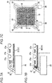
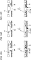
- Figs. 7A to 7C are views for describing a structure of the vicinity of the back plate 27 and the vibration electrode film 25.
- Fig. 7A is a sectional view illustrating a state before excessive pressure acts
- Fig. 7B is a sectional view illustrating a state where the excessive pressure has acted
- Fig. 7C is a plan view. Note that Figs. 7A and 7B are sectional views along an X-X cross section indicated in Fig. 7C .
- a wall 27d is provided so as to surround a region, which is a portion facing the vibration part 31 of the vibration electrode film 25 and in which the sound holes 27a are distributed, in the back plate 27.
- the vibration part 31 of the vibration electrode film 25 abuts with the tip of the wall 27d to cut off a flow path for the air (inhibit the flow of the air) toward the region where the sound holes 27a are distributed in the back plate 27. It is thereby possible to prevent the air from passing through the sound hole 27a to suppress the increase in the pressure in the package.
- the wall 27d may be provided so as to surround a region B including all the sound holes 27a in Fig. 7C , or some of the sound holes 27a may be distributed outside the region surrounded by the wall 27d.
- the wall 27d may be provided so as to surround the whole of the vibration electrode film 25 including the fixed portion 32, as illustrated in Fig. 8C .
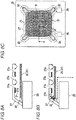
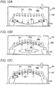
- Figs. 9A to 9C are views for describing a structure of the vicinity of the back plate 27 and the vibration electrode film 25.
- Fig. 9A is a sectional view illustrating a state before excessive pressure acts
- Fig. 9B is a sectional view illustrating a state where the excessive pressure has acted
- Fig. 9C is a plan view. Note that Figs. 9A and 9B are sectional views along an X-X cross section indicated in Fig. 9C . As illustrated in Fig.
- a projection 25a is provided in a position where each of the sound holes 27a disposed in the facing back plate 27 can be blocked in the vicinity of the end of the vibration part 31 of the vibration electrode film 25. That is, in a plan view, there has been provided the projection 25a having such a cross section in a columnar shape as to include each of the sound holes 27a.
- the projection 25a provided in the vibration electrode film 25 can block particularly the sound hole 27a disposed in a portion facing the vicinity of the end of the vibration part 31 of the vibration electrode film 25, which tends to be a flow path for the air. It is thereby possible to block the sound hole 27a disposed in the portion facing the vicinity of the end of the vibration part 31 of the vibration electrode film 25, and also possible to cut off a flow path for the air (inhibit the flow of the air) flowing into the gap between the vibration electrode film 25 and back plate 27 on the center side of the vibration electrode film 25. It is thereby possible to more efficiently prevent the air from passing through the sound hole 27a to suppress the increase in the pressure in the package.
- the projection 25a may be provided at the sound hole 27a in a region A enclosing the vibration part 31 of the vibration electrode film 25, indicated by a dotted line in Fig. 9C , or may be provided at the sound hole 27a in a region extended in the center of the vibration part 31.
- the projection 25a may be provided at each of the sound holes 27a facing the whole region of the vibration part 31 (i.e., at each of all the sound holes 27a disposed in the back plate 27). Further, among the sound holes 27a in the above region, the projection 25a may be provided at each of all the sound holes 27a, or may be provided at each of some of the extracted sound holes 27a.
- the size of the region provided with the projection 25a and the number of sound holes 27a provided with the projection 25a may be appropriately decided based on the degree of increase in the pressure in the package, the degree of occurrence of sticking, and the like, when excessive pressure acts on the acoustic sensor 1.
- the projection 25a having a columnar shape is provided in the vibration electrode film 25, the projection 25a being able to block each of the sound holes 27a in the facing back plate 27.
- the projection 25a may have a columnar shape being able to block a plurality of sound holes 27a.
- a wall is provided so as to surround at least a part of the vibration part 31 of the vibration electrode film 25, and when excessive pressure acts and the vibration electrode film 25 is deformed to the back plate 27 side, the sound hole 27a facing the region surrounded by this wall may be blocked.
- a case will be described where the present invention is applied to a structure where a hole 25b is provided in the vibration electrode film 25.
- Such a structure may be employed for the purpose of decreasing the sensitivity of a low-frequency region of the acoustic sensor 1.
- Figs. 10A to 10C illustrate a structure of a projection 25c in the structure where the hole 25b is provided in the vibration electrode film 25, according to the present example.
- the projection 25c having a cylindrical shape may be provided in the vibration electrode film 25 so as to enclose the hole 25b.
- the projection 25c of the vibration electrode film 25 abuts with the back plate 27 to cut off a flow path for the air (inhibit the flow of the air) by the hole 25b in the vibration electrode film 25, so as to make it possible to prevent the air from passing through the hole 25b to suppress the increase in the pressure in the package.
- a projection 27e may be provided in the back plate 27, the projection 27e having a cross section that includes the hole 25b in a plan view. Accordingly, when excessive pressure acts and the vibration electrode film 25 is deformed to the back plate 27 side, the projection 27e of the back plate 27 abuts with the vibration electrode film 25 to cut off a flow path for the air (inhibit the flow of the air) by the hole 25b in the vibration electrode film 25, so as to make it possible to prevent the air from passing through the hole 25b to suppress the increase in the pressure in the package.
- a projection 27f may be provided in the back plate 27, the projection 27f having a cross section slightly smaller than the hole 25b in a plan view. Accordingly, when excessive pressure acts and the vibration electrode film 25 is deformed to the back plate 27 side, the projection 27f of the back plate 27 gets into the hole 25b in the vibration electrode film 25 to cut off a flow path for the air (inhibit the flow of the air), so as to make it possible to prevent the air from passing through the hole 25b to suppress the increase in the pressure in the package. Further, in this case, the risk of occurrence of sticking can be reduced by the projection abutting with the vibration electrode film 25.
- the flow path for the air passing through the hole 25b in the vibration electrode film 25 is cut off (the flow of the air is inhibited) directly. In the meantime, this indirectly cuts off at least a part of a flow path for a fluid passing through the gap between the vibration electrode film 25 and the back plate 27 and/or a flow path for a fluid passing through the sound hole of the back plate 27.
- the fixed electrode film is not provided in a portion in contact with the vibration electrode film, such as the tips of the projection and the wall provided on the back plate side (see Fig. 11A ). Accordingly, for example, even when the wall 27d illustrated in Fig. 11A comes into contact with the vibration electrode film 25 at the time of excessive pressure acting on the acoustic sensor 1, it is possible to prevent occurrence of an electrical short circuit between the vibration electrode film 25 and the back plate 27.
- Figs. 11B to 11D illustrate the relation of height between the wall 27d provided in the back plate 27 and a stopper 27b.
- the wall 27d is higher than the stopper 27b.
- the wall 27d is as high as the stopper 27b.
- the wall 27d it is preferable to make the wall 27d higher than the stopper 27b as illustrated in Fig. 11B , or make the wall 27d as high as the stopper 27b as illustrated in Fig. 11C . This also applies to the case where the projection is provided in the back plate 27, as disclosed in the only embodiment of the present invention.
- a pressure hole 108b is present not on the bottom surface side (the substrate side with respect to the vibration electrode film) but on the ceiling surface side (opposite the substrate across the vibration electrode film) in a package 108.
- a description will be given of the disadvantage in the case of the excessive pressure acting on an acoustic sensor 101 in this configuration.
- the pressure acts on the vibration electrode film 105 from the pressure hole 108b provided on the ceiling surface of the package 108 via the sound hole 107a of the back plate 107.
- the vibration electrode film 105 is greatly deformed to the side opposite the back plate 107 (to the substrate 103 side), and the vibration electrode film 105 comes into contact with the substrate 103.
- the vibration electrode film 105 may be damaged at this point.
- the air having flown in from the pressure hole 108b in the above process passes through the gap between the vibration electrode film 105 and the substrate 103, further passes through the opening of the substrate 103, and gets more deeply into the casing, to be compressed. Since the pressure in the package 108 thereby increases, when the inflow of the air is ended, the vibration electrode film 105 is greatly deformed to the back plate 107 side this time, to come into contact with the back plate 107. The vibration electrode film 105 may be damaged at that time.
- the wall is provided in the vibration electrode film on the substrate side, so as to make it difficult for the air to pass through an opening of the back chamber in the substrate to increase the pressure in the package.
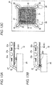
- Figs. 13A to 13C are views for describing a structure of the vicinity of the back plate 27 and the vibration electrode film 25.
- Fig. 13A is a sectional view illustrating a state before excessive pressure acts
- Fig. 13B is a sectional view illustrating a state where the excessive pressure has acted
- Fig. 13C is a plan view. Note that Figs. 13A and 13B are sectional views along an X-X cross section indicated in Fig. 13C .
- a wall 25d is provided in a portion, which faces a substrate 23, in the vibration electrode film 25 so as to surround a back chamber 22.
- the wall 25d of the vibration electrode film 25 abuts with the top surface of the substrate 23 to cut off a flow path for the air (inhibit the flow of the air) toward the back chamber 22, thereby enabling prevention of an increase in the pressure in the package.
- the wall 25d is provided so as to surround the opening of the back chamber 22 that is substantially square in a plan view, as indicated by a chain double-dashed line in Fig. 13C .
- the wall 25d is formed in a closed curve in a plan view in this case, the wall 25d may have a gap in a part thereof.
- a stopper (not illustrated) may be provided on the surface of the vibration electrode film 25 on the substrate 23 side in order to prevent occurrence of sticking between the vibration electrode film 25 and the substrate 23.
- a vibration electrode film 35 is disposed in a back plate 37 on the ceiling surface side (i.e., on the pressure hole side) as illustrated in Figs. 13A to 13C and Fig. 14A
- a wall 37d may be provided so as to surround a region where a sound hole 37a is disposed in the back plate 37.
- a cylindrical projection may be provided in the back plate 37 so as to surround the sound hole 37a. Further, such a projection as to block the sound hole 37a may be provided in the vibration electrode film 35.
- the projection or the wall may be formed by adding a curved shape to the back plate or the vibration electrode film.
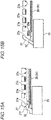
- FIG. 15A and 15B illustrates a sectional view of the vicinity of the back plate and the vibration electrode film in such a modified example.
- Fig. 15A is an example where a curved shape is added to the obliquely formed side surface of the back plate 27 to form a wall 27f.
- the end surface of the vibration part 31 comes close to the wall 27f, to cut off a flow path (inhibit the flow) at the time of the air flowing into the gap between the back plate 27 and the vibration electrode film 25 and prevent passage of the air through the sound hole 27a. It is thereby possible to prevent an increase in the pressure in the package.
- the end surface of the vibration part 31 comes close to the wall 27f, to cut off a flow path (inhibit the flow) at the time of the air flowing into the gap between the back plate 27 and the vibration electrode film 25.
- the surface of the vibration electrode film 25 on the back plate 27 side may abut with the wall 27f, to cut off the flow path (inhibit the flow) at the time of the air flowing into the gap between the back plate 27 and the vibration electrode film 25.
- Fig. 15B is an example where a projection 25e of the vibration electrode film 25 is formed by adding a curved shape to a part of the end of the vibration part 31 in the vibration electrode film 25. Also in this example, when excessive pressure acts on the acoustic sensor 1 and the vibration electrode film 25 is deformed to the back plate 27 side, the projection 25e blocks the sound hole 27a of the back plate 27, to cut off a flow path (inhibit the flow) at the time of the air flowing into the gap between the back plate 27 and the vibration electrode film 25 and prevent passage of the air through the sound hole 27a. It is thereby possible to prevent an increase in the pressure in the package.
- the present invention is also applicable to a case where the acoustic sensor 1 is used in an atmosphere other than the air. That is, the flow path cutoff part and the flow path inhibition part in the present invention may cut off a flow path for a fluid other than the air or inhibit the flow of the fluid.
- the vibration part of the vibration electrode film has been in a substantially square shape and the fixed parts have been formed on its periphery.
- the vibration part of the vibration electrode film may be in a circular shape as illustrated in Figs 16A and 16B or other shapes.
- one or more fixed parts 52 may be provided on the periphery of the circular vibration part 51 in a vibration electrode film 45 so as to radially extend as illustrated in Fig. 16A , or an outer peripheral portion of the circular vibration part 51 in the vibration electrode film 45 may directly function as the fixed part 52 that is fixed to the substrate 43 (or a back plate, not illustrated) as illustrated in Fig. 16B .
Landscapes
- Engineering & Computer Science (AREA)
- Physics & Mathematics (AREA)
- Acoustics & Sound (AREA)
- Signal Processing (AREA)
- Mechanical Engineering (AREA)
- Computer Hardware Design (AREA)
- Microelectronics & Electronic Packaging (AREA)
- Electrostatic, Electromagnetic, Magneto- Strictive, And Variable-Resistance Transducers (AREA)
- Pressure Sensors (AREA)
Claims (5)
- Capteur acoustique comprenant :un boîtier (106, 108) ayant un trou de pression (106a, 108b) qui permet l'entrée d'un fluide dans le boîtier (106, 108), dans lequel le boîtier abrite un transducteur capacitif MEMS qui comprend :un substrat semi-conducteur (23) ayant une ouverture (2) ;une plaque arrière (27) disposée de manière à faire face à l'ouverture (2) du substrat semi-conducteur (23), configurée pour fonctionner comme une électrode fixe, et ayant des trous sonores (27a) de forme circulaire qui permettent le passage de fluide ; etun film d'électrode à vibration (25) disposé de manière à faire face à la plaque arrière (27) à travers un vide,dans lequel le capteur acoustique est configuré de telle sorte quela déformation du film d'électrode à vibration (25) est convertie en un changement de capacité entre le film d'électrode à vibration (25) et la plaque arrière (27), etune partie de coupure du trajet d'écoulement est en outre prévue comme composant de la plaque arrière, la partie de coupure du trajet d'écoulement étant configurée pour couper au moins une partie d'un trajet d'écoulement pour un fluide qui passe à travers un espace entre le film d'électrode à vibration (25) et le substrat semi-conducteur (23) ou la plaque arrière (27) et/ou un trajet d'écoulement pour un fluide qui passe à travers l'ouverture (2) du substrat semi-conducteur (23) ou les trous sonores (27a) de la plaque arrière (27) lorsque le film d'électrode à vibration (25) est déformé pour se rapprocher du substrat semi-conducteur (23) ou de la plaque arrière (27),dans lequel la partie de coupure du trajet d'écoulement comprend plusieurs saillies (25c, 27c) prévues dans l'un du film d'électrode à vibration (25) et de la plaque arrière (27), et configurées pour bloquer certains des trous sonores (27a) dans la plaque arrière (27) en venant en butée avec l'autre du film d'électrode à vibration (25) et de la plaque arrière (27) lorsque le film d'électrode à vibration (25) est déformé pour se rapprocher de la plaque arrière (27),dans lequel chaque saillie (25c, 27c) des plusieurs saillies (25c, 27c) a une forme de tube cylindrique de manière à enfermer un trou respectif desdits certains trous sonores (27a) dans la plaque arrière (27) dans une vue en plan.
- Capteur acoustique selon la revendication 1, dans lequel les plusieurs saillies (25c, 27c) bloquent chacun des trous sonores (27a) sur toute la plaque arrière (27).
- Capteur acoustique selon la revendication 1 ou 2, dans lequelle film d'électrode à vibration (25) est formé en incluant une partie de vibration (31) en forme de plaque sur laquelle la pression agit, et une partie fixe (32) configurée pour fixer la partie de vibration (31) au substrat semi-conducteur (23) ou à la plaque arrière (27), etles plusieurs saillies (27c) bloquent le trou sonore (27a) disposé dans une partie dans la plaque arrière (27), la partie faisant face à une périphérie extérieure de la partie de vibration (31) du film d'électrode à vibration (25).
- Capteur acoustique selon l'une quelconque des revendications 1 à 3, dans lequel
la plaque arrière (27) est pourvue d'un film d'électrode fixe (8) uniquement dans une partie autre que celle faisant face aux extrémités des plusieurs saillies de la forme de tube cylindrique (25c, 27c) dans la plaque arrière (27). - Capteur acoustique selon l'une quelconque des revendications 1 à 4, dans lequelune butée (27b) est en outre prévue sur l'un du film d'électrode à vibration (25) et de la plaque arrière (27), la butée (27b) étant configurée pour venir en butée avec l'autre du film d'électrode à vibration (25) et de la plaque arrière (27) lorsque le film d'électrode à vibration (25) et la plaque arrière (27) viennent à proximité l'un de l'autre, etla partie de coupure du trajet d'écoulement est aussi haute ou plus haute que la butée (27b) dans une direction perpendiculaire à la plaque arrière et au film d'électrode à vibration.
Applications Claiming Priority (1)
| Application Number | Priority Date | Filing Date | Title |
|---|---|---|---|
| JP2016240655A JP6930101B2 (ja) | 2016-12-12 | 2016-12-12 | 音響センサ及び静電容量型トランスデューサ |
Publications (2)
| Publication Number | Publication Date |
|---|---|
| EP3334184A1 EP3334184A1 (fr) | 2018-06-13 |
| EP3334184B1 true EP3334184B1 (fr) | 2021-10-13 |
Family
ID=60190685
Family Applications (1)
| Application Number | Title | Priority Date | Filing Date |
|---|---|---|---|
| EP17198739.9A Active EP3334184B1 (fr) | 2016-12-12 | 2017-10-27 | Capteur acoustique et transducteur capacitif |
Country Status (4)
| Country | Link |
|---|---|
| US (1) | US10555087B2 (fr) |
| EP (1) | EP3334184B1 (fr) |
| JP (1) | JP6930101B2 (fr) |
| CN (1) | CN108235202B (fr) |
Families Citing this family (6)
| Publication number | Priority date | Publication date | Assignee | Title |
|---|---|---|---|---|
| US10962427B2 (en) * | 2019-01-10 | 2021-03-30 | Nextinput, Inc. | Slotted MEMS force sensor |
| CN115398183A (zh) * | 2020-01-17 | 2022-11-25 | 大不列颠哥伦比亚大学 | 柔性电容式微加工超声换能器阵列 |
| TWI770543B (zh) * | 2020-06-29 | 2022-07-11 | 美律實業股份有限公司 | 麥克風結構 |
| TWI786895B (zh) * | 2021-10-20 | 2022-12-11 | 大陸商美律電子(深圳)有限公司 | 電子裝置 |
| CN217363312U (zh) * | 2022-04-25 | 2022-09-02 | 瑞声声学科技(深圳)有限公司 | Mems麦克风 |
| JP7627707B1 (ja) * | 2022-08-25 | 2025-02-14 | エーエーシーアコースティックテクノロジーズ(シンセン)カンパニーリミテッド | マイクロフォンチップ及びマイクロフォン |
Family Cites Families (19)
| Publication number | Priority date | Publication date | Assignee | Title |
|---|---|---|---|---|
| HU183590B (en) * | 1981-09-28 | 1984-05-28 | Richter Gedeon Vegyeszet | Process for the isolation of an active suastance influencing specifically the nutrition centre with a regulative effect on the appetite from human and/or animal blood serum |
| KR100571967B1 (ko) * | 2000-08-11 | 2006-04-18 | 노우레스 일렉트로닉스, 엘엘시 | 소형 광대역 변환기 |
| US6535460B2 (en) * | 2000-08-11 | 2003-03-18 | Knowles Electronics, Llc | Miniature broadband acoustic transducer |
| DE102006001493B4 (de) * | 2006-01-11 | 2007-10-18 | Austriamicrosystems Ag | MEMS-Sensor und Verfahren zur Herstellung |
| TW200746868A (en) * | 2006-02-24 | 2007-12-16 | Yamaha Corp | Condenser microphone |
| US20080019543A1 (en) * | 2006-07-19 | 2008-01-24 | Yamaha Corporation | Silicon microphone and manufacturing method therefor |
| US7804969B2 (en) | 2006-08-07 | 2010-09-28 | Shandong Gettop Acoustic Co., Ltd. | Silicon microphone with impact proof structure |
| JP5402823B2 (ja) * | 2010-05-13 | 2014-01-29 | オムロン株式会社 | 音響センサ |
| JP5400708B2 (ja) | 2010-05-27 | 2014-01-29 | オムロン株式会社 | 音響センサ、音響トランスデューサ、該音響トランスデューサを利用したマイクロフォン、および音響トランスデューサの製造方法 |
| GB2506171B (en) | 2012-09-24 | 2015-01-28 | Wolfson Microelectronics Plc | MEMS device and process |
| KR20140040997A (ko) * | 2012-09-27 | 2014-04-04 | 한국전자통신연구원 | 멤스 마이크로폰 및 그 제조방법 |
| DE102012220006A1 (de) * | 2012-11-02 | 2014-05-08 | Robert Bosch Gmbh | Bauelement mit einer mikromechanischen Mikrofonstruktur |
| DE102013207497A1 (de) * | 2013-04-25 | 2014-11-13 | Robert Bosch Gmbh | Bauelement mit einer mikromechanischen Mikrofonstruktur |
| US9024396B2 (en) * | 2013-07-12 | 2015-05-05 | Infineon Technologies Ag | Device with MEMS structure and ventilation path in support structure |
| JP6179297B2 (ja) * | 2013-09-13 | 2017-08-16 | オムロン株式会社 | 音響トランスデューサ及びマイクロフォン |
| JP6311375B2 (ja) | 2014-03-14 | 2018-04-18 | オムロン株式会社 | 静電容量型トランスデューサ |
| US20160037263A1 (en) * | 2014-08-04 | 2016-02-04 | Knowles Electronics, Llc | Electrostatic microphone with reduced acoustic noise |
| WO2016029378A1 (fr) * | 2014-08-27 | 2016-03-03 | Goertek. Inc | Dispositif mems pourvu d'un mécanisme de soupape |
| US10375482B2 (en) * | 2015-03-12 | 2019-08-06 | Omron Corporation | Capacitance type transducer and acoustic sensor |
-
2016
- 2016-12-12 JP JP2016240655A patent/JP6930101B2/ja active Active
-
2017
- 2017-10-18 CN CN201710998297.9A patent/CN108235202B/zh active Active
- 2017-10-27 EP EP17198739.9A patent/EP3334184B1/fr active Active
- 2017-11-09 US US15/808,712 patent/US10555087B2/en active Active
Non-Patent Citations (1)
| Title |
|---|
| None * |
Also Published As
| Publication number | Publication date |
|---|---|
| JP2018098615A (ja) | 2018-06-21 |
| US20180167740A1 (en) | 2018-06-14 |
| EP3334184A1 (fr) | 2018-06-13 |
| CN108235202B (zh) | 2020-06-23 |
| CN108235202A (zh) | 2018-06-29 |
| US10555087B2 (en) | 2020-02-04 |
| JP6930101B2 (ja) | 2021-09-01 |
Similar Documents
| Publication | Publication Date | Title |
|---|---|---|
| EP3334184B1 (fr) | Capteur acoustique et transducteur capacitif | |
| CN104469640B (zh) | 声响转换器及麦克风 | |
| JP6445158B2 (ja) | バルブ機構付きのmemsデバイス | |
| CN104469578B (zh) | 声响转换器及麦克风 | |
| CN102771143B (zh) | 声音传感器与麦克风 | |
| CN106688246B (zh) | 静电电容式转换器及音响传感器 | |
| KR101566112B1 (ko) | Mems 구조체를 갖는 장치 및 지지 구조체의 통풍 경로 | |
| US9462389B2 (en) | Anti-impact silicon based MEMS microphone, a system and a package with the same | |
| KR20140000173A (ko) | 조절 가능한 통기 개구부를 갖는 mems 구조물 | |
| US10425743B2 (en) | Capacitive transducer and acoustic sensor | |
| US10469957B2 (en) | Capacitive transducer and acoustic sensor | |
| CN100473960C (zh) | 振动传感器 | |
| JP7219525B2 (ja) | トランスデューサ装置 | |
| JP2009060259A (ja) | 容量型センサ |
Legal Events
| Date | Code | Title | Description |
|---|---|---|---|
| PUAI | Public reference made under article 153(3) epc to a published international application that has entered the european phase |
Free format text: ORIGINAL CODE: 0009012 |
|
| STAA | Information on the status of an ep patent application or granted ep patent |
Free format text: STATUS: REQUEST FOR EXAMINATION WAS MADE |
|
| 17P | Request for examination filed |
Effective date: 20171027 |
|
| AK | Designated contracting states |
Kind code of ref document: A1 Designated state(s): AL AT BE BG CH CY CZ DE DK EE ES FI FR GB GR HR HU IE IS IT LI LT LU LV MC MK MT NL NO PL PT RO RS SE SI SK SM TR |
|
| AX | Request for extension of the european patent |
Extension state: BA ME |
|
| STAA | Information on the status of an ep patent application or granted ep patent |
Free format text: STATUS: EXAMINATION IS IN PROGRESS |
|
| 17Q | First examination report despatched |
Effective date: 20191111 |
|
| GRAP | Despatch of communication of intention to grant a patent |
Free format text: ORIGINAL CODE: EPIDOSNIGR1 |
|
| STAA | Information on the status of an ep patent application or granted ep patent |
Free format text: STATUS: GRANT OF PATENT IS INTENDED |
|
| INTG | Intention to grant announced |
Effective date: 20210511 |
|
| GRAS | Grant fee paid |
Free format text: ORIGINAL CODE: EPIDOSNIGR3 |
|
| GRAA | (expected) grant |
Free format text: ORIGINAL CODE: 0009210 |
|
| STAA | Information on the status of an ep patent application or granted ep patent |
Free format text: STATUS: THE PATENT HAS BEEN GRANTED |
|
| AK | Designated contracting states |
Kind code of ref document: B1 Designated state(s): AL AT BE BG CH CY CZ DE DK EE ES FI FR GB GR HR HU IE IS IT LI LT LU LV MC MK MT NL NO PL PT RO RS SE SI SK SM TR |
|
| REG | Reference to a national code |
Ref country code: GB Ref legal event code: FG4D |
|
| REG | Reference to a national code |
Ref country code: CH Ref legal event code: EP |
|
| REG | Reference to a national code |
Ref country code: DE Ref legal event code: R096 Ref document number: 602017047476 Country of ref document: DE |
|
| REG | Reference to a national code |
Ref country code: IE Ref legal event code: FG4D |
|
| REG | Reference to a national code |
Ref country code: AT Ref legal event code: REF Ref document number: 1439042 Country of ref document: AT Kind code of ref document: T Effective date: 20211115 |
|
| REG | Reference to a national code |
Ref country code: LT Ref legal event code: MG9D |
|
| REG | Reference to a national code |
Ref country code: NL Ref legal event code: MP Effective date: 20211013 |
|
| REG | Reference to a national code |
Ref country code: AT Ref legal event code: MK05 Ref document number: 1439042 Country of ref document: AT Kind code of ref document: T Effective date: 20211013 |
|
| REG | Reference to a national code |
Ref country code: DE Ref legal event code: R081 Ref document number: 602017047476 Country of ref document: DE Owner name: MMI SEMICONDUCTOR CO., LTD., TAMA-SHI, JP Free format text: FORMER OWNER: OMRON CORPORATION, KYOTO, JP |
|
| PG25 | Lapsed in a contracting state [announced via postgrant information from national office to epo] |
Ref country code: RS Free format text: LAPSE BECAUSE OF FAILURE TO SUBMIT A TRANSLATION OF THE DESCRIPTION OR TO PAY THE FEE WITHIN THE PRESCRIBED TIME-LIMIT Effective date: 20211013 Ref country code: LT Free format text: LAPSE BECAUSE OF FAILURE TO SUBMIT A TRANSLATION OF THE DESCRIPTION OR TO PAY THE FEE WITHIN THE PRESCRIBED TIME-LIMIT Effective date: 20211013 Ref country code: FI Free format text: LAPSE BECAUSE OF FAILURE TO SUBMIT A TRANSLATION OF THE DESCRIPTION OR TO PAY THE FEE WITHIN THE PRESCRIBED TIME-LIMIT Effective date: 20211013 Ref country code: BG Free format text: LAPSE BECAUSE OF FAILURE TO SUBMIT A TRANSLATION OF THE DESCRIPTION OR TO PAY THE FEE WITHIN THE PRESCRIBED TIME-LIMIT Effective date: 20220113 Ref country code: AT Free format text: LAPSE BECAUSE OF FAILURE TO SUBMIT A TRANSLATION OF THE DESCRIPTION OR TO PAY THE FEE WITHIN THE PRESCRIBED TIME-LIMIT Effective date: 20211013 |
|
| REG | Reference to a national code |
Ref country code: CH Ref legal event code: PL |
|
| PG25 | Lapsed in a contracting state [announced via postgrant information from national office to epo] |
Ref country code: IS Free format text: LAPSE BECAUSE OF FAILURE TO SUBMIT A TRANSLATION OF THE DESCRIPTION OR TO PAY THE FEE WITHIN THE PRESCRIBED TIME-LIMIT Effective date: 20220213 Ref country code: SE Free format text: LAPSE BECAUSE OF FAILURE TO SUBMIT A TRANSLATION OF THE DESCRIPTION OR TO PAY THE FEE WITHIN THE PRESCRIBED TIME-LIMIT Effective date: 20211013 Ref country code: PT Free format text: LAPSE BECAUSE OF FAILURE TO SUBMIT A TRANSLATION OF THE DESCRIPTION OR TO PAY THE FEE WITHIN THE PRESCRIBED TIME-LIMIT Effective date: 20220214 Ref country code: PL Free format text: LAPSE BECAUSE OF FAILURE TO SUBMIT A TRANSLATION OF THE DESCRIPTION OR TO PAY THE FEE WITHIN THE PRESCRIBED TIME-LIMIT Effective date: 20211013 Ref country code: NO Free format text: LAPSE BECAUSE OF FAILURE TO SUBMIT A TRANSLATION OF THE DESCRIPTION OR TO PAY THE FEE WITHIN THE PRESCRIBED TIME-LIMIT Effective date: 20220113 Ref country code: NL Free format text: LAPSE BECAUSE OF FAILURE TO SUBMIT A TRANSLATION OF THE DESCRIPTION OR TO PAY THE FEE WITHIN THE PRESCRIBED TIME-LIMIT Effective date: 20211013 Ref country code: LV Free format text: LAPSE BECAUSE OF FAILURE TO SUBMIT A TRANSLATION OF THE DESCRIPTION OR TO PAY THE FEE WITHIN THE PRESCRIBED TIME-LIMIT Effective date: 20211013 Ref country code: HR Free format text: LAPSE BECAUSE OF FAILURE TO SUBMIT A TRANSLATION OF THE DESCRIPTION OR TO PAY THE FEE WITHIN THE PRESCRIBED TIME-LIMIT Effective date: 20211013 Ref country code: GR Free format text: LAPSE BECAUSE OF FAILURE TO SUBMIT A TRANSLATION OF THE DESCRIPTION OR TO PAY THE FEE WITHIN THE PRESCRIBED TIME-LIMIT Effective date: 20220114 Ref country code: ES Free format text: LAPSE BECAUSE OF FAILURE TO SUBMIT A TRANSLATION OF THE DESCRIPTION OR TO PAY THE FEE WITHIN THE PRESCRIBED TIME-LIMIT Effective date: 20211013 |
|
| REG | Reference to a national code |
Ref country code: BE Ref legal event code: MM Effective date: 20211031 |
|
| REG | Reference to a national code |
Ref country code: DE Ref legal event code: R097 Ref document number: 602017047476 Country of ref document: DE |
|
| PG25 | Lapsed in a contracting state [announced via postgrant information from national office to epo] |
Ref country code: SM Free format text: LAPSE BECAUSE OF FAILURE TO SUBMIT A TRANSLATION OF THE DESCRIPTION OR TO PAY THE FEE WITHIN THE PRESCRIBED TIME-LIMIT Effective date: 20211013 Ref country code: SK Free format text: LAPSE BECAUSE OF FAILURE TO SUBMIT A TRANSLATION OF THE DESCRIPTION OR TO PAY THE FEE WITHIN THE PRESCRIBED TIME-LIMIT Effective date: 20211013 Ref country code: RO Free format text: LAPSE BECAUSE OF FAILURE TO SUBMIT A TRANSLATION OF THE DESCRIPTION OR TO PAY THE FEE WITHIN THE PRESCRIBED TIME-LIMIT Effective date: 20211013 Ref country code: MC Free format text: LAPSE BECAUSE OF FAILURE TO SUBMIT A TRANSLATION OF THE DESCRIPTION OR TO PAY THE FEE WITHIN THE PRESCRIBED TIME-LIMIT Effective date: 20211013 Ref country code: LU Free format text: LAPSE BECAUSE OF NON-PAYMENT OF DUE FEES Effective date: 20211027 Ref country code: EE Free format text: LAPSE BECAUSE OF FAILURE TO SUBMIT A TRANSLATION OF THE DESCRIPTION OR TO PAY THE FEE WITHIN THE PRESCRIBED TIME-LIMIT Effective date: 20211013 Ref country code: DK Free format text: LAPSE BECAUSE OF FAILURE TO SUBMIT A TRANSLATION OF THE DESCRIPTION OR TO PAY THE FEE WITHIN THE PRESCRIBED TIME-LIMIT Effective date: 20211013 Ref country code: CZ Free format text: LAPSE BECAUSE OF FAILURE TO SUBMIT A TRANSLATION OF THE DESCRIPTION OR TO PAY THE FEE WITHIN THE PRESCRIBED TIME-LIMIT Effective date: 20211013 Ref country code: BE Free format text: LAPSE BECAUSE OF NON-PAYMENT OF DUE FEES Effective date: 20211031 |
|
| PLBE | No opposition filed within time limit |
Free format text: ORIGINAL CODE: 0009261 |
|
| STAA | Information on the status of an ep patent application or granted ep patent |
Free format text: STATUS: NO OPPOSITION FILED WITHIN TIME LIMIT |
|
| PG25 | Lapsed in a contracting state [announced via postgrant information from national office to epo] |
Ref country code: LI Free format text: LAPSE BECAUSE OF NON-PAYMENT OF DUE FEES Effective date: 20211031 Ref country code: CH Free format text: LAPSE BECAUSE OF NON-PAYMENT OF DUE FEES Effective date: 20211031 |
|
| 26N | No opposition filed |
Effective date: 20220714 |
|
| GBPC | Gb: european patent ceased through non-payment of renewal fee |
Effective date: 20220113 |
|
| PG25 | Lapsed in a contracting state [announced via postgrant information from national office to epo] |
Ref country code: IE Free format text: LAPSE BECAUSE OF NON-PAYMENT OF DUE FEES Effective date: 20211027 Ref country code: GB Free format text: LAPSE BECAUSE OF NON-PAYMENT OF DUE FEES Effective date: 20220113 Ref country code: AL Free format text: LAPSE BECAUSE OF FAILURE TO SUBMIT A TRANSLATION OF THE DESCRIPTION OR TO PAY THE FEE WITHIN THE PRESCRIBED TIME-LIMIT Effective date: 20211013 |
|
| PG25 | Lapsed in a contracting state [announced via postgrant information from national office to epo] |
Ref country code: SI Free format text: LAPSE BECAUSE OF FAILURE TO SUBMIT A TRANSLATION OF THE DESCRIPTION OR TO PAY THE FEE WITHIN THE PRESCRIBED TIME-LIMIT Effective date: 20211013 Ref country code: FR Free format text: LAPSE BECAUSE OF NON-PAYMENT OF DUE FEES Effective date: 20211213 |
|
| PG25 | Lapsed in a contracting state [announced via postgrant information from national office to epo] |
Ref country code: IT Free format text: LAPSE BECAUSE OF FAILURE TO SUBMIT A TRANSLATION OF THE DESCRIPTION OR TO PAY THE FEE WITHIN THE PRESCRIBED TIME-LIMIT Effective date: 20211013 Ref country code: HU Free format text: LAPSE BECAUSE OF FAILURE TO SUBMIT A TRANSLATION OF THE DESCRIPTION OR TO PAY THE FEE WITHIN THE PRESCRIBED TIME-LIMIT; INVALID AB INITIO Effective date: 20171027 |
|
| PG25 | Lapsed in a contracting state [announced via postgrant information from national office to epo] |
Ref country code: CY Free format text: LAPSE BECAUSE OF FAILURE TO SUBMIT A TRANSLATION OF THE DESCRIPTION OR TO PAY THE FEE WITHIN THE PRESCRIBED TIME-LIMIT Effective date: 20211013 |
|
| PG25 | Lapsed in a contracting state [announced via postgrant information from national office to epo] |
Ref country code: MK Free format text: LAPSE BECAUSE OF FAILURE TO SUBMIT A TRANSLATION OF THE DESCRIPTION OR TO PAY THE FEE WITHIN THE PRESCRIBED TIME-LIMIT Effective date: 20211013 |
|
| PG25 | Lapsed in a contracting state [announced via postgrant information from national office to epo] |
Ref country code: MT Free format text: LAPSE BECAUSE OF FAILURE TO SUBMIT A TRANSLATION OF THE DESCRIPTION OR TO PAY THE FEE WITHIN THE PRESCRIBED TIME-LIMIT Effective date: 20211013 |
|
| PGFP | Annual fee paid to national office [announced via postgrant information from national office to epo] |
Ref country code: DE Payment date: 20241021 Year of fee payment: 8 |
|
| PG25 | Lapsed in a contracting state [announced via postgrant information from national office to epo] |
Ref country code: TR Free format text: LAPSE BECAUSE OF FAILURE TO SUBMIT A TRANSLATION OF THE DESCRIPTION OR TO PAY THE FEE WITHIN THE PRESCRIBED TIME-LIMIT Effective date: 20211013 |