EP3334228B1 - Procédé et dispositif d'attribution de ressources - Google Patents
Procédé et dispositif d'attribution de ressources Download PDFInfo
- Publication number
- EP3334228B1 EP3334228B1 EP15902569.1A EP15902569A EP3334228B1 EP 3334228 B1 EP3334228 B1 EP 3334228B1 EP 15902569 A EP15902569 A EP 15902569A EP 3334228 B1 EP3334228 B1 EP 3334228B1
- Authority
- EP
- European Patent Office
- Prior art keywords
- component carrier
- resource allocation
- carrier
- mapping relationship
- rbg
- Prior art date
- Legal status (The legal status is an assumption and is not a legal conclusion. Google has not performed a legal analysis and makes no representation as to the accuracy of the status listed.)
- Active
Links
Images







Classifications
-
- H—ELECTRICITY
- H04—ELECTRIC COMMUNICATION TECHNIQUE
- H04W—WIRELESS COMMUNICATION NETWORKS
- H04W72/00—Local resource management
- H04W72/20—Control channels or signalling for resource management
- H04W72/23—Control channels or signalling for resource management in the downlink direction of a wireless link, i.e. towards a terminal
-
- H—ELECTRICITY
- H04—ELECTRIC COMMUNICATION TECHNIQUE
- H04L—TRANSMISSION OF DIGITAL INFORMATION, e.g. TELEGRAPHIC COMMUNICATION
- H04L5/00—Arrangements affording multiple use of the transmission path
- H04L5/0091—Signalling for the administration of the divided path, e.g. signalling of configuration information
-
- H—ELECTRICITY
- H04—ELECTRIC COMMUNICATION TECHNIQUE
- H04L—TRANSMISSION OF DIGITAL INFORMATION, e.g. TELEGRAPHIC COMMUNICATION
- H04L5/00—Arrangements affording multiple use of the transmission path
- H04L5/0001—Arrangements for dividing the transmission path
- H04L5/0003—Two-dimensional division
- H04L5/0005—Time-frequency
- H04L5/0007—Time-frequency the frequencies being orthogonal, e.g. OFDM(A) or DMT
- H04L5/001—Time-frequency the frequencies being orthogonal, e.g. OFDM(A) or DMT the frequencies being arranged in component carriers
-
- H—ELECTRICITY
- H04—ELECTRIC COMMUNICATION TECHNIQUE
- H04L—TRANSMISSION OF DIGITAL INFORMATION, e.g. TELEGRAPHIC COMMUNICATION
- H04L5/00—Arrangements affording multiple use of the transmission path
- H04L5/003—Arrangements for allocating sub-channels of the transmission path
- H04L5/0053—Allocation of signalling, i.e. of overhead other than pilot signals
-
- H—ELECTRICITY
- H04—ELECTRIC COMMUNICATION TECHNIQUE
- H04W—WIRELESS COMMUNICATION NETWORKS
- H04W28/00—Network traffic management; Network resource management
- H04W28/16—Central resource management; Negotiation of resources or communication parameters, e.g. negotiating bandwidth or QoS [Quality of Service]
- H04W28/18—Negotiating wireless communication parameters
- H04W28/20—Negotiating bandwidth
-
- H—ELECTRICITY
- H04—ELECTRIC COMMUNICATION TECHNIQUE
- H04W—WIRELESS COMMUNICATION NETWORKS
- H04W72/00—Local resource management
- H04W72/04—Wireless resource allocation
-
- H—ELECTRICITY
- H04—ELECTRIC COMMUNICATION TECHNIQUE
- H04W—WIRELESS COMMUNICATION NETWORKS
- H04W72/00—Local resource management
- H04W72/04—Wireless resource allocation
- H04W72/044—Wireless resource allocation based on the type of the allocated resource
- H04W72/0453—Resources in frequency domain, e.g. a carrier in FDMA
-
- H—ELECTRICITY
- H04—ELECTRIC COMMUNICATION TECHNIQUE
- H04W—WIRELESS COMMUNICATION NETWORKS
- H04W72/00—Local resource management
- H04W72/12—Wireless traffic scheduling
- H04W72/1263—Mapping of traffic onto schedule, e.g. scheduled allocation or multiplexing of flows
-
- H—ELECTRICITY
- H04—ELECTRIC COMMUNICATION TECHNIQUE
- H04W—WIRELESS COMMUNICATION NETWORKS
- H04W88/00—Devices specially adapted for wireless communication networks, e.g. terminals, base stations or access point devices
- H04W88/12—Access point controller devices
Definitions
- Embodiments of the present invention relate to communications technologies, and in particular, to a resource allocation method and an apparatus.
- LTE Long Term Evolution
- six standard component carriers of 1.4 MHz, 3 MHz, 5 MHz, 10 MHz, 15 MHz, and 20 MHz in total are supported, and a quantity of resource blocks occupied by each standard component carrier is different from that of resource blocks occupied by another standard component carrier.
- a conventional terminal may transmit data by using a standard component carrier.
- an extension carrier technology is proposed.
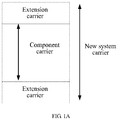
- FIG. 1A FIG. 1A is a schematic diagram of the new system carrier) that includes an extension carrier and a standard component carrier is introduced, and a new terminal that can support the new system carrier is correspondingly introduced.
- WO 2011/084822A1 refers to techniques for supporting communication with carrier extension.
- a base carrier and at least one segment available to a user equipment (UE) for communication may be determined.
- At least one operating parameter for the UE may be determined based on a composite bandwidth of the base carrier and the at least one segment.
- the UE may communicate based on the at least one operating parameter, which may include a resource block group (RBG) size and/or a bitmap used for resource allocation on the downlink, a gap used for resource allocation with frequency hopping on the downlink, a number of hopping bits used for resource allocation with frequency hopping on the uplink, a subband size and/or a number of bandwidth parts used for channel quality indicator (CQI) reporting, a sounding reference signal (SRS) bandwidth and/or a SRS configuration for SRS transmission on the uplink, and/or other operating parameters.
- RBG resource block group
- SRS sounding reference signal
- WO 2009/120827A1 refers to techniques for mapping virtual resources to physical resources in a wireless communication system.
- a virtual resource e.g., a virtual resource block
- a first mapping function which may map contiguous virtual resources to non-contiguous physical resources in the selected subset.
- the physical resource in the selected subset may then be mapped to an allocated physical resource (e.g., a physical resource block) among a plurality of available physical resources based on a second mapping function.
- the first mapping function may include (i) a re-mapping function that maps an index of the virtual resource to a temporary index and (ii) a permutation function (e.g., a bit-reversed row-column interleaver) that maps the temporary index to an index of the physical resource in the selected subset.
- a permutation function e.g., a bit-reversed row-column interleaver
- Embodiments of the present invention provide a resource allocation method and an apparatus, so that a resource allocation method applied to a new system carrier is implemented, and the new system carrier is accordingly compatible with a conventional terminal.
- a resource allocation method performed by a base station comprising:
- the method before the determining the first PRB to be allocated to the terminal and the resource allocation type, the method further comprises: determining that the terminal is a terminal that supports the new system carrier.
- a resource allocation method performed by a terminal comprising:
- the method further comprises: sending terminal type information to the base station.
- a base station configured to perform any of the methods according to the first aspect or its implementation forms.
- a terminal configured to perform any of the methods according to the second aspect or its implementation forms.
- a non-transitory computer-readable medium comprising instructions that, when executed, cause an apparatus to implement the method according to any one of the above methods.
- the base station determines the resource allocation type and the first physical resource that is to be allocated to the terminal that supports the new system carrier; further determines, according to the resource allocation type and the mapping relationship between a resource block unit and a physical resource, the first resource block unit corresponding to the first physical resource; and then sends the resource allocation information that includes the resource allocation type and the indication information of the first resource block unit to the terminal, so that the resource allocation method applied to the new system carrier is implemented.
- the first mapping relationship is the mapping relationship obtained by mapping, according to the resource allocation type and the bandwidth of the first part of component carrier in the component carrier, the resource block unit occupied by the first part of component carrier to the physical resource occupied by the first part of component carrier. Therefore, it can be ensured that when a new terminal transmits data by using the new system carrier, a conventional terminal can also transmit data by using a standard component carrier, that is, the new system carrier is compatible with the conventional terminal, so that resource utilization can be improved.
- a base station in the embodiments of the present invention may be a device that communicates with a wireless terminal by using one or more sectors over an air interface in an access network.
- the base station may be configured to perform mutual conversion between a received over-the-air frame and an IP packet, and serve as a router between the wireless terminal and a remaining part of the access network.
- the remaining part of the access network may include an Internet Protocol (IP) network.
- IP Internet Protocol
- the base station may further coordinate attribute management of the air interface.
- the base station may be a base transceiver station (BTS, Base Transceiver Station) in GSM or CDMA, may be a NodeB (NodeB) in WCDMA, or may be an evolved NodeB in LTE. This is not limited in the embodiments of the present invention.
- a terminal in the embodiments of the present invention that may also be referred to as a user equipment may be a wireless terminal.
- the wireless terminal may be a device that provides a user with voice and/or data connectivity, a handheld device with a wireless connection function, or another processing device connected to a wireless modem.
- the wireless terminal may communicate with one or more core networks by using a radio access network (RAN).
- RAN radio access network
- the wireless terminal may be a mobile terminal, such as a mobile phone (also referred to as a "cellular" phone) and a computer with a mobile terminal, for example, may be a portable, pocket-sized, handheld, computer built-in, or in-vehicle mobile apparatus, which exchanges voice and/or data with the radio access network.
- the wireless terminal may be a device such as a personal communication service (PCS) phone, a cordless telephone set, a Session Initiation Protocol (SIP) phone, a wireless local loop (WLL) station, or a personal digital assistant (PDA).
- the wireless terminal may also be referred to as a system, a subscriber unit (Subscriber Unit), a subscriber station (Subscriber Station), a mobile station, a remote station, an access point, a remote terminal, an access terminal, a user terminal, a user agent, a user device, or user equipment.
- a conventional terminal is a terminal that supports only a standard component carrier, for example, a Release-8 terminal or a Release-9 terminal.
- a new terminal is a terminal that can support a new system carrier, for example, a Release-15 terminal or a Release-16 terminal.
- a standard component carrier (which is briefly referred to as a component carrier) in the embodiments of the present invention is a carrier corresponding to a standard system bandwidth, for example, may be component carriers corresponding to six standard system bandwidths (1.4 MHz, 3 MHz, 5 MHz, 10 MHz, 15 MHz, and 20 MHz) in an LTE technology.
- a new system carrier in the embodiments of the present invention is a system carrier that includes a component carrier and an extension carrier.
- the extension carrier is a carrier corresponding to a bandwidth other than a standard system bandwidth. If a bandwidth of the new system carrier is 8 MHz, and a bandwidth of the standard component carrier is 5 MHz, a carrier corresponding to a remaining bandwidth of 3 MHz is the extension carrier.
- orthogonal frequency division multiple access In a downlink in an existing LTE technology, orthogonal frequency division multiple access (OFDMA for short) is used to implement resource allocation in a frequency domain based on a resource block (RB for short). Each resource block includes 12 subcarriers.
- a resource allocation granularity is a virtual resource block (VRB for short).
- VRB virtual resource block
- PRB physical resource block
- standard component carriers corresponding to the six standard system bandwidths of 1.4 MHz, 3 MHz, 5 MHz, 10 MHz, 15 MHz, and 20 MHz in total are supported.
- Quantities of RBs separately included in the six standard system bandwidths are 6, 15, 25, 50, 75, and 100 (that is, a quantity of RBs occupied by the component carrier of 1.4 MHz is 6, a quantity of RBs included in the standard system bandwidth of 3 MHz is 15, a quantity of RBs included in the standard system bandwidth of 5 MHz is 25, a quantity of RBs included in the standard system bandwidth of 10 MHz is 50, a quantity of RBs included in the standard system bandwidth of 15 MHz is 75, and a quantity of RBs included in the standard system bandwidth of 20 MHz is 100).
- Three downlink resource allocation manners are defined in the existing LTE: a type (type) 0, a type 1, and a type 2. The following first briefly describes the three downlink resource allocation manners separately.
- a status of allocating resource block groups is indicated in a bitmap (Bitmap) manner, and an allocation granularity for the resource allocation type 0 is an RBG.
- the RBG is a set of consecutive localized VRBs or PRBs.
- An RBG size is denoted as P (that is, a quantity of VRBs or PRBs included in each RBG) (a value of P may be 1, 2, 3, or 4).
- P is related to a system bandwidth, and a correspondence is shown in Table 1 (Table 1 is a table of a relationship between an RBG and a system bandwidth).
- N RB DL is a quantity of RBs included in a downlink system bandwidth.
- a mapping relationship between a VRB and an RBG may also be considered as a mapping relationship between a PRB and an RBG.
- Table 1 Table of a relationship between an RBG and a system bandwidth System bandwidth N RB DL RBG size (P) ⁇ 10 1 11 - 26 2 27 - 63 3 64 - 110 4
- a bitmap includes ⁇ N RB DL / P ⁇ bits in total, and each bit is corresponding to one RBG.
- these bitmap indication bits are notified to a terminal by using a resource block assignment (Resource block assignment) field in downlink control information (DCI for short) sent by a base station.
- DCI downlink control information
- Resource allocation type 1 is RBG-based non-contiguous VRB assignment.
- a resource block assignment field in DCI requires ⁇ N RB DL / P ⁇ bits to indicate the resource allocation type 1.
- One bit in the DCI is used to indicate whether a base station uses the resource allocation type 0 or the resource allocation type 1.
- RBGs are divided into P RBG subsets. For example, when a system bandwidth is 5 MHz, the RBGs are divided, as shown in Table 2 (Table 2 is a table of RBG division). Table 2: Table of RBG division Subset 0 RBG 0 RBG 2 RBG 4 RBG 6 RBG 8 RBG 10 RBG 12 Subset 1 RBG 1 RBG 3 RBG 5 RBG 7 RBG 9 RBG 11
- ⁇ log 2 ( P ) ⁇ bits are used to indicate a selected RBG subset, one bit is used to indicate whether there is a shift of a resource in an RBG subset, and N RB DL / P ⁇ ⁇ log 2 P ⁇ ⁇ 1 bits are used as a bitmap to indicate whether an RB in a corresponding subset is invoked.
- Resource allocation type 2 is contiguous VRB assignment.
- a resource indication value (RIV for short) is used to indicate a start location of allocated VRBs and a length in terms of the contiguously allocated VRBs.
- RIV calculation manner in a protocol is as follows: where L CRBs indicates a length in terms of contiguously allocated resource blocks, RB START is corresponding to a location of an allocated start resource block, and N RB DL is a quantity of RBs included in a downlink system bandwidth.
- a virtual resource block For the resource allocation type 2, a virtual resource block (VRB) needs to be mapped to a physical resource block (PRB), and a mapping manner is categorized into a localized VRB (LVRB for short) mapping manner and a distributed VRB (DVRB for short) mapping manner.
- LVRB localized VRB
- DVRB distributed VRB
- One bit in a downlink type 2 resource allocation indication is used to indicate whether an LVRB or a DVRB is used.
- n VRB is a number of a virtual resource block
- n PRB is a number of a physical resource block.
- the distributed VRB mapping manner is as follows: Each VRB is mapped to a PRB by using an interleaver.
- a quantity N VRB DL of VRBs that participate in interleaving is related to a downlink system bandwidth N RB DL , a gap (Gap) value ( N gap ), and an RBG size P.
- the quantity N VRB DL of VRBs that participate in interleaving is less than or equal to a quantity N RB DL of PRBs included in the system bandwidth.
- a same VRB is mapped to different PRBs in two different timeslots of a same subframe. There is a value of a gap between the two different PRBs.
- the gap value is determined according to Table 3 (Table 3 is a table of an RB gap value).
- Table 3 Table of an RB gap value System bandwidth N RB DL Gap ( N gap ) 1 st gap ( N gap,1 ) 2 nd gap ( N gap,2 ) 6 - 10 ⁇ N RB DL / 2 ⁇ N/A 11 4 N/A 12 - 19 8 N/A 20 - 26 12 N/A 27 - 44 18 N/A 45 - 49 27 N/A 50 - 63 27 9 64 - 79 32 16 80 - 110 48 16
- N VRB DL N VRB
- N VRB DL N VRB
- gap 1 DL 2 ⁇ min N gap , N RB DL ⁇ N gap .
- N VRB DL N VRB
- gap 2 DL ⁇ N RB DL / 2 N gap ⁇ ⁇ 2 N gap .
- a system bandwidth of 8 MHz (40 RBs) is used as an example for description.
- the conventional terminal can access only a standard system bandwidth of 5 MHz (that is, a standard component carrier), and the new terminal that supports 8 MHz can access the entire system bandwidth of 8 MHz (that is, a component carrier and an extension carrier).
- an RBG size (P) is 3.
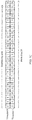
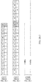
- an RBG size (P) is 2. If resources are directly allocated according to the resource allocation type 0, RBG division for the conventional terminal and that for the new terminal are shown in FIG. 1D-1 and FIG. 1D-2 (FIG.
- FIG. 1D-1 and FIG. 1D-2 are a schematic diagram 1 of the RBG division for the conventional terminal and that for the new terminal). As shown in FIG. 1D-1 and FIG. 1D-2 , an RBG division manner of PRBs occupied by the component carrier in the new system carrier supported by the new terminal is different from an RBG division manner of PRBs occupied by the standard component carrier supported by the conventional terminal. If an RBG 1 (corresponding to a PRB 3, a PRB 4, and a PRB 5) (indicated by a gray part in a second table in FIG.
- an RBG 1 (corresponding to a PRB 2 and a PRB 3) and an RBG 2 (corresponding to a PRB 4 and a PRB 5) (indicated by a gray part in a first table in FIG. 1D-1 ) that are corresponding to the conventional terminal cannot be allocated to the conventional terminal. If the RBG 1 or the RBG 2 that are corresponding to the conventional terminal are allocated to the conventional terminal, a resource allocation conflict is caused. It may be learned that the PRB 2 corresponding to the standard component carrier supported by the conventional terminal is not used. Consequently, a resource waste is caused. Similarly, a similar resource waste problem is also caused when resources in the new system carrier are directly allocated by using the resource allocation type 1.
- N gap N gap,1 18.
- N VRB DL 2 ⁇ min N gap
- N RB DL ⁇ N gap 36
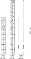
- the quantity of VRBs that participate in interleaving is 36. That is, distributed VRB mapping is performed on only 36 VRBs (which are numbered from 0 to 35), and VRBs whose numbers are 36 to 39 are directly mapped to PRBs whose numbers are 36 to 39 (that is, the VRBs 36 to 39 are mapped in the localized VRB mapping manner).
- a specific mapping result is shown in FIG. 1E-1 and FIG.
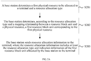
- FIG. 2A is a schematic flowchart of Embodiment 1 of a resource allocation method according to the present invention.
- the solution in this embodiment may be applied to a new system carrier.
- the new system carrier includes a component carrier and an extension carrier.
- the method in this embodiment may include the following steps.
- a resource allocation type 0 or a resource allocation type 1 may be used. If RBGs in remaining physical resources are insufficient to be allocated to the terminal, a resource allocation type 2 may be used.
- the resource allocation type includes, but is not limited to any one of the following types: the resource allocation type 0, the resource allocation type 1, and the resource allocation type 2.
- the first physical resource does not represent only one physical resource, and may represent at least one physical resource.
- the physical resource may be a PRB.
- the first physical resource may be a first PRB
- the mapping relationship between a resource block unit and a physical resource is the mapping relationship between a resource block unit and a PRB.
- the physical resource may alternatively be a physical resource in another form. This is not limited in this embodiment of the present invention.
- the resource block unit is a resource allocation granularity in which the base station allocates a resource to the terminal for the resource allocation type.
- the mapping relationship between a resource block unit and a physical resource may include a first mapping relationship and a second mapping relationship.
- the first mapping relationship is a mapping relationship obtained by mapping, according to the resource allocation type and a bandwidth of a first part of component carrier in the component carrier, a resource block unit occupied by the first part of component carrier to a physical resource occupied by the first part of component carrier.
- the remaining part of component carrier other than the first part of component carrier in the component carrier may be zero, that is, the first part of component carrier is the entire component carrier.
- the first mapping relationship is a mapping relationship obtained by mapping, according to the resource allocation type and a bandwidth of the component carrier, a resource block unit occupied by the component carrier to a physical resource occupied by the component carrier.
- the second mapping relationship is a mapping relationship obtained by mapping, according to the resource allocation type, a resource block unit occupied by the extension carrier to a physical resource occupied by the extension carrier.
- the physical resource may be a physical resource block PRB, and different resource allocation types may be corresponding to different mapping relationships between a resource block unit and a physical resource.
- the resource allocation type is the resource allocation type 0 or the resource allocation type 1
- the resource block unit is a resource block group RBG.
- the mapping relationship between a resource block unit and a physical resource is a mapping relationship between an RBG and a PRB.
- the resource allocation type is the resource allocation type 2
- the resource block unit is a virtual resource block VRB.
- the mapping relationship between a resource block unit and a physical resource is a mapping relationship between a VRB and a PRB.
- first resource block units corresponding to the first physical resource that are determined by the base station may also be different. For example, if the resource allocation type is the resource allocation type 0 or the resource allocation type 1, the resource block unit is a resource block group RBG and the first resource block unit is a first RBG. If the resource allocation type is the resource allocation type 2, the resource block unit is a virtual resource block VRB, and the first resource block unit is a first VRB.
- a mapping relationship that is between a resource block unit and a physical resource and that is corresponding to each resource allocation type may be preconfigured in the base station.
- the base station may determine a mapping relationship that is between a resource block unit and a physical resource and that is corresponding to each resource allocation type.
- the first mapping relationship is the mapping relationship obtained by mapping, according to the resource allocation type and the bandwidth of the first part of component carrier in the component carrier, the resource block unit occupied by the first part of component carrier to the physical resource occupied by the first part of component carrier. It may be learned that the mapping relationship between a resource block unit and a physical resource that are corresponding to the component carrier in the new system carrier is basically the same as a mapping relationship between a resource block unit and a physical resource that are corresponding to a standard component carrier. That is, a same resource block unit number is basically corresponding to a same physical resource number. Therefore, it can be ensured that when a new terminal transmits data by using the new system carrier, a conventional terminal can also transmit data by using the standard component carrier, that is, the new system carrier is compatible with the conventional terminal, so that resource utilization can be improved.
- the base station may send the DCI in different DCI formats to the terminal.
- the different DCI formats are used to indicate different resource allocation types (for example, a DCI format 1 is used to indicate the resource allocation type 0 or the resource allocation type 1, and a DCI format 1A is used to indicate the resource allocation type 2).
- the base station sends the resource allocation information to the terminal by using the DCI format 1.
- the DCI of format 1 includes a first field used to indicate the first resource block unit and a second field used to indicate the resource allocation type (for example, the resource allocation type 0 or the resource allocation type 1).
- the method further includes: determining, by the base station, that the terminal is a terminal that supports the new system carrier.
- the base station determines a type of the terminal by using terminal type information reported by the terminal.
- the terminal is a terminal that supports the new system carrier or a terminal that supports a standard component carrier.
- terminal types 0 to 10 are defined to indicate conventional terminals, and terminal types with type numbers greater than or equal to 11 are defined to indicate terminals that support the new system carrier.
- the resource allocation method applied to the new system carrier is implemented. It can be ensured that when the new terminal transmits data by using the new system carrier, the conventional terminal can also transmit data by using the standard component carrier, that is, the new system carrier is compatible with the conventional terminal, so that resource utilization can be improved.
- the physical resource may be a physical resource block PRB.
- the resource allocation type is the resource allocation type 0 or the resource allocation type 1
- the resource block unit is a resource block group RBG
- the first resource block unit is a first RBG.
- the mapping relationship between a resource block unit and a physical resource is a mapping relationship between an RBG and a PRB.
- the mapping relationship between an RBG and a PRB includes a first mapping relationship obtained by dividing, into at least one RBG according to a first division threshold, PRBs occupied by the first part of component carrier in the component carrier (a quantity of PRBs occupied by the first part of component carrier is an integer multiple of the first division threshold).
- the mapping relationship between an RBG and a PRB further includes a second mapping relationship obtained by dividing, into at least one RBG according to the first division threshold, PRBs occupied by the first extension carrier that includes the extension carrier and the remaining part of component carrier other than the first part of component carrier in the component carrier.
- the first division threshold is a quantity of PRBs included in each RBG of the component carrier. The first division threshold is determined according to the bandwidth of the component carrier and a relationship between an RBG and a system bandwidth. The relationship between an RBG and a system bandwidth includes the system bandwidth and an RBG size corresponding to the system bandwidth.
- the first division threshold (that is, an RBG size P) may be determined according to the bandwidth of the component carrier in the new system carrier and Table 1. If the bandwidth of the component carrier is 5 MHz, the first division threshold is 2. It may be understood that if a quantity of PRBs occupied by the component carrier is an integer multiple of the first division threshold, the first mapping relationship is a mapping relationship obtained by dividing, into at least one RBG according to the first division threshold, the PRBs occupied by the component carrier. In this case, the first part of component carrier is the entire component carrier.
- the second mapping relationship is a mapping relationship obtained by dividing, into at least one RBG according to the first division threshold, PRBs occupied by the extension carrier.
- FIG. 2B-1 and FIG. 2B-2 are a schematic diagram 2 of RBG division for the conventional terminal and that for the new terminal.
- the first mapping relationship (for example, a mapping relationship between a PRB 0 to a PRB 23 and an RBG 0 to an RBG 11 in the RBG division for the new terminal in FIG.
- the first mapping relationship and the second mapping relationship are included in the mapping relationship between an RBG and a PRB. It may be learned that the mapping relationship between an RBG and a PRB (for example, the mapping relationship between the PRB 0 to the PRB 23 and the RBG 0 to the RBG 11 in the RBG division for the new terminal in FIG. 2B-1 and FIG. 2B-2 ) that are corresponding to the first part of component carrier in the component carrier in the new system carrier is the same as the mapping relationship between an RBG and a PRB (for example, a mapping relationship between a PRB 0 to a PRB 23 and an RBG 0 to an RBG 11 in the RBG division for the conventional terminal in FIG. 2B-1 and FIG. 2B-2 ) that are corresponding to the standard component carrier.
- the mapping relationship between an RBG and a PRB for example, the mapping relationship between the PRB 0 to the PRB 23 and the RBG 0 to an RBG 11 in the RBG division for the conventional terminal in FIG. 2B-1 and FIG
- the base station determines, according to the resource allocation type and a mapping relationship between a resource block unit and a physical resource, a first resource block unit corresponding to the first physical resource includes the following steps: The base station determines, according to the resource allocation type (for example, the resource allocation type 0 or the resource allocation type 1), that the mapping relationship between a resource block unit and a PRB is the mapping relationship between an RBG and a PRB. Further, the base station determines, according to the mapping relationship between an RBG and a PRB, a first RBG corresponding to the first PRB, so as to send, to the terminal, the resource allocation information that includes indication information of the first RBG. If the first PRB is a PRB 18 in FIG.
- the resource allocation type for example, the resource allocation type 0 or the resource allocation type 1
- the base station determines, according to the mapping relationship between an RBG and a PRB, that a first RBG corresponding to the PRB 18 is an RBG 9. It may be learned that in this embodiment of the present invention, the resource allocation method applied to the new system carrier is implemented. It can be ensured that when the new terminal transmits data by using the new system carrier, the conventional terminal can also transmit data by using the standard component carrier, that is, the new system carrier is compatible with the conventional terminal, so that resource utilization can be improved.
- the first mapping relationship is a mapping relationship obtained by mapping, in a distributed VRB mapping manner to physical resources occupied by the component carrier, VRBs that are in VRBs occupied by the component carrier and that participate in interleaving, where the VRBs that participate in interleaving are VRBs occupied by the first part of component carrier; and the second mapping relationship is a mapping relationship obtained by mapping, in the distributed VRB mapping manner to a physical resource occupied by the extension carrier and a remaining physical resource in physical resources occupied by the component carrier, a VRB occupied by the extension carrier and a VRB that is in the VRBs occupied by the component carrier and that does not participate in interleaving, where the VRB that does not participate in interleaving and the VRB occupied by the extension carrier are VRBs occupied by the first extension carrier.
- the mapping relationship between a resource block unit and a physical resource is the mapping relationship between a VRB and a physical resource.
- the first mapping relationship and the second mapping relationship may be obtained in the foregoing manners. It may be understood that a quantity of VRBs that are in the VRBs occupied by the component carrier and that participate in interleaving may be equal to a quantity of VRBs occupied by the component carrier.
- the first mapping relationship is a mapping relationship obtained by mapping, in the distributed VRB mapping manner, the VRBs occupied by the component carrier to the physical resources occupied by the component carrier.
- the second mapping relationship is a mapping relationship obtained by mapping, in the distributed VRB mapping manner, the VRB occupied by the extension carrier to the physical resource occupied by the extension carrier.
- a mapping relationship between a VRB and a physical resource that are corresponding to the component carrier in the new system carrier is basically the same as a mapping relationship between a VRB and a physical resource that are corresponding to the standard component carrier. That is, a same VRB number is basically corresponding to a same physical resource number. Therefore, it can be ensured that when the new terminal transmits data by using the new system carrier, the conventional terminal can also transmit data by using the standard component carrier, that is, the new system carrier is compatible with the conventional terminal, so that resource utilization can be improved.
- the first mapping relationship is a mapping relationship obtained according to the following steps: determining the first RB gap (for example, a gap 1) according to the bandwidth of the component carrier in the new system carrier and Table 3 in the foregoing embodiment of the present invention, where the first RB gap is a value of a gap between PRBs to which a same VRB occupied by the component carrier is mapped in two different timeslots (a timeslot 0 and a timeslot 1) of a same subframe, for example, if a VRB 0 is mapped to a PRB 0 in the timeslot 0, the VRB 0 is mapped to a PRB (0 + gap 1) in the timeslot 1; further determining, according to the bandwidth of the component carrier and the first RB gap and according to the part about the "manner of determining the quantity N VRB DL of VRBs that participate in interleaving"
- the second mapping relationship is obtained in the following manner:
- the distributed VRB mapping is similar to an existing distributed VRB mapping process, and details are not described herein again.
- the base station determines, according to the mapping relationship between a VRB and a PRB, that a first VRB corresponding to the PRB 18 is a VRB 3 (in the timeslot 0). It may be learned that in this embodiment of the present invention, the resource allocation method applied to the new system carrier is implemented. Further, the mapping relationship between a VRB and a PRB that are corresponding to the component carrier in the new system carrier is basically the same as the mapping relationship between a VRB and a PRB that are corresponding to the standard component carrier, that is, a same VRB number is basically corresponding to a same PRB number. Therefore, it can be further ensured that when the new terminal transmits data by using the new system carrier, the conventional terminal can also transmit data by using the standard component carrier, that is, the new system carrier is compatible with the conventional terminal, so that resource utilization can be improved.
- FIG. 3 is a schematic flowchart of Embodiment 2 of a resource allocation method according to the present invention.
- the solution in this embodiment may be applied to a new system carrier.
- the new system carrier includes a component carrier (that is, a standard component carrier) and an extension carrier.
- a component carrier that is, a standard component carrier
- an extension carrier that is, a component carrier
- detailed descriptions are provided on a terminal side based on Embodiment 1 of the present invention.
- the method in this embodiment may include the following steps.
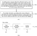
- a terminal receives resource allocation information sent by a base station, where the terminal supports a new system carrier, the new system carrier includes a component carrier and an extension carrier, and the resource allocation information includes a resource allocation type and indication information of a first resource block unit allocated by the base station to the terminal.
- the first physical resource may be a first PRB
- the mapping relationship between a resource block unit and a physical resource is the mapping relationship between a resource block unit and a PRB.
- the physical resource may alternatively be a physical resource in another form. This is not limited in this embodiment of the present invention.
- a mapping relationship that is between a resource block unit and a physical resource and that is corresponding to each resource allocation type may be preconfigured in the terminal.
- the terminal may determine a mapping relationship that is between a resource block unit and a physical resource and that is corresponding to each resource allocation type.
- the terminal obtains a first mapping relationship by mapping, according to the resource allocation type and a bandwidth of a first part of component carrier in the component carrier, a resource block unit occupied by the first part of component carrier to a physical resource occupied by the first part of component carrier, and the base station obtains a second mapping relationship by mapping, according to the resource allocation type, a resource block unit occupied by a first extension carrier to a physical resource occupied by the first extension carrier, where the first extension carrier includes the extension carrier and a remaining part of component carrier other than the first part of component carrier in the component carrier.
- the resource allocation information may be downlink control information DCI, may be carried in other control information, or may be a piece of independent/dedicated information.
- the terminal may alternatively receive, in another manner, the resource allocation information sent by the base station. This is not limited in this embodiment of the present invention.
- the terminal may receive DCI in different formats that is sent by the base station.
- the different DCI formats are used to indicate different resource allocation types (for example, a DCI format 1 is used to indicate the resource allocation type 0 or the resource allocation type 1, and a DCI format 1A is used to indicate the resource allocation type 2).
- the terminal may receive the DCI of format 1 sent by the base station.
- the DCI of format 1 includes a first field used to indicate the first resource block unit and a second field used to indicate the resource allocation type (for example, the resource allocation type 0 or the resource allocation type 1).
- the first field may be a resource block assignment field.
- the resource allocation information may further include mapping manner information of the localized VRB mapping or the distributed VRB mapping.
- the terminal may receive the DCI of format 1A sent by the base station.
- the DCI format 1A includes a first field used to indicate the first resource block unit and a second field used to indicate the mapping manner information (for example, localized VRB mapping or distributed VRB mapping).
- the first field may be a RIV field that is in the DCI of format 1A and that is used to indicate a segment of consecutive resources (that is, the first resource block unit).
- N RB DL in a RIV formula is a quantity of RBs occupied by the standard component carrier.
- N RB DL in a RIV formula is a sum of quantities of RBs occupied by the component carrier and the extension carrier in the new system carrier.
- the terminal determines, according to the resource allocation information and a mapping relationship between a resource block unit and a physical resource, a first physical resource corresponding to the first resource block unit allocated by the base station to the terminal.
- the mapping relationship between a resource block unit and a physical resource includes the first mapping relationship and the second mapping relationship.
- the first mapping relationship is a mapping relationship obtained by mapping, according to the resource allocation type and the bandwidth of the first part of component carrier in the component carrier, the resource block unit occupied by the first part of component carrier to the physical resource occupied by the first part of component carrier.
- the second mapping relationship is a mapping relationship obtained by mapping, according to the resource allocation type, the resource block unit occupied by the first extension carrier to the physical resource occupied by the first extension carrier, where the first extension carrier includes the extension carrier and the remaining part of component carrier other than the first part of component carrier in the component carrier.
- the remaining part of component carrier other than the first part of component carrier in the component carrier may be zero, that is, the first part of component carrier is the entire component carrier.
- the first mapping relationship is a mapping relationship obtained by mapping, according to the resource allocation type and a bandwidth of the component carrier, a resource block unit occupied by the component carrier to a physical resource occupied by the component carrier.
- the second mapping relationship is a mapping relationship obtained by mapping, according to the resource allocation type, a resource block unit occupied by the extension carrier to a physical resource occupied by the extension carrier.
- mapping relationship between a resource block unit and a physical resource the first mapping relationship, and the second mapping relationship, refer to related parts in the foregoing embodiment. Details are not described herein again.
- the terminal determines, according to the first resource block unit included in the resource allocation information and the mapping relationship that is between a resource block unit and a physical resource and that is corresponding to the resource allocation type, the first physical resource corresponding to the first resource block unit allocated by the base station to the terminal, so that the first physical resource can be used for data transmission between the base station and the terminal.
- the first mapping relationship is the mapping relationship obtained by mapping, according to the resource allocation type and the bandwidth of the first part of component carrier in the component carrier, the resource block unit occupied by the first part of component carrier to the physical resource occupied by the first part of component carrier. It may be learned that the mapping relationship between a resource block unit and a physical resource that are corresponding to the component carrier in the new system carrier is basically the same as a mapping relationship between a resource block unit and a physical resource that are corresponding to the standard component carrier. That is, a same resource block unit number is basically corresponding to a same physical resource number. Therefore, it can be ensured that when the new terminal transmits data by using the new system carrier, the conventional terminal can also transmit data by using the standard component carrier, that is, the new system carrier is compatible with the conventional terminal, so that resource utilization can be improved.
- the resource allocation method applied to the new system carrier is implemented. It can be ensured that when the new terminal transmits data by using the new system carrier, the conventional terminal can also transmit data by using the standard component carrier, that is, the new system carrier is compatible with the conventional terminal, so that resource utilization can be improved.
- the first physical resource is a first PRB
- the mapping relationship between a resource block unit and a physical resource is the mapping relationship between a resource block unit and a PRB.
- the terminal determines, according to the resource allocation information and a mapping relationship between a resource block unit and a physical resource, a first physical resource corresponding to the first resource block unit allocated by the base station to the terminal includes: the terminal determines the first PRB according to the indication information of the first resource block unit and a mapping relationship that is between a resource block unit and a PRB and that is corresponding to the resource allocation type.
- the terminal determines, according to the resource allocation type (for example, the resource allocation type 0 or the resource allocation type 1), that the mapping relationship between a resource block unit and a PRB is a mapping relationship between an RBG and a PRB (for example, a mapping relationship obtained after RBG division for the new terminal shown in FIG. 2B-1 and FIG. 2B-2 ), the terminal determines, according to the mapping relationship between an RBG and a PRB and the first RBG (for example, an RBG 9), the first PRB corresponding to the first RBG, so as to transmit data to the base station by using the first PRB.
- the resource allocation type for example, the resource allocation type 0 or the resource allocation type 1
- the resource allocation information further includes mapping manner information. That the terminal determines, according to the resource allocation information and a mapping relationship between a resource block unit and a physical resource, a first physical resource corresponding to the first resource block unit allocated by the base station to the terminal includes: the terminal determines the first PRB according to the indication information of the first resource block unit and a mapping relationship that is between a resource block unit and a PRB and that is corresponding to both the resource allocation type and the mapping manner information.
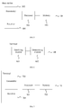
- the terminal determines, according to the resource allocation type (for example, the resource allocation type is the resource allocation type 2, and a mapping manner is distributed VRB mapping), that the mapping relationship between a resource block unit and a PRB is a mapping relationship between a VRB and a PRB (as shown in FIG. 2C-1 and FIG. 2C-2 ), the terminal determines, according to the mapping relationship between a VRB and a PRB and the first VRB (for example, a VRB 3), the first PRB (for example, a PRB 18) corresponding to the first VRB, so as to transmit data to the base station by using the first PRB.
- the resource allocation type for example, the resource allocation type is the resource allocation type 2, and a mapping manner is distributed VRB mapping
- the mapping relationship between a resource block unit and a PRB is a mapping relationship between a VRB and a PRB (as shown in FIG. 2C-1 and FIG. 2C-2 )
- the terminal determines, according to the mapping relationship between a VRB and
- FIG. 4 is a schematic structural diagram of a base station according to an embodiment of the present invention.
- a base station 40 provided in this embodiment can support a new system carrier.
- the new system carrier includes a component carrier and an extension carrier.
- the base station may include a first determining module 401, a second determining module 402, and a sending module 403.
- the first determining module 401 is configured to determine a first physical resource to be allocated to a terminal and a resource allocation type.
- the terminal supports a new system carrier, and the new system carrier includes a component carrier and an extension carrier.
- the second determining module 402 is configured to determine, according to the resource allocation type and a mapping relationship between a resource block unit and a physical resource, a first resource block unit corresponding to the first physical resource.
- the resource block unit is a resource allocation granularity in which the base station allocates a resource to the terminal.
- the mapping relationship between a resource block unit and a physical resource includes a first mapping relationship and a second mapping relationship.
- the first mapping relationship is a mapping relationship obtained by mapping, according to the resource allocation type and a bandwidth of a first part of component carrier in the component carrier, a resource block unit occupied by the first part of component carrier to a physical resource occupied by the first part of component carrier.
- the second mapping relationship is a mapping relationship obtained by mapping, according to the resource allocation type, a resource block unit occupied by a first extension carrier to a physical resource occupied by the first extension carrier, where the first extension carrier includes the extension carrier and a remaining part of component carrier other than the first part of component carrier in the component carrier.
- the sending module 403 is configured to send resource allocation information to the terminal.
- the resource allocation information includes the resource allocation type and indication information of the first resource block unit allocated by the base station to the terminal.
- the physical resource is a physical resource block PRB. If the resource allocation type is a resource allocation type 0 or a resource allocation type 1, the resource block unit is a resource block group RBG, and the first resource block unit is a first RBG.
- the resource allocation information further includes mapping manner information.
- the resource allocation information is downlink control information DCI.
- the base station further includes a storage module, and the storage module is configured to store the mapping relationship between a resource block unit and a physical resource.
- the base station further includes an identification module configured to determine that the terminal is a terminal that supports the new system carrier.
- FIG. 5 is a schematic structural diagram of a base station according to another embodiment of the present invention.
- the base station provided in this embodiment supports a new system carrier.
- the new system carrier includes a component carrier and an extension carrier.
- a base station 50 provided in this embodiment may include a processor 501 and a memory 502.
- the base station 50 may further include a transmitter 503 and a receiver 504.
- the transmitter 503 and the receiver 504 may be connected to the processor 501.
- the transmitter 503 is configured to send resource allocation information to a terminal.
- the resource allocation information includes a resource allocation type and indication information of a first resource block unit allocated by the base station to the terminal.
- the receiver 504 is configured to receive data or information.
- the memory 502 is configured to store a mapping relationship between a resource block unit and a physical resource and an execution instruction.
- the processor 501 communicates with the memory 502, and the processor 501 invokes the execution instruction in the memory 502 to perform the following operations:
- the physical resource is a physical resource block PRB. If the resource allocation type is a resource allocation type 0 or a resource allocation type 1, the resource block unit is a resource block group RBG, and the first resource block unit is a first RBG.
- the resource allocation information is downlink control information DCI.
- the processor is further configured to determine that the terminal is a terminal that supports the new system carrier.
- the physical resource may be a PRB.
- the base station in this embodiment may be configured to perform the technical solution in Embodiment 1 of the resource allocation method in the present invention. Implementation principles and technical effects thereof are similar to those of Embodiment 1, and are not described herein.
- FIG. 6 is a schematic structural diagram of a terminal according to an embodiment of the present invention.
- a terminal 60 provided in this embodiment can support a new system carrier.
- the new system carrier includes a component carrier and an extension carrier.
- the terminal 60 may include a receiving module 601 and a determining module 602.
- the receiving module 601 is configured to receive resource allocation information sent by a base station.
- the terminal supports the new system carrier.
- the new system carrier includes a component carrier and an extension carrier.
- the resource allocation information includes a resource allocation type and indication information of a first resource block unit allocated by the base station to the terminal.
- the determining module 602 is configured to determine, according to the resource allocation information and a mapping relationship between a resource block unit and a physical resource, a first physical resource corresponding to the first resource block unit allocated by the base station to the terminal.
- the mapping relationship between a resource block unit and a physical resource includes a first mapping relationship and a second mapping relationship.
- the first mapping relationship is a mapping relationship obtained by mapping, according to the resource allocation type and a bandwidth of a first part of component carrier in the component carrier, a resource block unit occupied by the first part of component carrier to a physical resource occupied by the first part of component carrier.
- the second mapping relationship is a mapping relationship obtained by mapping, according to the resource allocation type, a resource block unit occupied by a first extension carrier to a physical resource occupied by the first extension carrier, where the first extension carrier includes the extension carrier and a remaining part of component carrier other than the first part of component carrier in the component carrier.
- the physical resource is a physical resource block PRB; if the resource allocation type is a resource allocation type 0 or a resource allocation type 1, the resource block unit is a resource block group RBG, and the first resource block unit is a first RBG; and correspondingly, the determining module is specifically configured to determine the first physical resource according to the indication information of the first resource block unit and a mapping relationship that is between a resource block unit and a physical resource and that is corresponding to the resource allocation type; or if the resource allocation type is a resource allocation type 2, the resource block unit is a virtual resource block VRB, and the first resource block unit is a first VRB; correspondingly, the resource allocation information further includes mapping manner information; and the determining module is specifically configured to determine the first physical resource according to the indication information of the first resource block unit and a mapping relationship that is between a resource block unit and a physical resource and that is corresponding to both the resource allocation type and the mapping manner information.
- the resource allocation information is downlink control information DCI.
- the terminal further includes a storage module, and the storage module is configured to store the mapping relationship between a resource block unit and a physical resource.
- the terminal in this embodiment may be configured to perform the technical solution in Embodiment 2 of the resource allocation method in the present invention.
- Implementation principles and technical effects thereof are similar to those of Embodiment 2, and are not described herein.
- the resource allocation information includes a resource allocation type and indication information of a first resource block unit allocated by the base station to the terminal.
- the memory 702 stores a mapping relationship between a resource block unit and a physical resource and an execution instruction.
- the processor 701 communicates with the memory 702, and the processor 701 invokes the execution instruction in the memory 702 to perform the following operations: determining, according to the resource allocation information and the mapping relationship between a resource block unit and a physical resource, a first physical resource corresponding to the first resource block unit allocated by the base station to the terminal, where the mapping relationship between a resource block unit and a physical resource includes a first mapping relationship and a second mapping relationship, the first mapping relationship is a mapping relationship obtained by mapping, according to the resource allocation type and a bandwidth of a first part of component carrier in the component carrier, a resource block unit occupied by the first part of component carrier to a physical resource occupied by the first part of component carrier, and the second mapping relationship is a mapping relationship obtained by mapping, according to the resource allocation type, a
- the physical resource is a physical resource block PRB; if the resource allocation type is a resource allocation type 0 or a resource allocation type 1, the resource block unit is a resource block group RBG, and the first resource block unit is a first RBG; and correspondingly, the processor is specifically configured to determine the first PRB according to the indication information of the first resource block unit and a mapping relationship that is between a resource block unit and a PRB and that is corresponding to the resource allocation type; or if the resource allocation type is a resource allocation type 2, the resource block unit is a virtual resource block VRB, and the first resource block unit is a first VRB; correspondingly, the resource allocation information further includes mapping manner information; and the processor is specifically configured to determine the first PRB according to the indication information of the first resource block unit and a mapping relationship that is between a resource block unit and a PRB and that is corresponding to both the resource allocation type and the mapping manner information.
- the physical resource may be a PRB.
- the terminal in this embodiment may be configured to perform the technical solution in Embodiment 2 of the resource allocation method in the present invention.
- Implementation principles and technical effects thereof are similar to those of Embodiment 2, and are not described herein.
- resource allocation manners are described by using an example of the type 0, the type 1, and the type 2.
- the methods and apparatuses in the embodiments may be applied to resource allocation manners of various types.
- the program may be stored in a computer-readable storage medium. When the program runs, the steps of the method embodiments are performed.
- the foregoing storage medium includes any medium that can store program code, such as a ROM, a RAM, a magnetic disk, or an optical disc.
Landscapes
- Engineering & Computer Science (AREA)
- Signal Processing (AREA)
- Computer Networks & Wireless Communication (AREA)
- Quality & Reliability (AREA)
- Mobile Radio Communication Systems (AREA)
Claims (7)
- Procédé d'allocation de ressources exécuté par une station de base, le procédé comprenant :• la détermination d'un premier bloc de ressources physiques, PRB, devant être alloué à un terminal et d'un type d'allocation de ressources, dans lequel le terminal prend en charge une nouvelle porteuse système, et la nouvelle porteuse système comprend une porteuse composante et une porteuse extension, et le type d'allocation de ressources est soit un type d'allocation de ressources 0, soit un type d'allocation de ressources 1 (S201),• la détermination, en fonction du type d'allocation de ressources et d'une relation de correspondance entre un groupe de blocs de ressources, RBG, et un PRB, d'un premier RBG correspondant au premier PRB, dans lequel le RBG est une granularité d'allocation de ressources dans laquelle la station de base alloue une ressource au terminal, la relation de correspondance entre le RBG et le PRB comprend une première relation de correspondance et une seconde relation de correspondance, la première relation de correspondance est une relation de correspondance obtenue par la mise en correspondance, en fonction du type d'allocation de ressources et d'une largeur de bande d'une première partie de porteuse composante dans la porteuse composante, d'un RBG occupé par la première partie de porteuse composante, avec un PRB occupé par la première partie de porteuse composante, et la seconde relation de correspondance est une relation de correspondance obtenue par la mise en correspondance, en fonction du type d'allocation de ressources, d'un RBG occupé par une première porteuse extension, avec un PRB occupé par la première porteuse extension, dans lequel la première porteuse extension comprend la porteuse extension et une partie restante de porteuse composante autre que la première partie de porteuse composante dans la porteuse composante (S202),
dans lequel la première relation de correspondance est une relation de correspondance obtenue en divisant, en au moins un RBG en fonction d'un premier seuil de division, des PRB occupés par la première partie de porteuse composante dans la porteuse composante, dans lequel le premier seuil de division est déterminé en fonction d'une largeur de bande de la porteuse composante et d'une relation entre un RBG et une largeur de bande système, et une quantité de PRB occupés par la première partie de porteuse composante est un multiple entier du premier seuil de division, et
si une quantité de PRB occupés par la partie restante de porteuse composante autre que la première partie de porteuse composante dans la porteuse composante est inférieure au premier seuil de division, la seconde relation de correspondance est une relation de correspondance obtenue en divisant, en au moins un RBG en fonction d'un second seuil de division, des PRB occupés par la première porteuse extension qui comprend la porteuse extension et la partie restante de porteuse composante autre que la première partie de porteuse composante dans la porteuse composante,
dans lequel le second seuil de division est différent du premier seuil de division et est déterminé en fonction d'une largeur de bande de la première porteuse extension et de la relation entre le RBG et la largeur de bande système, et• l'envoi d'informations d'allocation de ressources au terminal, dans lequel les informations d'allocation de ressources comprennent le type d'allocation de ressources et des informations d'indication du premier RBG alloué par la station de base au terminal (S203). - Procédé selon la revendication 1, avant la détermination du premier PRB devant être alloué au terminal et du type d'allocation de ressources, le procédé comprenant en outre :
la détermination du fait que le terminal est un terminal qui prend en charge la nouvelle porteuse système. - Procédé d'allocation de ressources exécuté par un terminal, le procédé comprenant :• la réception d'informations d'allocation de ressources en provenance d'une station de base, dans lequel le terminal prend en charge une nouvelle porteuse système, la nouvelle porteuse système comprend une porteuse composante et une porteuse extension, et les informations d'allocation de ressources comprennent un type d'allocation de ressources et des informations d'indication d'un premier groupe de blocs de ressources, RBG, dans lequel le type d'allocation de ressources est soit un type d'allocation de ressources 0, soit un type d'allocation de ressources 1 (S301),• la détermination, en fonction des informations d'indication du premier RBG et d'une relation de correspondance entre un RBG et un bloc de ressources physiques, PRB, d'un premier PRB correspondant au type d'allocation de ressources, dans lequel la relation de correspondance entre le RBG et le PRB comprend une première relation de correspondance et une seconde relation de correspondance, la première relation de correspondance est une relation de correspondance obtenue par la mise en correspondance, en fonction du type d'allocation de ressources et d'une largeur de bande d'une première partie de porteuse composante dans la porteuse composante, d'un RBG occupé par la première partie de porteuse composante avec un PRB occupé par la première partie de porteuse composante, et la seconde relation de correspondance est une relation de correspondance obtenue par la mise en correspondance, en fonction du type d'allocation de ressources, d'un RBG occupé par une première porteuse extension avec un PRB occupé par la première porteuse extension, dans lequel la première porteuse extension comprend la porteuse extension et une partie restante de porteuse composante autre que la première partie de porteuse composante dans la porteuse composante (S302),
caractérisé en ce que
la première relation de correspondance est une relation de correspondance obtenue en divisant, en au moins un RBG en fonction d'un premier seuil de division, des PRB occupés par la première partie de porteuse composante dans la porteuse composante, dans lequel le premier seuil de division est déterminé en fonction d'une largeur de bande de la porteuse composante et d'une relation entre un RBG et une largeur de bande système, et une quantité de PRB occupés par la première partie de porteuse composante est un multiple entier du premier seuil de division, et
si une quantité de PRB occupés par la partie restante de porteuse composante autre que la première partie de porteuse composante dans la porteuse composante est inférieure au premier seuil de division, la seconde relation de correspondance est une relation de correspondance obtenue en divisant, en au moins un RBG en fonction d'un second seuil de division, des PRB occupés par la première porteuse extension qui comprend la porteuse extension et la partie restante de porteuse composante autre que la première partie de porteuse composante dans la porteuse composante, dans lequel le second seuil de division est différent du premier seuil de division et est déterminé en fonction d'une largeur de bande de la première porteuse extension et de la relation entre le RBG et la largeur de bande système. - Procédé selon la revendication 3, avant la réception d'informations d'allocation de ressources envoyées par la station de base, le procédé comprenant en outre :
l'envoi d'informations de type de terminal à la station de base. - Station de base configurée pour exécuter l'un quelconque des procédés selon les revendications 1 et 2.
- Terminal configuré pour exécuter l'un quelconque des procédés selon les revendications 3 et 4.
- Support non transitoire lisible par ordinateur, comprenant des instructions qui, lorsqu'elles sont exécutées, amènent un appareil à mettre en œuvre le procédé selon l'une quelconque des revendications 1 et 2 ou l'une quelconque des revendications 3 et 4.
Applications Claiming Priority (1)
| Application Number | Priority Date | Filing Date | Title |
|---|---|---|---|
| PCT/CN2015/088692 WO2017035762A1 (fr) | 2015-08-31 | 2015-08-31 | Procédé et dispositif d'attribution de ressources |
Publications (3)
| Publication Number | Publication Date |
|---|---|
| EP3334228A1 EP3334228A1 (fr) | 2018-06-13 |
| EP3334228A4 EP3334228A4 (fr) | 2018-08-01 |
| EP3334228B1 true EP3334228B1 (fr) | 2020-06-03 |
Family
ID=58186579
Family Applications (1)
| Application Number | Title | Priority Date | Filing Date |
|---|---|---|---|
| EP15902569.1A Active EP3334228B1 (fr) | 2015-08-31 | 2015-08-31 | Procédé et dispositif d'attribution de ressources |
Country Status (5)
| Country | Link |
|---|---|
| US (1) | US10484984B2 (fr) |
| EP (1) | EP3334228B1 (fr) |
| JP (1) | JP6595098B2 (fr) |
| CN (1) | CN107925999B (fr) |
| WO (1) | WO2017035762A1 (fr) |
Families Citing this family (18)
| Publication number | Priority date | Publication date | Assignee | Title |
|---|---|---|---|---|
| JP6528996B1 (ja) * | 2016-03-27 | 2019-06-12 | オフィノ, エルエルシー | 無線ネットワークにおけるチャネル状態情報伝送 |
| US10863505B2 (en) * | 2016-08-26 | 2020-12-08 | Qualcomm Incorporated | Data channel resource allocation |
| WO2018053160A1 (fr) * | 2016-09-15 | 2018-03-22 | Intel IP Corporation | Conception de canal de commande de liaison descendante pour des systèmes de formation de faisceau |
| EP3619995B1 (fr) | 2017-05-05 | 2022-11-16 | ZTE Corporation | Système et procédé d'attribution de blocs de ressources |
| KR101950995B1 (ko) * | 2017-06-08 | 2019-02-22 | 엘지전자 주식회사 | 무선 통신 시스템에서 자원 할당 관련 시그널링 방법 및 상기 방법을 이용하는 장치 |
| CN109391417B (zh) * | 2017-08-11 | 2022-05-13 | 华为技术有限公司 | 传输下行控制信息的方法、装置和系统 |
| CN109803412B (zh) * | 2017-11-17 | 2021-01-29 | 维沃移动通信有限公司 | 资源映射方法、确定方法、网络侧设备及用户终端 |
| CN109995467B (zh) * | 2018-01-03 | 2020-09-01 | 电信科学技术研究院 | 一种资源映射方法及装置、设备 |
| WO2019157674A1 (fr) * | 2018-02-13 | 2019-08-22 | 华为技术有限公司 | Procédé d'indication d'informations et équipement associé |
| EP3737180B1 (fr) | 2018-02-14 | 2025-04-23 | Huawei Technologies Co., Ltd. | Procédé et appareil pour l'attribution d'une ressource de domaine fréquentiel |
| WO2019157726A1 (fr) * | 2018-02-14 | 2019-08-22 | Oppo广东移动通信有限公司 | Procédé d'indication de ressources, dispositif terminal, et dispositif de réseau |
| US10776163B1 (en) * | 2018-03-16 | 2020-09-15 | Amazon Technologies, Inc. | Non-hierarchical management system for application programming interface resources |
| CN110831022B (zh) * | 2018-08-09 | 2023-05-26 | 北京三星通信技术研究有限公司 | 物理资源处理方法及用户设备 |
| CN112996112B (zh) * | 2019-12-12 | 2023-01-20 | 大唐移动通信设备有限公司 | 一种频域资源分配方法、装置、电子设备及存储介质 |
| CN111315023B (zh) * | 2020-02-19 | 2022-08-02 | 中国联合网络通信集团有限公司 | 一种上行无线资源分配方法及装置 |
| EP4233430A4 (fr) * | 2020-10-23 | 2024-08-14 | Qualcomm Incorporated | Système et procédé de mappage de signaux de référence de sondage à des ressources |
| CN112804757B (zh) * | 2020-12-30 | 2023-05-02 | 联想未来通信科技(重庆)有限公司 | 一种频域资源分配类型的切换方法、装置及可读存储介质 |
| CN117880985A (zh) * | 2022-09-30 | 2024-04-12 | 大唐移动通信设备有限公司 | 信息处理方法、配置方法、装置、终端及网络侧设备 |
Family Cites Families (12)
| Publication number | Priority date | Publication date | Assignee | Title |
|---|---|---|---|---|
| EP2106057A1 (fr) * | 2008-03-25 | 2009-09-30 | Panasonic Corporation | Signalisation de bloc de transport dépendant de la taille d'attribution de ressources |
| US8493835B2 (en) * | 2008-03-26 | 2013-07-23 | Qualcomm, Incorporated | Method and apparatus for mapping virtual resources to physical resources in a wireless communication system |
| CN101765208B (zh) * | 2008-12-26 | 2013-11-06 | 华为技术有限公司 | 资源分配的方法、网络设备和无线系统 |
| EP2512050B1 (fr) * | 2009-12-07 | 2018-10-03 | LG Electronics Inc. | Procédé et appareil permettant de transmettre et de recevoir un signal dans un système de communication sans fil qui supporte de multiples porteuses composantes |
| US9276710B2 (en) * | 2009-12-21 | 2016-03-01 | Qualcomm Incorporated | Method and apparatus for resource allocation with carrier extension |
| KR20110082899A (ko) * | 2010-01-12 | 2011-07-20 | 주식회사 팬택 | 데이터 전송 결과를 다중으로 송수신하는 방법 및 장치 |
| CN102340875B (zh) * | 2010-07-23 | 2014-03-26 | 华为技术有限公司 | 资源分配方法和装置 |
| ES2610909T3 (es) * | 2011-04-01 | 2017-05-04 | Intel Corporation | Soporte de segmento de portadora para redes inalámbricas |
| EP3668136B1 (fr) | 2011-04-18 | 2022-11-16 | Huawei Technologies Co., Ltd. | Procédé d'agencement de transmissions sur une porteuse en liaison descendante |
| CN102970753B (zh) * | 2011-09-01 | 2018-01-30 | 中兴通讯股份有限公司 | 一种rbg处理方法和系统 |
| WO2013067675A1 (fr) * | 2011-11-07 | 2013-05-16 | Renesas Mobile Corporation | Transmissions en liaison montante et autorisations dans une porteuse d'extension |
| CN103108394B (zh) * | 2011-11-15 | 2015-12-16 | 华为技术有限公司 | 一种扩展载波的资源配置方法、装置及系统 |
-
2015
- 2015-08-31 EP EP15902569.1A patent/EP3334228B1/fr active Active
- 2015-08-31 WO PCT/CN2015/088692 patent/WO2017035762A1/fr not_active Ceased
- 2015-08-31 JP JP2018510974A patent/JP6595098B2/ja active Active
- 2015-08-31 CN CN201580082666.9A patent/CN107925999B/zh active Active
-
2018
- 2018-02-27 US US15/906,994 patent/US10484984B2/en active Active
Non-Patent Citations (1)
| Title |
|---|
| None * |
Also Published As
| Publication number | Publication date |
|---|---|
| JP6595098B2 (ja) | 2019-10-23 |
| CN107925999B (zh) | 2020-12-01 |
| JP2018529288A (ja) | 2018-10-04 |
| US10484984B2 (en) | 2019-11-19 |
| EP3334228A1 (fr) | 2018-06-13 |
| EP3334228A4 (fr) | 2018-08-01 |
| US20180192406A1 (en) | 2018-07-05 |
| WO2017035762A1 (fr) | 2017-03-09 |
| CN107925999A (zh) | 2018-04-17 |
Similar Documents
| Publication | Publication Date | Title |
|---|---|---|
| US10484984B2 (en) | Resource allocation method and apparatus | |
| US11832089B2 (en) | Systems and methods for multicast resource allocation | |
| US11044147B2 (en) | Resource configuration method and apparatus | |
| JP5226864B2 (ja) | 電気通信ネットワークにおけるシグナリングリソース割当 | |
| US11395291B2 (en) | Allocating transmission resources in communication networks that provide low latency services | |
| EP3232613B1 (fr) | Procédé et dispositif de transmission de canal de commande de liaison descendante | |
| US20180049176A1 (en) | Methods for allocating data channel resources in a wireless communication system and apparatuses | |
| EP2757849B1 (fr) | Procédé et dispositif de planification multi-porteuses | |
| US20190261332A1 (en) | Control Information Detection Method, Control Information Sending Method, And Device | |
| US10869304B2 (en) | Downlink control information sending method, downlink control information detection method, and device | |
| CN103517429B (zh) | 数据传输方法及窄带终端、基站 | |
| CN101801093A (zh) | 资源分配方式指示方法、装置和系统 | |
| US20250193862A1 (en) | Downlink (dl) and uplink (ul) scheduling for transmission above 52.6 ghz | |
| CN109803422B (zh) | 一种资源激活的方法及相关设备 | |
| US10575308B2 (en) | Resource allocation method, base station, and user equipment | |
| US20250105960A1 (en) | Method for determining transport block size, and device | |
| CN117998610A (zh) | 用于通过单个dci的多小区调度的时域资源分配 | |
| US20240414700A1 (en) | Method and apparatus for frequency domain resource allocation for multicast downlink transmissions | |
| US11044745B2 (en) | Wireless communication method and device to reduce receiving performance loss from resource allocation | |
| CN109089317B (zh) | 参数配置方法、终端设备、网络侧设备和通信系统 | |
| US20250338266A1 (en) | Method for determining transport block size, and terminal device and network device thereof | |
| KR20180018987A (ko) | 무선 통신 시스템에서 데이터 채널 자원을 할당하는 방법 및 그 장치 | |
| WO2024168640A1 (fr) | Procédé et appareil de transmission, dispositif, support de stockage et produit |
Legal Events
| Date | Code | Title | Description |
|---|---|---|---|
| STAA | Information on the status of an ep patent application or granted ep patent |
Free format text: STATUS: THE INTERNATIONAL PUBLICATION HAS BEEN MADE |
|
| PUAI | Public reference made under article 153(3) epc to a published international application that has entered the european phase |
Free format text: ORIGINAL CODE: 0009012 |
|
| STAA | Information on the status of an ep patent application or granted ep patent |
Free format text: STATUS: REQUEST FOR EXAMINATION WAS MADE |
|
| 17P | Request for examination filed |
Effective date: 20180306 |
|
| AK | Designated contracting states |
Kind code of ref document: A1 Designated state(s): AL AT BE BG CH CY CZ DE DK EE ES FI FR GB GR HR HU IE IS IT LI LT LU LV MC MK MT NL NO PL PT RO RS SE SI SK SM TR |
|
| AX | Request for extension of the european patent |
Extension state: BA ME |
|
| A4 | Supplementary search report drawn up and despatched |
Effective date: 20180703 |
|
| RIC1 | Information provided on ipc code assigned before grant |
Ipc: H04W 72/04 20090101AFI20180627BHEP |
|
| DAV | Request for validation of the european patent (deleted) | ||
| DAX | Request for extension of the european patent (deleted) | ||
| GRAP | Despatch of communication of intention to grant a patent |
Free format text: ORIGINAL CODE: EPIDOSNIGR1 |
|
| STAA | Information on the status of an ep patent application or granted ep patent |
Free format text: STATUS: GRANT OF PATENT IS INTENDED |
|
| INTG | Intention to grant announced |
Effective date: 20200107 |
|
| GRAS | Grant fee paid |
Free format text: ORIGINAL CODE: EPIDOSNIGR3 |
|
| GRAA | (expected) grant |
Free format text: ORIGINAL CODE: 0009210 |
|
| STAA | Information on the status of an ep patent application or granted ep patent |
Free format text: STATUS: THE PATENT HAS BEEN GRANTED |
|
| AK | Designated contracting states |
Kind code of ref document: B1 Designated state(s): AL AT BE BG CH CY CZ DE DK EE ES FI FR GB GR HR HU IE IS IT LI LT LU LV MC MK MT NL NO PL PT RO RS SE SI SK SM TR |
|
| REG | Reference to a national code |
Ref country code: GB Ref legal event code: FG4D |
|
| REG | Reference to a national code |
Ref country code: CH Ref legal event code: EP Ref country code: AT Ref legal event code: REF Ref document number: 1278426 Country of ref document: AT Kind code of ref document: T Effective date: 20200615 |
|
| REG | Reference to a national code |
Ref country code: DE Ref legal event code: R096 Ref document number: 602015053961 Country of ref document: DE |
|
| REG | Reference to a national code |
Ref country code: LT Ref legal event code: MG4D |
|
| PG25 | Lapsed in a contracting state [announced via postgrant information from national office to epo] |
Ref country code: SE Free format text: LAPSE BECAUSE OF FAILURE TO SUBMIT A TRANSLATION OF THE DESCRIPTION OR TO PAY THE FEE WITHIN THE PRESCRIBED TIME-LIMIT Effective date: 20200603 Ref country code: LT Free format text: LAPSE BECAUSE OF FAILURE TO SUBMIT A TRANSLATION OF THE DESCRIPTION OR TO PAY THE FEE WITHIN THE PRESCRIBED TIME-LIMIT Effective date: 20200603 Ref country code: FI Free format text: LAPSE BECAUSE OF FAILURE TO SUBMIT A TRANSLATION OF THE DESCRIPTION OR TO PAY THE FEE WITHIN THE PRESCRIBED TIME-LIMIT Effective date: 20200603 Ref country code: NO Free format text: LAPSE BECAUSE OF FAILURE TO SUBMIT A TRANSLATION OF THE DESCRIPTION OR TO PAY THE FEE WITHIN THE PRESCRIBED TIME-LIMIT Effective date: 20200903 Ref country code: GR Free format text: LAPSE BECAUSE OF FAILURE TO SUBMIT A TRANSLATION OF THE DESCRIPTION OR TO PAY THE FEE WITHIN THE PRESCRIBED TIME-LIMIT Effective date: 20200904 |
|
| REG | Reference to a national code |
Ref country code: NL Ref legal event code: MP Effective date: 20200603 |
|
| PG25 | Lapsed in a contracting state [announced via postgrant information from national office to epo] |
Ref country code: RS Free format text: LAPSE BECAUSE OF FAILURE TO SUBMIT A TRANSLATION OF THE DESCRIPTION OR TO PAY THE FEE WITHIN THE PRESCRIBED TIME-LIMIT Effective date: 20200603 Ref country code: BG Free format text: LAPSE BECAUSE OF FAILURE TO SUBMIT A TRANSLATION OF THE DESCRIPTION OR TO PAY THE FEE WITHIN THE PRESCRIBED TIME-LIMIT Effective date: 20200903 Ref country code: HR Free format text: LAPSE BECAUSE OF FAILURE TO SUBMIT A TRANSLATION OF THE DESCRIPTION OR TO PAY THE FEE WITHIN THE PRESCRIBED TIME-LIMIT Effective date: 20200603 Ref country code: LV Free format text: LAPSE BECAUSE OF FAILURE TO SUBMIT A TRANSLATION OF THE DESCRIPTION OR TO PAY THE FEE WITHIN THE PRESCRIBED TIME-LIMIT Effective date: 20200603 |
|
| REG | Reference to a national code |
Ref country code: AT Ref legal event code: MK05 Ref document number: 1278426 Country of ref document: AT Kind code of ref document: T Effective date: 20200603 |
|
| PG25 | Lapsed in a contracting state [announced via postgrant information from national office to epo] |
Ref country code: NL Free format text: LAPSE BECAUSE OF FAILURE TO SUBMIT A TRANSLATION OF THE DESCRIPTION OR TO PAY THE FEE WITHIN THE PRESCRIBED TIME-LIMIT Effective date: 20200603 Ref country code: AL Free format text: LAPSE BECAUSE OF FAILURE TO SUBMIT A TRANSLATION OF THE DESCRIPTION OR TO PAY THE FEE WITHIN THE PRESCRIBED TIME-LIMIT Effective date: 20200603 |
|
| PG25 | Lapsed in a contracting state [announced via postgrant information from national office to epo] |
Ref country code: RO Free format text: LAPSE BECAUSE OF FAILURE TO SUBMIT A TRANSLATION OF THE DESCRIPTION OR TO PAY THE FEE WITHIN THE PRESCRIBED TIME-LIMIT Effective date: 20200603 Ref country code: IT Free format text: LAPSE BECAUSE OF FAILURE TO SUBMIT A TRANSLATION OF THE DESCRIPTION OR TO PAY THE FEE WITHIN THE PRESCRIBED TIME-LIMIT Effective date: 20200603 Ref country code: PT Free format text: LAPSE BECAUSE OF FAILURE TO SUBMIT A TRANSLATION OF THE DESCRIPTION OR TO PAY THE FEE WITHIN THE PRESCRIBED TIME-LIMIT Effective date: 20201006 Ref country code: SM Free format text: LAPSE BECAUSE OF FAILURE TO SUBMIT A TRANSLATION OF THE DESCRIPTION OR TO PAY THE FEE WITHIN THE PRESCRIBED TIME-LIMIT Effective date: 20200603 Ref country code: EE Free format text: LAPSE BECAUSE OF FAILURE TO SUBMIT A TRANSLATION OF THE DESCRIPTION OR TO PAY THE FEE WITHIN THE PRESCRIBED TIME-LIMIT Effective date: 20200603 Ref country code: CZ Free format text: LAPSE BECAUSE OF FAILURE TO SUBMIT A TRANSLATION OF THE DESCRIPTION OR TO PAY THE FEE WITHIN THE PRESCRIBED TIME-LIMIT Effective date: 20200603 Ref country code: AT Free format text: LAPSE BECAUSE OF FAILURE TO SUBMIT A TRANSLATION OF THE DESCRIPTION OR TO PAY THE FEE WITHIN THE PRESCRIBED TIME-LIMIT Effective date: 20200603 Ref country code: ES Free format text: LAPSE BECAUSE OF FAILURE TO SUBMIT A TRANSLATION OF THE DESCRIPTION OR TO PAY THE FEE WITHIN THE PRESCRIBED TIME-LIMIT Effective date: 20200603 |
|
| PG25 | Lapsed in a contracting state [announced via postgrant information from national office to epo] |
Ref country code: SK Free format text: LAPSE BECAUSE OF FAILURE TO SUBMIT A TRANSLATION OF THE DESCRIPTION OR TO PAY THE FEE WITHIN THE PRESCRIBED TIME-LIMIT Effective date: 20200603 Ref country code: PL Free format text: LAPSE BECAUSE OF FAILURE TO SUBMIT A TRANSLATION OF THE DESCRIPTION OR TO PAY THE FEE WITHIN THE PRESCRIBED TIME-LIMIT Effective date: 20200603 Ref country code: IS Free format text: LAPSE BECAUSE OF FAILURE TO SUBMIT A TRANSLATION OF THE DESCRIPTION OR TO PAY THE FEE WITHIN THE PRESCRIBED TIME-LIMIT Effective date: 20201003 |
|
| REG | Reference to a national code |
Ref country code: DE Ref legal event code: R119 Ref document number: 602015053961 Country of ref document: DE |
|
| REG | Reference to a national code |
Ref country code: DE Ref legal event code: R097 Ref document number: 602015053961 Country of ref document: DE |
|
| PG25 | Lapsed in a contracting state [announced via postgrant information from national office to epo] |
Ref country code: MC Free format text: LAPSE BECAUSE OF FAILURE TO SUBMIT A TRANSLATION OF THE DESCRIPTION OR TO PAY THE FEE WITHIN THE PRESCRIBED TIME-LIMIT Effective date: 20200603 |
|
| REG | Reference to a national code |
Ref country code: CH Ref legal event code: PL |
|
| PLBE | No opposition filed within time limit |
Free format text: ORIGINAL CODE: 0009261 |
|
| STAA | Information on the status of an ep patent application or granted ep patent |
Free format text: STATUS: NO OPPOSITION FILED WITHIN TIME LIMIT |
|
| PG25 | Lapsed in a contracting state [announced via postgrant information from national office to epo] |
Ref country code: LI Free format text: LAPSE BECAUSE OF NON-PAYMENT OF DUE FEES Effective date: 20200831 Ref country code: LU Free format text: LAPSE BECAUSE OF NON-PAYMENT OF DUE FEES Effective date: 20200831 Ref country code: CH Free format text: LAPSE BECAUSE OF NON-PAYMENT OF DUE FEES Effective date: 20200831 Ref country code: DK Free format text: LAPSE BECAUSE OF FAILURE TO SUBMIT A TRANSLATION OF THE DESCRIPTION OR TO PAY THE FEE WITHIN THE PRESCRIBED TIME-LIMIT Effective date: 20200603 |
|
| 26N | No opposition filed |
Effective date: 20210304 |
|
| REG | Reference to a national code |
Ref country code: BE Ref legal event code: MM Effective date: 20200831 |
|
| PG25 | Lapsed in a contracting state [announced via postgrant information from national office to epo] |
Ref country code: SI Free format text: LAPSE BECAUSE OF FAILURE TO SUBMIT A TRANSLATION OF THE DESCRIPTION OR TO PAY THE FEE WITHIN THE PRESCRIBED TIME-LIMIT Effective date: 20200603 |
|
| PG25 | Lapsed in a contracting state [announced via postgrant information from national office to epo] |
Ref country code: DE Free format text: LAPSE BECAUSE OF NON-PAYMENT OF DUE FEES Effective date: 20210302 Ref country code: FR Free format text: LAPSE BECAUSE OF NON-PAYMENT OF DUE FEES Effective date: 20200831 |
|
| PG25 | Lapsed in a contracting state [announced via postgrant information from national office to epo] |
Ref country code: IE Free format text: LAPSE BECAUSE OF NON-PAYMENT OF DUE FEES Effective date: 20200831 Ref country code: BE Free format text: LAPSE BECAUSE OF NON-PAYMENT OF DUE FEES Effective date: 20200831 |
|
| PG25 | Lapsed in a contracting state [announced via postgrant information from national office to epo] |
Ref country code: TR Free format text: LAPSE BECAUSE OF FAILURE TO SUBMIT A TRANSLATION OF THE DESCRIPTION OR TO PAY THE FEE WITHIN THE PRESCRIBED TIME-LIMIT Effective date: 20200603 Ref country code: MT Free format text: LAPSE BECAUSE OF FAILURE TO SUBMIT A TRANSLATION OF THE DESCRIPTION OR TO PAY THE FEE WITHIN THE PRESCRIBED TIME-LIMIT Effective date: 20200603 Ref country code: CY Free format text: LAPSE BECAUSE OF FAILURE TO SUBMIT A TRANSLATION OF THE DESCRIPTION OR TO PAY THE FEE WITHIN THE PRESCRIBED TIME-LIMIT Effective date: 20200603 |
|
| PG25 | Lapsed in a contracting state [announced via postgrant information from national office to epo] |
Ref country code: MK Free format text: LAPSE BECAUSE OF FAILURE TO SUBMIT A TRANSLATION OF THE DESCRIPTION OR TO PAY THE FEE WITHIN THE PRESCRIBED TIME-LIMIT Effective date: 20200603 |
|
| PGFP | Annual fee paid to national office [announced via postgrant information from national office to epo] |
Ref country code: GB Payment date: 20250703 Year of fee payment: 11 |