EP3334246B1 - Elektrische heizvorrichtung - Google Patents
Elektrische heizvorrichtung Download PDFInfo
- Publication number
- EP3334246B1 EP3334246B1 EP17155418.1A EP17155418A EP3334246B1 EP 3334246 B1 EP3334246 B1 EP 3334246B1 EP 17155418 A EP17155418 A EP 17155418A EP 3334246 B1 EP3334246 B1 EP 3334246B1
- Authority
- EP
- European Patent Office
- Prior art keywords
- ptc
- heating element
- plastic frame
- contact
- housing
- Prior art date
- Legal status (The legal status is an assumption and is not a legal conclusion. Google has not performed a legal analysis and makes no representation as to the accuracy of the status listed.)
- Active
Links
Images








Classifications
-
- B—PERFORMING OPERATIONS; TRANSPORTING
- B60—VEHICLES IN GENERAL
- B60H—ARRANGEMENTS OF HEATING, COOLING, VENTILATING OR OTHER AIR-TREATING DEVICES SPECIALLY ADAPTED FOR PASSENGER OR GOODS SPACES OF VEHICLES
- B60H1/00—Heating, cooling or ventilating devices
- B60H1/22—Heating, cooling or ventilating devices the heat source being other than the propulsion plant
- B60H1/2215—Heating, cooling or ventilating devices the heat source being other than the propulsion plant the heat being derived from electric heaters
- B60H1/2225—Heating, cooling or ventilating devices the heat source being other than the propulsion plant the heat being derived from electric heaters arrangements of electric heaters for heating air
-
- B—PERFORMING OPERATIONS; TRANSPORTING
- B60—VEHICLES IN GENERAL
- B60H—ARRANGEMENTS OF HEATING, COOLING, VENTILATING OR OTHER AIR-TREATING DEVICES SPECIALLY ADAPTED FOR PASSENGER OR GOODS SPACES OF VEHICLES
- B60H1/00—Heating, cooling or ventilating devices
- B60H1/22—Heating, cooling or ventilating devices the heat source being other than the propulsion plant
- B60H1/2215—Heating, cooling or ventilating devices the heat source being other than the propulsion plant the heat being derived from electric heaters
-
- B—PERFORMING OPERATIONS; TRANSPORTING
- B60—VEHICLES IN GENERAL
- B60H—ARRANGEMENTS OF HEATING, COOLING, VENTILATING OR OTHER AIR-TREATING DEVICES SPECIALLY ADAPTED FOR PASSENGER OR GOODS SPACES OF VEHICLES
- B60H1/00—Heating, cooling or ventilating devices
- B60H1/22—Heating, cooling or ventilating devices the heat source being other than the propulsion plant
- B60H1/2215—Heating, cooling or ventilating devices the heat source being other than the propulsion plant the heat being derived from electric heaters
- B60H1/2221—Heating, cooling or ventilating devices the heat source being other than the propulsion plant the heat being derived from electric heaters arrangements of electric heaters for heating an intermediate liquid
-
- F—MECHANICAL ENGINEERING; LIGHTING; HEATING; WEAPONS; BLASTING
- F24—HEATING; RANGES; VENTILATING
- F24H—FLUID HEATERS, e.g. WATER OR AIR HEATERS, HAVING HEAT-GENERATING MEANS, e.g. HEAT PUMPS, IN GENERAL
- F24H1/00—Water heaters, e.g. boilers, continuous-flow heaters or water-storage heaters
- F24H1/0072—Special adaptations
- F24H1/009—Special adaptations for vehicle systems
-
- F—MECHANICAL ENGINEERING; LIGHTING; HEATING; WEAPONS; BLASTING
- F24—HEATING; RANGES; VENTILATING
- F24H—FLUID HEATERS, e.g. WATER OR AIR HEATERS, HAVING HEAT-GENERATING MEANS, e.g. HEAT PUMPS, IN GENERAL
- F24H1/00—Water heaters, e.g. boilers, continuous-flow heaters or water-storage heaters
- F24H1/10—Continuous-flow heaters, i.e. heaters in which heat is generated only while the water is flowing, e.g. with direct contact of the water with the heating medium
- F24H1/101—Continuous-flow heaters, i.e. heaters in which heat is generated only while the water is flowing, e.g. with direct contact of the water with the heating medium using electric energy supply
- F24H1/102—Continuous-flow heaters, i.e. heaters in which heat is generated only while the water is flowing, e.g. with direct contact of the water with the heating medium using electric energy supply with resistance
-
- F—MECHANICAL ENGINEERING; LIGHTING; HEATING; WEAPONS; BLASTING
- F24—HEATING; RANGES; VENTILATING
- F24H—FLUID HEATERS, e.g. WATER OR AIR HEATERS, HAVING HEAT-GENERATING MEANS, e.g. HEAT PUMPS, IN GENERAL
- F24H1/00—Water heaters, e.g. boilers, continuous-flow heaters or water-storage heaters
- F24H1/10—Continuous-flow heaters, i.e. heaters in which heat is generated only while the water is flowing, e.g. with direct contact of the water with the heating medium
- F24H1/101—Continuous-flow heaters, i.e. heaters in which heat is generated only while the water is flowing, e.g. with direct contact of the water with the heating medium using electric energy supply
- F24H1/102—Continuous-flow heaters, i.e. heaters in which heat is generated only while the water is flowing, e.g. with direct contact of the water with the heating medium using electric energy supply with resistance
- F24H1/103—Continuous-flow heaters, i.e. heaters in which heat is generated only while the water is flowing, e.g. with direct contact of the water with the heating medium using electric energy supply with resistance with bare resistances in direct contact with the fluid
-
- F—MECHANICAL ENGINEERING; LIGHTING; HEATING; WEAPONS; BLASTING
- F24—HEATING; RANGES; VENTILATING
- F24H—FLUID HEATERS, e.g. WATER OR AIR HEATERS, HAVING HEAT-GENERATING MEANS, e.g. HEAT PUMPS, IN GENERAL
- F24H1/00—Water heaters, e.g. boilers, continuous-flow heaters or water-storage heaters
- F24H1/10—Continuous-flow heaters, i.e. heaters in which heat is generated only while the water is flowing, e.g. with direct contact of the water with the heating medium
- F24H1/12—Continuous-flow heaters, i.e. heaters in which heat is generated only while the water is flowing, e.g. with direct contact of the water with the heating medium in which the water is kept separate from the heating medium
- F24H1/121—Continuous-flow heaters, i.e. heaters in which heat is generated only while the water is flowing, e.g. with direct contact of the water with the heating medium in which the water is kept separate from the heating medium using electric energy supply
-
- F—MECHANICAL ENGINEERING; LIGHTING; HEATING; WEAPONS; BLASTING
- F24—HEATING; RANGES; VENTILATING
- F24H—FLUID HEATERS, e.g. WATER OR AIR HEATERS, HAVING HEAT-GENERATING MEANS, e.g. HEAT PUMPS, IN GENERAL
- F24H1/00—Water heaters, e.g. boilers, continuous-flow heaters or water-storage heaters
- F24H1/18—Water-storage heaters
- F24H1/20—Water-storage heaters with immersed heating elements, e.g. electric elements or furnace tubes
- F24H1/201—Water-storage heaters with immersed heating elements, e.g. electric elements or furnace tubes using electric energy supply
- F24H1/202—Water-storage heaters with immersed heating elements, e.g. electric elements or furnace tubes using electric energy supply with resistances
-
- F—MECHANICAL ENGINEERING; LIGHTING; HEATING; WEAPONS; BLASTING
- F24—HEATING; RANGES; VENTILATING
- F24H—FLUID HEATERS, e.g. WATER OR AIR HEATERS, HAVING HEAT-GENERATING MEANS, e.g. HEAT PUMPS, IN GENERAL
- F24H3/00—Air heaters
- F24H3/02—Air heaters with forced circulation
- F24H3/04—Air heaters with forced circulation the air being in direct contact with the heating medium, e.g. electric heating element
- F24H3/0405—Air heaters with forced circulation the air being in direct contact with the heating medium, e.g. electric heating element using electric energy supply, e.g. the heating medium being a resistive element; Heating by direct contact, i.e. with resistive elements, electrodes and fins being bonded together without additional element in-between
- F24H3/0429—For vehicles
-
- F—MECHANICAL ENGINEERING; LIGHTING; HEATING; WEAPONS; BLASTING
- F24—HEATING; RANGES; VENTILATING
- F24H—FLUID HEATERS, e.g. WATER OR AIR HEATERS, HAVING HEAT-GENERATING MEANS, e.g. HEAT PUMPS, IN GENERAL
- F24H9/00—Details
- F24H9/18—Arrangement or mounting of grates or heating means
- F24H9/1809—Arrangement or mounting of grates or heating means for water heaters
- F24H9/1818—Arrangement or mounting of electric heating means
-
- F—MECHANICAL ENGINEERING; LIGHTING; HEATING; WEAPONS; BLASTING
- F24—HEATING; RANGES; VENTILATING
- F24H—FLUID HEATERS, e.g. WATER OR AIR HEATERS, HAVING HEAT-GENERATING MEANS, e.g. HEAT PUMPS, IN GENERAL
- F24H9/00—Details
- F24H9/18—Arrangement or mounting of grates or heating means
- F24H9/1809—Arrangement or mounting of grates or heating means for water heaters
- F24H9/1818—Arrangement or mounting of electric heating means
- F24H9/1827—Positive temperature coefficient [PTC] resistor
-
- F—MECHANICAL ENGINEERING; LIGHTING; HEATING; WEAPONS; BLASTING
- F24—HEATING; RANGES; VENTILATING
- F24H—FLUID HEATERS, e.g. WATER OR AIR HEATERS, HAVING HEAT-GENERATING MEANS, e.g. HEAT PUMPS, IN GENERAL
- F24H9/00—Details
- F24H9/18—Arrangement or mounting of grates or heating means
- F24H9/1854—Arrangement or mounting of grates or heating means for air heaters
- F24H9/1863—Arrangement or mounting of electric heating means
-
- F—MECHANICAL ENGINEERING; LIGHTING; HEATING; WEAPONS; BLASTING
- F24—HEATING; RANGES; VENTILATING
- F24H—FLUID HEATERS, e.g. WATER OR AIR HEATERS, HAVING HEAT-GENERATING MEANS, e.g. HEAT PUMPS, IN GENERAL
- F24H9/00—Details
- F24H9/18—Arrangement or mounting of grates or heating means
- F24H9/1854—Arrangement or mounting of grates or heating means for air heaters
- F24H9/1863—Arrangement or mounting of electric heating means
- F24H9/1872—PTC resistor
-
- F—MECHANICAL ENGINEERING; LIGHTING; HEATING; WEAPONS; BLASTING
- F24—HEATING; RANGES; VENTILATING
- F24H—FLUID HEATERS, e.g. WATER OR AIR HEATERS, HAVING HEAT-GENERATING MEANS, e.g. HEAT PUMPS, IN GENERAL
- F24H9/00—Details
- F24H9/20—Arrangement or mounting of control or safety devices
- F24H9/2007—Arrangement or mounting of control or safety devices for water heaters
- F24H9/2014—Arrangement or mounting of control or safety devices for water heaters using electrical energy supply
-
- F—MECHANICAL ENGINEERING; LIGHTING; HEATING; WEAPONS; BLASTING
- F24—HEATING; RANGES; VENTILATING
- F24H—FLUID HEATERS, e.g. WATER OR AIR HEATERS, HAVING HEAT-GENERATING MEANS, e.g. HEAT PUMPS, IN GENERAL
- F24H9/00—Details
- F24H9/20—Arrangement or mounting of control or safety devices
- F24H9/2064—Arrangement or mounting of control or safety devices for air heaters
- F24H9/2071—Arrangement or mounting of control or safety devices for air heaters using electrical energy supply
-
- H—ELECTRICITY
- H05—ELECTRIC TECHNIQUES NOT OTHERWISE PROVIDED FOR
- H05B—ELECTRIC HEATING; ELECTRIC LIGHT SOURCES NOT OTHERWISE PROVIDED FOR; CIRCUIT ARRANGEMENTS FOR ELECTRIC LIGHT SOURCES, IN GENERAL
- H05B1/00—Details of electric heating devices
- H05B1/02—Automatic switching arrangements specially adapted to apparatus ; Control of heating devices
- H05B1/0227—Applications
- H05B1/023—Industrial applications
- H05B1/0236—Industrial applications for vehicles
-
- H—ELECTRICITY
- H05—ELECTRIC TECHNIQUES NOT OTHERWISE PROVIDED FOR
- H05B—ELECTRIC HEATING; ELECTRIC LIGHT SOURCES NOT OTHERWISE PROVIDED FOR; CIRCUIT ARRANGEMENTS FOR ELECTRIC LIGHT SOURCES, IN GENERAL
- H05B1/00—Details of electric heating devices
- H05B1/02—Automatic switching arrangements specially adapted to apparatus ; Control of heating devices
- H05B1/0227—Applications
- H05B1/023—Industrial applications
- H05B1/0244—Heating of fluids
-
- H—ELECTRICITY
- H05—ELECTRIC TECHNIQUES NOT OTHERWISE PROVIDED FOR
- H05B—ELECTRIC HEATING; ELECTRIC LIGHT SOURCES NOT OTHERWISE PROVIDED FOR; CIRCUIT ARRANGEMENTS FOR ELECTRIC LIGHT SOURCES, IN GENERAL
- H05B3/00—Ohmic-resistance heating
- H05B3/02—Details
-
- H—ELECTRICITY
- H05—ELECTRIC TECHNIQUES NOT OTHERWISE PROVIDED FOR
- H05B—ELECTRIC HEATING; ELECTRIC LIGHT SOURCES NOT OTHERWISE PROVIDED FOR; CIRCUIT ARRANGEMENTS FOR ELECTRIC LIGHT SOURCES, IN GENERAL
- H05B3/00—Ohmic-resistance heating
- H05B3/02—Details
- H05B3/03—Electrodes
-
- H—ELECTRICITY
- H05—ELECTRIC TECHNIQUES NOT OTHERWISE PROVIDED FOR
- H05B—ELECTRIC HEATING; ELECTRIC LIGHT SOURCES NOT OTHERWISE PROVIDED FOR; CIRCUIT ARRANGEMENTS FOR ELECTRIC LIGHT SOURCES, IN GENERAL
- H05B3/00—Ohmic-resistance heating
- H05B3/02—Details
- H05B3/04—Waterproof or air-tight seals for heaters
-
- H—ELECTRICITY
- H05—ELECTRIC TECHNIQUES NOT OTHERWISE PROVIDED FOR
- H05B—ELECTRIC HEATING; ELECTRIC LIGHT SOURCES NOT OTHERWISE PROVIDED FOR; CIRCUIT ARRANGEMENTS FOR ELECTRIC LIGHT SOURCES, IN GENERAL
- H05B3/00—Ohmic-resistance heating
- H05B3/02—Details
- H05B3/06—Heater elements structurally combined with coupling elements or holders
-
- H—ELECTRICITY
- H05—ELECTRIC TECHNIQUES NOT OTHERWISE PROVIDED FOR
- H05B—ELECTRIC HEATING; ELECTRIC LIGHT SOURCES NOT OTHERWISE PROVIDED FOR; CIRCUIT ARRANGEMENTS FOR ELECTRIC LIGHT SOURCES, IN GENERAL
- H05B3/00—Ohmic-resistance heating
- H05B3/10—Heating elements characterised by the composition or nature of the materials or by the arrangement of the conductor
-
- H—ELECTRICITY
- H05—ELECTRIC TECHNIQUES NOT OTHERWISE PROVIDED FOR
- H05B—ELECTRIC HEATING; ELECTRIC LIGHT SOURCES NOT OTHERWISE PROVIDED FOR; CIRCUIT ARRANGEMENTS FOR ELECTRIC LIGHT SOURCES, IN GENERAL
- H05B3/00—Ohmic-resistance heating
- H05B3/10—Heating elements characterised by the composition or nature of the materials or by the arrangement of the conductor
- H05B3/12—Heating elements characterised by the composition or nature of the materials or by the arrangement of the conductor characterised by the composition or nature of the conductive material
- H05B3/14—Heating elements characterised by the composition or nature of the materials or by the arrangement of the conductor characterised by the composition or nature of the conductive material the material being non-metallic
-
- H—ELECTRICITY
- H05—ELECTRIC TECHNIQUES NOT OTHERWISE PROVIDED FOR
- H05B—ELECTRIC HEATING; ELECTRIC LIGHT SOURCES NOT OTHERWISE PROVIDED FOR; CIRCUIT ARRANGEMENTS FOR ELECTRIC LIGHT SOURCES, IN GENERAL
- H05B3/00—Ohmic-resistance heating
- H05B3/10—Heating elements characterised by the composition or nature of the materials or by the arrangement of the conductor
- H05B3/12—Heating elements characterised by the composition or nature of the materials or by the arrangement of the conductor characterised by the composition or nature of the conductive material
- H05B3/14—Heating elements characterised by the composition or nature of the materials or by the arrangement of the conductor characterised by the composition or nature of the conductive material the material being non-metallic
- H05B3/141—Conductive ceramics, e.g. metal oxides, metal carbides, barium titanate, ferrites, zirconia, vitrous compounds
-
- H—ELECTRICITY
- H05—ELECTRIC TECHNIQUES NOT OTHERWISE PROVIDED FOR
- H05B—ELECTRIC HEATING; ELECTRIC LIGHT SOURCES NOT OTHERWISE PROVIDED FOR; CIRCUIT ARRANGEMENTS FOR ELECTRIC LIGHT SOURCES, IN GENERAL
- H05B3/00—Ohmic-resistance heating
- H05B3/10—Heating elements characterised by the composition or nature of the materials or by the arrangement of the conductor
- H05B3/12—Heating elements characterised by the composition or nature of the materials or by the arrangement of the conductor characterised by the composition or nature of the conductive material
- H05B3/14—Heating elements characterised by the composition or nature of the materials or by the arrangement of the conductor characterised by the composition or nature of the conductive material the material being non-metallic
- H05B3/146—Conductive polymers, e.g. polyethylene, thermoplastics
-
- H—ELECTRICITY
- H05—ELECTRIC TECHNIQUES NOT OTHERWISE PROVIDED FOR
- H05B—ELECTRIC HEATING; ELECTRIC LIGHT SOURCES NOT OTHERWISE PROVIDED FOR; CIRCUIT ARRANGEMENTS FOR ELECTRIC LIGHT SOURCES, IN GENERAL
- H05B3/00—Ohmic-resistance heating
- H05B3/20—Heating elements having extended surface area substantially in a two-dimensional [2D] plane, e.g. plate-heater
- H05B3/22—Heating elements having extended surface area substantially in a two-dimensional [2D] plane, e.g. plate-heater non-flexible
- H05B3/24—Heating elements having extended surface area substantially in a two-dimensional [2D] plane, e.g. plate-heater non-flexible heating conductor being self-supporting
-
- H—ELECTRICITY
- H05—ELECTRIC TECHNIQUES NOT OTHERWISE PROVIDED FOR
- H05B—ELECTRIC HEATING; ELECTRIC LIGHT SOURCES NOT OTHERWISE PROVIDED FOR; CIRCUIT ARRANGEMENTS FOR ELECTRIC LIGHT SOURCES, IN GENERAL
- H05B3/00—Ohmic-resistance heating
- H05B3/20—Heating elements having extended surface area substantially in a two-dimensional [2D] plane, e.g. plate-heater
- H05B3/22—Heating elements having extended surface area substantially in a two-dimensional [2D] plane, e.g. plate-heater non-flexible
- H05B3/32—Heating elements having extended surface area substantially in a two-dimensional [2D] plane, e.g. plate-heater non-flexible heating conductor mounted on insulators on a metallic frame
-
- H—ELECTRICITY
- H05—ELECTRIC TECHNIQUES NOT OTHERWISE PROVIDED FOR
- H05B—ELECTRIC HEATING; ELECTRIC LIGHT SOURCES NOT OTHERWISE PROVIDED FOR; CIRCUIT ARRANGEMENTS FOR ELECTRIC LIGHT SOURCES, IN GENERAL
- H05B3/00—Ohmic-resistance heating
- H05B3/78—Heating arrangements specially adapted for immersion heating
- H05B3/82—Fixedly-mounted immersion heaters
-
- B—PERFORMING OPERATIONS; TRANSPORTING
- B60—VEHICLES IN GENERAL
- B60H—ARRANGEMENTS OF HEATING, COOLING, VENTILATING OR OTHER AIR-TREATING DEVICES SPECIALLY ADAPTED FOR PASSENGER OR GOODS SPACES OF VEHICLES
- B60H1/00—Heating, cooling or ventilating devices
- B60H1/22—Heating, cooling or ventilating devices the heat source being other than the propulsion plant
- B60H2001/2268—Constructional features
- B60H2001/2278—Connectors, water supply, housing, mounting brackets
-
- F—MECHANICAL ENGINEERING; LIGHTING; HEATING; WEAPONS; BLASTING
- F24—HEATING; RANGES; VENTILATING
- F24H—FLUID HEATERS, e.g. WATER OR AIR HEATERS, HAVING HEAT-GENERATING MEANS, e.g. HEAT PUMPS, IN GENERAL
- F24H2250/00—Electrical heat generating means
- F24H2250/04—Positive temperature coefficients [PTC]; Negative temperature coefficients [NTC]
-
- H—ELECTRICITY
- H05—ELECTRIC TECHNIQUES NOT OTHERWISE PROVIDED FOR
- H05B—ELECTRIC HEATING; ELECTRIC LIGHT SOURCES NOT OTHERWISE PROVIDED FOR; CIRCUIT ARRANGEMENTS FOR ELECTRIC LIGHT SOURCES, IN GENERAL
- H05B2203/00—Aspects relating to Ohmic resistive heating covered by group H05B3/00
- H05B2203/02—Heaters using heating elements having a positive temperature coefficient
-
- H—ELECTRICITY
- H05—ELECTRIC TECHNIQUES NOT OTHERWISE PROVIDED FOR
- H05B—ELECTRIC HEATING; ELECTRIC LIGHT SOURCES NOT OTHERWISE PROVIDED FOR; CIRCUIT ARRANGEMENTS FOR ELECTRIC LIGHT SOURCES, IN GENERAL
- H05B2203/00—Aspects relating to Ohmic resistive heating covered by group H05B3/00
- H05B2203/021—Heaters specially adapted for heating liquids
-
- H—ELECTRICITY
- H05—ELECTRIC TECHNIQUES NOT OTHERWISE PROVIDED FOR
- H05B—ELECTRIC HEATING; ELECTRIC LIGHT SOURCES NOT OTHERWISE PROVIDED FOR; CIRCUIT ARRANGEMENTS FOR ELECTRIC LIGHT SOURCES, IN GENERAL
- H05B2203/00—Aspects relating to Ohmic resistive heating covered by group H05B3/00
- H05B2203/022—Heaters specially adapted for heating gaseous material
- H05B2203/023—Heaters of the type used for electrically heating the air blown in a vehicle compartment by the vehicle heating system
Definitions
- the present invention relates to a PTC heating element according to the preamble of claim 1.
- a PTC heating element is from the EP 1 768 458 A1 known.
- EP 1 253 808 A1 From the EP 1 253 808 A1 respectively.
- EP 1 395 098 A1 Similar PTC heating elements are known.
- the contact plate is extrusion-coated at least on one side together with the insulating layer during the production of the heating element housing, so that only the PTC elements are inserted into the opening of the frame-shaped heating element housing and are to be covered on the opposite side with the contact plate and the insulation.
- the present invention intends to provide a PTC element especially for the automotive industry.
- PTC heating elements are increasingly used in motor vehicles, particularly in the field of electromobility. These must be inexpensive to manufacture and as light as possible.
- good heat extraction of the heat generated by the PTC element is desired, since the PTC elements have self-regulating properties and can only be operated with poor efficiency if the heat generated by the PTC element is dissipated insufficiently.
- the present invention proposes that the plastic frame (134) be materially and / or positively connected to the insulation layer (124) and the at least one PTC element (120) between the two insulation layers (124).
- the plastic frame according to the present invention frames the insulation layer and preferably a very narrow edge area of the PTC element, but does not completely cover the PTC element. Behind those defined by the plastic frame Frame openings are the main side surfaces of the PTC element. It goes without saying that the PTC element in the present case on its main side surfaces is wholly or predominantly, and regularly, the PTC element is covered on all sides by the insulation layer.
- the PTC heating element according to the invention can be energized in a conventional manner.
- These contact plates can completely or partially cover the main side surface of the PTC element.
- the insulation layer is generally in direct contact with the contact plate.
- the injection molded position frame is produced by overmolding the insulation plates with the PTC element arranged between the insulation plates.
- the plastic frame is preferably designed as a one-piece component.
- the plastic frame preferably defines the outer circumferential surface of the PTC heating element, which only protrudes through the two contact tongues on a predetermined side. This side is the connection side of the PTC heating element for connection to a control or connection board.
- the plastic frame can itself form a plug-in element, preferably the male plug-in element of a plug connection, through the frame material.
- the plug element is designed such that the PTC element can be mechanically fastened in a plug element receptacle, i.e.
- the plastic frame is formed from an elastomeric plastic according to a preferred development of the present invention.
- This plastic is preferably not a TPE, but a cross-linking elastomer. Due to the elasticity of the elastomeric plastic, the plug connection can be designed in such a way that good holding forces result and, furthermore, a solid, for example liquid-tight seal is produced in the region of the plug connection.
- the insulating layer preferably lies directly on the PTC element or is applied directly thereon, for example as a coating.
- the electrical supply of the PTC element takes place mainly or predominantly via the end face, ie over mutually opposite edges of the PTC element, which usually extend at right angles to the main direction of extent of the insulation plate.
- the insulation layers are exposed in opposite frame openings, i.e. form the outer surface of the PTC heating element together with the material of the plastic frame.
- the two main side surfaces of the at least one PTC element within the heating element housing are covered with these insulation plates and are preferably in direct contact with them.
- the insulation layers can be formed from a single-layer or multi-layer insulation plate which essentially covers the entire main side surface of the PTC element, covering it regularly, i.e.
- the PTC element projects at least on one side, preferably on more than one side, and particularly preferably in full.
- the insulating layer can be formed, for example, by a combination of a ceramic plate with a plastic plate.
- the insulating layer can also be formed, for example, by coating the PCT element with an electrically insulating material.
- the PTC element forms the substrate, and the outer surface of the insulating layer is usually exposed within the plastic frame, so that there is good heat dissipation from the heat generated by the PCT element.
- a ceramic coating for example, which is applied as a substrate by means of PVD or CVD, can be used as the coating.
- An insulating layer applied as an insulating coating to the main side surface of the PTC element can be combined with an insulating plate made of ceramic and / or plastic.
- the at least one PTC element is supplied with current in a manner known per se, preferably via a sheet metal strip.
- this forms both the contact tongue and the electrode electrically connected to the PTC element.
- This electrode is usually not the one applied by PVD or CVD on the surface of the PTC element and adhering metallization. This is part of the PTC element.
- the sheet metal strip has an electrically conductive contact web which bears against the PTC element and is usually extended in the longitudinal direction of the contact web by the contact tongue which projects beyond the heating element housing on the outside. All other parts of the PTC element are either sealed in by extrusion coating of the plastic or provided within the frame opening.
- the sheet metal strip is preferably adhesively bonded to the PTC element on opposite edge surfaces.
- PTC elements can also be glued to the sheet metal strip in this way.
- the PTC elements can be provided at a distance from one another in order to avoid overheating in the central region of the PTC heating element.
- the sheet metal strip has a somewhat smaller thickness than the PTC element. Prepared in this way, an insulation plate is placed on opposite main side surfaces of the PTC element or elements.
- Plastic preferably elastomeric plastic
- this ring channel which crosslinks and thus hardens or sets.
- the finished product is removed from the injection mold.
- the injection mold in the closed state can have surfaces which interact with the insulating plate and which are formed from a soft, preferably soft, elastic material, for example a thermoset.
- the injection molding of the material forming the plastic frame takes place at relatively low pressures.
- the plastic frame is provided on its outside with a tapered contact web.
- This contact web is tapered in the thickness direction of the plastic frame.
- the jetty is common provided at least on a frame spar of the plastic frame.
- the contact web is particularly preferably provided on three successive outer sides or frame bars of the plastic frame.
- the underside contact web forms a seal against the bottom of a heater housing.
- the edge-side contact webs which extend at right angles to this, serve to seal against a side wall of the heater housing.
- the PTC elements can be provided alternately offset, so that each first PTC heating element rests on one side, for example on the left side of the heater housing, whereas every second PTC heating element rests on the opposite, right side wall of the housing.
- a meandering flow channel is formed in a simple manner.
- the edge-side contact webs seal the PTC heating element against the heater housing.
- the contact web is preferably formed in one piece, ie an integral part of the injection molded plastic frame.
- the lower contact web can also be used as a compression element in order to secure a specific installation position by means of elastic prestressing force after the PTC heating element according to the invention has been installed in the heater housing.
- This fuse can be a mechanical fuse in order to mechanically fix the PTC heating element to the heater housing.
- the biasing force can also or additionally ensure reliable contacting of the contact tongues by biasing the PTC heating element.
- the present invention offers the possibility of economically producing a PTC heating element by preassembling the contact tongues together with the electrodes and the at least one PTC element and covering them with insulating plates on opposite main side surfaces of the PTC element, in an injection mold in which the plastic frame is inserted is trained.
- This is preferably formed by an elastomer, so that the plastic frame can also form sealing means for a plug connection, the male plug element of which is preferably formed by the PTC heating element itself.
- the elastomeric plastic also has the advantage that the plastic frame seals the insulation plate and, if appropriate, the sheet metal strips to energize the PTC element (s) in a permanently elastic manner. Since the insulation plate preferably abuts directly on the PTC element and accordingly the PTC element is energized on the end face, the heat generated by the PTC element is coupled out as best as possible.
- the PTC heating element is light. It can be manufactured economically.
- the PTC heating element of the present invention is, in particular, a PTC heating element for a water heater, such as that from the EP 2 797 381 A1 is known and which has a circulation chamber, which is designed to be fluid-tight, in particular watertight, and can circulate in the liquid to be heated, via a partition from a connection chamber is separated, in which the contact tongues of the PTC heating element are exposed.
- a plurality of PTC heating elements are preferably provided as part of this electrical heating device.
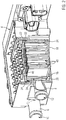
- FIG 1 shows a perspective top view of a housing identified by reference number 2 of an electrical heating device designed as a water heater.
- the housing 2 has a housing trough element 4 made of plastic. In the present case, this plastic is a thermoset.
- the housing 2 forms an inlet connection 6 and an outlet connection 8, which in the present case are formed in one piece on the housing trough element 4.
- the sockets 6, 8 are designed as hose connection sockets and form an inlet opening 10 or an outlet opening 12 for a circulation chamber identified by reference numeral 14.
- the circulation chamber 14 is divided into two heating chambers, of which in the Figures 1 and 2 only the front heating chamber 16 can be seen in the illustration.
- the circulation chamber 14 is subdivided by a dividing wall 20 which is formed in one piece on the housing trough element 4 and projects inwardly from the bottom 18 thereof and which is continued by a further dividing wall 24 formed on a cover plate identified by reference number 22 and identified by reference number 24.
- the two heating chambers 16 are connected to one another by a connecting channel which, in the second exemplary embodiment, corresponds to a housing 2 Figure 5 can be recognized and is identified there with reference numeral 26.
- This connecting channel 26 is formed by a channel wall segment 28, which is integrally formed on the cover plate 22 and extends at right angles to the dividing wall 20, and a channel wall segment 30, which protrudes from the bottom 18 of the housing trough element 4, separated from the heating chamber 16.
- the cover plate 22 is made of plastic.
- the cover plate 22 is formed from a thermoset.
- thermosets for the production of the housing 2 or parts thereof has the advantage that a thermoset has a relatively high temperature resistance of about 150 ° C and shows no brittleness even at temperatures of -40 ° C. This results in better temperature resistance for a housing formed wholly or partially from a thermosetting plastic for requirements that arise in heating operation and when operating vehicles in arctic regions.
- the thermoset is also preferable to a thermoplastic, since a thermoset has better tracking resistance than a thermoplastic.
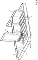
- the Figure 4 shows the cover plate 22 without the housing trough element 4.
- the cover plate 22 has a circumferential edge 32 which interacts with a circumferential groove 34 formed on the housing trough element 4.
- This groove 34 is filled with adhesive, in the present case epoxy adhesive, before the edge 32 penetrates into the groove 34 in order to glue the cover element 22 to the housing trough element.
- the segments 24 and 28 are joined to the corresponding wall elements 20 and 30 of the housing trough element 4.
- the circulation chamber 14 is enclosed in a fluid-tight manner between the bottom 18 of the housing trough element 4 and the cover element 22 and circumferentially surrounded by walls which are formed by the housing trough element 4 and which extend at right angles to the bottom 18 thereof.
- the cover 22 in the from Figures 3 and 4 evident way equipped with PTC heating elements 40 Before assembly, the cover 22 in the from Figures 3 and 4 evident way equipped with PTC heating elements 40.
- the PTC heating elements 40 are plugged into female plug-in element receptacles 44 on the connection side, ie where the PTC heating elements 40 each have two contact tongues 42, which are formed in one piece by the cover plate 22.
- These plug-in element receptacles 44 are each provided at the end with a longitudinal slot 46 which is penetrated by the contact tongues 42 (cf. Figures 1 . 3 ).
- a longitudinal slot 46 forms an example of a passage opening recessed in the cover plate 22 as an example of an inner wall.
- the Figure 4 illustrates the insertion of the PTC heating element 40 into the female plug-in element receptacle 44.
- the PTC heating element 40 has a sealing collar 48 for the plug-in connection made when plugging in, which is designed to match the dimensions of the plug-in element receptacle 44 and is formed by an elastomer material which is inside the plug element receptacle 44 is pressed in a sealing manner, so that the slots 46 are sealed in a fluid-tight manner with respect to the circulation chamber 14.
- the PTC heating element 40 is held frictionally within the plug-in element receptacle 44, and also in the plug-in direction which corresponds to the longitudinal direction of the contact tongues 42. Assembled in this way, the PTC heating elements 40 hold on the cover plate 22, even if this is oriented with the plug-in element receptacles 44 downward, as is shown in FIG Figure 3 is pictured.
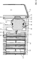
- the Figure 5 illustrates in a sectional view the essence of an embodiment of a housing base part, which is identified by reference numeral 50.
- the housing base part 50 forms walls identified by reference numeral 52, which surround the circulation chamber 16 circumferentially, ie, surround the heating chambers 16 and the connecting channel 26 circumferentially.
- the cover plate 22, which is provided as a separate component in the previously described exemplary embodiment, is in this case formed in one piece by the housing base part 50 and, as in the first exemplary embodiment, also forms a dividing wall 54 here, which separates the circulation chamber 16 from a connection chamber 56, in which all are present Contact tongues 42 of all PTC heating elements 40 are exposed.
- Walls also identified by reference number 58 and surrounding the connection chamber circumferentially are formed by the housing base part 50.
- housing base part 50 which surrounds a control chamber 62 circumferentially.
- a control chamber base identified by reference numeral 64 from which the walls 60 rise, is partially formed by one of the walls 52 and one of the walls 58.
- the housing base part accordingly appears to be H-shaped in cross-section with a U attached to the H on one side.
- the housing base part 50 is formed from plastic and as a unitary component. In the present case, the housing base part 50 is formed from a thermoset.
- the walls 52, 58, 60 are each provided on the end face with a circumferential groove 66, 68, 70.
- the function of these grooves 66, 68, 70 is determined in particular by Figure 6 clarified.
- a cover element 72 to the control chamber 62 is shown there, which is designed as an essentially flat plate with a circumferential rim 74.
- This ring 74 engages in the associated groove 70 and displaces the adhesive introduced there (in the present case epoxy adhesive).
- the rim 74 forms an outer edge of a counter groove 76, which is formed on the cover element 72 and is delimited on the inside by an inner web 78.
- a type of labyrinth seal is thus formed, into which displaced adhesive can penetrate, which has been introduced either into the groove 70 or the counter groove 76 before the cover element 72 is installed.
- the housing covers 80 to the circulation chamber 14 and 82 to the connection chamber 56 are formed on the edge and fastened to the housing base part 50 and sealed against it.
- control chamber bottom 64 is provided with a through opening 84, into which a heat sink 86 is introduced.
- a sealing ring 88 is provided between the heat sink 86 and the inner peripheral wall of the through opening 84.
- the heat sink 86 forms an annular stop 90 on the control housing side, which abuts against the front end face of the through opening 84, which extends in the direction of the control chamber 62 as a projecting collar 92 and is formed by the material of the housing base part 50.
- the outer circumferential surface of the heat sink 86 which is essentially cylindrical at least in the direction of the circulation chamber 14, is circumferentially protruded on opposite sides by locking projections 94, which cooperate with locking lugs 96, which project beyond the essentially cylindrical through opening 84, in order to form a bayonet lock , by which the heat sink 86 is fixed relative to the housing base part 50.
- the sealing ring 88 can be designed such that it holds this locking under axial and / or radial prestress.
- control chamber bottom 64 can be provided with troughs adjacent to the opening into the passage opening 84 on the side of the circulation chamber 14, in which the locking projections 94 engage and which hold the heat sink 86 in a form-locked manner to prevent the bayonet lock 94, 96 from being unintentionally released.
- the Figure 7 provides a view into a control housing trough formed by the control chamber floor 64 and the walls 60, which is closed by the cover element 72 in the final assembled state.
- FIG. 5 shows above the partition 54 a connection trough 100 formed by the partition 54 and the walls 58 Figure 5 underlying side is formed by the housing base part 50 a circulation trough 102 formed by the partition wall 54 and the walls 52.
- the housing base part 50 thus essentially forms all the chambers 14, 56, 52, which are only covered by the cover elements 72, 80, 82 have to be in order to create a functional electrical heating device formed as a lightweight component made of plastic.
- the Figure 8 illustrates a busbar 104, which is provided as an electrical conduction path between the connection chamber 56 and the control chamber 62. At the level of the control chamber floor 64 and within it, the busbar 104 is bent twice in opposite directions by 90 °.
- One end of the busbar 104 located within the control chamber 62 is designed as a plug-in connection for a printed circuit board 106 provided inside the control chamber (cf. Figure 6 ).
- the other end is provided within the connection chamber as a connecting tongue 108 for a distributor plate provided within the connection chamber and omitted in the previous figures.
- the distributor plate can according to EP 2 505 931 A1 be trained.
- a plurality of busbars 108 are exposed within the connection chamber 56 by a plurality of busbars 104 which are provided in an identical manner one behind the other.
- the connecting tongues 108 extend parallel to the contact tongues 42 to the PTC heating elements. In this way, the distributor plate can be sunk into the connection chamber from above for contacting with all contact or connection tongues 42, 108.
- the sheet metal strips 128 are formed from stamped sheets and represent exemplary embodiments for contact sheets.
- the Figure 9 shows a partially sectioned illustration of the housing 2 described above.
- This plastic housing 2 is surrounded by two metal shells 110, 112, which form a shield for the electrical heating device, so that electromagnetic radiation cannot be emitted by the latter.
- the parting plane of the metal shells 110, 112 is located approximately at the middle level of the two connecting pieces 6, 8.
- the metal shells 110, 112 surround the housing 2 essentially completely.
- Fastening projections 114 formed only on the plastic housing 2 protrude outwards through recesses 115 formed on the metal shells 110, 112 over the metal shells 110, 112 and the shielding formed thereby.
- connector housings identified by reference numerals 116 and 118 protrude, the connector housing 116 being provided for the present high-voltage power current and the connector housing 118 being intended for the control lines operated at low voltage.
- the embodiment shown allows the housing 2 to be fastened via the fastening elements 110 made of plastic. With this, the requirement can be met in a simple manner, the housing 2 to the desired one Place to fasten within a motor vehicle.
- the metal shells 110, 112 are essentially continuous. They can just as well be formed from a perforated plate without losing the effect of the metal shells 110, 112 as EMC protection.
- PTC heating element as a frame element
- a PTC element 120 is shown, which is covered with an insulating layer 124 on its opposite main side surfaces 122.
- the insulating layer 124 is a ceramic plate made of aluminum oxide. However, it can also be applied as a coating to the PTC element 120 or can be implemented as a combination of a coating with a single-layer or multi-layer insulating layer.
- the PTC element 120 is designed as a plate with a width B or a length L which is greater by a factor of at least 10 than the thickness D, which corresponds to the distance between the two main side surfaces 122.
- sheet metal strips 128 are provided on opposite end faces 126, which are glued to the PTC element 120 and are electrically conductive on a surface metallization of the PTC element 128, which are applied as protection by means of PVD or CVD can, are connected. These metal strips each form conductor tracks with different polarities, with which the PTC element 120 is energized.
- the sheet metal strips 12 consist of a contact web 130, which is relatively narrow, and the contact tongue 42, which is widened in the width B direction in relation to the contact web 130.
- the contact webs 130 form the electrodes for the PTC element and are electrically connected to the metallization of the PTC element 120.
- the thickness of the contact tongue 42 is less than the thickness of the contact web 30. Its thickness is in turn less than the thickness D of the PTC element.
- the sheet metal strip 128 is provided such that it does not project beyond the main side surfaces 122 of the PTC element 120 at any point.
- the insulating layers 124 protrude laterally beyond the PTC element 120.
- the insulating layers 124 accordingly have a base area that is larger than the base area of the main side surfaces 122 of the PTC element 120. Accordingly, the outer edges of the insulating layers 124 receive the contact web 130 between them on both sides (cf.
- Each contact web 130 is glued to one of the opposite end face surfaces 126.
- the insulating layer 124 is also glued to the PTC element 120.
- the insulating layer 124 lies directly on the PTC element.
- One of the insulation layers 124 thus makes direct contact with the associated main side surface 122 of the PTC element.
- the outside of the respective sheet metal strips 128 is completely flat and extends strictly in the direction of the length L.
- the contact tongues 42 are larger in the width direction than the contact web 130 and project beyond the PTC element 120 towards one another (cf. Figure 10 ).
- the contact tongue 42 is also thinner than the contact web 130.
- the area of the sheet metal strip 128 which is widened compared to the contact web 130 is accommodated in a heating element housing 134 which surrounds the PTC element 120 in the form of a frame.
- This plastic frame 134 encloses the peripheral edges of the insulating layers 124. The edge surfaces 132 are also sealed by the material forming the plastic frame 134.
- the plastic frame 134 is formed as an elastomeric plastic frame 134 by injection molding around an elastomer material. In the finished PTC heating element 40, only the contact tongues 42 project beyond the plastic frame 134 on one end face. All other functional parts of the PTC heating element 40, which are used for heat generation and current conduction, are accommodated within the plastic frame 134.
- the PTC element 120 with its opposite main side surfaces 122 lies behind frame openings identified by reference number 136 and formed by the plastic frame 134. These frame openings 136 are covered by the insulating layer 124. In the present case, there is almost no overlap of the plastic frame 134 with the main side surfaces 122 of the PTC element, so that the latter is exposed to almost 100% of its main side surfaces 122 behind the frame openings 136.
- the frame spars of the plastic frame 134 projecting at right angles from the sealing collar 48 are each provided with system webs 137 on the edge.
- the contact webs 137 are designed in the manner of tapered lamellae, which have a thickness tapered in relation to the thickness of the plastic frame 134.
- the PTC heating elements 40 are in each case slightly offset from one another, so that each first PTC heating element 40 bears on the left side against a wall of the housing 2 and is sealed there by means of the contact web 137 which bears against a boundary wall of the circulation chamber 14 ,
- no fluid can flow past the PTC element 40 on this side, but it can flow past the PTC heating element located upstream or downstream in the flow direction.
- This rests with its abutment web 137 on the opposite side against the wall delimiting the circulation chamber 14 and there it displaces the flow channel.
- a meandering flow channel is thus formed by alternately arranging the PTC heating elements 40.
- the plastic frame 134 also forms the sealing collar 48 already described, which is provided with segments 138 tapering towards the free end of the contact tongues 42 (cf. Figure 13 ). In the present case, three of these segments 138 are provided one behind the other in the longitudinal direction of the contact tongue 42.
- An annular stop 140 is formed through the heating element housing 134 between the frame opening 136 and these segments 138. How Figure 13 illustrates, this stop lies sealingly against a cylindrical counter surface 142 formed by the female plug element receptacle 44.
- the opposite side of the PTC elements 40 lies against the bottom 18 of the housing 2 after installation.
- depressions 144 are provided in the base 18, in which the end faces of the heating element housing 134 are received. This ensures that the PTC heating elements 40 are positioned exactly at right angles relative to the partition 54. Furthermore, a holding force is generated which prevents the PTC heating elements 40 connected in the partition 54 from falling out of the female connector element receptacles 44 during operation and in particular due to the vibration of the vehicle.
- This bottom-side installation of the PTC heating elements 40 also secures the contact pressure within the plug-in contact of the PTC heating elements, so that they securely and also permanently seal the longitudinal slots 46 to the connection chamber 56.
- a contact web 137 can also be provided on the underside of the plastic frame 134 opposite the sealing collar 48, which supports itself under elastic compression against the bottom 18 of the housing 2 and seals there. This not only creates a fluid-tight seal between the underside of the PTC heating element 40 and the housing 2. Rather, the compression of the contact web also generates a compressive force which the PTC heating element 40 holds captively in the female plug-in element receptacle 44 even when strong vibrations act on the electrical heating device.
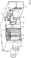
- the Figures 14-16 illustrate the electrical connection of the PTC heating elements 40 using the example of a further embodiment. It shows Figure 15 the embodiment without the housing 2 and parts thereof, similar to the illustration in Figure 3 ,
- busbars 146, 148, 150 provided, which have contact projections 152 formed by stamping and bending, which bear against the contact tongues 42 under elastic prestress and contact them.
- the contact projections 152 protrude into receiving openings 154, which are recessed in the sheet metal strips of the busbars 146, 148, 150.
- the busbar identified by reference numeral 148 has a corresponding receiving opening 154 with contact projections 152 for the busbar 104.
- the busbars identified by reference numerals 146 and 148 are each equipped with a power transistor 156, which is connected in an electrically conductive manner to the corresponding busbar 146, 150 and mounted thereon is.
- the power transistors 156 are connected on the input side to feeders 158, likewise in the form of busbars, which in turn are provided with receiving openings 154 with contact projections 152 for contacting via a busbar 104 in each case. Thereafter, the electrical conduction within the confinement chamber 56 takes place solely through sheet metal elements. These sheet metal elements are exclusively equipped with the power transistors 156 as electrical or electronic components. No further electrical or electronic components are provided.
- these metal plates 146, 148, 150, 158 are inserted electrically insulated from one another in the connection chamber 56 and positioned there.
- the control signals processed on the circuit board 106 for driving the power transistors 146 are fed to the respective power transistor 156 via at least one of the feeders 158.
- the Figure 16 illustrates a sectional view at the same level as in Figure 15 heat sink identified by reference numeral 86.
- An electrical insulating layer 160 for example made of Kapton or a ceramic plate, is implemented between the heat sink 86 and the power transistor 156.
- the busbar 146, 150 provided between this insulating layer 160 and the power transistor 156 leads to a certain spreading of the heat given off by the power transistor 156.
- the busbar 146 or 150 can be formed with a greater thickness, at least in the region of the power transistor 156. It is equally possible to shape the busbar 146 or 150 from copper and thus from a highly thermally conductive material.
- the sheet metal material can have an increased thickness in the region of the power transistor 156 due to contour rolling.
- the busbars 146, 148, 150, 158 can be stamped with a crimping tab or the like that interacts with the housing 2 to attach the respective busbar 146, 148, 150, 158 to the housing 2 and / or the power transistor 146 under tension against the heat sink 86 to press.
- the Figure 16 also shows a variant of the PTC heating element 40. Thereafter, the contact tongues 42 are received within the plastic frame 134 in a fastening plug 162 formed from a hard plastic component. The contact tongues 42 are received in the fastening plug 162 by injection molding.
- the fastening plug 162 is made of a hard plastic with good tracking and dielectric strength.
- the fastening plug 162 forms a hard core for the male plug element formed by the PTC heating element 40.
- This fastening plug 162 is only covered by a thin coating of the soft, elastic material of the sealing collar 48, as a result of which the compression force formed by the sealing collar 48 within the female plug-in element receptacle 44 is increased.
- the fastening plug 162 can be made, for example, by overmolding two sheet metal strips 128, which each form the contact webs 130 and the contact tongues 42 as a one-piece component. Prepared in this way and physically positioned relative to one another, the fastening plug 162 together with the sheet metal strip 128 can be overmolded with the soft-elastic plastic component to form the plastic frame 134, as previously described.
- each individual contact tongue 42 can be arranged in a cylindrical sealing collar with a basically circular or oval cross-sectional area.
- the female plug element receptacle 44 is then likewise provided with a circular or oval cross section.
- Such a configuration can increase the tightness compared to the specifically described embodiment.
- polygonal cross-sectional areas are also possible.
- FIG 16 also shows the attachment of the heat sink 86 within the partition 54.
- the heat sink 86 has, at the level of the partition 54, on its outer circumference a fastening collar 164 which projects beyond the edge of the heat sink 86 and which is sealed in a form-fitting manner by overmolding the plastic material forming the partition 54.
- the design of the fastening collar 164 also improves the tightness between the circulation chamber 14 and the connection chamber 56.
- the surface of the heat sink 86 which projects to the connection chamber 56 can also be covered by the plastic material forming the partition 54.
- a thin film can be formed by means of injection molding between the surface of the heat sink 86 and the interior of the connection chamber 56, via which the power transistor 156 bears against the heat sink 68 in an electrically insulated manner. This further simplifies production. A separate electrical insulation layer need not be provided between the power transistor 156 and the heat sink 86.
Landscapes
- Engineering & Computer Science (AREA)
- Physics & Mathematics (AREA)
- Thermal Sciences (AREA)
- Mechanical Engineering (AREA)
- Chemical & Material Sciences (AREA)
- Combustion & Propulsion (AREA)
- General Engineering & Computer Science (AREA)
- Ceramic Engineering (AREA)
- Resistance Heating (AREA)
- Air-Conditioning For Vehicles (AREA)
- Thermistors And Varistors (AREA)
Description
- Die vorliegende Erfindung betrifft ein PTC-Heizelement nach dem Oberbegriff von Anspruch 1. Ein solches PTC-Heizelement ist aus der
EP 1 768 458 A1 bekannt. - Ein solches PTC-Heizelement ist beispielsweise auch aus der
EP 2 607 121 A1 bekannt. Bei diesem vorbekannten PTC-Heizelement handelt es sich um das PTC-Heizelement eines Luftheizers. In einem das Heizelementgehäuse ausbildenden Positionsrahmen sind mehrere PTC-Elemente aufgenommen, die an gegenüberliegenden Hauptseitenflächen mit einem Kontaktblech kontaktiert sind, welche mit dem Positionsrahmen verrastet sind. An einer Stirnseite wird das Heizelementgehäuse von Anschlussstutzen überragt, die einteilig an dem Heizelementgehäuse angeformt sind und über welche Dichtungshülsen aus Teflon mit einer an der Außenumfangsfläche vorgesehenen Labyrinthdichtung gezogen sind. An der den PTC-Elementen abgewandten Außenseite der Kontaktbleche sind jeweils Isolierlagen aufgebracht, die aus einer Kunststofffolie gebildet sind. - Aus der
EP 1 253 808 A1 bzw.EP 1 395 098 A1 sind ähnliche PTC-Heizelemente bekannt. Bei diesem Stand der Technik wird zumindest einseitig das Kontaktblech zusammen mit der Isolierlage bei der Herstellung des Heizelementgehäuses umspritzt, so dass lediglich die PTC-Elemente in die Öffnung des rahmenförmigen Heizelementgehäuses eingelegt und an der gegenüberliegenden Seite mit dem Kontaktblech und der Isolierung zu überdecken sind. - Eine solche Ausgestaltung stellt zwar gegenüber dem zuvor beschriebenen Stand der Technik eine fertigungstechnische Vereinfachung dar. Der Aufbau ist aber weiterhin relativ raumgreifend und aufwändig. Die vorliegende Erfindung will ein PTC-Element insbesondere für die Kraftfahrzeugindustrie angeben. In Kraftfahrzeugen, insbesondere im Bereich der Elektromobilität, kommen verstärkt PTC-Heizelemente zum Einsatz. Diese müssen sich kostengünstig herstellen lassen und möglichst leicht sein. Des Weiteren ist eine gute Wärmeauskopplung der von dem PTC-Element erzeugten Wärme gewünscht, da die PTC-Elemente selbstregelnde Eigenschaften haben und nur mit schlechtem Wirkungsgrad betrieben werden können, wenn die von dem PTC-Element erzeugte Wärme nur unzureichend abgeführt wird.
- Mit Blick darauf schlägt die vorliegende Erfindung vor, dass der Kunststoffrahmen (134) stoff- und/oder formschlüssig mit der Isolationslage (124) und dem wenigstens einen PTC-Element (120) zwischen den beiden Isolationslagen (124) verbunden ist.
- Der Kunststoffrahmen nach der vorliegenden Erfindung umrandet die Isolationslage und bevorzugt einen sehr schmalen Randbereich des PTC-Elementes, deckt aber das PTC-Element nicht vollständig ab. Hinter den durch den Kunststoffrahmen definierten Rahmenöffnungen liegen die Hauptseitenflächen des PTC-Elementes. Es versteht sich, dass das PTC-Element vorliegend an seinen Hauptseitenflächen ganz oder überwiegend, regelmäßig das PTC-Element allseitig überragend von der Isolationslage überdeckt wird.
- Das erfindungsgemäße PTC-Heizelement kann auf konventionelle Weise bestromt werden. Dabei liegen an den sich gegenüber liegenden Hauptseitenflächen des PTC-Elementes Blechstreifen auf, die bevorzugt einteilig die Kontaktzungen der elektrischen Steckverbindung ausbilden. Diese Kontaktbleche können ganz oder teilweise die Hauptseitenfläche des PTC-Elementes abdecken. An der der Hauptseitenfläche des PTC-Elementes gegenüberliegenden Seite liegt in der Regel die Isolationslage unmittel an dem Kontaktblech an.
- Der spritzgegossene Positionsrahmen wird durch Umspritzen der Isolationsplatten mit dem PTC-Element zwischen den Isolationsplatten angeordnet hergestellt. Der Kunststoffrahmen ist bevorzugt als einteiliges Bauteil ausgebildet. Der Kunststoffrahmen definiert bevorzugt die Außenumfangsfläche des PTC-Heizelementes, welche lediglich an einer vorbestimmten Seite durch die beiden Kontaktzungen überragt. Diese Seite ist die Anschlussseite des PTC-Heizelementes zum Anschluss an eine Steuer- oder Anschlussplatine. An dieser Seite kann der Kunststoffrahmen durch das Rahmenmaterial selbst ein Steckelement, bevorzugt das männliche Steckelement einer Steckverbindung ausbilden. Das Steckelement ist dabei so ausgebildet, dass das PTC-Element mechanisch in einer Steckelementaufnahme befestigt werden kann, d.h. die Befestigung des PTC-Elementes auch in Einsteckrichtung allein durch die Ausgestaltung des Heizelementgehäuses bewirkt wird. So kann das PTC-Element allein aufgrund der Steckverbindung in einer Halterung der Steckverbindung, beispielsweise einer Trennwand, die eine Zirkulationskammer von einer Anschlusskammer trennt, gehalten sein. Der Kunststoffrahmen kann aus Silikon gebildet sein.
- Um diese Steckverbindung möglichst auch fluiddicht auszubilden und auch im Hinblick auf eine gute Abdichtung und Einsiegelung des PTC-Elementes innerhalb des Heizelementgehäuses wird gemäß einer bevorzugten Weiterbildung der vorliegenden Erfindung der Kunststoffrahmen aus einem elastomeren Kunststoff gebildet. Bei diesem Kunststoff handelt es sich bevorzugt nicht um einen TPE, sondern um einen vernetzenden Elastomer. Aufgrund der Elastizität des elastomeren Kunststoffs kann die Steckverbindung so ausgebildet werden, dass sich gute Haltekräfte ergeben und des Weiteren eine solide beispielsweise flüssigkeitsdichte Abdichtung im Bereich der Steckverbindung erzeugt wird.
- Bei der erfindungsgemäßen Lösung liegt die Isolierlage bevorzugt unmittelbar an dem PTC-Element an oder ist unmittelbar darauf beispielsweise als Beschichtung aufgebracht. Gegenüber dem vorbekannten Stand der Technik gemäß
EP 2 607 121 A1 erfolgt dementsprechend die elektrische Versorgung des PTC-Elementes hauptsächlich oder überwiegend über die Stirnseite, d.h. über einander gegenüberliegende Ränder des PTC-Elementes, die sich üblicherweise rechtwinklig zu der Haupterstreckungsrichtung der Isolationsplatte erstrecken. - Das erfindungsgemäße PTC-Heizelement ist in der Regel ein eigenständiges und mit einer Trennwand einer Heizvorrichtung zu verbindendes Element. Der Kunststoffrahmen bildet regelmäßig das elleinige und einzige Gehäuse des PTC-Heizelementes aus, das allein von den Steckverbindungen überragt ist. Jenseits dessen gibt der Kunststoffrahmen in der Regel die äußeren Abmessungen des erfindungsgemäßen PTC-Heizelementes vor.
- Erfindungsgemäß liegen die Isolierlagen in gegenüberliegenden Rahmenöffnungen frei, d.h. bilden zusammen mit dem Material des Kunststoffrahmens die Außenfläche des PTC-Heizelementes. Die beiden Hauptseitenflächen des zumindest einen PTC-Elementes innerhalb des Heizelementgehäuses sind mit diesen Isolationsplatten abgedeckt und liegen bevorzugt unmittelbar daran an.
- Die Isolierlagen können aus einer ein- oder mehrschichtigen Isolierplatte gebildet sein, die im Wesentlichen die gesamte Hauptseitenfläche des PTC-Elementes abdeckt, diese regelmäßig überdeckt, d.h. zumindest einseitig, bevorzugt mehrseitig und besonders bevorzugt vollumfänglich das PTC-Element überragt. Die Isolierlage kann beispielsweise durch eine Kombination einer Keramikplatte mit einer Kunststoffplatte gebildet sein. Die Isolierlage kann aber auch beispielsweise durch Beschichten des PCT-Elementes mit einem elektrisch isolierenden Material ausgebildet sein. In diesem Fall bildet das PTC-Element das Substrat aus, und die Außenfläche der Isolierlage liegt üblicherweise innerhalb des Kunststoffrahmens frei, so dass sich ein guter Wärmeaustrag der von dem PCT-Element erzeugten Wärme ergibt. Als Beschichtung kommt beispielsweise eine keramische Beschichtung in Frage, die mittels PVD oder CVD auf dem PTC-Element als Subtrat aufgebracht ist. Eine als isolierende Beschichtung auf die Hauptseitenfläche des PTC-Elementes aufgebrachte Isolierlage kann mit einer Isolierplatte aus Keramik und/oder Kunststoff kombiniert werden.
- Die Bestromung des zumindest einen PTC-Elementes erfolgt in an sich bekannter Weise bevorzugt über einen Blechstreifen. Dieser bildet als einteiliges Bauteil sowohl die Kontaktzunge, als auch die elektrisch mit dem PTC-Element verbundene Elektrode aus. Diese Elektrode ist regelmäßig nicht die durch PVD oder CVD auf der Oberfläche des PTC-Elements aufgebrachte und daran anhaftende Metallisierung. Diese ist Teil des PTC-Elementes. Zur Kontaktierung hat der Blechstreifen einen elektrisch leitenden und an dem PTC-Element anliegenden Kontaktsteg, der üblicherweise in Längserstreckungsrichtung des Kontaktsteges durch die Kontaktzunge verlängert ist, die das Heizelementgehäuse außenseitig überragt. Alle übrigen Teile des PTC-Elementes sind durch Umspritzen des Kunststoffs entweder eingesiegelt oder innerhalb der Rahmenöffnung vorgesehen.
- Zur Herstellung des PTC-Elementes nach der vorliegenden Erfindung wird bevorzugt an gegenüberliegenden Randflächen der Blechstreifen elektrisch leitend mit dem PTC-Element verklebt. Es können auch mehrere PTC-Elemente mit dem Blechstreifen auf diese Weise verklebt sein. Die PTC-Elemente können mit Abstand zueinander vorgesehen sein, um im mittleren Bereich des PTC-Heizelementes eine Überhitzung zu vermeiden. Der Blechstreifen hat aber zumindest im Bereich des Steges eine etwas geringere Dicke als das PTC-Element. In dieser Weise vorbereitet, wird an gegenüberliegenden Hauptseitenflächen des oder der PTC-Elemente eine Isolationsplatte aufgelegt.
- Die Isolationslage ist oder umfasst bevorzugt eine Isolationsplatte, beispielsweise eine Keramikplatte, da diese eine relativ gute Wärmeleitfähigkeit hat. Die Isolationsplatte wird bevorzugt so aufgelegt, dass diese das oder die PTC-Elemente über den gesamten Umfang überragt und an denjenigen Stellen, wo sich der Blechstreifen befindet, diesen teilweise überdeckt. Die Isolationsplatte kann mit dem Blechstreifen und/oder dem PTC-Element durch Kleben verbunden bzw. vorläufig daran fixiert werden. Die so vorbereitete Einheit wird in eine Spritzgießform gegeben, in deren Formnest die Hauptseitenflächen der Isolationsplatte im Wesentlichen zwischen den Werkzeughälften geklemmt werden. Lediglich ein Randbereich zur Ausbildung des Kunststoffrahmens bleibt umfänglich um das PTC-Element und den Blechstreifen als umlaufender Ringkanal frei. In diesen Ringkanal wird danach Kunststoff, bevorzugt elastomerer Kunststoff eingespritzt, der vernetzt und damit aushärtet bzw. abbbindet. Nachdem eine hinreichende Formsteifigkeit des Kunststoffs erreicht ist, wird das fertige Erzeugnis aus der Spritzgießform entformt. Für das schonende Abdichten der Hauptseitenflächen der Isolierplatte kann die Spritzgussform in geschlossenem Zustand mit der Isolierplatte zusammenwirkende Flächen aufweisen die aus einem weichen, bevorzugt weichelastischen Material gebildet sind, beispielsweise einem Duroplasten. Das Spritzgießen des den Kunststoffrahmen ausbildenden Materials erfolgt bei relativ geringen Drücken.
- Gemäß einer bevorzugten Weiterbildung der vorliegenden Erfindung ist der Kunststoffrahmen an seiner Außenseite mit einem verjüngten Anlagesteg versehen. Dieser Anlagesteg ist in Dickenrichtung des Kunststoffrahmens verjüngt ausgebildet. Der Anlagesteg ist üblicherweise zumindest an einem Rahmenholm des Kunststoffrahmens vorgesehen. Besonders bevorzugt ist der Anlagesteg an drei aufeinander folgenden Außenseiten bzw. Rahmenholmen des Kunststoffrahmens vorgesehen. An der den Kontaktflächen gegenüber liegenden Seite des Kunststoffrahmens bildet der unterseitige Anlagesteg eine Abdichtung gegenüber dem Boden eines Heizergehäuses. Die sich dazu rechtwinklig ersteckenden randseitigen Anlagestege dienen der Abdichtung gegenüber einer seitlichen Wand des Heizergehäuses. So können die PTC-Elemente alternierend versetzt vorgesehen sein, so dass jedes erste PTC-Heizelement an einer, beispielsweise linken Seite an dem Heizergehäuse anliegt, wohingegen jedes zweite PTC-Heizelement an der gegenüberliegenden, rechten Gehäusewand anliegt. Hierdurch wird auf einfache Weise an mäandrierender Strömungskanal gebildet. Die randseitigen Anlagestege dichten das PTC-Heizelement gegenüber dem Heizergehäuse ab. Der Anlagesteg ist bevorzugt einteilig ausgeformt, d.h. integraler Bestandteil des spritzgegossenen Kunststoffrahmens. Insbesondere der untere Anlagesteg kann auch als Kompressionselement genutzt werden, um nach Einbau des erfindungsgemäßen PTC-Heizelementes in das Heizergehäuse eine bestimmte Einbaulage durch elastische Vorspannkraft zu sichern. Diese Sicherung kann eine mechanische Sicherung sein, um das PTC-Heizelement mechanisch an dem Heizergehäuse festzulegen. Die Vorspannkraft kann aber auch oder ergänzend für eine zuverlässige Kontaktierung der Kontaktzungen durch Vorspannung des PTC-Heizelementes sorgen.
- Die vorliegende Erfindung bietet die Möglichkeit, ein PTC-Heizelement wirtschaftlich herzustellen, indem die Kontaktzungen zusammen mit den Elektroden und dem wenigstens einen PTC-Element vormontiert und abgedeckt von Isolationsplatten an gegenüberliegenden Hauptseitenflächen des PTC-Elementes in eine Spritzgießform eingesetzt werden, in welcher der Kunststoffrahmen ausgebildet wird. Dieser wird bevorzugt durch ein Elastomer gebildet, so dass der Kunststoffrahmen auch Dichtmittel für eine Steckverbindung ausbilden kann, deren bevorzugt männliches Steckelement durch das PTC-Heizelement selber gebildet wird. Der elastomere Kunststoff hat ferner den Vorteil, dass der Kunststoffrahmen die Isolationsplatte und gegebenenfalls die Blechstreifen zur Bestromung des bzw. der PTC-Elemente dauerelastisch einsiegelt. Da die Isolationsplatte bevorzugt unmitttelbar an dem PTC-Element anliegt und dementsprechend die Bestromung des PTC-Elementes stirnseitig erfolgt, wird die von dem PTC-Element erzeugte Wärme bestmöglich ausgekoppelt. Das PTC-Heizelement ist leicht. Es lässt sich wirtschaftlich herstellen.
- Das PTC-Heizelement der vorliegenden Erfindung ist insbesondere ein PTC-Heizelement für einen Wasserheizer, wie er beispielsweise aus der
EP 2 797 381 A1 bekannt ist und der eine Zirkulationskammer aufweist, die fluiddicht insbesondere wasserdicht ausgebildet ist und in der zu erwärmende Flüssigkeit zirkulieren kann, die über eine Trennwand von einer Anschlusskammer getrennt ist, in welcher die Kontaktzungen des PTC-Heizelementes freiliegen. Bevorzugt sind mehrere PTC-Heizelemente als Teil dieser elektrischen Heizvorrichtung vorgesehen. Durch die Wahl von elastomerem Kunststoff zur Ausbildung des Kunststoffrahmens kann das erfindungsgemäße PTC-Heizelement in die Trennwand eingesteckt werden, um die Kontaktzungen in der Anschlusskammer anzuordnen und die Zirkulationskammer aufgrund der Steckverbindung gegenüber der Anschlusskammer abzudichten. Die Steckverbindung erlaubt auch eine Halterung des PTC-Heizelementes in Einsteckrichtung, so dass die Trennwand zunächst mit sämtlichen PTC-Heizelementen bestückt werden kann, um die so vormontierte Einheit zu handhaben und schließlich das Heizergehäuse unter Einschluss des bzw. der PTC-Heizelemente zu schließen. - Weitere Einzelheiten und Vorteile der vorliegenden Erfindung ergeben sich aus der nachfolgenden Beschreibung eines Ausführungsbeispiels in Verbindung mit der Zeichnung. In dieser zeigen:
- Figur 1
- eine perspektivische Draufsicht auf ein erstes Ausführungsbeispiel eines Gehäuses;
- Figur 2
- eine perspektivische Seitenansicht des in
Figur 1 gezeigten Ausführungsbeispiels; - Figur 3
- eine in dem ersten Ausführungsbeispiel vorgesehene Abdeckplatte 22 in isolierter Darstellung zusammen mit PTC-Heizelementen;
- Figur 4
- die in
Figur 3 gezeigte Abdeckplatte beim Bestücken mit einem PTC-Heizelement; - Figur 5
- eine seitliche perspektivische Schnittansicht eines zweiten Ausführungsbeispiels der vorliegenden Erfindung;
- Figur 6
- das Detail VI gemäß der Darstellung in
Figur 5 ; - Figur 7
- eine perspektivische Sicht in die Steuerwanne des zweiten Ausführungsbeispiels;
- Figur 8
- eine perspektivische Längsschnittansicht entlang der Linie VIII-VIII gemäß der Darstellung in
Figur 7 ; - Figur 9
- eine perspektivische, teilweise aufgebrochene Seitenansicht des zweiten Ausführungsbeispiels mit einer an dem Kunststoffgehäuse vorgesehenen Abschirmung;
- Figur 10
- eine perspektivische Seitenansicht von Teilen des PTC-Heizelementes;
- Figur 11
- eine teilweise gebrochene perspektivische Seitenansicht des PTC-Heizelementes;
- Figur 12
- eine perspektivische Querschnittsansicht des PTC-Heizelementes;
- Figur 13
- eine Längsschnittansicht durch die Abdeckplatte gemäß den
Figuren 3 ,4 mit einem einzelnen darin aufgenommenen PTC-Heizelement; - Figur 14
- eine perspektivische Seitenansicht bei entfernten Gehäusedeckel eines weiteren Ausführungsbeispiels;
- Figur 15
- eine Ansicht ähnlich zu
Figur 14 ohne Gehäusedeckel des weiteren Ausführungsbeispiels und - Figur 16
- eine perspektivische Schnittansicht durch die Trennwand des weiteren Ausführungsbeispiels.
-
Figur 1 zeigt eine perspektivische Draufsicht auf ein mit Bezugszeichen 2 gekennzeichnetes Gehäuse einer als Wasserheizer ausgebildeten elektrischen Heizvorrichtung. Das Gehäuse 2 hat ein Gehäusewannenelement 4 aus Kunststoff. Dieser Kunststoff ist vorliegend ein Duroplast. Das Gehäuse 2 bildet einen Einlassstutzen 6 und einen Auslassstutzen 8 aus, die vorliegend einteilig an dem Gehäusewannenelement 4 ausgebildet sind. Die Stutzen 6, 8 sind als Schlauchanschlussstutzen ausgebildet und bilden eine Einlassöffnung 10 bzw. eine Auslassöffnung 12 zu einer mit Bezugszeichen 14 gekennzeichneten Zirkulationskammer aus. Die Zirkulationskammer 14 ist in zwei Heizkammern geteilt, von denen in denFiguren 1 und2 lediglich die in der Darstellung vordere Heizkammer 16 zu erkennen ist. Die Unterteilung der Zirkulationskammer 14 erfolgt durch eine einteilig an dem Gehäusewannenelement 4 ausgebildete und von dessen Boden 18 nach innen abragende Teilungswand 20, die durch eine an einer mit Bezugszeichen 22 gekennzeichneten Abdeckplatte ausgebildete und mit Bezugszeichen 24 gekennzeichnete weitere Teilungswand 24 ihre Fortsetzung findet. An der den beiden Stutzen 6, 8 gegenüberliegenden Seite sind die beiden Heizkammern 16 durch einen Verbindungskanal miteinander verbunden, der in dem zweiten Ausführungsbeispiel eines Gehäuses 2 gemäßFigur 5 zu erkennen und dort mit Bezugszeichen 26 gekennzeichnet ist. Dieser Verbindungskanal 26 wird durch ein Kanalwandsegment 28, welches einteilig an der Abdeckplatte 22 angeformt ist und sich rechtwinklig zu der Teilungswand 20 erstreckt, und ein Kanalwandsegment 30, welches von dem Boden 18 des Gehäusewannenelementes 4 abragt, von der Heizkammer 16 getrennt. - Die Abdeckplatte 22 ist aus Kunststoff hergestellt. Vorliegend ist die Abdeckplatte 22 aus einem Duroplasten gebildet. Grundsätzlich hat die Verwendung von Duroplasten zur Herstellung des Gehäuses 2 oder Teile davon den Vorteil, dass ein Duroplast eine relativ hohe Temperaturbeständigkeit von etwa 150°C hat und auch bei Temperaturen von -40 °C keine Sprödigkeit zeigt. Damit ergibt sich für ein aus einem Duroplasten ganz oder teilweise gebildeten Gehäuse eine bessere Temperaturbeständigkeit bei Anforderungen, die im Heizbetrieb und beim Betrieb von Fahrzeugen in arktischen Regionen auftreten. Der Duroplast ist aber auch zu bevorzugen gegenüber einem Thermoplasten, da ein Duroplast eine bessere Kriechstrom-Festigkeit als ein Thermoplast hat.
- Die
Figur 4 zeigt die Abdeckplatte 22 ohne das Gehäusewannenelement 4. Die Abdeckplatte 22 hat einen umlaufenden Rand 32, der mit einer an dem Gehäusewannenelement 4 ausgebildeten umlaufenden Nut 34 zusammenwirkt. Diese Nut 34 ist mit Kleber, vorliegend Epoxidkleber gefüllt, bevor der Rand 32 in die Nut 34 eindringt, um das Abdeckelement 22 mit dem Gehäusewannenelement zu verkleben. In gleicher Weise werden die Segmente 24 bzw. 28 mit den korrespondierenden Wandelementen 20 bzw. 30 des Gehäusewannenelementes 4 gefügt. Danach ist die Zirkulationskammer 14 fluiddicht zwischen dem Boden 18 des Gehäusewannenelementes 4 und dem Abdeckelement 22 und umfänglich umgeben von Wandungen eingeschlossen, die durch das Gehäusewannenelement 4 gebildet sind und die sich rechtwinklig zu dessen Boden 18 erstrecken. - Vor der Montage wird das Abdeckelement 22 in der aus den
Figuren 3 und4 ersichtlichen Weise mit PTC-Heizelementen 40 bestückt. Die PTC-Heizelemente 40 sind dazu anschlussseitig, d.h. dort, wo die PTC-Heizelemente 40 jeweils zwei Kontaktzungen 42 aufweisen, in weibliche Steckelementaufnahmen 44 eingesteckt, die durch die Abdeckplatte 22 einteilig ausgebildet werden. Diese Steckelementaufnahmen 44 sind jeweils endseitig mit einem Längsschlitz 46 versehen, der von den Kontaktzungen 42 durchragt wird (vgl.Figuren 1 ,3 ). Ein Längsschlitz 46 bildet ein Beispiel einer in der Abdeckplatte 22 als Beispiel einer Innenwand ausgesparten Durchtrittsöffnung aus. - Die
Figur 4 verdeutlicht das Einstecken des PTC-Heizelementes 40 in die weibliche Steckelementaufnahme 44. Das PTC-Heizelement 40 hat für die beim Einstecken gefügte Steckverbindung einen Dichtkragen 48, der an die Abmessung der Steckelementaufnahme 44 angepasst ausgebildet ist und durch ein Elastomermaterial gebildet ist, welches innerhalb der Steckelementaufnahme 44 dichtend verpresst wird, so dass die Schlitze 46 gegenüber der Zirkulationskammer 14 fluiddicht abgedichtet sind. Darüber hinaus wird durch das Verpressen des den Dichtkragen 48 bildenden Materials das PTC-Heizelement 40 reibschlüssig innerhalb der Steckelementaufnahme 44 gehalten, und zwar auch in Steckrichtung, die der Längserstreckungsrichtung der Kontaktzungen 42 entspricht. In dieser Weise gefügt halten die PTC-Heizelemente 40 an der Abdeckplatte 22, auch wenn diese mit den Steckelementaufnahmen 44 nach unten ausgerichtet ist, wie dies inFigur 3 dargestellt wird. - Die
Figur 5 verdeutlicht in einer Schnittansicht das Wesen eines Ausführungsbeispiels eines Gehäusebasisteils, welches mit Bezugszeichen 50 gekennzeichnet ist. Das Gehäusebasisteil 50 bildet mit Bezugszeichen 52 gekennzeichnete Wandungen, die die Zirkulationskammer 16 umfänglich umgeben, d.h. die Heizkammern 16 und den Verbindungskanal 26 umfänglich umgeben. Die bei dem vorher beschriebenen Ausführungsbeispiel als separates Bauteil vorgesehene Abdeckplatte 22 ist vorliegend einteilig durch das Gehäusebasisteil 50 ausgebildet und bildet auch hier - wie bei dem ersten Ausführungsbeispiel - eine Trennwand 54 aus, die die Zirkulationskammer 16 von einer Anschlusskammer 56 trennt, in welcher vorliegend sämtliche Kontaktzungen 42 sämtlicher PTC-Heizelemente 40 freiliegen. Auch mit Bezugszeichen 58 gekennzeichnete und die Anschlusskammer umfänglich umgebende Wandungen werden durch das Gehäusebasisteil 50 ausgebildet. Schließlich werden in Verlängerung der Stutzen 6, 8 und in dieser Richtung hinter der Zirkulationskammer 16 bzw. der Anschlusskammer 56 durch das Gehäusebasisteil 50 Wandungen 60 gebildet, die eine Steuerkammer 62 umfänglich umgeben. Ein mit Bezugszeichen 64 gekennzeichneter Steuerkammerboden, von dem sich die Wandungen 60 erheben, wird teilweise durch eine der Wandungen 52 und eine der Wandungen 58 gebildet. In einer Querschnittsansicht, die parallel zu der Erstreckungsrichtung der Stutzen 6, 8 verläuft, erscheint das Gehäusebasisteil dementsprechend als im Querschnitt H-förmig mit einem einseitig an das H angesetzten U. Das Gehäusebasisteil 50 ist aus Kunststoff und als einheitliches Bauteil ausgebildet. Das Gehäusebasisteil 50 ist vorliegend aus einem Duroplasten gebildet. - Die Wandungen 52, 58, 60 sind jeweils stirnseitig mit einer umlaufenden Nut 66, 68, 70 versehen. Die Funktion dieser Nuten 66, 68, 70 wird insbesondere durch
Figur 6 verdeutlicht. So ist dort ein Abdeckelement 72 zu der Steuerkammer 62 dargestellt, welches als im Wesentlichen ebene Platte mit einem umlaufenden Kranz 74 ausgebildet ist. Dieser Kranz 74 greift in die zugehörige Nut 70 ein und verdrängt dort eingebrachten Kleber (vorliegend Epoxidkleber). Der Kranz 74 bildet einen äußeren Rand einer Gegennut 76, die an dem Abdeckelement 72 ausgeformt und innenseitig durch einen inneren Steg 78 begrenzt ist. Somit ist eine Art Labyrinthdichtung gebildet, in welche verdrängter Kleber eindringen kann, der vor der Montage des Abdeckelementens 72 entweder in die Nut 70 oder die Gegennut 76 eingebracht worden ist. In entsprechender Weise sind die Gehäusedeckel 80 zu der Zirkulationskammer 14 bzw. 82 zu der Anschlusskammer 56 randseitig ausgebildet und an dem Gehäusebasisteil 50 befestigt und dagegen abgedichtet. - Wie ebenfalls
Figur 6 verdeutlicht, ist der Steuerkammerboden 64 mit einer Durchgangsöffnung 84 versehen, in die ein Kühlkörper 86 eingebracht ist. Zur Abdichtung der Zirkulationskammer 14 gegenüber der Steuerkammer 62 ist zwischen dem Kühlkörper 86 und der Innenumfangswandung der Durchgangsöffnung 84 ein Dichtring 88 vorgesehen. Der Kühlkörper 86 bildet steuergehäuseseitig einen ringförmigen Anschlag 90 aus, der gegen die stirnseitige Endfläche der Durchgangsöffnung 84 anliegt, die in Richtung auf die Steuerkammer 62 als vorspringender Kragen 92 verlängert und durch das Material des Gehäusebasisteils 50 ausgebildet ist. - Wie
Figur 7 erkennen lässt, wird die zumindest in Richtung auf die Zirkulationskammer 14 im Wesentlichen zylindrisch ausgebildete Außenumfangsfläche des Kühlkörpers 86 an gegenüberliegenden Seiten umfänglich von Verriegelungsvorsprüngen 94 überragt, die mit Verriegelungsnasen 96, die innenumfänglich die im Wesentlichen zylindrische Durchgangsöffnung 84 überragen, zusammenwirken, um einen Bajonettverschluss auszubilden, durch den der Kühlkörper 86 gegenüber dem Gehäusebasisteil 50 festgelegt ist. Der Dichtring 88 kann so ausgebildet sein, dass er diese Verriegelung unter axialer und/oder radialer Vorspannung hält. Zusätzlich kann der Steuerkammerboden 64 benachbart zu der Mündung in die Durchgangsöffnung 84 auf Seiten der Zirkulationskammer 14 mit Mulden versehen sein, in welche die Verriegelungsvorsprünge 94 eingreifen und die den Kühlkörper 86 formschlüssig drehgesichert halten, um ein unbeabsichtigtes Lösen des Bajonettverschlusses 94, 96 zu verhindern. - Die
Figur 7 gibt den Blick in eine durch den Steuerkammerboden 64 und die Wandungen 60 gebildete Steuergehäusewanne frei, die im endmontierten Zustand durch das Abdeckelement 72 verschlossen ist. - Die
Figur 5 zeigt oberhalb der Trennwand 54 eine durch die Trennwand 54 und die Wandungen 58 gebildete Anschlusswanne 100. Auf der in der Darstellung nachFigur 5 darunterliegenden Seite ist durch das Gehäusebasisteil 50 eine durch die Trennwand 54 und die Wandungen 52 gebildete Zirkulationswanne 102 ausgeformt. So bildet das Gehäusebasisteil 50 im Wesentlichen sämtliche Kammern 14, 56, 52, die lediglich durch die Abdeckelemente 72, 80, 82 abgedeckt werden müssen, um eine funktionsfähige und als Leichtbauteil aus Kunststoff ausgeformte elektrische Heizvorrichtung zu schaffen. - Die
Figur 8 verdeutlicht eine Stromschiene 104, die als elektrische Leitungsbahn zwischen der Anschlusskammer 56 und der Steuerkammer 62 vorgesehen ist. Auf Höhe des Steuerkammerbodens 64 und innerhalb desselben ist die Stromschiene 104 zweifach gegenläufig um 90° umbogen. Ein innerhalb der Steuerkammer 62 befindliches Ende der Stromschiene 104 ist als Steckanschuss für eine innerhalb der Steuerkammer vorgesehene bestückte Leiterplatte 106 ausgebildet (vgl.Figur 6 ). Das andere Ende ist innerhalb der Anschlusskammer als Anschlusszunge 108 für eine innerhalb der Anschlusskammer vorgesehene und in den vorherigen Figuren weggelassene Verteilerplatte vorgesehen. Die Verteilerplatte kann gemäßEP 2 505 931 A1 ausgebildet sein. Durch mehrere hintereinander in identischer Weise vorgesehene Stromschienen 104 liegen mehrere Anschlusszungen 108 innerhalb der Anschlusskammer 56 frei. Die Anschlusszungen 108 erstrecken sich parallel zu den Kontaktzungen 42 zu den PTC-Heizelementen. So kann die Verteilerplatte zur Kontaktierung mit sämtlichen Kontakt- bzw. Anschlusszungen 42, 108 in die Anschlusskammer von oben eingesenkt werden. - Die Blechstreifen 128 sind aus stanzbearbeiteten Blechen gebildet und stellen Ausführungsbeispiele für Kontaktbleche dar.
- Die
Figur 9 zeigt eine teilweise geschnittene Darstellung des zuvor beschriebenen Gehäuses 2. Dieses Kunststoffgehäuse 2 wird durch zwei Metallschalen 110, 112 umgeben, die eine Abschirmung der elektrischen Heizvorrichtung ausbilden, so dass elektromagnetische Strahlen nicht von dieser abgesetzt werden können. Die Teilungsebene der Metallschalen 110, 112 befindet sich in etwa auf mittlerer Höhe der beiden Stutzen 6, 8. Die Metallschalen 110, 112 umgeben das Gehäuse 2 im Wesentlichen vollumfänglich. Lediglich an dem Kunststoffgehäuse 2 ausgebildete Befestigungsvorsprünge 114 ragen durch an den Metallschalen 110, 112 ausgebildete Ausnehmungen 115 über die Metallschalen 110, 112 und die dadurch gebildete Abschirmung nach außen vor. Des Weiteren überragen mit Bezugszeichen 116 bzw. 118 gekennzeichnete Steckergehäuse, wobei das Steckergehäuse 116 für den vorliegend hochvoltigen Leistungsstrom und das Steckergehäuse 118 für die mit niedriger Voltage betriebenen Steuerleitungen vorgesehen ist. Die inFigur 9 gezeigte Ausführung erlaubt die Befestigung des Gehäuses 2 über die aus Kunststoff gebildeten Befestigungselemente 110. Mit diesem kann auf einfache Weise dem Erfordernis entsprochen werden, das Gehäuse 2 an der gewünschten Stelle innerhalb eines Kraftfahrzeuges zu befestigen. InFigur 9 sind die Metallschalen 110, 112 im Wesentlichen durchgehend ausgebildet. Sie können ebenso gut aus einem Lochblech gebildet sein, ohne dass die Wirkung der Metallschalen 110, 112 als EMV-Schutz verlorenginge. - In
Figur 10 ist ein PTC-Element 120 gezeigt, welches an seinen aneinander gegenüberliegenden Hauptseitenflächen 122 mit einer Isolierlage 124 belegt ist. Die Isolierlage 124 ist vorliegend eine Keramikplatte aus Aluminiumoxid. Sie kann aber auch als Beschichtung auf das PTC-Element 120 aufgebracht sein oder als Kombination einer Beschichtung mit einer ein- bzw. mehrschichtigen Isolierschicht verwirklicht sein. Das PTC-Element 120 ist als Plättchen ausgebildet mit einer Breite B bzw. einer Länge L, die um den Faktor von zumindest 10 größer sind, als die Dicke D, die dem Abstand der beiden Hauptseitenflächen 122 entspricht. Sich im Wesentlichen in Richtung der Länge L erstreckend sind an sich gegenüberliegenden Stirnseitenflächen 126 jeweils Blechstreifen 128 vorgesehen, die mit dem PTC-Element 120 verklebt und elektrisch leitend an einer oberflächigen Metallierung des PTC-Elements 128, die als Schutz mittels PVD oder CVD aufgebracht sein kann, angebunden sind. Diese Blechstreifen bilden jeweils Leiterbahnen zu unterschiedlichen Polaritäten aus, mit denen das PTC-Element 120 bestromt wird. Die Blechstreifen 12 bestehen aus einem Kontaktsteg 130, der relativ schmal ist, und der gegenüber dem Kontaktsteg 130 in Richtung der Breite B verbreiterten Kontaktzunge 42. - Die Kontaktstege 130 bilden vorliegend die Elektroden zu dem PTC-Element aus und sind mit der Metallisierung des PTC-Elements 120 elektrisch verbunden. Die Dicke der Kontaktzunge 42 ist geringer als die Dicke des Kontaktsteges 30. Dessen Dicke ist wiederum geringer als die Dicke D des PTC-Elementes. Der Blechstreifen 128 ist so vorgesehen, dass dieser an keiner Stelle die Hauptseitenflächen 122 des PTC-Elementes 120 überragt. Wie die
Figuren 11 und insbesondere 12 erkennen lassen, ragen die Isolierlagen 124 seitlich über das PTC-Element 120 hinaus. Die Isolierlagen 124 haben demensprechend eine Grundfläche, die größer als die Grundfläche der Hauptseitenflächen 122 des PTC-Elementes 120 ist. Dementsprechend nehmen die äußeren Ränder der Isolierlagen 124 beidseitig den Kontaktsteg 130 zwischen sich auf (vgl.Figur 12 ). Jeder Kontaktsteg 130 ist mit einer der gegenüberliegenden Stirnseitenflächen 126 verklebt. Die Isolierlage 124 ist ebenfalls mit dem PTC-Element 120 verklebt. Die Isolierlage 124 liegt unmittelbar auf dem PTC-Element auf. So kontaktiert eine der Isolierlagen 124 die zugehörige Hauptseitenfläche 122 des PTC-Elementes unmittelbar. - Die Außenseite der jeweiligen Blechstreifen 128 ist vollkommen eben und erstreckt sich streng in Richtung der Länge L. Die Kontaktzungen 42 sind in Breitenrichtung größer als der Kontaktsteg 130 ausgebildet und überragen das PTC-Element 120 aufeinander zu (vgl.
Figur 10 ). Die Kontaktzunge 42 ist auch dünner als der Kontaktsteg 130. - Der gegenüber dem Kontaktsteg 130 verbreiterte Bereich des Blechstreifens 128 ist in einem Heizelementgehäuse 134 aufgenommen, welches rahmenförmig das PTC-Element 120 umgibt. Dieser Kunststoffrahmen 134 schließt die umlaufenden Ränder der Isolierlagen 124 ein. Auch die Randflächen 132 sind von dem den Kunststoffrahmen 134 bildenden Material eingesiegelt. Der Kunststoffrahmen 134 ist durch Umspritzen eines Elastomermaterials als elastomerer Kunststoffrahmen 134 ausgebildet. Bei dem fertigen PTC-Heizelement 40 überragen lediglich die Kontaktzungen 42 an einer Stirnseite den Kunststoffrahmen 134. Alle anderen funktionalen und für die Wärmeerzeugung und Stromführung dienenden Teile des PTC-Heizelementes 40 sind innerhalb des Kunststoffrahmens 134 aufgenommen. Wie insbesondere
Figur 12 verdeutlicht, liegt das PTC-Element 120 mit seinen gegenüberliegenden Hauptseitenflächen 122 hinter mit Bezugszeichen 136 gekennzeichneten und durch den Kunststoffrahmen 134 gebildeten Rahmenöffnungen. Diese Rahmenöffnungen 136 werden bedeckt durch die Isolierlage 124. Vorliegend ergibt sich nahezu überhaupt keine Überdeckung des Kunststoffrahmens 134 mit den Hauptseitenflächen 122 des PTC-Elementes, so dass dieses zu annähernd 100% seiner Hauptseitenflächen 122 hinter den Rahmenöffnungen 136 freiliegt. - Die rechtwinklig von dem Dichtkragen 48 abragenden Rahmenholme des Kunststoffrahmens 134 sind jeweils mit randseitigen Anlagenstegen 137 versehen. Die Anlagestege 137 sind nach Art von verjüngten Lamellen ausgebildet, die eine gegenüber der Dicke des Kunststoffrahmens 134 verjüngte Dicke haben. Wie sich beispielsweise auf
Figur 6 entnehmen lässt, sind die PTC-Heizelement 40 jeweils hintereinander leicht versetzt vorgesehen, so dass jedes erste PTC-Heizelement 40 an der linken Seite an einer Wandung des Gehäuses 2 anliegt und dort über den dichtend gegen eine Begrenzungswand der Zirkulationskammer 14 anliegenden Anlagesteg 137 abgedichtet sind. So kann auf dieser Seite kein Fluid an dem PTC-Element 40 vorbeiströmen, wohl aber an dem in Strömungsrichtung davor bzw. dahinter liegenden PTC-Heizelement. Dieses wiederum liegt mit seinem Anlagesteg 137 an der gegenüber liegenden Seite an der die Zirkulationskammer 14 begrenzten Wandung an und verlegt dort den Strömungskanal. So wird durch alternierendes Anordnen der PTC-Heizelemente 40 ein mäandrierender Strömungskanal ausgebildet. - Der Kunststoffrahmen 134 bildet ferner den zuvor bereits beschriebenen Dichtkragen 48 aus, der mit zu dem freien Ende der Kontaktzungen 42 konisch zulaufenden Segmenten 138 versehen ist (vgl.
Figur 13 ). Vorliegend sind drei dieser Segmente 138 in Längserstreckungsrichtung der Kontaktzunge 42 hintereinander vorgesehen. Zwischen der Rahmenöffnung 136 und diesen Segmenten 138 ist ein ringförmiger Anschlag 140 durch das Heizelementgehäuse 134 ausgebildet. WieFigur 13 verdeutlicht, liegt dieser Anschlag dichtend gegen eine zylindrische und durch die weibliche Steckelementaufnahme 44 gebildete Gegenfläche 142 an. - Wie die
Figuren 2 und5 verdeutlichen, liegt die gegenüberliegende Seite der PTC-Elemente 40 nach dem Einbau an dem Boden 18 des Gehäuses 2 an. Zur genauen Positionierung sind in dem Boden 18 Vertiefungen 144 vorgesehen, in welchen die Stirnseitenflächen des Heizelementgehäuses 134 aufgenommen sind. Dadurch wird eine exakt rechtwinklige Positionierung der PTC-Heizelemente 40 relativ zu der Trennwand 54 gewährleistet. Des Weiteren wird eine Haltekraft erzeugt, die verhindert, dass die in der Trennwand 54 steckverbundenen PTC-Heizelemente 40 beim Betrieb und insbesondere aufgrund der Vibration des Fahrzeuges aus den weiblichen Steckelementaufnahmen 44 herausfallen können. Diese bodenseitige Anlage der PTC-Heizelemente 40 sichert auch die Anpresskraft innerhalb der Steckkontaktierung der PTC-Heizelemente, so dass diese sicher und auch dauerhaft die Längsschlitze 46 zu der Anschlusskammer 56 abdichten. - Es versteht sich von selbst, dass auf die Vertiefungen 144 auch verzichtet werden kann. Ähnlich zu den Anlagestegen 137 kann auch an der dem Dichtkragen 48 gegenüber liegenden Unterseite des Kunststoffrahmens 134 ein Anlagesteg 137 vorgesehen sein, der sich unter elastischer Kompression gegen den Boden 18 des Gehäuses 2 abstützt und dort abdichtet. Hierdurch wird nicht nur eine fluiddichte Abdichtung zwischen der Unterseite des PTC-Heizelementes 40 und dem Gehäuse 2 geschaffen. Vielmehr noch wird durch die Kompression des Anlagesteges auch eine Druckkraft erzeugt, welche das PTC-Heizelement 40 auch dann unverlierbar in der weiblichen Steckelementaufnahme 44 hält, wenn starke Vibrationen auf die elektrische Heizvorrichtung einwirken.
- Die
Figuren 14-16 verdeutlichen den elektrischen Anschluss der PTC-Heizelemente 40 am Beispiel einer weiteren Ausführungsform. Dabei zeigtFigur 15 das Ausführungsbeispiel ohne das Gehäuse 2 und Teile davon, ähnlich zu der Darstellung inFigur 3 . Für den elektrischen Anschluss sind in der Anschlusskammer 56 gestanzte Bleche als Stromschienen 146, 148, 150 vorgesehen, die durch Stanzen und Biegen ausgebildete Kontaktvorsprünge 152 aufweisen, die unter elastischer Vorspannung gegen die Kontaktzungen 42 anliegen und diese kontaktieren. Die Kontaktvorsprünge 152 ragen in Aufnahmeöffnungen 154 hinein, die in den Blechstreifen der Stromschienen 146, 148, 150 ausgespart sind. Die mit Bezugszeichen 148 gekennzeichnete Stromschiene hat eine entsprechende Aufnahmeöffnung 154 mit Kontaktvorsprüngen 152 für die Stromschiene 104. Die mit Bezugszeichen 146 bzw. 148 gekennzeichneten Stromschienen sind jeweils mit einem Leistungstransistor 156 bestückt, der elektrisch leitend mit der entsprechenden Stromschiene 146, 150 verbunden und darauf montiert ist. Die Leistungstransistoren 156 sind eingangsseitig mit ebenfalls als Stromschienen ausgebildeten Zuleitern 158 verbunden, die wiederum Aufnahmeöffnungen 154 mit Kontaktvorsprüngen 152 für die Kontaktierung über jeweils eine Stromschien 104 versehen sind. Danach erfolgt die elektrische Leitung innerhalb der Einschlusskammer 56 allein durch Blechelemente. Diese Blechelemente sind ausschließlich mit den Leistungstransistoren 156 als elektrische bzw. elektronische Bauteile bestückt. Es sind keine weiteren elektrischen bzw. elektronischen Bauteile vorgesehen. - Wie insbesondere
Figur 16 verdeutlicht, sind diese Metallplatten 146, 148, 150, 158 elektrisch voneinander isoliert in die Anschlusskammer 56 eingesetzt und dort positioniert. Die auf der Leiterplatte 106 verarbeiteten Steuersignale zum Ansteuern der Leistungstransistoren 146 werden über zumindest einen der Zuleiter 158 dem jeweiligen Leistungstransistor 156 zugeführt. - Die
Figur 16 verdeutlicht eine Schnittansicht auf Höhe eines auch inFigur 15 mit Bezugszeichen 86 gekennzeichneten Kühlkörpers. Zwischen dem Kühlkörper 86 und dem Leistungstransistor 156 ist eine elektrische Isolierschicht 160 beispielsweise aus Kapton oder einer Keramikplatte verwirklicht. Die zwischen dieser Isolierschicht 160 und dem Leistungstransistor 156 vorgesehene Stromschiene 146, 150 führt zu einer gewissen Spreizung der von dem Leistungstransistor 156 abgegebenen Wärme. Dazu kann die Stromschiene 146 bzw. 150 zumindest im Bereich des Leistungstransistors 156 mit größerer Dicke ausgebildet sein. Ebenso gut ist es möglich, die Stromschiene 146 bzw. 150 aus Kupfer und damit einem gut wärmeleitfähigem Material auszuformen. Das Blechmaterial kann im Bereich des Leistungstransistors 156 durch Konturwalzen eine erhöhte Dicke aufweist. - Die Stromschienen 146, 148, 150, 158 können durch Stanzbearbeitung mit einer Crimplasche oder dergleichen versehen sein, die mit dem Gehäuse 2 in Wechselwirkung tritt, um die jeweilige Stromschiene 146, 148, 150, 158 an dem Gehäuse 2 befestigen und/oder den Leistungstransistor 146 unter Vorspannung gegen den Kühlkörper 86 anzulegen bzw. zu drücken.
- Die
Figur 16 lässt auch eine Variante des PTC-Heizelementes 40 erkennen. Danach sind die Kontaktzungen 42 innerhalb des Kunststoffrahmens 134 in einem aus einer harten Kunststoffkomponente gebildeten Befestigungsstopfen 162 aufgenommen. Die Kontaktzungen 42 sind durch Umspritzen in dem Befestigungsstopfen 162 aufgenommen. Der Befestigungsstopfen 162 besteht aus einem harten Kunststoff mit guten Kriechstrom- und Durchschlagsfestigkeit. Der Befestigungsstopfen 162 bildet einen harten Kern für das durch das PTC-Heizelement 40 gebildete männliche Steckelement. Dieser Befestigungsstopfen 162 ist lediglich durch einen dünnen Überzug aus dem weichelastischen Material des Dichtkragens 48 überzogen, wodurch die durch den Dichtkragen 48 gebildete Kompressionskraft innerhalb der weiblichen Steckelementaufnahme 44 gesteigert wird. Der Befestigungsstopfen 162 kann beispielsweise durch Umspritzen von zwei Blechstreifen 128 erfolgen, die jeweils für sich die Kontaktstege 130 und die Kontaktzungen 42 als einteiliges Bauteil ausformen. In dieser Weise vorbereitet und räumlich-körperlich relativ zueinander positioniert kann der Befestigungsstopfen 162 zusammen mit dem Blechstreifen 128 wie zuvor beschrieben mit der weichelastischen Kunststoffkomponente zur Ausbildung des Kunststoffrahmen 134 überspritzt werden. - Auch bei der Variante nach den
Figuren 14-16 ist der Dichtkragen länglich ausgebildet. Es versteht sich aber von selbst, dass jede einzelne Kontaktzunge 42 in einem zylindrischen Dichtkragen mit im Grunde kreisrunder oder ovaler Querschnittsfläche angeordnet sein kann. Die weibliche Steckelementaufnahme 44 ist dann ebenfalls mit kreisrundem bzw. ovalem Querschnitt versehen. Eine solche Ausgestaltung kann die Dichtigkeit gegenüber dem konkret beschriebenen Ausführungsbeispiel erhöhen. Es versteht sich von selbst, dass auch polygonale Querschnittsflächen möglich sind. -
Figur 16 lässt ferner die Befestigung des Kühlkörpers 86 innerhalb der Trennwand 54 erkennen. Der Kühlkörper 86 hat auf Höhe der Trennwand 54 an seinem Außenumfang einen den Kühlkörper 86 randseitig überragenden Befestigungskragen 164, der durch Umspritzen des die Trenne 54 bildenden Kunststoffmaterials formschlüssig eingesiegelt ist. Die Ausgestaltung des Befestigungskragens 164 verbessert im Übrigen die Dichtigkeit zwischen der Zirkulationskammer 14 und der Anschlusskammer 56. - Gemäß einer nicht dargestellten Variante kann die zu der Anschlusskammer 56 ragende Oberfläche des Kühlkörpers 86 auch von dem die Trennwand 54 ausbildenden Kunststoffmaterial überzogen sein. Beim Überspritzen des Kühlkörpers 46 kann ein dünner Film mittels Spritzgießen zwischen der Oberfläche des Kühlkörpers 86 und dem Innenraum der Anschlusskammer 56 ausgebildet sein, über welchen der Leistungstransistor 156 an dem Kühlkörper 68 elektrisch isoliert anliegt. Hierdurch wird die Fertigung weiter vereinfacht. Eine separate elektrische Isolierlage muss nicht zwischen dem Leistungstransistor 156 und dem Kühlkörper 86 vorgesehen werden.
-
- 2
- Gehäuse
- 4
- Gehäusewannenelement
- 6
- Einlassstutzen
- 8
- Auslassstutzen
- 10
- Einlassöffnung
- 12
- Auslassöffnung
- 14
- Zirkulationskammer
- 16
- Heizkammer
- 18
- Boden
- 20
- Teilungswand
- 22
- Abdeckplatte
- 24
- Teilungswand
- 26
- Verbindungskanal
- 28
- Kanalwandsegment
- 30
- Kanalwandsegment
- 32
- Rand
- 34
- Nut
- 40
- PTC-Heizelement
- 42
- Kontaktzunge
- 44
- weibliche Steckelementaufnahme
- 46
- Längsschlitz
- 48
- Dichtkragen
- 50
- Gehäusebasisteil
- 52
- Wandung
- 54
- Trennwand
- 56
- Anschlusskammer
- 58
- Wandung
- 60
- Wandung
- 62
- Steuerkammer
- 64
- Steuerkammerboden
- 66
- Nut der Zirkulationskammer 14
- 68
- Nut der Anschlusskammer 56
- 70
- Nut der Steuerkammer 62
- 72
- Abdeckelement zu der Steuerkammer 62
- 74
- Kranz
- 76
- Gegennut
- 78
- innerer Steg
- 80
- Gehäusedeckel zu der Zirkulationskammer
- 82
- Gehäusedeckel zu der Anschlusskammer
- 84
- Durchgangsöffnung
- 86
- Kühlkörper
- 88
- Dichtring
- 90
- Anschlag
- 92
- Kragen
- 94
- Verriegelungsvorsprung
- 96
- Verriegelungsnase
- 98
- Steuerwanne
- 100
- Anschlusswanne
- 102
- Zirkulationswanne
- 104
- Stromschiene
- 106
- Leiterplatte
- 108
- Anschlusszunge
- 110
- Metallschale
- 112
- Metallschale
- 114
- Befestigungsvorsprung
- 115
- Ausnehmung
- 116
- Steckergehäuse Hochvolt
- 118
- Steckergehäuse Niedrigvolt
- 120
- PTC-Element
- 122
- Hauptseitenfläche
- 124
- Isolierlage
- 126
- Stirnseitenfläche
- 128
- Blechstreifen
- 130
- Kontaktsteg
- 132
- Randfläche
- 134
- Heizelementgehäuse/Kunststoffrahmen
- 136
- Rahmenöffnung
- 137
- Anlagesteg
- 138
- Segment
- 140
- Anschlag
- 142
- Gegenfläche
- 144
- Vertiefung
- 146
- Stromschiene
- 148
- Stromschiene
- 150
- Stromschiene
- 152
- Kontaktvorsprung
- 154
- Aufnahmeöffnung
- 156
- Leistungstransistor
- 158
- Zuleiter
- 160
- Isolierschicht
- 162
- Befestigungstopfen
- 164
- Befestigungskragen
- B
- Breite des PTC-Elementes
- L
- Länge des PTC-Elementes
- D
- Dicke des PTC-Elementes
Claims (6)
- PTC-Heizelement (40) mit einem Heizelementgehäuse (134), das zumindest ein PTC-Element (120) und das PTC-Element (120) bestromende und Kontaktzungen (42) für eine elektrische Steckverbindung ausformende Kontaktbleche (128) für den elektrischen Anschluss von elektrisch mit dem PTC-Element (120) verbundenen Elektroden (130) als bauliche Einheit fügt, wobei das PTC-Element (120) an seinen beiden Hauptseitenflächen (122) mit je einer Isolationslage (124) abgedeckt ist, wobei das Heizelementgehäuse einen spritzgegossenen Kunststoffrahmen (134) aufweist, der die Isolationslagen (124) lediglich randseitig einfasst und gegenüberliegende Rahmenöffnungen (136) definiert, hinter denen das PTC-Element (120) mit seinen Hauptseitenflächen (122) liegt, und wobei die beiden Isolationslagen (124) in den gegenüberliegenden Rahmenöffnungen (136) freiliegen, dadurch gekennzeichnet, dass der Kunststoffrahmen (134) stoff- und/oder formschlüssig mit den Isolationslagen (124) und dem wenigstens einen PTC-Element (120) zwischen den beiden Isolationslagen (124) verbunden ist.
- PTC-Heizelement (40) nach Anspruch 1, dadurch gekennzeichnet, dass die Isolationslage (124) unmittelbar an dem PTC-Element (120) anliegt oder darauf vorgesehen ist.
- PTC-Heizelement (40) nach einem der vorherigen Ansprüche, dadurch gekennzeichnet, dass das PTC-Element (120) und die Isolationslagen (124) durch Umspritzen des den Kunststoffrahmen (134) bildenden Materials mit dem Kunststoffrahmen (134) verbunden sind.
- PTC-Heizelement (40) nach einem der vorherigen Ansprüche, dadurch gekennzeichnet, dass das den Kunststoffrahmen (134) bildende Material ein elastomerer Kunststoff ist.
- PTC-Heizelement (40) nach einem der vorherigen Ansprüche, dadurch gekennzeichnet,
dass die Kontaktzunge (42) durch einen Blechstreifen (128) gebildet ist, der einen stirnseitig an dem PTC-Element (120) elektrisch leitend anliegenden Kontaktsteg (130) aufweist, sodass die elektrische Versorgung des PTC-Elementes (120) hauptsächlich oder überwiegend über die Stirnseite, d.h. über einander gegenüberliegende Ränder des PTC-Elementes (120), die sich üblicherweise rechtwinklig zu der Haupterstreckungsrichtung der Isolationsplatte erstrecken, erfolgt, und
dass der Kunststoffrahmen (134) die Außenumfangsfläche des PTC-Heizelementes (40) ausbildet, die lediglich an einer Stirnseite durch die beiden Kontaktzungen (42) überragt ist. - PTC-Heizelement (40) nach einem der vorherigen Ansprüche, dadurch gekennzeichnet, dass der Kunststoffrahmen (134) an seiner Außenseite mit einem verjüngten Anlagesteg (137) versehen ist.
Priority Applications (2)
| Application Number | Priority Date | Filing Date | Title |
|---|---|---|---|
| US15/832,171 US10760822B2 (en) | 2016-12-06 | 2017-12-05 | Electric heating device |
| CN201711281275.7A CN108156677B (zh) | 2016-12-06 | 2017-12-06 | 电加热装置 |
Applications Claiming Priority (1)
| Application Number | Priority Date | Filing Date | Title |
|---|---|---|---|
| DE102016224296.2A DE102016224296A1 (de) | 2016-12-06 | 2016-12-06 | Elektrische heizvorrichtung |
Publications (3)
| Publication Number | Publication Date |
|---|---|
| EP3334246A1 EP3334246A1 (de) | 2018-06-13 |
| EP3334246A8 EP3334246A8 (de) | 2018-08-15 |
| EP3334246B1 true EP3334246B1 (de) | 2020-01-08 |
Family
ID=57965817
Family Applications (6)
| Application Number | Title | Priority Date | Filing Date |
|---|---|---|---|
| EP17154764.9A Active EP3334242B1 (de) | 2016-12-06 | 2017-02-06 | Elektrische heizvorrichtung |
| EP19193023.9A Active EP3592105B1 (de) | 2016-12-06 | 2017-02-06 | Elektrische heizvorrichtung |
| EP17154774.8A Active EP3334244B1 (de) | 2016-12-06 | 2017-02-06 | Elektrische heizvorrichtung und ptc-heizelement für eine solche |
| EP17154801.9A Active EP3334245B1 (de) | 2016-12-06 | 2017-02-06 | Elektrische heizvorrichtung und ptc-heizelement einer elektrischen heizvorrichtung |
| EP17154768.0A Active EP3334243B1 (de) | 2016-12-06 | 2017-02-06 | Elektrische heizvorrichtung |
| EP17155418.1A Active EP3334246B1 (de) | 2016-12-06 | 2017-02-09 | Elektrische heizvorrichtung |
Family Applications Before (5)
| Application Number | Title | Priority Date | Filing Date |
|---|---|---|---|
| EP17154764.9A Active EP3334242B1 (de) | 2016-12-06 | 2017-02-06 | Elektrische heizvorrichtung |
| EP19193023.9A Active EP3592105B1 (de) | 2016-12-06 | 2017-02-06 | Elektrische heizvorrichtung |
| EP17154774.8A Active EP3334244B1 (de) | 2016-12-06 | 2017-02-06 | Elektrische heizvorrichtung und ptc-heizelement für eine solche |
| EP17154801.9A Active EP3334245B1 (de) | 2016-12-06 | 2017-02-06 | Elektrische heizvorrichtung und ptc-heizelement einer elektrischen heizvorrichtung |
| EP17154768.0A Active EP3334243B1 (de) | 2016-12-06 | 2017-02-06 | Elektrische heizvorrichtung |
Country Status (4)
| Country | Link |
|---|---|
| US (5) | US10775077B2 (de) |
| EP (6) | EP3334242B1 (de) |
| CN (5) | CN108156673B (de) |
| DE (1) | DE102016224296A1 (de) |
Cited By (1)
| Publication number | Priority date | Publication date | Assignee | Title |
|---|---|---|---|---|
| DE102022205705A1 (de) | 2022-06-03 | 2023-12-14 | Mahle International Gmbh | Heizeinrichtung zum Heizen eines Fluids |
Families Citing this family (79)
| Publication number | Priority date | Publication date | Assignee | Title |
|---|---|---|---|---|
| DE102016224296A1 (de) * | 2016-12-06 | 2018-06-07 | Eberspächer Catem Gmbh & Co. Kg | Elektrische heizvorrichtung |
| DE102017101946A1 (de) * | 2017-02-01 | 2018-08-02 | Epcos Ag | PTC-Heizer mit verringertem Einschaltstrom |
| DE102017208253A1 (de) * | 2017-05-16 | 2018-11-22 | Eberspächer Catem Gmbh & Co. Kg | Verfahren zum Herstellen eines PTC-Heizelementes |
| US10969141B2 (en) * | 2018-03-13 | 2021-04-06 | Ngb Innovations Llc | Regulating temperature and reducing buildup in a water heating system |
| EP3584808B1 (de) | 2018-06-18 | 2021-10-06 | Mahle International GmbH | Ptc-heizmodul zur erwärmung einer flüssigkeit |
| CN109028547A (zh) * | 2018-06-19 | 2018-12-18 | 安徽省宁国市天成电气有限公司 | 一种ptc液体加热控制系统 |
| CN108592408A (zh) * | 2018-06-19 | 2018-09-28 | 安徽省宁国市天成电气有限公司 | 一种ptc加热器用加热组件 |
| CN108716767A (zh) * | 2018-06-19 | 2018-10-30 | 安徽省宁国市天成电气有限公司 | 一种ptc液体加热器总成 |
| DE102018212012A1 (de) | 2018-07-18 | 2020-01-23 | Eberspächer Catem Gmbh & Co. Kg | Wärmeerzeugendes Element und Verfahren zu dessen Herstellung |
| CN109367355A (zh) * | 2018-10-15 | 2019-02-22 | 江苏东方电热器制造有限公司 | 一种新能源汽车用ptc电加热器 |
| DE102018218667A1 (de) * | 2018-10-31 | 2020-04-30 | Mahle International Gmbh | PTC-Heizmodul und ein Verfahren zum Herstellen des PTC-Heizmoduls |
| CN111121297B (zh) * | 2018-11-01 | 2021-06-18 | 东翰生技股份有限公司 | 发热件的电连接固定结构 |
| DE102018221654B4 (de) * | 2018-12-13 | 2025-12-04 | Eberspächer Catem Gmbh & Co. Kg | PTC-Heizelement und Verfahren zu dessen Herstellung |
| CN109654729B (zh) * | 2018-12-17 | 2020-09-29 | 大连理工大学 | 一种多段式气体加热装置 |
| CN109831836B (zh) * | 2018-12-20 | 2021-01-12 | 成都理工大学 | 一种基于面状加热装置的层状物理模型及其制备方法 |
| DE102019202045B4 (de) * | 2019-02-15 | 2020-12-03 | Eberspächer Catem Gmbh & Co. Kg | Elektrische Heizvorrichtung |
| DE102019202543B4 (de) * | 2019-02-26 | 2026-01-08 | Eberspächer Catem Gmbh & Co. Kg | PTC-Heizelement und elektrische Heizvorrichtung mit einem solchen PTC-Heizelement |
| DE102019204665B4 (de) | 2019-03-06 | 2026-05-07 | Eberspächer Catem Gmbh & Co. Kg | PTC-Heizelement und eine elektrische Heizvorrichtung |
| DE102019204401B4 (de) | 2019-03-28 | 2026-01-08 | Eberspächer Catem Gmbh & Co. Kg | PTC-Heizelement und elektrische Heizvorrichtung umfassend ein solches |
| CN213588038U (zh) * | 2019-03-29 | 2021-07-02 | 布瑞威利私人有限公司 | 加热液体的器具 |
| DE102019204472B4 (de) * | 2019-03-29 | 2025-10-09 | Eberspächer Catem Gmbh & Co. Kg | Wärmeerzeugendes Element und elektrische Heizvorrichtung enthaltend ein solches |
| DE102019205848A1 (de) | 2019-04-24 | 2020-10-29 | Eberspächer Catem Gmbh & Co. Kg | PTC-Heizelement und elektrische Heizvorrichtung mit einem solchen PTC-Heizelement und Verfahren zur Herstellung eines PTC-Heizelementes |
| CN112009202B (zh) * | 2019-05-31 | 2024-10-29 | 法雷奥汽车空调湖北有限公司 | 加热装置 |
| CN110435385B (zh) * | 2019-07-10 | 2024-05-10 | 芜湖汉特威电热科技有限公司 | 一种用于新能源汽车空调的混合式加热器暖风芯体 |
| EP3772867B1 (de) * | 2019-08-06 | 2023-05-03 | Eberspächer catem GmbH & Co. KG | Elektrische heizvorrichtung und verfahren zu deren herstellung |
| US11856658B2 (en) * | 2019-08-06 | 2023-12-26 | Eberspächer Catem Gmbh & Co. Kg | Electric heating device |
| US11267354B2 (en) * | 2019-08-16 | 2022-03-08 | DESIGNWERK TECHNOLOGIES GmbH | Power supply |
| DE102019212443B4 (de) * | 2019-08-20 | 2026-01-15 | Eberspächer Catem Gmbh & Co. Kg | Vorrichtung, Verfahren und Verwendung einer PTC-Heizvorrichtung zur Verkürzung der Anlaufzeit eines Verbrennungsmotors |
| DE102019127324A1 (de) * | 2019-10-10 | 2021-04-15 | Borgwarner Ludwigsburg Gmbh | Heizplatte und Durchlauferhitzer mit Heizplatte |
| DE102019217234A1 (de) * | 2019-11-07 | 2021-05-12 | Eberspächer Catem Gmbh & Co. Kg | PTC-Heizeinrichtung und elektrische Heizvorrichtung mit einer solchen PTC- Heizeinrichtung und Verfahren zur Herstellung einer elektrischen Heizvorrichtung |
| DE102019217453B4 (de) * | 2019-11-12 | 2026-02-05 | Eberspächer Catem Gmbh & Co. Kg | PTC-Heizzelle |
| DE102019220591A1 (de) | 2019-12-27 | 2021-07-01 | Eberspächer Catem Gmbh & Co. Kg | Elektrische Heizvorrichtung |
| DE102019220589A1 (de) | 2019-12-27 | 2021-07-01 | Eberspächer Catem Gmbh & Co. Kg | Wärmeerzeugendes Element und Verfahren zu dessen Herstellung |
| EP3866564A3 (de) | 2019-12-27 | 2021-10-13 | Eberspächer catem GmbH & Co. KG | Elektrische heizvorrichtung |
| DE202020000689U1 (de) | 2020-02-19 | 2020-03-16 | Eberspächer Catem Gmbh & Co. Kg | Steuervorrichtung sowie elektrische Heizvorrichtung umfassend eine solche |
| DE102020202195A1 (de) * | 2020-02-20 | 2021-08-26 | Eberspächer catem Hermsdorf GmbH & Co. KG | Elektrische Heizeinrichtung |
| DE102020202453B4 (de) | 2020-02-26 | 2022-09-29 | Eberspächer Catem Gmbh & Co. Kg | Elektrische Heizvorrichtung und Verfahren zu deren Herstellung |
| DE102020202508B4 (de) | 2020-02-27 | 2026-04-23 | Eberspächer catem Hermsdorf GmbH & Co. KG | PTC Heizeinrichtung |
| DE102020203390A1 (de) * | 2020-03-17 | 2021-09-23 | Eberspächer catem Hermsdorf GmbH & Co. KG | Elektrische heizeinrichtung und verfahren zu deren herstellung |
| EP3883336A1 (de) * | 2020-03-20 | 2021-09-22 | Mahle International GmbH | Heizanordnung |
| DE102020205646A1 (de) | 2020-05-05 | 2021-11-11 | Eberspächer Catem Gmbh & Co. Kg | Verwendung einer PTC-Heizeinrichtung |
| DE102020112553A1 (de) | 2020-05-08 | 2021-11-11 | Eberspächer Catem Gmbh & Co. Kg | PTC-Heizeinrichtung und elektrische Heizvorrichtung umfassend eine solche |
| US12049124B2 (en) | 2020-05-15 | 2024-07-30 | Eberspächer Catem Gmbh & Co. Kg | PTC heating assembly and method for manufacturing the same |
| DE102020113402A1 (de) | 2020-05-18 | 2021-11-18 | Eberspächer Catem Gmbh & Co. Kg | Elektrische Heizvorrichtung |
| CN111649474A (zh) * | 2020-06-11 | 2020-09-11 | 安徽江淮松芝空调有限公司 | 一种简易水暖ptc系统 |
| DE102020207712A1 (de) | 2020-06-22 | 2021-12-23 | Eberspächer Catem Gmbh & Co. Kg | Steuervorrichtung |
| DE102020117366A1 (de) | 2020-07-01 | 2022-01-05 | Eberspächer Catem Gmbh & Co. Kg | Elektrische Steuervorrichtung, insbesondere für eine elektrische Heizvorrichtung |
| DE102020208643A1 (de) * | 2020-07-09 | 2022-01-13 | Eberspächer Catem Gmbh & Co. Kg | Heizzelle und PTC-Heizeinrichtung umfassend eine solche |
| EP3945264B1 (de) * | 2020-07-26 | 2025-05-14 | Valeo Autosystemy SP. Z.O.O. | Elektrischer flüssigkeitserhitzer |
| DE102020210284A1 (de) * | 2020-08-13 | 2022-02-17 | Eberspächer Catem Gmbh & Co. Kg | Elektrische Heizvorrichtung und Verfahren zu deren Herstellung |
| CN112113332B (zh) * | 2020-09-11 | 2021-09-14 | 安徽铱玛热能设备制造股份有限公司 | 电磁感应热风炉 |
| DE102021104371A1 (de) * | 2021-02-24 | 2022-08-25 | Audi Aktiengesellschaft | Kraftfahrzeug und Verfahren zur Anpassung einer verfügbaren Heizleistung in einem Kraftfahrzeug |
| DE102021109618A1 (de) | 2021-04-16 | 2022-10-20 | Eberspächer Catem Gmbh & Co. Kg | PTC-Heizeinrichtung |
| FR3123254A1 (fr) * | 2021-05-27 | 2022-12-02 | Valeo Systemes Thermiques | Module de commande et dispositif de chauffage électrique correspondant |
| DE102022110017A1 (de) * | 2021-06-18 | 2022-12-22 | Borgwarner Ludwigsburg Gmbh | Durchlauferhitzer für Automobile |
| DE102022116979A1 (de) | 2022-07-07 | 2024-01-18 | Eberspächer Catem Gmbh & Co. Kg | Elektrische Heizeinrichtung und Verfahren zu dessen Herstellung |
| DE102022116921A1 (de) | 2022-07-07 | 2024-01-18 | Eberspächer Catem Gmbh & Co. Kg | Bauteil einer elektrischen Heizvorrichtung und elektrische Heizvorrichtung |
| DE102022123503A1 (de) | 2022-09-14 | 2024-03-14 | Eberspächer Catem Gmbh & Co. Kg | Elektrische Heizvorrichtung mit einer Anschlusseinrichtung und Verfahren zur Herstellung einer solchen |
| DE102022123568A1 (de) | 2022-09-15 | 2024-03-21 | Eberspächer Catem Gmbh & Co. Kg | Steuervorrichtung und Verfahren zur Herstellung einer Steuervorrichtung |
| DE102022005120A1 (de) | 2022-09-15 | 2024-03-21 | Eberspächer Catem Gmbh & Co. Kg | Steuervorrichtung |
| DE102022123572A1 (de) | 2022-09-15 | 2024-03-21 | Eberspächer Catem Gmbh & Co. Kg | Steuervorrichtung und elektrische Heizvorrichtung umfassend eine solche |
| DE102022125637A1 (de) | 2022-10-05 | 2024-04-11 | Eberspächer Catem Gmbh & Co. Kg | PTC-Heizvorrichtung und Verfahren zu deren Herstellung |
| DE102022127107A1 (de) | 2022-10-17 | 2024-04-18 | Eberspächer Catem Gmbh & Co. Kg | Elektrische Heizvorrichtung und Verfahren zu deren Herstellung |
| DE102022133193A1 (de) * | 2022-12-14 | 2024-06-20 | Vaillant Gmbh | Verfahren zur Herstellung eines Durchlauferhitzers, Durchlauferhitzer und Verwendung von elektrisch leitfähigen Streifen |
| DE102023102629A1 (de) | 2023-02-02 | 2024-08-08 | Eberspächer Catem Gmbh & Co. Kg | Elektrische Heizvorrichtung und Verfahren zu deren Herstellung |
| DE102023103296A1 (de) | 2023-02-10 | 2024-08-14 | Eberspächer Catem Gmbh & Co. Kg | Elektrische Heizvorrichtung und Verfahren zu deren Herstellung |
| DE102023104034A1 (de) | 2023-02-17 | 2024-08-22 | Eberspächer Catem Gmbh & Co. Kg | Elektrische Heizvorrichtung und Anordnung aus einer Leiterplatte und einem Anschlussstück |
| EP4422347B1 (de) * | 2023-02-23 | 2025-11-26 | Valeo Systemes Thermiques | Heizeinrichtung |
| DE102023105053A1 (de) | 2023-03-01 | 2024-09-05 | Eberspächer Catem Gmbh & Co. Kg | Elektrische Heizvorrichtung |
| DE102023106515A1 (de) * | 2023-03-15 | 2024-09-19 | Eberspächer Catem Gmbh & Co. Kg | Elektrische Heizvorrichtung |
| DE102023106460A1 (de) * | 2023-03-15 | 2024-09-19 | Eberspächer Catem Gmbh & Co. Kg | Elektrische Heizvorrichtung |
| DE102023121416A1 (de) | 2023-08-10 | 2025-02-13 | Eberspächer Catem Gmbh & Co. Kg | Elektrische Heizvorrichtung |
| DE102023121383A1 (de) | 2023-08-10 | 2025-02-13 | Eberspächer Catem Gmbh & Co. Kg | Elektrische Heizvorrichtung |
| DE102023121379A1 (de) | 2023-08-10 | 2025-02-13 | Eberspächer Catem Gmbh & Co. Kg | Elektrische Heizvorrichtung und elektrische Heizeinrichtung |
| DE102024105184A1 (de) * | 2024-02-23 | 2025-08-28 | Eberspächer Catem Gmbh & Co. Kg | Elektrische Heizvorrichtung |
| DE102024105187A1 (de) * | 2024-02-23 | 2025-08-28 | Eberspächer Catem Gmbh & Co. Kg | Elektrische Heizvorrichtung |
| DE102024115839A1 (de) * | 2024-06-06 | 2025-12-11 | Eberspächer Catem Gmbh & Co. Kg | Elektrische Heizvorrichtung |
| DE102024116220A1 (de) * | 2024-06-11 | 2025-12-11 | Eberspächer Catem Gmbh & Co. Kg | Elektrische Heizvorrichtung |
| US12302460B1 (en) | 2024-08-22 | 2025-05-13 | Datec Coating Technologies Ltd. | Self-limiting thick film positive temperature coefficient of resistivity (PTCR) resistor compositions |
Family Cites Families (76)
| Publication number | Priority date | Publication date | Assignee | Title |
|---|---|---|---|---|
| US760076A (en) * | 1903-01-22 | 1904-05-17 | George I Leonard | Electric heater. |
| US3086187A (en) | 1960-05-20 | 1963-04-16 | American Radiator & Standard | Electrical heating element |
| US3414704A (en) * | 1965-02-25 | 1968-12-03 | Texas Instruments Inc | Self-regulating heating device |
| JPS5553100Y2 (de) * | 1975-11-07 | 1980-12-09 | ||
| US4086467A (en) | 1976-07-19 | 1978-04-25 | Texas Instruments Incorporated | Electronic heater for high voltage applications |
| US4091267A (en) * | 1976-07-19 | 1978-05-23 | Texas Instruments Incorporated | Self-regulating electric heater |
| DE2845965C2 (de) * | 1978-10-21 | 1983-01-20 | Fritz Eichenauer GmbH & Co KG, 6744 Kandel | Elektrisches Widerstandsheizelement |
| EP0026457B1 (de) * | 1979-09-28 | 1983-10-19 | Siemens Aktiengesellschaft | Heizeinrichtung mit Kaltleiter-Heizelement |
| DE2948591A1 (de) * | 1979-12-03 | 1981-06-11 | Fa. Fritz Eichenauer, 6744 Kandel | Durchlauferhitzer |
| US4759189A (en) * | 1985-12-02 | 1988-07-26 | Design & Manufacturing Corporation | Self-limiting thermal fluid displacement actuator |
| CN2102053U (zh) * | 1991-04-17 | 1992-04-22 | 刘存胜 | 屏蔽毯 |
| ES2086434T3 (es) * | 1991-07-03 | 1996-07-01 | David & Baader Dbk Spezfab | Dispositivo calentador de ptc. |
| ES2098394T3 (es) * | 1992-06-23 | 1997-05-01 | David & Baader Dbk Spezfab | Radiador. |
| US5293844A (en) * | 1993-06-04 | 1994-03-15 | Aos Holding Company | Protective shield for the electrical components of a water heater |
| US5922233A (en) | 1994-09-14 | 1999-07-13 | Sekisui Kasethin Kogyo Kabushiki Kaisha | Heater and manufacturing method thereof |
| GB9602873D0 (en) * | 1996-02-13 | 1996-04-10 | Dow Corning Sa | Heating elements and process for manufacture thereof |
| CN1228238A (zh) * | 1997-01-13 | 1999-09-08 | 出光兴产株式会社 | 平面状发热体 |
| DE19738318C5 (de) | 1997-09-02 | 2014-10-30 | Behr Gmbh & Co. Kg | Elektrische Heizeinrichtung für ein Kraftfahrzeug |
| DE29825093U1 (de) * | 1997-09-02 | 2004-10-07 | Behr Gmbh & Co. Kg | Elektrische Heizeinrichtung, insbesondere für ein Kraftfahrzeug |
| DE59911409D1 (de) * | 1999-06-15 | 2005-02-10 | David & Baader Dbk Spezfab | Heizvorrichtung zur Lufterwärmung |
| ES2187411T3 (es) | 2000-05-23 | 2003-06-16 | Catem Gmbh & Co Kg | Dispositivo calefactor electrico, especialmente para la aplicacion en automoviles. |
| AU2001282459A1 (en) * | 2000-08-22 | 2002-03-04 | A.T.C.T.-Advanced Thermal Chips Technologies Ltd. | Liquid heating method and apparatus particularly useful for vaporizing a liquid condensate from cooling devices |
| DE20023727U1 (de) * | 2000-12-05 | 2005-10-27 | Dbk David + Baader Gmbh | Durchlauferhitzer für Scheibenwischwasser |
| EP1213197A1 (de) | 2000-12-05 | 2002-06-12 | David + Baader DBK GmbH | Durchlauferhitzer für Scheibenwischwasser |
| DE10208472A1 (de) * | 2002-02-27 | 2003-09-25 | Bsh Bosch Siemens Hausgeraete | Haushaltsgerät |
| DE50213799D1 (de) | 2002-09-02 | 2009-10-08 | Eberspaecher Catem Gmbh & Co K | Elektrische Heizung für Kraftfahrzeuge |
| FR2858166B1 (fr) * | 2003-07-23 | 2005-09-09 | Valeo Climatisation | Radiateur electrique integrant des elements chauffants a coefficient de temperature positif |
| KR100445722B1 (ko) * | 2003-11-18 | 2004-08-26 | 우리산업 주식회사 | 히트 로드 조립체 및 이를 포함하는 차량용 프리히터 |
| DE502004005781D1 (de) * | 2004-02-10 | 2008-02-07 | Catem Gmbh & Co Kg | Elektrische Heizvorrichtung für niedrige Bauhöhen |
| US7064301B2 (en) * | 2004-03-22 | 2006-06-20 | Halla Climate Control Corporation | Electric heater |
| DE102004033258A1 (de) * | 2004-07-09 | 2006-02-02 | Hydac Filtertechnik Gmbh | Armatur zur Bildung eines fluidführenden Anschlusses |
| DE102004034323A1 (de) * | 2004-07-15 | 2006-02-16 | Hexion Specialty Chemicals Gmbh | Duroplastgebundene Faserformteile und Verfahren zu ihrer Herstellung |
| EP1768459B1 (de) | 2005-09-23 | 2008-05-21 | Catem GmbH & Co. KG | Wärmeerzeugendes Element einer Heizvorrichtung |
| EP1916875B1 (de) | 2005-09-23 | 2010-11-24 | Eberspächer catem GmbH & Co. KG | Wärmeerzeugendes Element einer Heizvorrichtung |
| ES2303167T3 (es) * | 2005-09-23 | 2008-08-01 | CATEM GMBH & CO. KG | Elemento generador de calor de un dispositivo calefactor. |
| ES2354964T3 (es) | 2006-06-28 | 2011-03-21 | EBERSPÄCHER CATEM GMBH & CO. KG | Dispositivo de calefacción eléctrico. |
| EP1931176B1 (de) | 2006-10-25 | 2011-10-05 | Eberspächer catem GmbH & Co. KG | Eine elektrische Heizvorrichtung und Verfahren zur Herstellung derselben |
| CN201066202Y (zh) | 2007-05-29 | 2008-05-28 | 巫嘉雄 | 车用流体加热器 |
| US20110062137A1 (en) * | 2007-07-18 | 2011-03-17 | Chia-Hsiung Wu | Vehicular fluid heater |
| CN101598362B (zh) * | 2009-06-22 | 2011-09-28 | 浙江世友木业有限公司 | 一种木质地热地板采暖方法及地热地板 |
| DE202009009942U1 (de) * | 2009-07-20 | 2010-09-09 | Schneider, Helmut | Elektrodenkessel |
| KR101318636B1 (ko) * | 2010-06-14 | 2013-10-16 | 한라비스테온공조 주식회사 | 탄소나노튜브 발열체를 이용한 히터 |
| CN101945505A (zh) * | 2010-08-31 | 2011-01-12 | 上海吉龙经济发展有限公司 | 一种双重水路密封的ptc加热器 |
| EP2440005B1 (de) * | 2010-10-08 | 2015-12-23 | Eberspächer catem GmbH & Co. KG | Elektrische Heizvorrichtung und Verfahren zur Herstellung |
| EP2440004B1 (de) * | 2010-10-08 | 2015-02-25 | Eberspächer catem GmbH & Co. KG | Elektrische Heizvorrichtung |
| EP2440006B1 (de) * | 2010-10-08 | 2015-02-25 | Eberspächer catem GmbH & Co. KG | Elektrische Heizvorrichtung |
| DE102011003296A1 (de) | 2011-01-28 | 2012-08-02 | Behr Gmbh & Co. Kg | Wärmeübertrager |
| DE102011014626A1 (de) * | 2011-03-21 | 2012-09-27 | Eichenauer Heizelemente Gmbh & Co. Kg | Elektrische Heizeinrichtung |
| EP2626647B1 (de) | 2011-03-30 | 2014-06-11 | Eberspächer catem GmbH & Co. KG | Verfahren zur Herstellung eines Leiterbahnen aufweisenden Plattenelementes |
| DE102011077922B4 (de) * | 2011-06-21 | 2024-10-10 | Mahle International Gmbh | Wärmeübertrager |
| TWI421161B (zh) | 2011-07-13 | 2014-01-01 | Quanta Comp Inc | 高週波電磁感應加熱裝置及使用其加熱模具表面的方法 |
| US8698051B2 (en) | 2011-07-14 | 2014-04-15 | Amphenol Thermometrics, Inc. | Heating system, heater, and methods of heating a component |
| CN202173093U (zh) * | 2011-07-14 | 2012-03-28 | 南通居梦莱家用纺织品有限公司 | 热水坐垫 |
| EP2608633B1 (de) * | 2011-12-22 | 2020-08-26 | Eberspächer catem GmbH & Co. KG | Wärme erzeugendes Element |
| EP2607121B2 (de) * | 2011-12-22 | 2020-07-08 | Eberspächer catem GmbH & Co. KG | Elektrische Heizvorrichtung, insbesondere für ein Kraftfahrzeug |
| DE102012025445A1 (de) | 2011-12-22 | 2013-06-27 | Eberspächer Catem Gmbh & Co. Kg | Elektrische Heizvorrichtung |
| EP2607808B1 (de) * | 2011-12-22 | 2017-09-27 | Eberspächer catem GmbH & Co. KG | Wärme erzeugendes Element |
| EP2608631B1 (de) * | 2011-12-22 | 2016-09-14 | Eberspächer catem GmbH & Co. KG | Wärme erzeugendes Element |
| JP2013180690A (ja) * | 2012-03-02 | 2013-09-12 | Mitsubishi Heavy Ind Ltd | 熱媒体加熱装置およびそれを備えた車両用空調装置 |
| WO2014000666A1 (en) * | 2012-06-27 | 2014-01-03 | Shenzhen Byd Auto R&D Company Limited | Ptc electric heating assembly, electric heating device and electric vehicle |
| DE102012013770A1 (de) * | 2012-07-11 | 2014-01-16 | Eberspächer Catem Gmbh & Co. Kg | Wärme erzeugendes Element |
| EP2689945B1 (de) | 2012-07-24 | 2017-05-31 | MAHLE Behr GmbH & Co. KG | Heizvorrichtung |
| JP6262766B2 (ja) * | 2012-12-17 | 2018-01-17 | グラコ ミネソタ インコーポレーテッド | 噴霧装置用複式ヒータシステム |
| CN104955666B (zh) * | 2013-01-29 | 2017-09-19 | 翰昂汽车零部件有限公司 | 用于机动车辆的加热器 |
| CN203132111U (zh) * | 2013-03-25 | 2013-08-14 | 樱花卫厨(中国)股份有限公司 | 高频电磁电热水器 |
| EP2797381B1 (de) | 2013-04-26 | 2016-03-09 | Eberspächer catem GmbH & Co. KG | Elektrische Heizvorrichtung und Verfahren zu deren Herstellung |
| EP2796804B1 (de) * | 2013-04-26 | 2015-07-15 | Eberspächer catem GmbH & Co. KG | Versiegeltes Gehäuse und Verfahren zu dessen Herstellung |
| CN203691655U (zh) * | 2013-12-06 | 2014-07-02 | 比亚迪股份有限公司 | Ptc电加热组件、液体电加热器及其电动车采暖系统 |
| EP2884817B1 (de) * | 2013-12-13 | 2017-08-30 | Eberspächer catem GmbH & Co. KG | Elektrische Heizvorrichtung und Verfahren zu deren Herstellung |
| DE102014220333A1 (de) * | 2014-10-07 | 2016-04-07 | Röchling Automotive SE & Co. KG | Flüssigkeitsbehälter, insbesondere Harnstofflösungsbehälter, für ein Fahrzeug |
| KR20150000112U (ko) * | 2014-10-14 | 2015-01-08 | 자화전자(주) | 피티씨 히터 |
| EP3101364B1 (de) | 2015-06-02 | 2017-08-30 | Eberspächer catem GmbH & Co. KG | Elektrische heizvorrichtung |
| EP3101998B1 (de) * | 2015-06-02 | 2020-12-16 | Eberspächer catem GmbH & Co. KG | Ptc-heizelement sowie elektrische heizvorrichtung umfassend ein solches ptc-heizelement und verfahren zum herstellen einer elektrischen heizvorrichtung |
| EP3101999B1 (de) * | 2015-06-02 | 2021-03-17 | Eberspächer catem GmbH & Co. KG | Ptc-heizelement und elektrische heizvorrichtung für ein kraftfahrzeug umfassend ein solches ptc-heizelement |
| US20170295613A1 (en) * | 2016-04-07 | 2017-10-12 | Lg Electronics Inc. | Heater assembly |
| DE102016224296A1 (de) * | 2016-12-06 | 2018-06-07 | Eberspächer Catem Gmbh & Co. Kg | Elektrische heizvorrichtung |
-
2016
- 2016-12-06 DE DE102016224296.2A patent/DE102016224296A1/de not_active Withdrawn
-
2017
- 2017-02-06 EP EP17154764.9A patent/EP3334242B1/de active Active
- 2017-02-06 EP EP19193023.9A patent/EP3592105B1/de active Active
- 2017-02-06 EP EP17154774.8A patent/EP3334244B1/de active Active
- 2017-02-06 EP EP17154801.9A patent/EP3334245B1/de active Active
- 2017-02-06 EP EP17154768.0A patent/EP3334243B1/de active Active
- 2017-02-09 EP EP17155418.1A patent/EP3334246B1/de active Active
- 2017-12-05 US US15/832,262 patent/US10775077B2/en active Active
- 2017-12-05 US US15/832,171 patent/US10760822B2/en active Active
- 2017-12-05 US US15/832,082 patent/US10429099B2/en active Active
- 2017-12-06 CN CN201711281302.0A patent/CN108156673B/zh active Active
- 2017-12-06 CN CN201711281275.7A patent/CN108156677B/zh active Active
- 2017-12-06 US US15/832,904 patent/US11035589B2/en active Active
- 2017-12-06 CN CN201711281146.8A patent/CN108151290B/zh active Active
- 2017-12-06 CN CN201711280691.5A patent/CN108151294B/zh active Active
- 2017-12-06 US US15/832,956 patent/US10724763B2/en active Active
- 2017-12-06 CN CN201711281304.XA patent/CN108156674B/zh active Active
Non-Patent Citations (1)
| Title |
|---|
| None * |
Cited By (1)
| Publication number | Priority date | Publication date | Assignee | Title |
|---|---|---|---|---|
| DE102022205705A1 (de) | 2022-06-03 | 2023-12-14 | Mahle International Gmbh | Heizeinrichtung zum Heizen eines Fluids |
Also Published As
| Publication number | Publication date |
|---|---|
| US11035589B2 (en) | 2021-06-15 |
| CN108151294B (zh) | 2021-04-13 |
| US10429099B2 (en) | 2019-10-01 |
| EP3334245A1 (de) | 2018-06-13 |
| US10724763B2 (en) | 2020-07-28 |
| EP3592105B1 (de) | 2021-03-31 |
| US10760822B2 (en) | 2020-09-01 |
| CN108151290A (zh) | 2018-06-12 |
| EP3334246A1 (de) | 2018-06-13 |
| US20180156493A1 (en) | 2018-06-07 |
| CN108156673B (zh) | 2020-10-27 |
| US10775077B2 (en) | 2020-09-15 |
| EP3592105A1 (de) | 2020-01-08 |
| CN108156673A (zh) | 2018-06-12 |
| US20180160478A1 (en) | 2018-06-07 |
| EP3334243A1 (de) | 2018-06-13 |
| EP3334245B1 (de) | 2019-10-30 |
| CN108151290B (zh) | 2021-01-15 |
| CN108156677A (zh) | 2018-06-12 |
| EP3334242A1 (de) | 2018-06-13 |
| CN108151294A (zh) | 2018-06-12 |
| EP3334244A1 (de) | 2018-06-13 |
| CN108156674A (zh) | 2018-06-12 |
| CN108156677B (zh) | 2021-03-30 |
| EP3334246A8 (de) | 2018-08-15 |
| US20180160476A1 (en) | 2018-06-07 |
| EP3334244B1 (de) | 2019-12-11 |
| DE102016224296A1 (de) | 2018-06-07 |
| EP3334242B1 (de) | 2020-01-01 |
| EP3334243B1 (de) | 2020-01-08 |
| CN108156674B (zh) | 2021-09-07 |
| US20180160480A1 (en) | 2018-06-07 |
| US20180156494A1 (en) | 2018-06-07 |
Similar Documents
| Publication | Publication Date | Title |
|---|---|---|
| EP3334246B1 (de) | Elektrische heizvorrichtung | |
| EP2607121B1 (de) | Elektrische Heizvorrichtung, insbesondere für ein Kraftfahrzeug | |
| EP2608632B1 (de) | Elektrische Heizvorrichtung und Rahmen hierfür | |
| EP3772867B1 (de) | Elektrische heizvorrichtung und verfahren zu deren herstellung | |
| EP2607808B1 (de) | Wärme erzeugendes Element | |
| EP3493650B1 (de) | Elektrische heizvorrichtung | |
| EP2608633B1 (de) | Wärme erzeugendes Element | |
| EP2884817B1 (de) | Elektrische Heizvorrichtung und Verfahren zu deren Herstellung | |
| EP2608631B1 (de) | Wärme erzeugendes Element | |
| DE102019204401B4 (de) | PTC-Heizelement und elektrische Heizvorrichtung umfassend ein solches | |
| DE102019204665B4 (de) | PTC-Heizelement und eine elektrische Heizvorrichtung | |
| DE102021105716B4 (de) | Elektrische Steckvorrichtung | |
| EP3614506A1 (de) | Steuervorrichtung für einen kraftfahrzeug | |
| EP2884197B1 (de) | Elektrische Heizvorrichtung und Verfahren zu deren Herstellung | |
| DE102019204472B4 (de) | Wärmeerzeugendes Element und elektrische Heizvorrichtung enthaltend ein solches | |
| EP3416249B1 (de) | Kabeldurchführung und steuervorrichtung | |
| EP3598847B1 (de) | Wärmeerzeugendes element und verfahren zu dessen herstellung | |
| DE102018221654B4 (de) | PTC-Heizelement und Verfahren zu dessen Herstellung | |
| DE102020208643A1 (de) | Heizzelle und PTC-Heizeinrichtung umfassend eine solche | |
| DE102023112137A1 (de) | Elektrische Heizvorrichtung | |
| EP3597878B1 (de) | Tankheizer |
Legal Events
| Date | Code | Title | Description |
|---|---|---|---|
| PUAI | Public reference made under article 153(3) epc to a published international application that has entered the european phase |
Free format text: ORIGINAL CODE: 0009012 |
|
| STAA | Information on the status of an ep patent application or granted ep patent |
Free format text: STATUS: REQUEST FOR EXAMINATION WAS MADE |
|
| 17P | Request for examination filed |
Effective date: 20180115 |
|
| AK | Designated contracting states |
Kind code of ref document: A1 Designated state(s): AL AT BE BG CH CY CZ DE DK EE ES FI FR GB GR HR HU IE IS IT LI LT LU LV MC MK MT NL NO PL PT RO RS SE SI SK SM TR |
|
| AX | Request for extension of the european patent |
Extension state: BA ME |
|
| RIN1 | Information on inventor provided before grant (corrected) |
Inventor name: SCHWARZER, ANDREAS Inventor name: NIEDERER, MICHAEL Inventor name: BOHLENDER, FRANZ |
|
| GRAP | Despatch of communication of intention to grant a patent |
Free format text: ORIGINAL CODE: EPIDOSNIGR1 |
|
| STAA | Information on the status of an ep patent application or granted ep patent |
Free format text: STATUS: GRANT OF PATENT IS INTENDED |
|
| RIC1 | Information provided on ipc code assigned before grant |
Ipc: H05B 1/02 20060101ALI20190827BHEP Ipc: F24H 1/10 20060101ALI20190827BHEP Ipc: F24H 1/12 20060101ALI20190827BHEP Ipc: B60H 1/22 20060101ALI20190827BHEP Ipc: F24H 9/18 20060101ALI20190827BHEP Ipc: F24H 9/20 20060101ALI20190827BHEP Ipc: F24H 3/04 20060101ALI20190827BHEP Ipc: H05B 3/06 20060101ALI20190827BHEP Ipc: H05B 3/14 20060101ALI20190827BHEP Ipc: H05B 3/02 20060101ALI20190827BHEP Ipc: H05B 3/24 20060101AFI20190827BHEP Ipc: F24H 1/00 20060101ALI20190827BHEP Ipc: H05B 3/04 20060101ALI20190827BHEP |
|
| INTG | Intention to grant announced |
Effective date: 20190920 |
|
| GRAS | Grant fee paid |
Free format text: ORIGINAL CODE: EPIDOSNIGR3 |
|
| GRAA | (expected) grant |
Free format text: ORIGINAL CODE: 0009210 |
|
| STAA | Information on the status of an ep patent application or granted ep patent |
Free format text: STATUS: THE PATENT HAS BEEN GRANTED |
|
| AK | Designated contracting states |
Kind code of ref document: B1 Designated state(s): AL AT BE BG CH CY CZ DE DK EE ES FI FR GB GR HR HU IE IS IT LI LT LU LV MC MK MT NL NO PL PT RO RS SE SI SK SM TR |
|
| REG | Reference to a national code |
Ref country code: GB Ref legal event code: FG4D Free format text: NOT ENGLISH |
|
| REG | Reference to a national code |
Ref country code: CH Ref legal event code: EP |
|
| REG | Reference to a national code |
Ref country code: DE Ref legal event code: R096 Ref document number: 502017003409 Country of ref document: DE |
|
| REG | Reference to a national code |
Ref country code: IE Ref legal event code: FG4D Free format text: LANGUAGE OF EP DOCUMENT: GERMAN |
|
| REG | Reference to a national code |
Ref country code: AT Ref legal event code: REF Ref document number: 1224324 Country of ref document: AT Kind code of ref document: T Effective date: 20200215 |
|
| REG | Reference to a national code |
Ref country code: NL Ref legal event code: MP Effective date: 20200108 |
|
| REG | Reference to a national code |
Ref country code: LT Ref legal event code: MG4D |
|
| PG25 | Lapsed in a contracting state [announced via postgrant information from national office to epo] |
Ref country code: LT Free format text: LAPSE BECAUSE OF FAILURE TO SUBMIT A TRANSLATION OF THE DESCRIPTION OR TO PAY THE FEE WITHIN THE PRESCRIBED TIME-LIMIT Effective date: 20200108 Ref country code: RS Free format text: LAPSE BECAUSE OF FAILURE TO SUBMIT A TRANSLATION OF THE DESCRIPTION OR TO PAY THE FEE WITHIN THE PRESCRIBED TIME-LIMIT Effective date: 20200108 Ref country code: NO Free format text: LAPSE BECAUSE OF FAILURE TO SUBMIT A TRANSLATION OF THE DESCRIPTION OR TO PAY THE FEE WITHIN THE PRESCRIBED TIME-LIMIT Effective date: 20200408 Ref country code: FI Free format text: LAPSE BECAUSE OF FAILURE TO SUBMIT A TRANSLATION OF THE DESCRIPTION OR TO PAY THE FEE WITHIN THE PRESCRIBED TIME-LIMIT Effective date: 20200108 Ref country code: PT Free format text: LAPSE BECAUSE OF FAILURE TO SUBMIT A TRANSLATION OF THE DESCRIPTION OR TO PAY THE FEE WITHIN THE PRESCRIBED TIME-LIMIT Effective date: 20200531 Ref country code: NL Free format text: LAPSE BECAUSE OF FAILURE TO SUBMIT A TRANSLATION OF THE DESCRIPTION OR TO PAY THE FEE WITHIN THE PRESCRIBED TIME-LIMIT Effective date: 20200108 |
|
| PG25 | Lapsed in a contracting state [announced via postgrant information from national office to epo] |
Ref country code: HR Free format text: LAPSE BECAUSE OF FAILURE TO SUBMIT A TRANSLATION OF THE DESCRIPTION OR TO PAY THE FEE WITHIN THE PRESCRIBED TIME-LIMIT Effective date: 20200108 Ref country code: GR Free format text: LAPSE BECAUSE OF FAILURE TO SUBMIT A TRANSLATION OF THE DESCRIPTION OR TO PAY THE FEE WITHIN THE PRESCRIBED TIME-LIMIT Effective date: 20200409 Ref country code: BG Free format text: LAPSE BECAUSE OF FAILURE TO SUBMIT A TRANSLATION OF THE DESCRIPTION OR TO PAY THE FEE WITHIN THE PRESCRIBED TIME-LIMIT Effective date: 20200408 Ref country code: LV Free format text: LAPSE BECAUSE OF FAILURE TO SUBMIT A TRANSLATION OF THE DESCRIPTION OR TO PAY THE FEE WITHIN THE PRESCRIBED TIME-LIMIT Effective date: 20200108 Ref country code: SE Free format text: LAPSE BECAUSE OF FAILURE TO SUBMIT A TRANSLATION OF THE DESCRIPTION OR TO PAY THE FEE WITHIN THE PRESCRIBED TIME-LIMIT Effective date: 20200108 Ref country code: IS Free format text: LAPSE BECAUSE OF FAILURE TO SUBMIT A TRANSLATION OF THE DESCRIPTION OR TO PAY THE FEE WITHIN THE PRESCRIBED TIME-LIMIT Effective date: 20200508 |
|
| REG | Reference to a national code |
Ref country code: CH Ref legal event code: PL |
|
| REG | Reference to a national code |
Ref country code: DE Ref legal event code: R097 Ref document number: 502017003409 Country of ref document: DE |
|
| REG | Reference to a national code |
Ref country code: BE Ref legal event code: MM Effective date: 20200229 |
|
| PG25 | Lapsed in a contracting state [announced via postgrant information from national office to epo] |
Ref country code: RO Free format text: LAPSE BECAUSE OF FAILURE TO SUBMIT A TRANSLATION OF THE DESCRIPTION OR TO PAY THE FEE WITHIN THE PRESCRIBED TIME-LIMIT Effective date: 20200108 Ref country code: SK Free format text: LAPSE BECAUSE OF FAILURE TO SUBMIT A TRANSLATION OF THE DESCRIPTION OR TO PAY THE FEE WITHIN THE PRESCRIBED TIME-LIMIT Effective date: 20200108 Ref country code: CZ Free format text: LAPSE BECAUSE OF FAILURE TO SUBMIT A TRANSLATION OF THE DESCRIPTION OR TO PAY THE FEE WITHIN THE PRESCRIBED TIME-LIMIT Effective date: 20200108 Ref country code: MC Free format text: LAPSE BECAUSE OF FAILURE TO SUBMIT A TRANSLATION OF THE DESCRIPTION OR TO PAY THE FEE WITHIN THE PRESCRIBED TIME-LIMIT Effective date: 20200108 Ref country code: DK Free format text: LAPSE BECAUSE OF FAILURE TO SUBMIT A TRANSLATION OF THE DESCRIPTION OR TO PAY THE FEE WITHIN THE PRESCRIBED TIME-LIMIT Effective date: 20200108 Ref country code: ES Free format text: LAPSE BECAUSE OF FAILURE TO SUBMIT A TRANSLATION OF THE DESCRIPTION OR TO PAY THE FEE WITHIN THE PRESCRIBED TIME-LIMIT Effective date: 20200108 Ref country code: SM Free format text: LAPSE BECAUSE OF FAILURE TO SUBMIT A TRANSLATION OF THE DESCRIPTION OR TO PAY THE FEE WITHIN THE PRESCRIBED TIME-LIMIT Effective date: 20200108 Ref country code: EE Free format text: LAPSE BECAUSE OF FAILURE TO SUBMIT A TRANSLATION OF THE DESCRIPTION OR TO PAY THE FEE WITHIN THE PRESCRIBED TIME-LIMIT Effective date: 20200108 Ref country code: LU Free format text: LAPSE BECAUSE OF NON-PAYMENT OF DUE FEES Effective date: 20200209 |
|
| PLBE | No opposition filed within time limit |
Free format text: ORIGINAL CODE: 0009261 |
|
| STAA | Information on the status of an ep patent application or granted ep patent |
Free format text: STATUS: NO OPPOSITION FILED WITHIN TIME LIMIT |
|
| PG25 | Lapsed in a contracting state [announced via postgrant information from national office to epo] |
Ref country code: CH Free format text: LAPSE BECAUSE OF NON-PAYMENT OF DUE FEES Effective date: 20200229 Ref country code: LI Free format text: LAPSE BECAUSE OF NON-PAYMENT OF DUE FEES Effective date: 20200229 |
|
| 26N | No opposition filed |
Effective date: 20201009 |
|
| PG25 | Lapsed in a contracting state [announced via postgrant information from national office to epo] |
Ref country code: IE Free format text: LAPSE BECAUSE OF NON-PAYMENT OF DUE FEES Effective date: 20200209 |
|
| PG25 | Lapsed in a contracting state [announced via postgrant information from national office to epo] |
Ref country code: BE Free format text: LAPSE BECAUSE OF NON-PAYMENT OF DUE FEES Effective date: 20200229 Ref country code: PL Free format text: LAPSE BECAUSE OF FAILURE TO SUBMIT A TRANSLATION OF THE DESCRIPTION OR TO PAY THE FEE WITHIN THE PRESCRIBED TIME-LIMIT Effective date: 20200108 Ref country code: SI Free format text: LAPSE BECAUSE OF FAILURE TO SUBMIT A TRANSLATION OF THE DESCRIPTION OR TO PAY THE FEE WITHIN THE PRESCRIBED TIME-LIMIT Effective date: 20200108 |
|
| GBPC | Gb: european patent ceased through non-payment of renewal fee |
Effective date: 20210209 |
|
| PG25 | Lapsed in a contracting state [announced via postgrant information from national office to epo] |
Ref country code: GB Free format text: LAPSE BECAUSE OF NON-PAYMENT OF DUE FEES Effective date: 20210209 |
|
| PG25 | Lapsed in a contracting state [announced via postgrant information from national office to epo] |
Ref country code: TR Free format text: LAPSE BECAUSE OF FAILURE TO SUBMIT A TRANSLATION OF THE DESCRIPTION OR TO PAY THE FEE WITHIN THE PRESCRIBED TIME-LIMIT Effective date: 20200108 Ref country code: MT Free format text: LAPSE BECAUSE OF FAILURE TO SUBMIT A TRANSLATION OF THE DESCRIPTION OR TO PAY THE FEE WITHIN THE PRESCRIBED TIME-LIMIT Effective date: 20200108 Ref country code: CY Free format text: LAPSE BECAUSE OF FAILURE TO SUBMIT A TRANSLATION OF THE DESCRIPTION OR TO PAY THE FEE WITHIN THE PRESCRIBED TIME-LIMIT Effective date: 20200108 |
|
| PG25 | Lapsed in a contracting state [announced via postgrant information from national office to epo] |
Ref country code: MK Free format text: LAPSE BECAUSE OF FAILURE TO SUBMIT A TRANSLATION OF THE DESCRIPTION OR TO PAY THE FEE WITHIN THE PRESCRIBED TIME-LIMIT Effective date: 20200108 Ref country code: AL Free format text: LAPSE BECAUSE OF FAILURE TO SUBMIT A TRANSLATION OF THE DESCRIPTION OR TO PAY THE FEE WITHIN THE PRESCRIBED TIME-LIMIT Effective date: 20200108 |
|
| REG | Reference to a national code |
Ref country code: AT Ref legal event code: MM01 Ref document number: 1224324 Country of ref document: AT Kind code of ref document: T Effective date: 20220209 |
|
| PG25 | Lapsed in a contracting state [announced via postgrant information from national office to epo] |
Ref country code: AT Free format text: LAPSE BECAUSE OF NON-PAYMENT OF DUE FEES Effective date: 20220209 |
|
| PGFP | Annual fee paid to national office [announced via postgrant information from national office to epo] |
Ref country code: IT Payment date: 20240229 Year of fee payment: 8 Ref country code: FR Payment date: 20240222 Year of fee payment: 8 |
|
| PGFP | Annual fee paid to national office [announced via postgrant information from national office to epo] |
Ref country code: DE Payment date: 20250218 Year of fee payment: 9 |
|
| PG25 | Lapsed in a contracting state [announced via postgrant information from national office to epo] |
Ref country code: FR Free format text: LAPSE BECAUSE OF NON-PAYMENT OF DUE FEES Effective date: 20250228 Ref country code: IT Free format text: LAPSE BECAUSE OF NON-PAYMENT OF DUE FEES Effective date: 20250209 |