EP3334341B1 - Système d'accessoire d'échantillonnage automatique - Google Patents
Système d'accessoire d'échantillonnage automatique Download PDFInfo
- Publication number
- EP3334341B1 EP3334341B1 EP16757836.8A EP16757836A EP3334341B1 EP 3334341 B1 EP3334341 B1 EP 3334341B1 EP 16757836 A EP16757836 A EP 16757836A EP 3334341 B1 EP3334341 B1 EP 3334341B1
- Authority
- EP
- European Patent Office
- Prior art keywords
- pump
- pressure
- patient
- measured
- turn
- Prior art date
- Legal status (The legal status is an assumption and is not a legal conclusion. Google has not performed a legal analysis and makes no representation as to the accuracy of the status listed.)
- Active
Links
Images
Classifications
-
- A—HUMAN NECESSITIES
- A61—MEDICAL OR VETERINARY SCIENCE; HYGIENE
- A61B—DIAGNOSIS; SURGERY; IDENTIFICATION
- A61B5/00—Measuring for diagnostic purposes; Identification of persons
- A61B5/08—Measuring devices for evaluating the respiratory organs
- A61B5/097—Devices for facilitating collection of breath or for directing breath into or through measuring devices
-
- A—HUMAN NECESSITIES
- A61—MEDICAL OR VETERINARY SCIENCE; HYGIENE
- A61B—DIAGNOSIS; SURGERY; IDENTIFICATION
- A61B5/00—Measuring for diagnostic purposes; Identification of persons
- A61B5/08—Measuring devices for evaluating the respiratory organs
- A61B5/083—Measuring rate of metabolism by using breath test, e.g. measuring rate of oxygen consumption
- A61B5/0836—Measuring rate of CO2 production
-
- A—HUMAN NECESSITIES
- A61—MEDICAL OR VETERINARY SCIENCE; HYGIENE
- A61B—DIAGNOSIS; SURGERY; IDENTIFICATION
- A61B5/00—Measuring for diagnostic purposes; Identification of persons
- A61B5/08—Measuring devices for evaluating the respiratory organs
- A61B5/087—Measuring breath flow
-
- A—HUMAN NECESSITIES
- A61—MEDICAL OR VETERINARY SCIENCE; HYGIENE
- A61M—DEVICES FOR INTRODUCING MEDIA INTO, OR ONTO, THE BODY; DEVICES FOR TRANSDUCING BODY MEDIA OR FOR TAKING MEDIA FROM THE BODY; DEVICES FOR PRODUCING OR ENDING SLEEP OR STUPOR
- A61M2230/00—Measuring parameters of the user
- A61M2230/40—Respiratory characteristics
- A61M2230/43—Composition of exhalation
- A61M2230/432—Composition of exhalation partial CO2 pressure (P-CO2)
-
- G—PHYSICS
- G01—MEASURING; TESTING
- G01N—INVESTIGATING OR ANALYSING MATERIALS BY DETERMINING THEIR CHEMICAL OR PHYSICAL PROPERTIES
- G01N33/00—Investigating or analysing materials by specific methods not covered by groups G01N1/00 - G01N31/00
- G01N33/48—Biological material, e.g. blood, urine; Haemocytometers
- G01N33/483—Physical analysis of biological material
- G01N33/497—Physical analysis of biological material of gaseous biological material, e.g. breath
Definitions
- the following relates generally to the respiratory gas analyzer arts, capnography arts, patient accessories for same, and the like.
- a capnography device monitors the concentration or partial pressure of carbon dioxide (CO 2 ) in respiratory gases.
- CO 2 carbon dioxide
- a common capnography parameter is the end-tidal CO 2 partial pressure (PetCO 2 ) which conceptually is the CO 2 partial pressure at the end of the exhalation phase.
- PetCO 2 end-tidal CO 2 partial pressure
- PetCO 2 is clinically defined as the maximum observed CO 2 partial pressure over the breathing cycle.
- the capnogram waveform provides detailed information when interpreted by a skilled pulmonologist, anesthesiologist, respiratory therapist, or other medical professional.
- a respiratory gas analyzer is a device which measures one or more components of respired gases.
- some other respiratory gas components of clinical interest include oxygen and various volatile organic compounds.
- Respiratory gas analyzers may be configured to sample gas in either a mainstream configuration or a side-stream configuration. In the latter configuration, a pump is employed to draw respiratory gas into the CO 2 measurement cell.
- the CO 2 measurement is typically based on infrared light absorption by CO 2 , so that the CO 2 measurement cell includes an infrared light source/optical detector assembly.
- the capnograph device connects with the patient via a suitable patient accessory (or sampling accessory), which depends upon the type of patient, whether the patient is receiving mechanical ventilation, and other factors.
- a suitable patient accessory or sampling accessory
- the patient accessory may be a nasal cannula, an airway adapter that taps off the main airway path.
- a pump provides airflow drawing respired air into the CO 2 measurement cell.
- the pump In such a respiratory gas analyzer employing a pump to sample respired air, the pump is a costly component of the overall analyzer system, and additionally as a mechanical component is prone to failure due to excessive wear.
- operating the pump against an "open" airflow circuit produces unnecessary stress on the pump. This can occur if there is no patient accessory connected with the air inlet, or if the patient accessory is connected but not properly coupled to a patient.
- operating against an open airflow circuit can draw contamination (dust, airborne particulates, or so forth) into the carbon dioxide measurement cell or other critical components.
- One way to address these problems is to employ a mechanical or optical connection switch that activates when a patient accessory is connected to the capnograph device inlet. This approach ensures the pump does not pull on an open airflow circuit due to a missing patient accessory, but does not address the problem of the accessory not being connected with the patient. Additionally, the mechanical or optical switch adds complexity to the capnograph inlet assembly and/or to the patient accessory.
- US 2009/0241954 A1 discloses a method for controlling a respiratory gas monitor device.
- a respiratory gas analyzer device according to claim 1.
- One advantage resides in providing reduced pump wear in a capnograph or other respiratory gas analyzer device.
- Another advantage resides in providing pump turn-on in a capnograph or other respiratory gas analyzer device operating in a sidestream mode, in which the pump is turned on in response to positive metrics indicating a patient is actually operatively connected.
- Another advantage resides in a capnograph or other respiratory gas analyzer device operating in sidestream mode with reduced manufacturing and maintenance cost.
- a given embodiment may provide none, one, two, more, or all of the foregoing advantages, and/or may provide other advantages as will become apparent to one of ordinary skill in the art upon reading and understanding the present disclosure.
- the invention may take form in various components and arrangements of components, and in various steps and arrangements of steps.
- the drawings are only for purposes of illustrating the preferred embodiments and are not to be construed as limiting the invention.
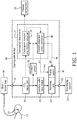
- an illustrative capnograph device 10 is diagrammatically shown.
- air flow pathways are indicated by solid lines connecting components along the air flow path, while electrical or electronic signals are indicated by dotted arrows.
- the illustrative capnograph device 10 is connected with a patient 12 by a suitable patient accessory (or sampling accessory), such as an illustrative nasal cannula 14 in the illustrative example, or by an airway adaptor or so forth.
- the patient accessory 14 may optionally include one or more ancillary components, such as an illustrative air filter/water trap assembly 16 (that is, the complete patient accessory 14 , 16 in the illustrative example includes the nasal cannula 14 and the connected filter/water trap assembly 16 ).
- Air is drawn from the patient accessory 14, 16 into the capnograph air inlet 18 by a pumping unit 20 , and the air is discharged from an air outlet 22 of the capnograph 10 to atmosphere or, as in the illustrative embodiment, into a scavenging system 24 to remove any inhaled anesthetic or other inhaled medicinal agent.
- the illustrative capnograph device 10 includes a carbon dioxide (CO 2 ) measurement component or cell 28, for example an infrared optical absorption cell, through which respired air is drawn from the patient accessory 14, 16 via the inlet 18 for analysis.
- a pressure gauge 30 measures the pressure (e.g., gauge pressure) of air in the air flow path through the capnograph device 10.
- Capnograph electronics 32 implement a capnography data processing component 34 that samples the CO 2 signal from the CO 2 measurement cell 28 to generate a capnogram (that is, a data stream of CO 2 level samples versus time, normalized in accordance with a chosen scale, e.g. as a partial pressure of CO 2 scaled using the pressure provided by the pressure gauge 30.
- the capnography data processing component 34 typically also computes the end-tidal CO 2 level, e.g. expressed as a partial pressure (PetCO 2 ), which is defined as the maximum CO 2 level observed over a breath cycle.
- a capillary tube flow meter 36 or other flow meter provides further information for the CO 2 level data analysis (connection of the air flow signal from the flow meter 36 to the data processing component 34 is not shown in FIGURE 1 ).
- Clinical data output by the capnograph 10 such as the capnogram and the PetCO 2 value for each breath, are displayed on a display component 38, stored in an electronic medical record (EMR) or the like, or otherwise utilized.
- EMR electronic medical record
- the display component 38 may be a component of the capnograph or, as illustrated in FIGURE 1 , the display component 38 may be an external display component connected to the capnograph 10.
- the external display component 38 may be a multi-function bedside patient monitor and/or a nurses' station patient monitor or so forth.
- the pressure gauge 30 is a conventional component of a typical commercial capnograph device or other respiratory gas analyzer device, and is conventionally used to provide a pressure reading for air flow through the capnograph for use in assessing partial pressure values or other respiratory gas analysis functionality.
- the pressure gauge 30 is also suitably used to detect operational connection of the patient 12 to the inlet 18 of the capnograph device 10 so as to turn on the pump 20 only when a patient is in operational connection with the device 10.
- the capnograph electronics 32 are further programmed to implement a patient detection-based pump controller 40 that turns on the pump 20 in response to detecting operational connection of the patient 12 to the inlet 18 of the capnograph device 10 via the pressure gauge 30.
- a rapid change in this pressure is recognizes as indicating a reasonable likelihood that a patient has been operatively connected to the inlet 18.
- a pump switch 42 of the pumping unit 20 is activated (e.g.
- the patient detection-based pump controller 40 further performs a validation operation to validate that the detected pressure change is actually due to operational connection of a patient. This validation may be based on a detected rapid decrease in the pressure measured by the pressure gauge 30 upon the pump 20 being turned on. A rapid pressure decrease is indicative of the pump 20 drawing against a significant air flow resistance, such as is expected to be encountered when the air inlet 18 is operatively connected with the patient 12; in contrast to the air flow path being "open" because no patient accessory 14 , 16 is connected to the inlet 18, or alternatively the patient accessory 14,16 is connected but no patient is connected with the patient accessory 14, 16.
- Another suitable validation criterion is observation of a pressure waveform as a function of time that cycles in accord with natural breathing or a known mechanical ventilation mode.
- a secondary validation metric when the CO 2 measurement cell 28 readout is stable (usually a few seconds after pump turn on, e.g. 4 sec in some illustrative examples herein) the operational patient connection can be directly validated by detecting whether a physically reasonable CO 2 reading is obtained.
- the pump 20 is immediately turned off, e.g. by sending an "off' signal 46 to the pump switch 42.
- the pump 20 runs as per normal capnograph device operation until a pump turn off criterion is met (e.g. the pressure goes to zero, or the CO 2 level goes to zero, over some time interval), at which time the "off' signal 46 is sent to turn off the pump 20.
- the described pumping unit 20 with on/off switch 42 that is turned on by a designated “on” signal 44 or off by a designated “off' signal 46 is merely an illustrative example, and that numerous other pump operation configurations can be employed.
- the capnograph electronics maybe configured to send a power signal to the pumping unit which powers the pump, in which case the patient detection-based pump controller 40 applies the pump power signal to turn the pump on (i.e. to operate the pump) and removes the pump power signal to turn the pump off.
- the on/off switch 42 may be omitted.
- capnograph electronics 32 may be variously implemented, such as by a suitably programmed electronic processor, e.g. a microprocessor or microcontroller of the capnograph 10. While a single electronics unit 32 is illustrated, it is alternatively contemplated to employ various combinations of electronics, for example the CO 2 data processing component 34 may be implemented by a first microprocessor or microcontroller while the patient detection-based pump controller 40 may be implemented by a separate second microprocessor or microcontroller. In such embodiments, the second microprocessor or microcontroller may optionally be built into the pump itself.
- the patient detection-based pump control functionality may be embodied by a non-transitory storage medium storing instructions that are readable and executable by the microprocessor, microcontroller, or other electronic processor to perform the patient detection-based pump control as disclosed herein.
- non-transitory storage media may, by way of non-limiting illustration, include a hard disk drive or other magnetic storage medium, a flash memory, read-only memory (ROM) or other electronic storage medium, an optical disk or other optical storage medium, various combinations thereof, or so forth.
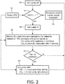
- the process starts with the pump 20 turned off in a starting state 50.
- the input for the patient detection includes the pressure 52 from the pressure gauge 50.
- the measured pressure as a function of time is denoted herein as P( t ) where t denotes time.
- the pressure 52 is monitored to detect a change in pressure, denoted herein as ⁇ P , that is greater than a pressure change threshold 56, denoted herein as T .
- the operation 54 detects the patient operational connection condition
- the pre-selected time interval over which the pressure change ⁇ P is measured may also be a parameter - since the expectation is that patient connection will produce an abrupt change in the measured pressure 52, this pre-selected time interval is preferably short, in some embodiments on the order of 1-2 seconds or shorter.
- the pressure change threshold 56 may be a configurable parameter of the capnograph 10. For example, the threshold 56 may be smaller for an elderly or infant patient, or may be higher for a patient receiving strong mechanical ventilation.
- the length of the patient accessory 14, 16 or the presence/absence of flow impedance-adding intervening components such as the illustrative filter/trap 16 may also impact the optimal value for the threshold 56. It is also contemplated to configure the threshold 56 based on the criticality of achieving rapid capnograph measurement. For example, a capnograph device being used in a doctor's office may be preferably set with a high threshold (and thus is slower to turn on which extends pump operational life) as compared with a capnograph device used in a critical care unit where the threshold 56 is set to a low value (potentially reduced pump life is beneficially sacrificed here to ensure rapid CO 2 measurement for a critically ill patient).
- the operation 54 may employ a pump turn on criterion other than the illustrative criterion
- the pump turn on criterion may be ⁇ P ( t ) > T.
- the pump turn on criterion may be based on detecting a breathing waveform, for example observing periodicity over a time interval encompassing several breaths that has an expected respiratory periodicity.
- the pump turn on criterion is an observable feature of the pressure P ( t ) 52 measured by the pressure gauge 30 that is characteristic of operative connection of the capnograph device 10 (and more particularly the inlet 18 ) to a patient who is being mechanically ventilated or breathing without assistance from a mechanical ventilator.
- the pump 20 When the patient connection condition
- the validation operation 60 advantageously leverages additional information that becomes available upon the pump 20 being turned on, or leverages other information. For example, in the case of connection to a patient who is breathing on his or her own, it is expected that the pressure 52 will decrease rapidly when the pump 20 is turned on because the pump draws against a relatively high flow impedance produced by the patient accessory 14,16 connected with the patient 12.
- this validation criterion may be expressed as - ⁇ P
- T val is a validation threshold which again may be a configurable parameter of the capnograph device 10, as the optimal threshold may depend on various factors such as the type of patient accessory (e.g. nasal cannula size, or airway adapter, et cetera), the pressure in the main airway, or so forth.
- Another suitable validation criterion is a metric of whether the pressure P ( t ) cycles over time with the expected patient breathing (under force of the patient's diaphragm or assisted or driven by mechanical ventilation).
- T breath > T val 2 maybe used, where T breath is chosen to be long enough to encompass at least one breath cycle (typically around least 3-6 seconds) and the difference P max - P min is the observed pressure variation over this time interval.
- a time-based criterion may be used, e.g. the time interval between consecutive pressure maxima or between consecutive pressure minima is expected to correspond to a single breath.
- the patient connection may be validated if the maximum pressure P max over a time interval is greater than some threshold.
- This validation criterion may be particularly useful in the case of a mechanically ventilated patient with an airway adapter patient accessory, such that the full maximum pressure applied by the ventilator is observed by the capnograph device 10.
- the validation operation 60 may additionally or alternatively use the actual CO 2 reading (or other measured respired gas component) output by the CO 2 measurement cell 28 (or other gas measurement component) for validation of the pump start up. Typically, it takes a few seconds (e.g. 4 seconds in some devices) for the CO 2 reading to stabilize. If a physically reasonable CO 2 value is measured by the measurement cell 28 after this stabilization interval, then patient connection is validated.
- a physically reasonable CO 2 value may, for example, be quantified as the end-tidal CO 2 level (conventionally denoted as etCO 2 and conventionally defined as the maximum CO 2 level observed during a breathing cycle) exceeding some minimum threshold T etCO 2 ; that is, the validation criterion is etCO 2 > T etCO 2 .
- T etCO 2 some minimum threshold
- a disadvantage of this approach is that there is the stabilization delay, but an advantage is that this validation directly operates on the CO 2 reading - that is, the pump turn on is validated if there is in fact an operation connection of the capnograph device 10 to a patient 12.
- This criterion will also ensure that the pump does not stay turned on if the CO 2 measurement component 28 is malfunctioning so as to output a false-low (e.g. zero) CO 2 level, even if the capnograph 10 is properly connected with the patient, thus ensuring the capnograph 10 does not run unnecessarily while generating bad CO 2 level data.
- an operation 62 it is determined from the output of the validation operation 60 whether or not the pump turn on is validated, that is, whether or not a patient is verified to be operationally connected to the capnograph 10. If only one patient connection validation criterion is employed then this determination is straightforward. If more than one patient connection validation criterion is employed then the outputs of the two or more criteria may be variously combined, e.g. validating patient connection if any one of the validation criteria is met; or alternatively, validating only if all of the patient validation criteria are met.
- a more reliable criterion may "override" a less reliable criterion - for example, if the CO 2 reading is reasonable (which is a direct indication that a patient is operatively connected) then the operation 62 may optionally conclude a patient is connected even if the pressure decrease upon pump turn on does not meet the threshold T val and/or the pressure waveform is not consistent with a typical respiratory cycle.
- operation 62 determines that patient connection is not validated, then flow returns to operation 50 which turns off the pump 20 after which the pump controller 40 returns to the monitoring operation 54.
- process control passes to an operation 64 which runs the pump 20 (i.e. keeps the pump 20 on) until a turn off criterion is met.
- a suitable turn-off criterion is the pressure decreasing to a value sufficiently close to zero, that is, P ( t ) ⁇ 0 over a certain time interval sufficient to avoid pump shutoff due to spurious pressure drops (e.g. an interval of a few seconds to a few tens of seconds to avoid turning off the pump during the inspiration phase of the breathing cycle).
- Another suitable turn-off criterion is the carbon dioxide measured by the CO 2 measurement cell 28 decreasing to a value sufficiently close to zero, that is, CO 2 ( t ) ⁇ 0 over a certain time interval sufficient to avoid pump shutoff due to spurious CO 2 reading drops (e.g. an interval of a few seconds to a few tens of seconds to avoid turning off the pump during the inspiration phase of the breathing cycle).
- CO 2 ( t ) ⁇ 0 e.g. an interval of a few seconds to a few tens of seconds to avoid turning off the pump during the inspiration phase of the breathing cycle.
- the disclosed patient detection-based pump controller 40 in combination with a patient accessory that has a mechanical or optical connection switch.
- the pump does not turn on unless both the patient detection as described with reference to FIGURE 2 is met and the appropriate mechanical or optical switch input is received from the patient accessory.
- an advantage of the disclosed capnograph device 10 is that it can be used in conjunction with patient accessories that have no such mechanical or optical switch included either with the patient accessory or with the inlet of the capnograph device.
- the pump control algorithm of FIGURE 2 may optionally employ turn on, turn off, and/or patient validation parameters (e.g. thresholds) that are configurable parameters of the capnograph device.
- patient validation parameters e.g. thresholds
- the user may input the patient type (e.g. neonate, mechanically ventilated, et cetera) and/or the patient accessory type (cannula, airway adapter) and the pump controller 40 then reads the appropriate thresholds for that type of patient/connection from a look-up table.
- the illustrative embodiment comprises a capnograph device 10. More generally, it will be appreciated that the disclosed patient detection-based pump control may be advantageously employed in conjunction with any type of respiratory gas analyzer device that employs a pump to draw respired gas into a gas measurement component for sampling.
- the gas measurement component may be a CO 2 measurement component 28 (as illustrated), or may be a gas measurement component for measuring a partial pressure or other metric of oxygen, various volatile organic compounds, or other respired gas components.
Landscapes
- Health & Medical Sciences (AREA)
- Life Sciences & Earth Sciences (AREA)
- Medical Informatics (AREA)
- Molecular Biology (AREA)
- Pulmonology (AREA)
- Biophysics (AREA)
- Pathology (AREA)
- Engineering & Computer Science (AREA)
- Biomedical Technology (AREA)
- Heart & Thoracic Surgery (AREA)
- Physiology (AREA)
- Physics & Mathematics (AREA)
- Surgery (AREA)
- Animal Behavior & Ethology (AREA)
- General Health & Medical Sciences (AREA)
- Public Health (AREA)
- Veterinary Medicine (AREA)
- Emergency Medicine (AREA)
- Obesity (AREA)
- Measurement Of The Respiration, Hearing Ability, Form, And Blood Characteristics Of Living Organisms (AREA)
- Investigating Or Analysing Biological Materials (AREA)
Claims (10)
- Dispositif d'analyse de gaz respiratoire (10), comprenant :- un élément de mesure de gaz (28) configuré pour mesurer au moins une composante de gaz respiré d'un patient ;- une pompe (20) raccordée pour aspirer le gaz respiré à travers l'élément de mesure de gaz ;- un manomètre (30) raccordé pour mesurer une pression dans un trajet d'écoulement d'air comprenant l'élément de mesure de gaz et la pompe ; et- une unité de commande de pompe électronique (40) programmée pour démarrer la pompe en réponse à une pression mesurée par le manomètre satisfaisant un critère d'allumage de pompe ;- dans lequel l'unité de commande de pompe électronique (40) est en outre programmée, après le démarrage de la pompe, pour valider le démarrage de la pompe par détermination du raccord ou non du patient au dispositif d'analyse de gaz respiratoire (10) sur la base (i) d'un critère de pression qui dépend de la pression mesurée par le manomètre et (ii) d'un critère de composante de gaz respiré qui dépend de la composante de gaz respiré mesurée émise par l'élément de mesure de gaz (28) ; et- pour arrêter la pompe (20) en cas d'échec de la validation,- et dans lequel l'élément de mesure de gaz (28) inclut un élément de mesure de dioxyde de carbone (28) et la composante de gaz respiré mesurée inclut une mesure de dioxyde de carbone ; et- le critère de composante de gaz respiré inclut le dioxyde de carbone en fin d'expiration, etCO2, mesuré par l'élément de mesure de dioxyde de carbone excédant un seuil (TetCO2 ).
- Dispositif d'analyse de gaz respiratoire (10) selon la revendication 1, dans lequel l'unité de commande de pompe électronique (40) est programmée pour démarrer la pompe (20) en réponse à un changement abrupt de pression mesuré par le manomètre (30) d'une magnitude supérieure à un seuil de mise en marche de pompe.
- Dispositif d'analyse de gaz respiratoire (10) selon la revendication 2, dans lequel le changement abrupt de pression est mesuré sur un intervalle de temps présélectionné de 2 secondes ou moins.
- Dispositif d'analyse de gaz respiratoire (10) selon l'une quelconque des revendications 2-4 dans lequel l'unité de commande de pompe électronique (40) est programmée pour définir le seuil de mise en marche de pompe en réponse à une entrée utilisateur, en tant que paramètre configurable du dispositif d'analyse de gaz respiratoire (10) dont la valeur est configurée sur la base d'au moins un type de patient et un type d'accessoire patient.
- Dispositif d'analyse de gaz respiratoire selon l'une quelconque des revendications précédentes, comprenant un capnographe (10) dans lequel l'élément de mesure de gaz comprend un élément de mesure de dioxyde de carbone (28).
- Dispositif d'analyse de gaz respiratoire (10) selon l'une quelconque des revendications précédentes, dans lequel le critère de mise en marche de pompe est un changement de pression abrupt, mesuré par le manomètre (30) sur un intervalle de temps présélectionné de 2 secondes ou moins, d'une magnitude supérieure à un seuil de mise en marche de pompe.
- Dispositif d'analyse de gaz respiratoire (10) selon l'une quelconque des revendications précédentes, dans lequel le critère de mise en marche de pompe est une augmentation abrupte de la pression, mesurée par le manomètre (30) sur un intervalle de temps présélectionné de 2 secondes ou moins, supérieure à un seuil de mise en marche de pompe.
- Dispositif d'analyse de gaz respiratoire (10) selon l'une quelconque des revendications 1 à 5, dans lequel le critère de mise en marche de pompe est une périodicité détectée de pression mesurée par le manomètre (30).
- Dispositif d'analyse de gaz respiratoire selon l'une quelconque des revendications précédentes, dans lequel l'unité de commande de pompe électronique (40) est en outre programmée :après la validation de raccord patient (62), pour surveiller (64) au moins l'un de la pression mesurée par le manomètre (30) et du dioxyde de carbone dans le gaz respiré mesuré par l'élément de mesure de dioxyde de carbone (28) ; etpour arrêter la pompe (20) en réponse à la diminution de la pression ou du dioxyde de carbone contrôlé(e) au-dessous d'un seuil pendant un intervalle de temps présélectionné.
- Dispositif d'analyse de gaz respiratoire selon l'une quelconque des revendications précédentes, dans lequel l'unité de commande de pompe électronique (40) est programmée pour démarrer la pompe (20) par l'un de :(i) l'envoi d'un signal « marche » à un commutateur marche/arrêt (42) de la pompe et(ii) l'envoi d'un signal d'alimentation à la pompe pour faire fonctionner la pompe.
Applications Claiming Priority (2)
| Application Number | Priority Date | Filing Date | Title |
|---|---|---|---|
| US201562203413P | 2015-08-11 | 2015-08-11 | |
| PCT/EP2016/069183 WO2017025615A1 (fr) | 2015-08-11 | 2016-08-11 | Système d'accessoire d'échantillonnage automatique et procédé de détection |
Publications (2)
| Publication Number | Publication Date |
|---|---|
| EP3334341A1 EP3334341A1 (fr) | 2018-06-20 |
| EP3334341B1 true EP3334341B1 (fr) | 2019-12-25 |
Family
ID=56842788
Family Applications (1)
| Application Number | Title | Priority Date | Filing Date |
|---|---|---|---|
| EP16757836.8A Active EP3334341B1 (fr) | 2015-08-11 | 2016-08-11 | Système d'accessoire d'échantillonnage automatique |
Country Status (5)
| Country | Link |
|---|---|
| US (1) | US11246506B2 (fr) |
| EP (1) | EP3334341B1 (fr) |
| JP (1) | JP6946264B2 (fr) |
| CN (1) | CN108024761B (fr) |
| WO (1) | WO2017025615A1 (fr) |
Families Citing this family (4)
| Publication number | Priority date | Publication date | Assignee | Title |
|---|---|---|---|---|
| CN112055560B (zh) * | 2018-04-30 | 2025-01-28 | 皇家飞利浦有限公司 | 二氧化碳描记模块中的附件检测 |
| WO2020258316A1 (fr) * | 2019-06-28 | 2020-12-30 | 深圳迈瑞生物医疗电子股份有限公司 | Procédé et appareil de mesure de gaz, dispositif de ventilation et support de stockage |
| US12364411B2 (en) | 2020-04-03 | 2025-07-22 | Zeteo Tech, Inc. | Diagnosis of respiratory diseases using analysis of exhaled breath and aerosols |
| EP4312749A4 (fr) | 2021-03-31 | 2025-07-09 | Zeteo Tech Inc | Diagnostic de maladies respiratoires par capture de particules de biomatériau en aérosol à l'aide de systèmes et de procédés à lit fixe |
Family Cites Families (18)
| Publication number | Priority date | Publication date | Assignee | Title |
|---|---|---|---|---|
| FR2517961A1 (fr) * | 1981-12-11 | 1983-06-17 | Synthelabo Biomedical | Procede et dispositif pour commander la respiration artificielle |
| US4958075A (en) * | 1987-10-09 | 1990-09-18 | Ntc Technology Inc. | Gas analyzer |
| US5386833A (en) * | 1993-12-23 | 1995-02-07 | Biochem International, Inc. | Method for calibrating a carbon dioxide monitor |
| WO2003105720A2 (fr) * | 2002-06-01 | 2003-12-24 | Oded Luria | Trousse medicale de secours, pompe respiratoire, et masque facial particulierement utile |
| US20060178592A1 (en) * | 2005-02-07 | 2006-08-10 | Aperson Biosystems Corp. | System and method for controlling the flow of exhaled breath during analysis |
| WO2007059263A2 (fr) * | 2005-11-16 | 2007-05-24 | Cardiopulmonary Technologies, Inc, | Systeme et procede de surveillance de gaz respiratoire secondaire |
| US7810497B2 (en) * | 2006-03-20 | 2010-10-12 | Ric Investments, Llc | Ventilatory control system |
| WO2009053958A1 (fr) * | 2007-10-25 | 2009-04-30 | Oridion Medical (1987) Ltd. | Système d'échantillonnage de gaz respiratoire |
| US8230858B2 (en) * | 2008-04-01 | 2012-07-31 | General Electric Company | Controlling the operation of a respiratory gas monitor |
| JP5570853B2 (ja) * | 2010-02-26 | 2014-08-13 | 日本光電工業株式会社 | 人工呼吸装置 |
| US9907511B2 (en) | 2010-12-17 | 2018-03-06 | Koninklijke Philips N.V. | System and method of identifying breaths based solely on capnographic information |
| JP2014518725A (ja) * | 2011-05-23 | 2014-08-07 | ゾール メディカル コーポレイション | 換気品質フィードバックユニットを備えた医療用換気システム |
| CA2840209A1 (fr) * | 2011-06-28 | 2013-01-03 | Fred Hutchinson Cancer Research Center | Appareil de surveillance des gaz en fin d'expiration |
| US20130006134A1 (en) * | 2011-06-30 | 2013-01-03 | Nellcor Puritan Bennett Llc | Methods and systems for monitoring volumetric carbon dioxide |
| JP4997350B1 (ja) * | 2012-01-30 | 2012-08-08 | 東海電子株式会社 | 呼気中アルコール測定装置 |
| US9027552B2 (en) * | 2012-07-31 | 2015-05-12 | Covidien Lp | Ventilator-initiated prompt or setting regarding detection of asynchrony during ventilation |
| DE102012024672A1 (de) * | 2012-12-18 | 2014-06-18 | Dräger Medical GmbH | Beatmungsgerät und Verfahren zum Betrieb eines Beatmungsgerätes |
| US10499819B2 (en) * | 2013-01-08 | 2019-12-10 | Capnia, Inc. | Breath selection for analysis |
-
2016
- 2016-08-11 EP EP16757836.8A patent/EP3334341B1/fr active Active
- 2016-08-11 US US15/751,306 patent/US11246506B2/en active Active
- 2016-08-11 WO PCT/EP2016/069183 patent/WO2017025615A1/fr not_active Ceased
- 2016-08-11 JP JP2018506595A patent/JP6946264B2/ja active Active
- 2016-08-11 CN CN201680052371.1A patent/CN108024761B/zh active Active
Non-Patent Citations (1)
| Title |
|---|
| None * |
Also Published As
| Publication number | Publication date |
|---|---|
| JP2018530366A (ja) | 2018-10-18 |
| JP6946264B2 (ja) | 2021-10-06 |
| EP3334341A1 (fr) | 2018-06-20 |
| US11246506B2 (en) | 2022-02-15 |
| CN108024761A (zh) | 2018-05-11 |
| WO2017025615A1 (fr) | 2017-02-16 |
| CN108024761B (zh) | 2021-09-14 |
| US20180235512A1 (en) | 2018-08-23 |
Similar Documents
| Publication | Publication Date | Title |
|---|---|---|
| US20250025657A1 (en) | Assistive capnography device | |
| US6828910B2 (en) | Apparatus for monitoring gas concentrations | |
| JP3322902B2 (ja) | 携帯用二酸化炭素モニタ | |
| US7918226B2 (en) | Method and system for detecting breathing tube occlusion | |
| US8230858B2 (en) | Controlling the operation of a respiratory gas monitor | |
| US10010691B2 (en) | Breathing apparatus and method for detecting leakage in a sampling line | |
| EP3334341B1 (fr) | Système d'accessoire d'échantillonnage automatique | |
| EP3334340B1 (fr) | Dispositif d'affichage simplifié de co2 en fin d'expiration | |
| JP6665179B2 (ja) | 被験者の健康状態を決定する方法及びデバイス | |
| US9931054B2 (en) | Low dead space liquid trap | |
| JP5997175B2 (ja) | カプノグラフ情報だけに基づいて呼吸を識別するシステム及び方法 | |
| WO2018130673A1 (fr) | Système d'aide à la décision de surveillance physiologique combinant la capnométrie et la saturation en oxygène | |
| EP3334339B1 (fr) | Capnographie avec architecture de système de support de décision | |
| US11389607B2 (en) | Ventilation apparatus for cardiopulmonary resuscitation with display of the trend in CO2 | |
| CN102245099B (zh) | 确定受试者的功能残气量 | |
| EP1964514B1 (fr) | Contrôle d'exploitation d'un moniteur d'apnée à gaz | |
| US12064231B2 (en) | Accessory detection in capnography modules | |
| RU2790925C2 (ru) | Обнаружение принадлежности в капнографических модулях |
Legal Events
| Date | Code | Title | Description |
|---|---|---|---|
| STAA | Information on the status of an ep patent application or granted ep patent |
Free format text: STATUS: THE INTERNATIONAL PUBLICATION HAS BEEN MADE |
|
| PUAI | Public reference made under article 153(3) epc to a published international application that has entered the european phase |
Free format text: ORIGINAL CODE: 0009012 |
|
| STAA | Information on the status of an ep patent application or granted ep patent |
Free format text: STATUS: REQUEST FOR EXAMINATION WAS MADE |
|
| 17P | Request for examination filed |
Effective date: 20180312 |
|
| AK | Designated contracting states |
Kind code of ref document: A1 Designated state(s): AL AT BE BG CH CY CZ DE DK EE ES FI FR GB GR HR HU IE IS IT LI LT LU LV MC MK MT NL NO PL PT RO RS SE SI SK SM TR |
|
| AX | Request for extension of the european patent |
Extension state: BA ME |
|
| DAV | Request for validation of the european patent (deleted) | ||
| DAX | Request for extension of the european patent (deleted) | ||
| STAA | Information on the status of an ep patent application or granted ep patent |
Free format text: STATUS: EXAMINATION IS IN PROGRESS |
|
| 17Q | First examination report despatched |
Effective date: 20190311 |
|
| GRAP | Despatch of communication of intention to grant a patent |
Free format text: ORIGINAL CODE: EPIDOSNIGR1 |
|
| STAA | Information on the status of an ep patent application or granted ep patent |
Free format text: STATUS: GRANT OF PATENT IS INTENDED |
|
| INTG | Intention to grant announced |
Effective date: 20190717 |
|
| GRAS | Grant fee paid |
Free format text: ORIGINAL CODE: EPIDOSNIGR3 |
|
| GRAA | (expected) grant |
Free format text: ORIGINAL CODE: 0009210 |
|
| STAA | Information on the status of an ep patent application or granted ep patent |
Free format text: STATUS: THE PATENT HAS BEEN GRANTED |
|
| AK | Designated contracting states |
Kind code of ref document: B1 Designated state(s): AL AT BE BG CH CY CZ DE DK EE ES FI FR GB GR HR HU IE IS IT LI LT LU LV MC MK MT NL NO PL PT RO RS SE SI SK SM TR |
|
| REG | Reference to a national code |
Ref country code: GB Ref legal event code: FG4D |
|
| REG | Reference to a national code |
Ref country code: CH Ref legal event code: EP |
|
| REG | Reference to a national code |
Ref country code: AT Ref legal event code: REF Ref document number: 1216221 Country of ref document: AT Kind code of ref document: T Effective date: 20200115 |
|
| REG | Reference to a national code |
Ref country code: DE Ref legal event code: R096 Ref document number: 602016026889 Country of ref document: DE |
|
| REG | Reference to a national code |
Ref country code: IE Ref legal event code: FG4D |
|
| RAP2 | Party data changed (patent owner data changed or rights of a patent transferred) |
Owner name: KONINKLIJKE PHILIPS N.V. |
|
| REG | Reference to a national code |
Ref country code: NL Ref legal event code: MP Effective date: 20191225 |
|
| PG25 | Lapsed in a contracting state [announced via postgrant information from national office to epo] |
Ref country code: GR Free format text: LAPSE BECAUSE OF FAILURE TO SUBMIT A TRANSLATION OF THE DESCRIPTION OR TO PAY THE FEE WITHIN THE PRESCRIBED TIME-LIMIT Effective date: 20200326 Ref country code: SE Free format text: LAPSE BECAUSE OF FAILURE TO SUBMIT A TRANSLATION OF THE DESCRIPTION OR TO PAY THE FEE WITHIN THE PRESCRIBED TIME-LIMIT Effective date: 20191225 Ref country code: NO Free format text: LAPSE BECAUSE OF FAILURE TO SUBMIT A TRANSLATION OF THE DESCRIPTION OR TO PAY THE FEE WITHIN THE PRESCRIBED TIME-LIMIT Effective date: 20200325 Ref country code: LV Free format text: LAPSE BECAUSE OF FAILURE TO SUBMIT A TRANSLATION OF THE DESCRIPTION OR TO PAY THE FEE WITHIN THE PRESCRIBED TIME-LIMIT Effective date: 20191225 Ref country code: FI Free format text: LAPSE BECAUSE OF FAILURE TO SUBMIT A TRANSLATION OF THE DESCRIPTION OR TO PAY THE FEE WITHIN THE PRESCRIBED TIME-LIMIT Effective date: 20191225 Ref country code: BG Free format text: LAPSE BECAUSE OF FAILURE TO SUBMIT A TRANSLATION OF THE DESCRIPTION OR TO PAY THE FEE WITHIN THE PRESCRIBED TIME-LIMIT Effective date: 20200325 Ref country code: LT Free format text: LAPSE BECAUSE OF FAILURE TO SUBMIT A TRANSLATION OF THE DESCRIPTION OR TO PAY THE FEE WITHIN THE PRESCRIBED TIME-LIMIT Effective date: 20191225 |
|
| REG | Reference to a national code |
Ref country code: LT Ref legal event code: MG4D |
|
| PG25 | Lapsed in a contracting state [announced via postgrant information from national office to epo] |
Ref country code: HR Free format text: LAPSE BECAUSE OF FAILURE TO SUBMIT A TRANSLATION OF THE DESCRIPTION OR TO PAY THE FEE WITHIN THE PRESCRIBED TIME-LIMIT Effective date: 20191225 Ref country code: RS Free format text: LAPSE BECAUSE OF FAILURE TO SUBMIT A TRANSLATION OF THE DESCRIPTION OR TO PAY THE FEE WITHIN THE PRESCRIBED TIME-LIMIT Effective date: 20191225 |
|
| PG25 | Lapsed in a contracting state [announced via postgrant information from national office to epo] |
Ref country code: AL Free format text: LAPSE BECAUSE OF FAILURE TO SUBMIT A TRANSLATION OF THE DESCRIPTION OR TO PAY THE FEE WITHIN THE PRESCRIBED TIME-LIMIT Effective date: 20191225 |
|
| PG25 | Lapsed in a contracting state [announced via postgrant information from national office to epo] |
Ref country code: CZ Free format text: LAPSE BECAUSE OF FAILURE TO SUBMIT A TRANSLATION OF THE DESCRIPTION OR TO PAY THE FEE WITHIN THE PRESCRIBED TIME-LIMIT Effective date: 20191225 Ref country code: RO Free format text: LAPSE BECAUSE OF FAILURE TO SUBMIT A TRANSLATION OF THE DESCRIPTION OR TO PAY THE FEE WITHIN THE PRESCRIBED TIME-LIMIT Effective date: 20191225 Ref country code: NL Free format text: LAPSE BECAUSE OF FAILURE TO SUBMIT A TRANSLATION OF THE DESCRIPTION OR TO PAY THE FEE WITHIN THE PRESCRIBED TIME-LIMIT Effective date: 20191225 Ref country code: PT Free format text: LAPSE BECAUSE OF FAILURE TO SUBMIT A TRANSLATION OF THE DESCRIPTION OR TO PAY THE FEE WITHIN THE PRESCRIBED TIME-LIMIT Effective date: 20200520 Ref country code: EE Free format text: LAPSE BECAUSE OF FAILURE TO SUBMIT A TRANSLATION OF THE DESCRIPTION OR TO PAY THE FEE WITHIN THE PRESCRIBED TIME-LIMIT Effective date: 20191225 |
|
| PG25 | Lapsed in a contracting state [announced via postgrant information from national office to epo] |
Ref country code: SM Free format text: LAPSE BECAUSE OF FAILURE TO SUBMIT A TRANSLATION OF THE DESCRIPTION OR TO PAY THE FEE WITHIN THE PRESCRIBED TIME-LIMIT Effective date: 20191225 Ref country code: SK Free format text: LAPSE BECAUSE OF FAILURE TO SUBMIT A TRANSLATION OF THE DESCRIPTION OR TO PAY THE FEE WITHIN THE PRESCRIBED TIME-LIMIT Effective date: 20191225 Ref country code: IS Free format text: LAPSE BECAUSE OF FAILURE TO SUBMIT A TRANSLATION OF THE DESCRIPTION OR TO PAY THE FEE WITHIN THE PRESCRIBED TIME-LIMIT Effective date: 20200425 |
|
| REG | Reference to a national code |
Ref country code: DE Ref legal event code: R097 Ref document number: 602016026889 Country of ref document: DE |
|
| PG25 | Lapsed in a contracting state [announced via postgrant information from national office to epo] |
Ref country code: DK Free format text: LAPSE BECAUSE OF FAILURE TO SUBMIT A TRANSLATION OF THE DESCRIPTION OR TO PAY THE FEE WITHIN THE PRESCRIBED TIME-LIMIT Effective date: 20191225 Ref country code: ES Free format text: LAPSE BECAUSE OF FAILURE TO SUBMIT A TRANSLATION OF THE DESCRIPTION OR TO PAY THE FEE WITHIN THE PRESCRIBED TIME-LIMIT Effective date: 20191225 |
|
| PLBE | No opposition filed within time limit |
Free format text: ORIGINAL CODE: 0009261 |
|
| STAA | Information on the status of an ep patent application or granted ep patent |
Free format text: STATUS: NO OPPOSITION FILED WITHIN TIME LIMIT |
|
| REG | Reference to a national code |
Ref country code: AT Ref legal event code: MK05 Ref document number: 1216221 Country of ref document: AT Kind code of ref document: T Effective date: 20191225 |
|
| PG25 | Lapsed in a contracting state [announced via postgrant information from national office to epo] |
Ref country code: SI Free format text: LAPSE BECAUSE OF FAILURE TO SUBMIT A TRANSLATION OF THE DESCRIPTION OR TO PAY THE FEE WITHIN THE PRESCRIBED TIME-LIMIT Effective date: 20191225 |
|
| 26N | No opposition filed |
Effective date: 20200928 |
|
| PG25 | Lapsed in a contracting state [announced via postgrant information from national office to epo] |
Ref country code: IT Free format text: LAPSE BECAUSE OF FAILURE TO SUBMIT A TRANSLATION OF THE DESCRIPTION OR TO PAY THE FEE WITHIN THE PRESCRIBED TIME-LIMIT Effective date: 20191225 Ref country code: AT Free format text: LAPSE BECAUSE OF FAILURE TO SUBMIT A TRANSLATION OF THE DESCRIPTION OR TO PAY THE FEE WITHIN THE PRESCRIBED TIME-LIMIT Effective date: 20191225 |
|
| PG25 | Lapsed in a contracting state [announced via postgrant information from national office to epo] |
Ref country code: PL Free format text: LAPSE BECAUSE OF FAILURE TO SUBMIT A TRANSLATION OF THE DESCRIPTION OR TO PAY THE FEE WITHIN THE PRESCRIBED TIME-LIMIT Effective date: 20191225 |
|
| PG25 | Lapsed in a contracting state [announced via postgrant information from national office to epo] |
Ref country code: MC Free format text: LAPSE BECAUSE OF FAILURE TO SUBMIT A TRANSLATION OF THE DESCRIPTION OR TO PAY THE FEE WITHIN THE PRESCRIBED TIME-LIMIT Effective date: 20191225 |
|
| REG | Reference to a national code |
Ref country code: CH Ref legal event code: PL |
|
| PG25 | Lapsed in a contracting state [announced via postgrant information from national office to epo] |
Ref country code: LI Free format text: LAPSE BECAUSE OF NON-PAYMENT OF DUE FEES Effective date: 20200831 Ref country code: LU Free format text: LAPSE BECAUSE OF NON-PAYMENT OF DUE FEES Effective date: 20200811 Ref country code: CH Free format text: LAPSE BECAUSE OF NON-PAYMENT OF DUE FEES Effective date: 20200831 |
|
| REG | Reference to a national code |
Ref country code: BE Ref legal event code: MM Effective date: 20200831 |
|
| PG25 | Lapsed in a contracting state [announced via postgrant information from national office to epo] |
Ref country code: IE Free format text: LAPSE BECAUSE OF NON-PAYMENT OF DUE FEES Effective date: 20200811 Ref country code: BE Free format text: LAPSE BECAUSE OF NON-PAYMENT OF DUE FEES Effective date: 20200831 |
|
| PG25 | Lapsed in a contracting state [announced via postgrant information from national office to epo] |
Ref country code: TR Free format text: LAPSE BECAUSE OF FAILURE TO SUBMIT A TRANSLATION OF THE DESCRIPTION OR TO PAY THE FEE WITHIN THE PRESCRIBED TIME-LIMIT Effective date: 20191225 Ref country code: MT Free format text: LAPSE BECAUSE OF FAILURE TO SUBMIT A TRANSLATION OF THE DESCRIPTION OR TO PAY THE FEE WITHIN THE PRESCRIBED TIME-LIMIT Effective date: 20191225 Ref country code: CY Free format text: LAPSE BECAUSE OF FAILURE TO SUBMIT A TRANSLATION OF THE DESCRIPTION OR TO PAY THE FEE WITHIN THE PRESCRIBED TIME-LIMIT Effective date: 20191225 |
|
| PG25 | Lapsed in a contracting state [announced via postgrant information from national office to epo] |
Ref country code: MK Free format text: LAPSE BECAUSE OF FAILURE TO SUBMIT A TRANSLATION OF THE DESCRIPTION OR TO PAY THE FEE WITHIN THE PRESCRIBED TIME-LIMIT Effective date: 20191225 |
|
| REG | Reference to a national code |
Ref country code: DE Ref legal event code: R084 Ref document number: 602016026889 Country of ref document: DE |
|
| REG | Reference to a national code |
Ref country code: GB Ref legal event code: 746 Effective date: 20241217 |
|
| PGFP | Annual fee paid to national office [announced via postgrant information from national office to epo] |
Ref country code: DE Payment date: 20250827 Year of fee payment: 10 |
|
| PGFP | Annual fee paid to national office [announced via postgrant information from national office to epo] |
Ref country code: GB Payment date: 20250826 Year of fee payment: 10 |
|
| PGFP | Annual fee paid to national office [announced via postgrant information from national office to epo] |
Ref country code: FR Payment date: 20250825 Year of fee payment: 10 |