EP3334619B1 - Système de freinage et procédé pour véhicule électrique à quatre roues motrices et véhicule électrique - Google Patents
Système de freinage et procédé pour véhicule électrique à quatre roues motrices et véhicule électrique Download PDFInfo
- Publication number
- EP3334619B1 EP3334619B1 EP16834665.8A EP16834665A EP3334619B1 EP 3334619 B1 EP3334619 B1 EP 3334619B1 EP 16834665 A EP16834665 A EP 16834665A EP 3334619 B1 EP3334619 B1 EP 3334619B1
- Authority
- EP
- European Patent Office
- Prior art keywords
- brake
- electric vehicle
- value
- motor
- preset
- Prior art date
- Legal status (The legal status is an assumption and is not a legal conclusion. Google has not performed a legal analysis and makes no representation as to the accuracy of the status listed.)
- Active
Links
Images
Classifications
-
- B—PERFORMING OPERATIONS; TRANSPORTING
- B60—VEHICLES IN GENERAL
- B60L—PROPULSION OF ELECTRICALLY-PROPELLED VEHICLES; SUPPLYING ELECTRIC POWER FOR AUXILIARY EQUIPMENT OF ELECTRICALLY-PROPELLED VEHICLES; ELECTRODYNAMIC BRAKE SYSTEMS FOR VEHICLES IN GENERAL; MAGNETIC SUSPENSION OR LEVITATION FOR VEHICLES; MONITORING OPERATING VARIABLES OF ELECTRICALLY-PROPELLED VEHICLES; ELECTRIC SAFETY DEVICES FOR ELECTRICALLY-PROPELLED VEHICLES
- B60L3/00—Electric devices on electrically-propelled vehicles for safety purposes; Monitoring operating variables, e.g. speed, deceleration or energy consumption
- B60L3/0023—Detecting, eliminating, remedying or compensating for drive train abnormalities, e.g. failures within the drive train
- B60L3/0076—Detecting, eliminating, remedying or compensating for drive train abnormalities, e.g. failures within the drive train relating to braking
-
- B—PERFORMING OPERATIONS; TRANSPORTING
- B60—VEHICLES IN GENERAL
- B60L—PROPULSION OF ELECTRICALLY-PROPELLED VEHICLES; SUPPLYING ELECTRIC POWER FOR AUXILIARY EQUIPMENT OF ELECTRICALLY-PROPELLED VEHICLES; ELECTRODYNAMIC BRAKE SYSTEMS FOR VEHICLES IN GENERAL; MAGNETIC SUSPENSION OR LEVITATION FOR VEHICLES; MONITORING OPERATING VARIABLES OF ELECTRICALLY-PROPELLED VEHICLES; ELECTRIC SAFETY DEVICES FOR ELECTRICALLY-PROPELLED VEHICLES
- B60L15/00—Methods, circuits, or devices for controlling the traction-motor speed of electrically-propelled vehicles
- B60L15/20—Methods, circuits, or devices for controlling the traction-motor speed of electrically-propelled vehicles for control of the vehicle or its driving motor to achieve a desired performance, e.g. speed, torque, programmed variation of speed
- B60L15/2009—Methods, circuits, or devices for controlling the traction-motor speed of electrically-propelled vehicles for control of the vehicle or its driving motor to achieve a desired performance, e.g. speed, torque, programmed variation of speed for braking
-
- B—PERFORMING OPERATIONS; TRANSPORTING
- B60—VEHICLES IN GENERAL
- B60L—PROPULSION OF ELECTRICALLY-PROPELLED VEHICLES; SUPPLYING ELECTRIC POWER FOR AUXILIARY EQUIPMENT OF ELECTRICALLY-PROPELLED VEHICLES; ELECTRODYNAMIC BRAKE SYSTEMS FOR VEHICLES IN GENERAL; MAGNETIC SUSPENSION OR LEVITATION FOR VEHICLES; MONITORING OPERATING VARIABLES OF ELECTRICALLY-PROPELLED VEHICLES; ELECTRIC SAFETY DEVICES FOR ELECTRICALLY-PROPELLED VEHICLES
- B60L58/00—Methods or circuit arrangements for monitoring or controlling batteries or fuel cells, specially adapted for electric vehicles
- B60L58/10—Methods or circuit arrangements for monitoring or controlling batteries or fuel cells, specially adapted for electric vehicles for monitoring or controlling batteries
- B60L58/12—Methods or circuit arrangements for monitoring or controlling batteries or fuel cells, specially adapted for electric vehicles for monitoring or controlling batteries responding to state of charge [SoC]
- B60L58/13—Maintaining the SoC within a determined range
-
- B—PERFORMING OPERATIONS; TRANSPORTING
- B60—VEHICLES IN GENERAL
- B60L—PROPULSION OF ELECTRICALLY-PROPELLED VEHICLES; SUPPLYING ELECTRIC POWER FOR AUXILIARY EQUIPMENT OF ELECTRICALLY-PROPELLED VEHICLES; ELECTRODYNAMIC BRAKE SYSTEMS FOR VEHICLES IN GENERAL; MAGNETIC SUSPENSION OR LEVITATION FOR VEHICLES; MONITORING OPERATING VARIABLES OF ELECTRICALLY-PROPELLED VEHICLES; ELECTRIC SAFETY DEVICES FOR ELECTRICALLY-PROPELLED VEHICLES
- B60L7/00—Electrodynamic brake systems for vehicles in general
- B60L7/10—Dynamic electric regenerative braking
- B60L7/18—Controlling the braking effect
-
- B—PERFORMING OPERATIONS; TRANSPORTING
- B60—VEHICLES IN GENERAL
- B60L—PROPULSION OF ELECTRICALLY-PROPELLED VEHICLES; SUPPLYING ELECTRIC POWER FOR AUXILIARY EQUIPMENT OF ELECTRICALLY-PROPELLED VEHICLES; ELECTRODYNAMIC BRAKE SYSTEMS FOR VEHICLES IN GENERAL; MAGNETIC SUSPENSION OR LEVITATION FOR VEHICLES; MONITORING OPERATING VARIABLES OF ELECTRICALLY-PROPELLED VEHICLES; ELECTRIC SAFETY DEVICES FOR ELECTRICALLY-PROPELLED VEHICLES
- B60L7/00—Electrodynamic brake systems for vehicles in general
- B60L7/24—Electrodynamic brake systems for vehicles in general with additional mechanical or electromagnetic braking
- B60L7/26—Controlling the braking effect
-
- B—PERFORMING OPERATIONS; TRANSPORTING
- B60—VEHICLES IN GENERAL
- B60T—VEHICLE BRAKE CONTROL SYSTEMS OR PARTS THEREOF; BRAKE CONTROL SYSTEMS OR PARTS THEREOF, IN GENERAL; ARRANGEMENT OF BRAKING ELEMENTS ON VEHICLES IN GENERAL; PORTABLE DEVICES FOR PREVENTING UNWANTED MOVEMENT OF VEHICLES; VEHICLE MODIFICATIONS TO FACILITATE COOLING OF BRAKES
- B60T13/00—Transmitting braking action from initiating means to ultimate brake actuator with power assistance or drive; Brake systems incorporating such transmitting means, e.g. air-pressure brake systems
- B60T13/74—Transmitting braking action from initiating means to ultimate brake actuator with power assistance or drive; Brake systems incorporating such transmitting means, e.g. air-pressure brake systems with electrical assistance or drive
- B60T13/741—Transmitting braking action from initiating means to ultimate brake actuator with power assistance or drive; Brake systems incorporating such transmitting means, e.g. air-pressure brake systems with electrical assistance or drive acting on an ultimate actuator
-
- B—PERFORMING OPERATIONS; TRANSPORTING
- B60—VEHICLES IN GENERAL
- B60T—VEHICLE BRAKE CONTROL SYSTEMS OR PARTS THEREOF; BRAKE CONTROL SYSTEMS OR PARTS THEREOF, IN GENERAL; ARRANGEMENT OF BRAKING ELEMENTS ON VEHICLES IN GENERAL; PORTABLE DEVICES FOR PREVENTING UNWANTED MOVEMENT OF VEHICLES; VEHICLE MODIFICATIONS TO FACILITATE COOLING OF BRAKES
- B60T7/00—Brake-action initiating means
- B60T7/02—Brake-action initiating means for personal initiation
- B60T7/04—Brake-action initiating means for personal initiation foot actuated
- B60T7/042—Brake-action initiating means for personal initiation foot actuated by electrical means, e.g. using travel or force sensors
-
- B—PERFORMING OPERATIONS; TRANSPORTING
- B60—VEHICLES IN GENERAL
- B60T—VEHICLE BRAKE CONTROL SYSTEMS OR PARTS THEREOF; BRAKE CONTROL SYSTEMS OR PARTS THEREOF, IN GENERAL; ARRANGEMENT OF BRAKING ELEMENTS ON VEHICLES IN GENERAL; PORTABLE DEVICES FOR PREVENTING UNWANTED MOVEMENT OF VEHICLES; VEHICLE MODIFICATIONS TO FACILITATE COOLING OF BRAKES
- B60T8/00—Arrangements for adjusting wheel-braking force to meet varying vehicular or ground-surface conditions, e.g. limiting or varying distribution of braking force
- B60T8/17—Using electrical or electronic regulation means to control braking
- B60T8/171—Detecting parameters used in the regulation; Measuring values used in the regulation
-
- B—PERFORMING OPERATIONS; TRANSPORTING
- B60—VEHICLES IN GENERAL
- B60T—VEHICLE BRAKE CONTROL SYSTEMS OR PARTS THEREOF; BRAKE CONTROL SYSTEMS OR PARTS THEREOF, IN GENERAL; ARRANGEMENT OF BRAKING ELEMENTS ON VEHICLES IN GENERAL; PORTABLE DEVICES FOR PREVENTING UNWANTED MOVEMENT OF VEHICLES; VEHICLE MODIFICATIONS TO FACILITATE COOLING OF BRAKES
- B60T8/00—Arrangements for adjusting wheel-braking force to meet varying vehicular or ground-surface conditions, e.g. limiting or varying distribution of braking force
- B60T8/17—Using electrical or electronic regulation means to control braking
- B60T8/172—Determining control parameters used in the regulation, e.g. by calculations involving measured or detected parameters
-
- B—PERFORMING OPERATIONS; TRANSPORTING
- B60—VEHICLES IN GENERAL
- B60T—VEHICLE BRAKE CONTROL SYSTEMS OR PARTS THEREOF; BRAKE CONTROL SYSTEMS OR PARTS THEREOF, IN GENERAL; ARRANGEMENT OF BRAKING ELEMENTS ON VEHICLES IN GENERAL; PORTABLE DEVICES FOR PREVENTING UNWANTED MOVEMENT OF VEHICLES; VEHICLE MODIFICATIONS TO FACILITATE COOLING OF BRAKES
- B60T8/00—Arrangements for adjusting wheel-braking force to meet varying vehicular or ground-surface conditions, e.g. limiting or varying distribution of braking force
- B60T8/32—Arrangements for adjusting wheel-braking force to meet varying vehicular or ground-surface conditions, e.g. limiting or varying distribution of braking force responsive to a speed condition, e.g. acceleration or deceleration
- B60T8/72—Arrangements for adjusting wheel-braking force to meet varying vehicular or ground-surface conditions, e.g. limiting or varying distribution of braking force responsive to a speed condition, e.g. acceleration or deceleration responsive to a difference between a speed condition, e.g. deceleration, and a fixed reference
-
- B—PERFORMING OPERATIONS; TRANSPORTING
- B60—VEHICLES IN GENERAL
- B60L—PROPULSION OF ELECTRICALLY-PROPELLED VEHICLES; SUPPLYING ELECTRIC POWER FOR AUXILIARY EQUIPMENT OF ELECTRICALLY-PROPELLED VEHICLES; ELECTRODYNAMIC BRAKE SYSTEMS FOR VEHICLES IN GENERAL; MAGNETIC SUSPENSION OR LEVITATION FOR VEHICLES; MONITORING OPERATING VARIABLES OF ELECTRICALLY-PROPELLED VEHICLES; ELECTRIC SAFETY DEVICES FOR ELECTRICALLY-PROPELLED VEHICLES
- B60L2220/00—Electrical machine types; Structures or applications thereof
- B60L2220/40—Electrical machine applications
- B60L2220/46—Wheel motors, i.e. motor connected to only one wheel
-
- B—PERFORMING OPERATIONS; TRANSPORTING
- B60—VEHICLES IN GENERAL
- B60L—PROPULSION OF ELECTRICALLY-PROPELLED VEHICLES; SUPPLYING ELECTRIC POWER FOR AUXILIARY EQUIPMENT OF ELECTRICALLY-PROPELLED VEHICLES; ELECTRODYNAMIC BRAKE SYSTEMS FOR VEHICLES IN GENERAL; MAGNETIC SUSPENSION OR LEVITATION FOR VEHICLES; MONITORING OPERATING VARIABLES OF ELECTRICALLY-PROPELLED VEHICLES; ELECTRIC SAFETY DEVICES FOR ELECTRICALLY-PROPELLED VEHICLES
- B60L2240/00—Control parameters of input or output; Target parameters
- B60L2240/10—Vehicle control parameters
- B60L2240/12—Speed
-
- B—PERFORMING OPERATIONS; TRANSPORTING
- B60—VEHICLES IN GENERAL
- B60L—PROPULSION OF ELECTRICALLY-PROPELLED VEHICLES; SUPPLYING ELECTRIC POWER FOR AUXILIARY EQUIPMENT OF ELECTRICALLY-PROPELLED VEHICLES; ELECTRODYNAMIC BRAKE SYSTEMS FOR VEHICLES IN GENERAL; MAGNETIC SUSPENSION OR LEVITATION FOR VEHICLES; MONITORING OPERATING VARIABLES OF ELECTRICALLY-PROPELLED VEHICLES; ELECTRIC SAFETY DEVICES FOR ELECTRICALLY-PROPELLED VEHICLES
- B60L2240/00—Control parameters of input or output; Target parameters
- B60L2240/40—Drive Train control parameters
- B60L2240/42—Drive Train control parameters related to electric machines
- B60L2240/421—Speed
-
- B—PERFORMING OPERATIONS; TRANSPORTING
- B60—VEHICLES IN GENERAL
- B60L—PROPULSION OF ELECTRICALLY-PROPELLED VEHICLES; SUPPLYING ELECTRIC POWER FOR AUXILIARY EQUIPMENT OF ELECTRICALLY-PROPELLED VEHICLES; ELECTRODYNAMIC BRAKE SYSTEMS FOR VEHICLES IN GENERAL; MAGNETIC SUSPENSION OR LEVITATION FOR VEHICLES; MONITORING OPERATING VARIABLES OF ELECTRICALLY-PROPELLED VEHICLES; ELECTRIC SAFETY DEVICES FOR ELECTRICALLY-PROPELLED VEHICLES
- B60L2240/00—Control parameters of input or output; Target parameters
- B60L2240/40—Drive Train control parameters
- B60L2240/42—Drive Train control parameters related to electric machines
- B60L2240/423—Torque
-
- B—PERFORMING OPERATIONS; TRANSPORTING
- B60—VEHICLES IN GENERAL
- B60L—PROPULSION OF ELECTRICALLY-PROPELLED VEHICLES; SUPPLYING ELECTRIC POWER FOR AUXILIARY EQUIPMENT OF ELECTRICALLY-PROPELLED VEHICLES; ELECTRODYNAMIC BRAKE SYSTEMS FOR VEHICLES IN GENERAL; MAGNETIC SUSPENSION OR LEVITATION FOR VEHICLES; MONITORING OPERATING VARIABLES OF ELECTRICALLY-PROPELLED VEHICLES; ELECTRIC SAFETY DEVICES FOR ELECTRICALLY-PROPELLED VEHICLES
- B60L2250/00—Driver interactions
- B60L2250/26—Driver interactions by pedal actuation
-
- B—PERFORMING OPERATIONS; TRANSPORTING
- B60—VEHICLES IN GENERAL
- B60L—PROPULSION OF ELECTRICALLY-PROPELLED VEHICLES; SUPPLYING ELECTRIC POWER FOR AUXILIARY EQUIPMENT OF ELECTRICALLY-PROPELLED VEHICLES; ELECTRODYNAMIC BRAKE SYSTEMS FOR VEHICLES IN GENERAL; MAGNETIC SUSPENSION OR LEVITATION FOR VEHICLES; MONITORING OPERATING VARIABLES OF ELECTRICALLY-PROPELLED VEHICLES; ELECTRIC SAFETY DEVICES FOR ELECTRICALLY-PROPELLED VEHICLES
- B60L2260/00—Operating Modes
- B60L2260/20—Drive modes; Transition between modes
- B60L2260/28—Four wheel or all wheel drive
-
- B—PERFORMING OPERATIONS; TRANSPORTING
- B60—VEHICLES IN GENERAL
- B60T—VEHICLE BRAKE CONTROL SYSTEMS OR PARTS THEREOF; BRAKE CONTROL SYSTEMS OR PARTS THEREOF, IN GENERAL; ARRANGEMENT OF BRAKING ELEMENTS ON VEHICLES IN GENERAL; PORTABLE DEVICES FOR PREVENTING UNWANTED MOVEMENT OF VEHICLES; VEHICLE MODIFICATIONS TO FACILITATE COOLING OF BRAKES
- B60T2270/00—Further aspects of brake control systems not otherwise provided for
- B60T2270/40—Failsafe aspects of brake control systems
- B60T2270/402—Back-up
-
- B—PERFORMING OPERATIONS; TRANSPORTING
- B60—VEHICLES IN GENERAL
- B60T—VEHICLE BRAKE CONTROL SYSTEMS OR PARTS THEREOF; BRAKE CONTROL SYSTEMS OR PARTS THEREOF, IN GENERAL; ARRANGEMENT OF BRAKING ELEMENTS ON VEHICLES IN GENERAL; PORTABLE DEVICES FOR PREVENTING UNWANTED MOVEMENT OF VEHICLES; VEHICLE MODIFICATIONS TO FACILITATE COOLING OF BRAKES
- B60T2270/00—Further aspects of brake control systems not otherwise provided for
- B60T2270/60—Regenerative braking
- B60T2270/604—Merging friction therewith; Adjusting their repartition
-
- Y—GENERAL TAGGING OF NEW TECHNOLOGICAL DEVELOPMENTS; GENERAL TAGGING OF CROSS-SECTIONAL TECHNOLOGIES SPANNING OVER SEVERAL SECTIONS OF THE IPC; TECHNICAL SUBJECTS COVERED BY FORMER USPC CROSS-REFERENCE ART COLLECTIONS [XRACs] AND DIGESTS
- Y02—TECHNOLOGIES OR APPLICATIONS FOR MITIGATION OR ADAPTATION AGAINST CLIMATE CHANGE
- Y02T—CLIMATE CHANGE MITIGATION TECHNOLOGIES RELATED TO TRANSPORTATION
- Y02T10/00—Road transport of goods or passengers
- Y02T10/60—Other road transportation technologies with climate change mitigation effect
- Y02T10/64—Electric machine technologies in electromobility
-
- Y—GENERAL TAGGING OF NEW TECHNOLOGICAL DEVELOPMENTS; GENERAL TAGGING OF CROSS-SECTIONAL TECHNOLOGIES SPANNING OVER SEVERAL SECTIONS OF THE IPC; TECHNICAL SUBJECTS COVERED BY FORMER USPC CROSS-REFERENCE ART COLLECTIONS [XRACs] AND DIGESTS
- Y02—TECHNOLOGIES OR APPLICATIONS FOR MITIGATION OR ADAPTATION AGAINST CLIMATE CHANGE
- Y02T—CLIMATE CHANGE MITIGATION TECHNOLOGIES RELATED TO TRANSPORTATION
- Y02T10/00—Road transport of goods or passengers
- Y02T10/60—Other road transportation technologies with climate change mitigation effect
- Y02T10/70—Energy storage systems for electromobility, e.g. batteries
-
- Y—GENERAL TAGGING OF NEW TECHNOLOGICAL DEVELOPMENTS; GENERAL TAGGING OF CROSS-SECTIONAL TECHNOLOGIES SPANNING OVER SEVERAL SECTIONS OF THE IPC; TECHNICAL SUBJECTS COVERED BY FORMER USPC CROSS-REFERENCE ART COLLECTIONS [XRACs] AND DIGESTS
- Y02—TECHNOLOGIES OR APPLICATIONS FOR MITIGATION OR ADAPTATION AGAINST CLIMATE CHANGE
- Y02T—CLIMATE CHANGE MITIGATION TECHNOLOGIES RELATED TO TRANSPORTATION
- Y02T10/00—Road transport of goods or passengers
- Y02T10/60—Other road transportation technologies with climate change mitigation effect
- Y02T10/72—Electric energy management in electromobility
Definitions
- the present invention relates to the field of vehicles, and in particular, to a brake system for a four-wheel drive electric vehicle, a brake method for a four-wheel drive electric vehicle and a four-wheel drive electric vehicle.
- ABS anti-lock braking system
- ESP electronic stability program
- US 2010/076657 A1 discloses a brake system for a four-wheel drive electric vehicle, where it is chosen between frictional breaking and regenerative braking according to a state of charge (SOC) of a battery, according to a breaking force demand, and according to a vehicle speed.
- SOC state of charge
- CN 104 276 050 A discloses a brake control system, where the actual electric braking torque is determined and one or two motor generators are used to output a minimum feedback value.
- the present invention seeks to solve at least one of technical problems existing in the related art. To this end, the present invention provides a brake system for a four-wheel drive electric vehicle, a brake method for a four-wheel drive electric vehicle and a four-wheel drive electric vehicle.
- a brake system for a four-wheel drive electric vehicle is provided according to claim 1.
- a brake method for a four-wheel drive electric vehicle is provided according to claim 8.
- a four-wheel drive electric vehicle includes the brake system for a four-wheel drive electric vehicle described above; a battery pack; a motor; and a brake actuator, in which the battery pack, the motor and the brake actuator are connected with the brake system for a four-wheel drive electric vehicle respectively.
- first and second are used herein for purposes of description and are not intended to indicate or imply relative importance or significance or to imply the number of indicated technical features.
- the feature defined with “first” and “second” may include one or more of this feature.
- "a plurality of' means two or more than two, unless specified otherwise.
- the terms “mounted,” “connected,” and “coupled” should be understood broadly, for example, which may be fixed connections, detachable connections or integral connections; may be mechanical connections, electrical connections or mutual communication; may be direct connections, indirectly connected with each other through an intermediate medium, or communications inside two elements or an interaction relationship of two elements.
- the terms “mounted,” “connected,” and “coupled” should be understood broadly, for example, which may be fixed connections, detachable connections or integral connections; may be mechanical connections, electrical connections or mutual communication; may be direct connections, indirectly connected with each other through an intermediate medium, or communications inside two elements or an interaction relationship of two elements.
- the disclosure hereinafter provides lots of different embodiments or examples to achieve different structures of the present invention.
- components and settings of specific examples are described hereinafter.
- the present disclosure can repeat reference numbers and/or reference letters in different examples, but such repetitions are for simplification and clarity, which do not indicate relationships between the embodiments and/or settings discussed.
- the present disclosure provides examples of various specific processes and materials, but those of ordinary skill in the art can realize applications of other processes and/or use of other materials.
- the four-wheel independent drive electric vehicle uses four motors to control four wheels separately.
- the motor has a fast response speed (about 20 millisecond), which has a great advantage compared with the response time of the conventional hydraulic brake (about 200 millisecond). Therefore, it becomes a problem to be solved urgently that how to use the four-wheel independent drive electric vehicle to perform anti-brake-failure control.
- embodiments of the present invention provide a brake system for a four-wheel drive electric vehicle, a brake method for a four-wheel drive electric vehicle and a four-wheel drive electric vehicle.
- the brake system for a four-wheel drive electric vehicle, the brake method for a four-wheel drive electric vehicle and the four-wheel drive electric vehicle provided in the embodiments of the present invention are specifically described below with reference to drawings.
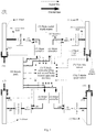
- an embodiment of the present invention provides a brake system 100 for a four-wheel drive electric vehicle.
- the brake system 100 is suitable for the four-wheel independent drive electric vehicle.
- the electric vehicle includes a battery pack 4, four motors 6 and a brake actuator 12.
- One motor 6 corresponds to one wheel 9.
- each motor 6 may be a wheel-side motor which is connected to a corresponding wheel 9 through a transmission 7 and a transmission shaft 8.
- each motor 6 may be a hub motor, and the transmission 7 may be omitted in the electric vehicle under the case of the hub motor, which facilitates layout of components of the electric vehicle.
- the electric vehicle further includes a wheel speed sensor 11, a resolver sensor 10 and a yaw rate sensor 5.
- the wheel speed sensor 11 is configured to detect a wheel speed signal of a corresponding wheel 9.
- the resolver sensor 10 is configured to detect a rotational speed signal of the corresponding motor 6.
- the yaw rate sensor 5 includes a longitudinal acceleration sensor, a lateral acceleration sensor and a yaw velocity sensor.
- the yaw velocity sensor is configured to detect a yaw velocity signal.
- the longitudinal acceleration sensor is configured to detect a longitudinal acceleration signal.
- the lateral acceleration sensor is configured to detect a lateral acceleration signal. It can be understood that the longitudinal acceleration sensor, the lateral acceleration sensor and the yaw velocity sensor can be integrated together. These signals can be used to control operations of the electric vehicle.
- the motor 6 generates a driving force for the corresponding wheel 9, that is, the motor 6 drives the wheel 9 to rotate, so as to enable the vehicle forward or backward.
- the motor 6 generates a braking force for the corresponding wheel 9, that is, the motor 6 hinders the wheel 9 from rotating, so as to enable the vehicle to slow down or to stop.
- the regenerative brake means that the motor 6 is not used as a driving motor but is used as a generator, the wheel 9 drives the motor 6 to generate power, a rotor of the motor 6 cuts magnetic induction lines of a stator of the motor 6 to generate reverse resistance so as to hinder the wheel 9 from rotating, thereby achieving an effect of speed reduction, and at the same time, the motor 6 generates recoverable electric energy.
- the reverse brake means that the current of the motor 6 is controlled to be reverse (the direction of the current of the motor 6 is opposite to the direction of the current producing the driving force by the motor 6 for the wheel 9), making the motor 6 to generate a reverse torque to hinder the wheel 9 from rotating, so as to make the rotational speed of the wheel 9 to decrease or to decrease to zero.
- the brake system 100 includes a vehicle controller 1, a signal detection sensor, and a motor controller 2.
- vehicle controller 1, the signal detection sensor and the motor controller 2 may communicate with each other through a controller area network (CAN) bus of the vehicle.
- CAN controller area network
- the battery pack 4 may be connected with the motor controller 2 through a high voltage wire.
- the brake system 100 includes four motor controllers 2. Each motor controller 2 may control the corresponding motor 6. The motor controller 2 may be connected with the corresponding motor 6 through the high voltage wire. Each motor 6 is configured to control the corresponding wheel 9 to operate, for example, generate the driving force or the braking force for the wheel 9.
- the signal detection sensor is configured to detect a brake pedal depth signal and a vehicle speed signal. In an embodiment of the present invention, the signal detection sensor is further configured to detect a brake pressure signal. In an embodiment of the present invention, the signal detection sensor includes a brake pedal depth sensor 3, a vehicle speed sensor 5A and a brake pressure sensor (not shown).
- the brake pedal depth sensor 3 is connected with a brake pedal of the vehicle and configured to detect the brake pedal depth signal.
- the brake pedal depth sensor 3 may generate a brake pedal depth signal indicating a brake depth of 0%; when the driver depresses the brake pedal, for example, when the depressed depth is 10% of the total depth of the brake pedal, the brake pedal depth sensor 3 may generate a brake pedal depth signal indicating a brake depth of 10%.
- the vehicle speed sensor 5A is configured to detect the vehicle speed signal.
- the brake pressure sensor is configured to detect the brake pressure signal.
- the brake pressure sensor is connected with the brake actuator 12.
- the brake pressure sensor detects a brake hydraulic pressure of the brake actuator 12, and outputs a brake pressure signal corresponding to the brake hydraulic pressure to the vehicle controller 1.
- the brake actuator 12 brakes the wheels 9, the brake toque of the brake actuator 12 may fail because the brake hydraulic pressure of the brake actuator 12 for a certain wheel 9 or multiple wheels 9 is abnormal, the vehicle controller 1 may determine the specific wheel 9 for which the hydraulic brake fails according to the brake pressure signal fed back by the brake pressure sensor.
- the vehicle controller 1 includes a first brake control unit and a second brake control unit. In an embodiment of the present invention, the first brake control unit and the second brake control unit are integrated into the vehicle controller 1. In an embodiment of the present invention, the vehicle controller 1 is further integrated with a brake stability control (BSC) unit and other control units.
- BSC brake stability control
- the first brake control unit is configured to determine a brake mode of the electric vehicle according to the brake pedal depth signal, to determine whether a current value of a state of charge (SOC) of the battery pack 4 is greater than a preset value of the SOC and to determine whether a vehicle speed value of the electric vehicle is less than a preset vehicle speed value according to the vehicle speed signal.
- SOC state of charge
- the first brake control unit determines that the electric vehicle is in the first brake mode.
- the first brake control unit determines that the electric vehicle is in the second brake mode.
- the second preset brake value is greater than the first preset brake value.
- the brake pedal depth value is carried in the brake pedal depth signal.
- the first preset brake value is a brake depth of 0%, that is to say, the brake pedal is not depressed.
- the second preset brake value is a brake depth of 30%, that is to say, the depth by which the brake pedal is depressed is 30% of the total depth of the brake pedal.
- the second preset brake value may also be understood as the depressed brake depth of another percentage of the total depth of the brake pedal; reference can be made to the relationship between damping of the brake pedal and the depth by which the brake pedal is depressed, performance of the vehicle, security of the vehicle and some other factor settings for the specific percentage.
- the first preset brake value and the second preset brake value may also be set to other percentages according to actual situations.
- the first brake mode may be configured as a mild brake mode of the vehicle
- the second brake mode may be configured as a sudden brake mode of the vehicle.
- the brake pedal depth is transformed according to the brake pedal depth.
- the first brake control unit is preset with a correspondence table of the brake pedal depth and the brake strength.
- the first brake control unit acquires the brake strength according to the collected brake pedal depth signal and the correspondence table, and determines whether the value of the brake strength is greater than a preset value of the brake strength to determine the brake mode of the vehicle.
- the brake pedal depth signal with the brake depth of 30% corresponds to the brake strength of 0.2 g (g is gravitational acceleration), and the preset value of the brake strength may be set to 0.2 g.
- the second brake control unit is configured to control the brake actuator 12 to brake the wheels 9 of the electric vehicle.
- the first brake control unit is configured to control the motor 6 to regeneratively brake the wheel 9 through the motor controller 2.
- the second brake control unit is configured to control the brake actuator 12 to brake the wheels 9 of the electric vehicle.
- the first brake control unit is configured to determine whether a brake torque of the brake actuator 12 on the wheels 9 fails according to the brake pressure signal.
- the first brake control unit is configured to control the motor 6 to regeneratively brake the wheel 9 through the motor controller 2.
- the first brake control unit is configured to control the motor 6 to reversely brake the wheel 9 through the motor controller 2.
- the motor 6 when the vehicle is in the first brake mode, it is determined whether the motor 6 is used to regeneratively brake the wheel 9 depending on the vehicle speed and the SOC of the battery pack 4 to determine.
- the SOC is generally represented with percentage, for example, 10% SOC indicates that the SOC of the battery pack 4 is 10% of the total state.
- the resistance which is generated when the wheel 9 drives the rotor of the motor 6 to cut the magnetic induction lines of the stator of the motor 6, is difficult to meet the requirement for slowing down or stopping the vehicle because the motor 6 has very low efficiency in a low speed state.
- the preset vehicle speed value is 10 km/h
- the preset value of the SOC is 90%.
- T indicates the brake torque which is in unit of Nm
- P n is the power of the motor 6 which is in unit of kW
- n is a rotational speed of the motor 6
- n 0 is a preset rotational speed of the motor 6
- n and n 0 are in unit of r/m
- k1 indicates the brake pedal depth which ranges from 0% to 100%, for example, 30%
- k2 indicates the correction coefficient of the brake pedal depth.
- the maximum total brake torque Tam provided by the four motors 6 is at least equivalent to the maximum hydraulic brake torque (for example, the maximum hydraulic brake torque provided by four brake calipers) provided by the brake actuator 12. That is, when there is no brake actuator 12, the brake system 100 also can achieve the same effect (for example, the same brake distance or brake deceleration) as using the brake actuator 12 by only using the motors 6 to brake the wheels 9. In this case, where the brake toque of the brake actuator 12 can meet the brake torque required by the driver, the brake toque of the motors 6 also can meet the brake torque required by the driver.
- the brake torque required by the driver may be acquired through the brake pedal depth signal, for example, the maximum brake torque required by the driver is the brake torque required when the brake pedal is floored; at this point, the brake pedal depth signal is a signal with a brake depth of 100%.
- the maximum brake torque required by the driver is not greater than the maximum brake torque Tam provided by the four motors 6.
- the first brake control unit allocates the total brake torque Ta to the four motors 6 according to an ideal front-rear shaft braking force allocation curve (that is, curve I).
- the brake torque allocated to the front shaft is k3 ⁇ Ta
- the brake torque allocated to the rear shaft is (1-k3) ⁇ Ta
- the first brake control unit calculates currents required by the four motors 6 respectively according to the allocated brake torques.
- the first brake control unit sends a brake torque allocation signal to the four motor controllers 2 respectively.
- the wheel 9 drives the rotor of the motor 6 to cut the magnetic induction lines generated by the stator of the motor 6, the motor 6 outputs electric energy, and the first brake control unit stores the electric energy generated by the motor 6 into the battery pack 4.
- the second brake control unit may be an ABS.
- the first brake control unit allocates the total brake torque Tn2 to the brake actuator 12 according to the ideal front-rear shaft braking force allocation curve (that is, curve I). Reference can be made to the allocation principle of the total brake torque Ta provided by the motors 6 for an allocation principle.
- the first brake control unit sends a brake torque allocation signal to the second brake control unit.
- the second brake control unit controls the brake actuator 12 to brake the wheels 9 of the electric vehicle according to the brake torque allocation signal.
- the brake actuator 12 includes a brake master cylinder, a wheel cylinder, a brake disc and a brake caliper.
- the brake disc is mounted on a hub and rotates together with the wheel.
- a pushing rod connecting the brake pedal with the brake master cylinder will make the brake master cylinder generate a hydraulic pressure.
- the hydraulic pressure generated by the brake master cylinder is transferred to the wheel cylinder.
- the wheel cylinder applies a pressure to the brake caliper to generate a friction force for the brake disc, thus braking the corresponding wheel 9.
- the second brake control unit allocates the total brake torque Tn2 to each wheel 9 according to the brake torque allocation signal.
- the brake actuator 12 brakes the corresponding wheel 9 according to allocation of the brake torque.
- the first brake control unit can determine whether the brake torque of the brake actuator 12 on the wheels 9 fails according to the brake pressure signal.
- the brake pressure signal For example, the brake pedal depth signal and the brake pressure signal have an one-to-one correspondence.
- brake pressure signals of the four wheels 9 collected by the first brake control unit are normal brake pressure signals.
- the first brake control unit determines that a brake torque of the brake actuator 12 on the wheel 9 corresponding to the abnormal brake pressure signal fails.
- the first brake control unit determines the vehicle speed and the SOC of the battery pack 4. When the vehicle speed value is less than a preset vehicle speed value, or the current value of the SOC is greater than a preset value of the SOC, as it is inappropriate for the motor 6 to brake the wheel 9 in a regenerative brake manner at this point, the first brake control unit controls the motor 6 to reversely brake the wheel 9 through the motor controller 2.
- the brake torque T provided by the motor 6 may be allocated to the brake torque T' of the hydraulic brake corresponding to the one or more wheels 9, and the motor controller 2 makes the motor 6 generate a reverse torque according to a current required by the motor 6, thus making the rotational speed of the wheel 9 decrease or decrease to zero, to achieve a brake effect.
- the hydraulic brake corresponding to the left front wheel 9 fails.
- the first brake control unit adjusts a transmission ratio i of the transmission 7 through a transmission controller (not shown) and adjusts a current I of the motor 6 through the motor controller 2, to make the brake torque T provided by the motor 6 corresponding to the left front wheel 9 equal to the required brake torque T1.
- the transmission ratio i of the transmission 7 and the current I of the motor 6 are non-continuous fixed values, and it is difficult to precisely make the brake torque T provided by the motor 6 equal to the required brake torque T1; therefore, the first brake control unit makes them equal to meet the brake requirement by adjusting the correction coefficient k2 of the brake pedal depth.
- the second brake control unit controls the brake actuator 12 to brake the wheels 9 without intervention of brake of the motor 6.
- the first brake control unit determines the brake mode of the electric vehicle through the brake pedal depth signal, and takes different brake measures in different brake modes and on different working conditions of the vehicle to make the brake of the motor 6 and the brake of the brake actuator 12 cooperate with each other. At the same time, when the brake of the brake actuator 12 on the wheel 9 fails, the first brake control unit can control the motor 6 to brake the wheel 9, which effectively reduces the vehicle crash risk brought about by brake failure.
- an embodiment of the present invention provides a brake method for a four-wheel drive electric vehicle.
- the brake method may be implemented by the brake system 100 for a four-wheel drive electric vehicle in any above embodiments.
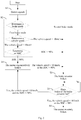
- the brake method includes the followings:
- the signal detection sensor includes a brake pedal depth sensor 3, a vehicle speed sensor 5A and a brake pressure sensor.
- the brake pedal depth sensor 3 is connected with the brake pedal of the vehicle and detects the brake pedal depth signal.
- the vehicle speed sensor 5A detects the vehicle speed signal.
- the brake pressure sensor detects the brake pressure signal.
- the brake pressure sensor is connected with the brake actuator 12.
- the brake pressure sensor detects a brake hydraulic pressure of the brake actuator 12, and outputs the brake pressure signal corresponding to the brake hydraulic pressure to the vehicle controller 1.
- the first brake control unit may determine the specific wheel 9 for which the hydraulic brake fails according to the brake pressure signal fed back by the brake pressure sensor.
- the first brake control unit when a brake pedal depth value is greater than a first preset brake value and less than a second preset brake value, the first brake control unit is configured to determine that the electric vehicle is in the first brake mode. When the brake pedal depth value is greater than the second preset brake value, the first brake control unit is configured to determine that the electric vehicle is in the second brake mode, and the second preset brake value is greater than the first preset brake value.
- the brake pedal depth value is carried in the brake pedal depth signal.
- the first preset brake value is a brake depth of 0%.
- the second preset brake value is a brake depth of 30%.
- the SOC of the battery pack 4 is generally represented by percentage, for example, the SOC 10% indicates that the SOC of the battery pack 4 is 10% of the total state.
- the present value of the SOC is 90%, and the preset vehicle speed value is 10 km/h.
- the second brake control unit controls the brake actuator 12 to brake the wheels 9 of the electric vehicle without intervention of brake of the motor 6.
- the motor controller 2 controls a required current to be input into the motor 6 according to the current required by the motor 6 and calculated by the first brake control unit, to make the stator of the motor 6 generate a magnetic field, which generates rotation resistance for the rotor and thus reduces the rotational speed of the wheel 9.
- the wheel 9 drives the rotor of the motor 6 to cut the magnetic induction lines generated by the stator of the motor 6, the motor 6 outputs electric energy, and the first brake control unit stores the electric energy generated by the motor 6 into the battery pack 4.
- the second situation is from S1-> S2 -> S3-> S5-> S4: that is, when the brake torque of the brake actuator 12 on the wheels 9 fails and the vehicle speed value is not less than the preset vehicle speed value and the current value of the SOC is not greater than the preset value of the SOC, the first brake control unit controls the motor 6 to regeneratively brake the wheel 9 through the motor controller 2.
- the brake torque T provided by the motor 6 may be allocated to the brake torque T1 of the hydraulic brake corresponding to the one or more wheels 9, and the motor controller 2 makes the stator of the motor 6 generate a magnetic field that hinders the rotor of the motor 6 from rotating according to a current required by the motor 6, thus making the rotational speed of the wheel 9 decrease or decrease to zero, to achieve a brake effect.
- the hydraulic brake corresponding to the left front wheel 9 fails.
- the first brake control unit adjusts a transmission ratio i of the transmission 7 through a transmission controller and adjusts a current I of the motor 6 through the motor controller 2, to make the brake torque T provided by the motor 6 corresponding to the left front wheel 9 equal to the required brake torque T1.
- the transmission ratio i of the transmission 7 and the current I of the motor 6 are non-continuous fixed values, and it is difficult to precisely make the brake torque T provided by the motor 6 equal to the required brake torque T1; therefore, the first brake control unit makes them equal to meet the brake requirement by adjusting the brake correction coefficient k2 of the pedal depth.
- the first brake control unit can determine according to the brake pressure signal whether the brake torque of the brake actuator 12 on the wheels 9 fails.
- the brake pedal depth signal and the brake pressure signal have an one-to-one correspondence.
- brake pressure signals of the four wheels 9 collected by the first brake control unit are normal brake pressure signals.
- the first brake control unit determines that a brake torque of the brake actuator 12 on the wheel 9 corresponding to the abnormal brake pressure signal fails.
- the first brake control unit determines the vehicle speed and the SOC of the battery pack.
- the first brake control unit controls the motor 6 to reversely brake the wheel 9 through the motor controller 2.
- the brake torque provided by the motor 6 may be allocated to the brake torque of the hydraulic brake corresponding to the one or more wheels 9, and the motor controller 2 makes the motor 6 to generate a reverse torque according to a current required by the motor 6, thus making the rotational speed of the wheel 9 to decrease or to decrease to zero, so as to achieve a brake effect.
- the hydraulic brake corresponding to the left front wheel 9 fails.
- the first brake control unit adjusts a transmission ratio i of the transmission 7 through a transmission controller and adjusts a current I of the motor 6 through the motor controller 2, to make the brake torque T provided by the motor 6 corresponding to the left front wheel 9 equal to the required brake torque T1.
- the transmission ratio i of the transmission 7 and the current I of the motor 6 are non-continuous fixed values, and it is difficult to precisely make the brake torque T provided by the motor 6 equal to the required brake torque T1; therefore, the first brake control unit makes them equal to meet the brake requirement by adjusting the correction coefficient k2 of the brake pedal depth.
- the first brake control unit determines the brake mode of the electric vehicle through the brake pedal depth signal, and takes different brake measures in different brake modes and on different working conditions of the vehicle to make the brake of the motor and the brake of the brake actuator cooperate with each other. At the same time, when the brake of the brake actuator on the wheel fails, the first brake control unit can control the motor to brake the wheel, which effectively reduces the vehicle crash risk brought about by brake failure.
- Embodiments of the present invention also provide a four-wheel drive electric vehicle, the electric vehicle including the brake system 100 for a four-wheel drive electric vehicle as stated above; a battery pack; a motor; and a brake actuator, in which the battery pack, the motor and the brake actuator are connected with the brake system for a four-wheel drive electric vehicle respectively. Therefore, the electric vehicle can effectively reduce the vehicle crash risk brought about by brake failure.
- an embodiment means that a particular feature, structure, material, or characteristic described in connection with the embodiment or example is included in at least one embodiment or example of the present invention.
- the schematic expressions of the terms are not necessarily referring to the same embodiment or example of the present invention.
- the particular features, structures, materials, or characteristics may be combined in any suitable manner in one or more embodiments or examples.
- Logics and/or steps expressed in the flow chart or described herein in other manners can be considered to be a sequencing list of executable instructions configured to implement logical functions, and can be specifically implemented in any computer readable medium, to be used by an instruction executing system, apparatus or device (for example, a computer based system, a system including a processor or another system that can read an instruction from the instruction executing system, apparatus or device and execute the instruction), or used in combination with the instruction executing systems, apparatuses or devices.
- the "computer readable medium” may be any apparatus that can include, store, communicate, propagate or transmit a program to be used by the instruction executing systems, apparatuses or devices or used in combination with the instruction executing systems, apparatuses or devices.
- a more specific example (non-exhaustive list) of the computer readable medium includes the following: an electrical connecting portion (electronic apparatus) having one or more wires, a portable computer disk box (magnetic apparatus), a random access memory (RAM), a read only memory (ROM), an erasable programmable read only memory (EPROM or a flash memory), an optical fiber apparatus, and a portable compact disc read only memory (CDROM).
- the computer readable medium may even be a piece of paper on which the program can be printed or another suitable medium, because the program can be obtained in an electronic manner, for example, by performing optical scanning on the paper or another medium and then editing, decoding or, if necessary, processing it in other suitable manners, which is then stored in a computer memory.
- the functional units in the various embodiments of the present invention may be integrated into one processing module, or each of the units may exist alone physically, or two or more units may be integrated into one module.
- the integrated module may be implemented in the form of hardware, or may be implemented in the form of a software functional module.
- the integrated module may also be stored in a computer readable storage medium if implemented in the form of a software functional module and sold or used as a separate product.
- the storage medium mentioned above may be a read only memory, a magnetic disk, an optical disc, or the like.
Landscapes
- Engineering & Computer Science (AREA)
- Transportation (AREA)
- Mechanical Engineering (AREA)
- Power Engineering (AREA)
- Life Sciences & Earth Sciences (AREA)
- Sustainable Development (AREA)
- Sustainable Energy (AREA)
- Physics & Mathematics (AREA)
- Electromagnetism (AREA)
- Electric Propulsion And Braking For Vehicles (AREA)
- Regulating Braking Force (AREA)
Claims (13)
- Système de freinage (100) pour un véhicule électrique à quatre roues motrices, comprenant :un contrôleur de véhicule (1), comprenant une première unité de commande de frein et une seconde unité de commande de frein ;un capteur de détection de signal, configuré pour détecter un signal de profondeur de pédale de frein et un signal de vitesse du véhicule ; etun contrôleur de moteur (2), dans lequel,la première unité de commande de frein est configurée pour déterminer un mode de freinage du véhicule électrique en fonction du signal de profondeur de pédale de frein, pour déterminer si une valeur actuelle d'un état de charge pour un bloc de batteries (4) du véhicule électrique est supérieure à une valeur préréglée de l'état de charge et pour déterminer si une valeur de vitesse du véhicule électrique est inférieure à une valeur de vitesse préréglée du véhicule en fonction du signal de vitesse du véhicule, dans lequel le mode de freinage du véhicule électrique comprend un premier mode de freinage et un deuxième mode de freinage ;le contrôleur de moteur (2) est configuré pour commander un moteur (6) du véhicule électrique afin de freiner par régénération une roue (9) du véhicule électrique lorsque le véhicule électrique est dans le premier mode de freinage, que la valeur de la vitesse du véhicule est supérieure ou égale à la valeur de vitesse préréglée du véhicule et que la valeur actuelle de l'état de charge est inférieure ou égale à la valeur préréglée de l'état de charge ; etla deuxième unité de commande de frein est configurée pour commander un actionneur de frein (12) du véhicule électrique afin de freiner les roues (9) du véhicule électrique lorsque le véhicule électrique est dans le premier mode de freinage et que la valeur de la vitesse du véhicule est inférieure à la valeur de vitesse préréglée du véhicule, ou lorsque le véhicule électrique est dans le premier mode de freinage et que la valeur actuelle de l'état de charge est supérieure à la valeur préréglée de l'état de charge, ou lorsque le véhicule électrique est dans le deuxième mode de freinage,caractérisé en ce quele capteur de détection de signal est en outre configuré pour détecter un signal de pression de freinage ;la première unité de commande de frein est en outre configurée pour déterminer si un couple de freinage de l'actionneur de frein sur les roues (9) défaille dans un processus de freinage des roues (9) par l'actionneur de frein (12) en fonction du signal de pression de freinage ; etle contrôleur de moteur (2) est en outre configuré pour commander le moteur (6) afin de freiner la roue (9) par régénération lorsque le couple de freinage de l'actionneur de frein (12) sur les roues (9) est défaillant et que la valeur de la vitesse du véhicule est supérieure ou égale à la valeur de vitesse préréglée du véhicule et que la valeur actuelle de l'état de charge est inférieure ou égale à la valeur préréglée de l'état de charge et de commander le moteur (6) pour freiner en sens inverse la roue (9) lorsque le couple de freinage de l'actionneur de frein (12) sur les roues (9) est défaillant et que la valeur de la vitesse du véhicule est inférieure à la valeur de vitesse préréglée du véhicule, ou lorsque le couple de freinage de l'actionneur de frein (12) sur les roues (9) est défaillant et que la valeur actuelle de l'état de charge est supérieure à la valeur préréglée de l'état de charge.
- Système de freinage (100) pour un véhicule électrique à quatre roues motrices selon la revendication 1, dans lequel le contrôleur de moteur (2) est en outre configuré pour :acquérir un couple de freinage actuel attribué à la roue (9) lorsque le couple de freinage de l'actionneur de frein (12) sur les roues (9) est défaillant ;déterminer un coefficient de correction (k2) d'une profondeur de pédale de frein (k1) en fonction du couple de freinage actuel lorsque l'actionneur de frein (12) est défaillant ; etobtenir un couple de freinage du moteur (6) pour la roue (9) en fonction de la puissance du moteur (6), d'une vitesse de rotation du moteur (6), de la profondeur de pédale de frein (k1) et du coefficient de correction (k2) de la profondeur de pédale de frein (k1), et dans lequel en particulier le couple de freinage du moteur pour la roue est déterminé selon une formule de

- Système de freinage (100) d'un véhicule électrique à quatre roues motrices selon l'une quelconque des revendications 1 à 2, dans lequel
la première unité de commande de freinage est configurée pour déterminer que le véhicule électrique est dans le premier mode de freinage lorsqu'une valeur de profondeur de pédale de frein est supérieure à une première valeur de freinage préréglée et inférieure à une deuxième valeur de freinage préréglée ; et
la première unité de commande de freinage est configurée pour déterminer que le véhicule électrique est en mode de freinage secondaire lorsque la valeur de la profondeur de la pédale de frein (k1) est supérieure à la deuxième valeur de freinage préréglée,
dans laquelle la deuxième valeur de freinage préréglée est supérieure à la première valeur de freinage préréglée, et la valeur de la profondeur de pédale de frein (k1) est reportée dans le signal de profondeur de pédale de frein. - Système de freinage (100) pour un véhicule électrique à quatre roues motrices selon l'une quelconque des revendications 1 à 3, dans lequel la première unité de commande de freinage est configurée pour stocker l'énergie électrique générée par le moteur (6) dans le bloc de batteries (4) lorsque le moteur (6) freine la roue (9) par régénération.
- Système de freinage (9) pour un véhicule électrique à quatre roues motrices selon l'une quelconque des revendications 1 à 4, dans lequel le capteur de détection de signal comprend un capteur de profondeur de pédale de frein (3), un capteur de vitesse du véhicule (5A) et un capteur de pression de freinage ;
le capteur de profondeur de pédale de frein (3) est configuré pour détecter le signal de profondeur de pédale de frein ;
le capteur de vitesse du véhicule (5A) est configuré pour détecter le signal de vitesse du véhicule ; et
le capteur de pression de freinage est configuré pour détecter le signal de pression de freinage. - Système de freinage (100) pour un véhicule électrique à quatre roues motrices selon l'une des revendications 1 à 5, dans lequel la première unité de commande de freinage et la deuxième unité de commande de freinage sont intégrées dans le contrôleur du véhicule (1).
- Système de freinage (100) pour un véhicule électrique à quatre roues motrices selon l'une quelconque des revendications 2 à 5, dans lequel le véhicule électrique comprend quatre moteurs (6), et le couple de freinage lorsqu'une pédale de frein est enfoncée est calibré comme étant le couple de freinage maximal fourni par les quatre moteurs (6) lorsque le couple de freinage de l'actionneur de frein (12) est complètement défaillant.
- Procédé de freinage pour un véhicule électrique à quatre roues motrices comprenant :détecter (S1) un signal de profondeur de pédale de frein et un signal de vitesse du véhicule ;déterminer (S2) un mode de freinage du véhicule électrique en fonction du signal de profondeur de pédale de frein, si une valeur actuelle d'un état de charge d'un bloc de batteries (4) du véhicule électrique est supérieure à une valeur préréglée de l'état de charge et si une valeur de vitesse du véhicule électrique est inférieure à une valeur de vitesse préréglée du véhicule en fonction du signal de vitesse du véhicule, dans lequel le mode de freinage du véhicule électrique comprend un premier mode de freinage et un second mode de freinage ;commander (S3) un actionneur de frein (12) du véhicule électrique pour freiner les roues (6) du véhicule électrique lorsque le véhicule électrique est dans le premier mode de freinage et que la valeur de vitesse du véhicule est inférieure à la valeur de vitesse préréglée du véhicule, ou lorsque le véhicule électrique est dans le premier mode de freinage et que la valeur actuelle de l'état de charge est supérieure à la valeur préréglée de l'état de charge, ou lorsque le véhicule électrique est dans le deuxième mode de freinage ; etcommander (S4) un moteur (6) du véhicule électrique pour freiner une roue (9) par régénération lorsque le véhicule électrique est dans le premier mode de freinage et que la valeur de vitesse du véhicule est supérieure ou égale à la valeur préréglée de vitesse du véhicule et que la valeur actuelle de l'état de charge est égale ou inférieure à la valeur préréglée de l'état de charge,caractérisé par le fait qu'il comprend en outredétecter (S1) un signal de pression de freinage;déterminer (S5) si un couple freinage de l'actionneur de frein (12) sur les roues (9) défaille dans un processus de freinage des roues par actionneur selon le signal de pression de freinage;commander (S4) le moteur (6) pour freiner la roue par régénération lorsque le couple de l'actionneur de frein sur les roues est défaillant et la valeur de vitesse du véhicule est supérieure ou égale à la valeur préréglée de vitesse du véhicule et que la valeur actuelle de l'état de charge est inférieure ou égale à la valeur préréglée de l'état de charge; etcommander (S6) le moteur (6) pour freiner en sens inverse la roue (9) lorsque le couple de freinage de l'actionneur de frein sur les roues (9) est défaillant et que la valeur de vitesse du véhicule est inférieure à la valeur de vitesse préréglée du véhicule ou lorsque le couple de freinage de l'actionneur de frein (12) sur les roues (9) est défaillant et que la valeur actuelle de l'état de charge est supérieure à la valeur préréglée de l'état de charge.
- Procédé de freinage pour un véhicule électrique à quatre roues motrices selon la revendication 8, comprenant en outre
acquérir un couple de freinage actuel attribué à la roue (9) lorsque le couple de freinage de l'actionneur de frein sur les roues (9) est défaillant ;
déterminer un coefficient de correction de profondeur de pédale de frein (k1) en fonction du couple de freinage actuel lorsque l'actionneur de frein est défaillant
obtenir un couple de freinage du moteur (6) pour la roue (9) en fonction de la puissance du moteur (6), d'une vitesse de rotation du moteur (6), de la profondeur de pédale de frein (k1) et du coefficient de correction (k2) de profondeur de pédale de frein (k1). - Procédé de freinage pour un véhicule électrique à quatre roues motrices selon la revendication 9, dans lequel le couple de freinage du moteur pour la roue est déterminé selon une formule

- Procédé de freinage pour un véhicule électrique à quatre roues motrices selon l'une quelconque des revendications 8 à 10, dans lequel l'acte de détermination d'un mode de freinage du véhicule électrique en fonction du signal de profondeur de pédale de frein comprend :déterminer que le véhicule électrique est dans le premier mode de freinage lorsqu'une valeur de profondeur de pédale de frein est supérieure à une première valeur de freinage préréglée et inférieure à une deuxième valeur de freinage prérégléedéterminer que le véhicule électrique est dans le deuxième mode de freinage lorsque la valeur de profondeur de pédale de frein est supérieure à la deuxième valeur de freinage préréglée,dans lequel la deuxième valeur de freinage préréglée est supérieure à la première valeur de freinage préréglée, et la valeur de profondeur de pédale de frein est reportée dans le signal de profondeur de pédale de frein.
- Procédé de freinage pour un véhicule électrique à quatre roues motrices selon l'une quelconque des revendications 8 à 11, dans lequel l'acte de commander le moteur pour freiner la roue par régénération comprend :
stocker l'énergie électrique produite par le moteur dans le bloc de batteries. - Véhicule électrique à quatre roues motrices, comprenant :le système de freinage (100) d'un véhicule électrique à quatre roues motrices selon l'une des revendications 1 à 7 ;un bloc de batteries (4) ;un moteur (6) ; etun actionneur de frein (12),dans lequel le bloc de batteries (4), le moteur (6) et l'actionneur de frein (12) sont respectivement reliés au système de freinage (100) pour un véhicule électrique à quatre roues motrices.
Applications Claiming Priority (2)
| Application Number | Priority Date | Filing Date | Title |
|---|---|---|---|
| CN201510487944.0A CN106427601B (zh) | 2015-08-11 | 2015-08-11 | 基于四轮驱动的电动汽车的制动系统及方法及电动汽车 |
| PCT/CN2016/094455 WO2017025041A1 (fr) | 2015-08-11 | 2016-08-10 | Système de freinage et procédé pour véhicule électrique à quatre roues motrices et véhicule électrique |
Publications (3)
| Publication Number | Publication Date |
|---|---|
| EP3334619A1 EP3334619A1 (fr) | 2018-06-20 |
| EP3334619A4 EP3334619A4 (fr) | 2018-08-08 |
| EP3334619B1 true EP3334619B1 (fr) | 2021-03-31 |
Family
ID=57983069
Family Applications (1)
| Application Number | Title | Priority Date | Filing Date |
|---|---|---|---|
| EP16834665.8A Active EP3334619B1 (fr) | 2015-08-11 | 2016-08-10 | Système de freinage et procédé pour véhicule électrique à quatre roues motrices et véhicule électrique |
Country Status (4)
| Country | Link |
|---|---|
| US (1) | US10723227B2 (fr) |
| EP (1) | EP3334619B1 (fr) |
| CN (1) | CN106427601B (fr) |
| WO (1) | WO2017025041A1 (fr) |
Cited By (1)
| Publication number | Priority date | Publication date | Assignee | Title |
|---|---|---|---|---|
| EP4438421A1 (fr) * | 2023-03-30 | 2024-10-02 | Xiaomi EV Technology Co., Ltd. | Procédé, dispositif et système de commande de freinage, véhicule, support et puce |
Families Citing this family (31)
| Publication number | Priority date | Publication date | Assignee | Title |
|---|---|---|---|---|
| JP7073620B2 (ja) * | 2016-10-31 | 2022-05-24 | ヤマハ株式会社 | アクチュエータの駆動制御装置 |
| CN113968294B (zh) * | 2018-10-11 | 2023-02-28 | 北京骑胜科技有限公司 | 控制方法、控制装置、电动车和计算机可读存储介质 |
| CN111252048B (zh) * | 2018-11-30 | 2021-04-20 | 比亚迪股份有限公司 | 控制车辆制动的方法、装置、存储介质及车辆 |
| CN109532800A (zh) * | 2018-12-19 | 2019-03-29 | 广东卡达克汽车科技有限公司 | 一种防制动油路失效系统 |
| CN110254405B (zh) * | 2019-06-25 | 2021-08-06 | 吉林大学 | 一种面向自动驾驶与智能辅助驾驶的汽车线控制动控制系统及其控制方法 |
| CN112971609B (zh) * | 2019-12-02 | 2025-05-06 | 广东美的白色家电技术创新中心有限公司 | 跨越障碍物的装置及清洁装置 |
| CN110979025B (zh) * | 2019-12-26 | 2021-07-20 | 潍柴动力股份有限公司 | 轮边电机动力系统及其控制方法、故障处理方法 |
| JP7310640B2 (ja) * | 2020-02-19 | 2023-07-19 | トヨタ自動車株式会社 | 4輪駆動車両 |
| JP7361882B2 (ja) * | 2020-02-25 | 2023-10-16 | 株式会社ユニバンス | 制動装置 |
| DE102020107548A1 (de) * | 2020-03-19 | 2021-09-23 | Ford Global Technologies Llc | Kraftfahrzeug und Verfahren zum Betreiben eines Kraftfahrzeugs |
| ES2875198B2 (es) * | 2020-05-04 | 2022-06-20 | Cecotec Res And Development | Sistema de gestion de frenado en vehiculo electrico de dos ruedas |
| CN111645528B (zh) * | 2020-06-05 | 2022-02-11 | 中国第一汽车股份有限公司 | 制动能量回收控制方法、系统、装置、车辆及存储介质 |
| CN113859217A (zh) * | 2020-06-12 | 2021-12-31 | 芜湖伯特利汽车安全系统股份有限公司 | 自动驾驶车辆的集成控制电子机械制动系统 |
| DE102020207422B4 (de) * | 2020-06-16 | 2025-12-31 | Zf Friedrichshafen Ag | Verfahren zum Betreiben eines elektrischen Antriebsstrangs einer Arbeitsmaschine, elektrischer Antriebsstrang für eine Arbeitsmaschine und Arbeitsmaschine |
| DE102020118987A1 (de) * | 2020-07-17 | 2022-01-20 | Infineon Technologies Ag | Redundante energieversorgung für bremssystem |
| CN111907335A (zh) * | 2020-08-10 | 2020-11-10 | 辽宁工程技术大学 | 一种基于无刷双馈电机驱动的电动汽车再生制动控制方法 |
| CN114572011B (zh) * | 2020-11-30 | 2024-05-28 | 长城汽车股份有限公司 | 一种物流车制动控制方法与系统 |
| US12071119B2 (en) * | 2021-02-24 | 2024-08-27 | Textron Innovations Inc. | Emergency vehicle braking using closed-loop pulsing |
| CN113291161B (zh) * | 2021-05-21 | 2024-01-26 | 上海智蕙林医疗科技有限公司 | 一种agv小车及自动阻止滑行的方法 |
| CN113276807A (zh) * | 2021-05-28 | 2021-08-20 | 朱芮叶 | 电动汽车能源回收系统失效处理方法、装置、汽车及介质 |
| CN113246739A (zh) * | 2021-06-17 | 2021-08-13 | 中国第一汽车股份有限公司 | 一种混合动力车辆及其制动控制方法 |
| CN113263918B (zh) * | 2021-06-30 | 2023-06-23 | 北京车和家信息技术有限公司 | 能量回收控制方法及装置 |
| CN113765443A (zh) * | 2021-08-30 | 2021-12-07 | 武汉理工大学 | 电动助力制动控制方法及其设计仿真方法、设备及介质 |
| CN115158260B (zh) * | 2022-06-27 | 2024-01-23 | 湖北文理学院 | 汽车制动系统及汽车制动方法 |
| CN115140001B (zh) * | 2022-08-17 | 2024-05-03 | 杭叉集团股份有限公司 | 一种重装电动叉车电液复合制动系统及控制方法 |
| CN115648969B (zh) * | 2022-11-09 | 2025-06-10 | 北汽福田汽车股份有限公司 | 车辆控制方法、装置、存储介质、电子设备及车辆 |
| CN120457059A (zh) * | 2023-04-28 | 2025-08-08 | 深圳引望智能技术有限公司 | 制动方法及相关装置、系统 |
| CN117533292B (zh) * | 2023-09-11 | 2024-07-16 | 比亚迪股份有限公司 | 车辆控制系统、控制方法、控制器及车辆 |
| KR20250040876A (ko) * | 2023-09-11 | 2025-03-25 | 비와이디 컴퍼니 리미티드 | 차량 제어 시스템 및 방법, 및 차량 |
| CN121448181A (zh) * | 2024-07-31 | 2026-02-03 | 比亚迪股份有限公司 | 车辆控制方法、车辆控制系统、车辆及存储介质 |
| CN119568160A (zh) * | 2024-12-31 | 2025-03-07 | 小米汽车科技有限公司 | 一种车辆控制方法、装置、车辆及介质 |
Family Cites Families (27)
| Publication number | Priority date | Publication date | Assignee | Title |
|---|---|---|---|---|
| JP3365301B2 (ja) * | 1998-03-19 | 2003-01-08 | トヨタ自動車株式会社 | 車両の制動エネルギー制御装置とその制御方法 |
| JP2004268901A (ja) | 2003-02-18 | 2004-09-30 | Nissan Motor Co Ltd | 制動制御装置 |
| JP2005153790A (ja) | 2003-11-27 | 2005-06-16 | Nissan Motor Co Ltd | 4輪駆動車両 |
| JP4825668B2 (ja) * | 2004-10-06 | 2011-11-30 | 日立オートモティブシステムズ株式会社 | 電動ブレーキ装置 |
| JP5010836B2 (ja) * | 2006-02-27 | 2012-08-29 | 日立オートモティブシステムズ株式会社 | モータ駆動装置,モータ駆動方法、及び電動ブレーキ装置 |
| US7553255B2 (en) | 2006-10-13 | 2009-06-30 | Ford Global Technologies, Llc. | Locker clutch control for a differential mechanism |
| JP4258548B2 (ja) * | 2006-12-19 | 2009-04-30 | トヨタ自動車株式会社 | 車両およびその制御方法 |
| JP2009227221A (ja) * | 2008-03-25 | 2009-10-08 | Mitsuba Corp | ハイブリッド電気自動車 |
| US9024550B2 (en) * | 2009-01-16 | 2015-05-05 | International Business Machines Corporation | Dynamic reconfiguration-switching of windings in an electric motor used as a generator in an electric vehicle |
| CN201400078Y (zh) * | 2009-05-08 | 2010-02-10 | 比亚迪股份有限公司 | 一种电动汽车 |
| CN101648523A (zh) * | 2009-09-04 | 2010-02-17 | 奇瑞汽车股份有限公司 | 一种电动汽车制动能量回收系统及其控制方法 |
| JP2011240740A (ja) | 2010-05-14 | 2011-12-01 | Advics Co Ltd | 車両の制動制御装置 |
| DE102010042995A1 (de) * | 2010-10-27 | 2012-05-03 | Robert Bosch Gmbh | Steuervorrichtung und Verfahren zum Betreiben eines mit einer elektrischen Antriebs- und/oder Generatorvorrichtung ausgestatteten Bremssystems |
| SI2737621T1 (sl) * | 2011-07-26 | 2022-10-28 | Moog Inc. | Vpenjalni sistem z električnim motorjem |
| US20130162009A1 (en) | 2011-12-22 | 2013-06-27 | Coda Automotive, Inc. | Electric vehicle regenerative braking system |
| JP5862771B2 (ja) * | 2012-05-21 | 2016-02-16 | トヨタ自動車株式会社 | 車両用ブレーキシステム |
| JP2014061835A (ja) * | 2012-09-24 | 2014-04-10 | Hitachi Automotive Systems Ltd | ブレーキ制御装置 |
| CN103332184B (zh) | 2013-06-08 | 2016-03-02 | 北京航空航天大学 | 一种电动汽车用电液复合制动控制方法及其控制装置 |
| US9657786B2 (en) | 2013-11-26 | 2017-05-23 | Magna Powertrain Of America, Inc. | Torque transfer mechanism with sealed ball-ramp clutch operator unit |
| CN104276050B (zh) * | 2014-01-30 | 2015-08-26 | 比亚迪股份有限公司 | 车辆及其的制动回馈控制方法 |
| CN104494599B (zh) * | 2014-01-30 | 2015-11-25 | 比亚迪股份有限公司 | 车辆及其的滑行回馈控制方法 |
| KR101583942B1 (ko) * | 2014-06-17 | 2016-01-11 | 현대자동차주식회사 | 구동모터 제어방법 및 제어장치 |
| CN104890669B (zh) | 2015-06-10 | 2017-12-12 | 安徽工业大学 | 一种混合动力汽车动力总成控制方法 |
| KR102590731B1 (ko) * | 2016-09-02 | 2023-10-19 | 에이치엘만도 주식회사 | Ecm 시스템의 페일세이프 장치 및 그 방법 |
| DE102017200978A1 (de) * | 2017-01-23 | 2018-07-26 | Audi Ag | Verfahren zum Betreiben eines Fahrzeugs |
| US10189476B1 (en) * | 2017-10-13 | 2019-01-29 | Zoox, Inc. | Brake force distribution |
| US10647311B2 (en) * | 2017-11-09 | 2020-05-12 | Robert Bosch Gmbh | System and method for motor brake boost function failure |
-
2015
- 2015-08-11 CN CN201510487944.0A patent/CN106427601B/zh active Active
-
2016
- 2016-08-10 EP EP16834665.8A patent/EP3334619B1/fr active Active
- 2016-08-10 WO PCT/CN2016/094455 patent/WO2017025041A1/fr not_active Ceased
- 2016-08-10 US US15/750,042 patent/US10723227B2/en active Active
Non-Patent Citations (1)
| Title |
|---|
| None * |
Cited By (1)
| Publication number | Priority date | Publication date | Assignee | Title |
|---|---|---|---|---|
| EP4438421A1 (fr) * | 2023-03-30 | 2024-10-02 | Xiaomi EV Technology Co., Ltd. | Procédé, dispositif et système de commande de freinage, véhicule, support et puce |
Also Published As
| Publication number | Publication date |
|---|---|
| EP3334619A1 (fr) | 2018-06-20 |
| CN106427601B (zh) | 2019-02-26 |
| EP3334619A4 (fr) | 2018-08-08 |
| US10723227B2 (en) | 2020-07-28 |
| CN106427601A (zh) | 2017-02-22 |
| US20180229610A1 (en) | 2018-08-16 |
| WO2017025041A1 (fr) | 2017-02-16 |
Similar Documents
| Publication | Publication Date | Title |
|---|---|---|
| EP3334619B1 (fr) | Système de freinage et procédé pour véhicule électrique à quatre roues motrices et véhicule électrique | |
| EP3337704B1 (fr) | Procédé et système de commande de stabilité de véhicule, et véhicule | |
| EP3337712B1 (fr) | Système de direction auxiliaire et procédé de direction auxiliaire pour véhicule électrique, et véhicule électrique | |
| EP3190000B1 (fr) | Dispositif de commande de prévention de dérapage d'un véhicule | |
| EP3369633B1 (fr) | Système et procédé de commande de sécurité active pour véhicule | |
| US20150105951A1 (en) | Regenerative braking in the presence of an antilock braking system control event | |
| EP3319854B1 (fr) | Procédé et système de commande de véhicule à quatre roues motrices et véhicule | |
| JP2018503345A (ja) | 電気車両、電気車両の能動的安全制御システム、及び電気車両の能動的安全制御システムの制御方法、並びにモータコントローラ | |
| CN107009914B (zh) | 电动汽车的辅助制动系统、控制方法及电动汽车 | |
| CN103502069B (zh) | 用于具有电动的车辆驱动装置的车辆的防抱死系统 | |
| JP5359664B2 (ja) | 4輪独立駆動車両の制御装置 | |
| CN106608251B (zh) | 用于环保车辆的制动控制方法和系统 | |
| CN104943682B (zh) | 控制车辆牵引马达的扭矩 | |
| US9950697B2 (en) | Braking-driving force control system and braking-driving force control method | |
| CN105531144A (zh) | 电动汽车的滑移控制装置 | |
| US6958587B1 (en) | Torque distribution for multiple propulsion system vehicles | |
| CN105083241A (zh) | 控制车辆制动系统中的制动偏向的方法 | |
| CN112977083A (zh) | 四轮驱动环保车辆、分配其驱动力的方法以及记录介质 | |
| WO2013125402A1 (fr) | Dispositif de commande d'entraînement pour véhicule | |
| CN117734652A (zh) | 用于车辆的制动系统、轮端制动装置和车辆 | |
| CN117087446B (zh) | 一种车辆制动方法、装置、电子设备及存储介质 | |
| JP2013251988A (ja) | モータジェネレータ制御装置 | |
| EP3793871B2 (fr) | Système pour véhicule à propulsion électrique, véhicule équipé de ce système | |
| CN220180764U (zh) | 车辆的制动系统及车辆 | |
| JP6996658B2 (ja) | 車両の制御システム |
Legal Events
| Date | Code | Title | Description |
|---|---|---|---|
| STAA | Information on the status of an ep patent application or granted ep patent |
Free format text: STATUS: THE INTERNATIONAL PUBLICATION HAS BEEN MADE |
|
| PUAI | Public reference made under article 153(3) epc to a published international application that has entered the european phase |
Free format text: ORIGINAL CODE: 0009012 |
|
| STAA | Information on the status of an ep patent application or granted ep patent |
Free format text: STATUS: REQUEST FOR EXAMINATION WAS MADE |
|
| 17P | Request for examination filed |
Effective date: 20180131 |
|
| AK | Designated contracting states |
Kind code of ref document: A1 Designated state(s): AL AT BE BG CH CY CZ DE DK EE ES FI FR GB GR HR HU IE IS IT LI LT LU LV MC MK MT NL NO PL PT RO RS SE SI SK SM TR |
|
| AX | Request for extension of the european patent |
Extension state: BA ME |
|
| A4 | Supplementary search report drawn up and despatched |
Effective date: 20180706 |
|
| RIC1 | Information provided on ipc code assigned before grant |
Ipc: B60L 7/18 20060101AFI20180702BHEP |
|
| DAV | Request for validation of the european patent (deleted) | ||
| DAX | Request for extension of the european patent (deleted) | ||
| GRAP | Despatch of communication of intention to grant a patent |
Free format text: ORIGINAL CODE: EPIDOSNIGR1 |
|
| STAA | Information on the status of an ep patent application or granted ep patent |
Free format text: STATUS: GRANT OF PATENT IS INTENDED |
|
| INTG | Intention to grant announced |
Effective date: 20201021 |
|
| GRAS | Grant fee paid |
Free format text: ORIGINAL CODE: EPIDOSNIGR3 |
|
| GRAA | (expected) grant |
Free format text: ORIGINAL CODE: 0009210 |
|
| STAA | Information on the status of an ep patent application or granted ep patent |
Free format text: STATUS: THE PATENT HAS BEEN GRANTED |
|
| AK | Designated contracting states |
Kind code of ref document: B1 Designated state(s): AL AT BE BG CH CY CZ DE DK EE ES FI FR GB GR HR HU IE IS IT LI LT LU LV MC MK MT NL NO PL PT RO RS SE SI SK SM TR |
|
| REG | Reference to a national code |
Ref country code: GB Ref legal event code: FG4D Ref country code: CH Ref legal event code: EP |
|
| REG | Reference to a national code |
Ref country code: AT Ref legal event code: REF Ref document number: 1376559 Country of ref document: AT Kind code of ref document: T Effective date: 20210415 Ref country code: CH Ref legal event code: NV Representative=s name: DENNEMEYER AG, CH |
|
| REG | Reference to a national code |
Ref country code: DE Ref legal event code: R096 Ref document number: 602016055380 Country of ref document: DE |
|
| REG | Reference to a national code |
Ref country code: NL Ref legal event code: FP Ref country code: IE Ref legal event code: FG4D |
|
| REG | Reference to a national code |
Ref country code: NO Ref legal event code: T2 Effective date: 20210331 |
|
| REG | Reference to a national code |
Ref country code: LT Ref legal event code: MG9D |
|
| PG25 | Lapsed in a contracting state [announced via postgrant information from national office to epo] |
Ref country code: FI Free format text: LAPSE BECAUSE OF FAILURE TO SUBMIT A TRANSLATION OF THE DESCRIPTION OR TO PAY THE FEE WITHIN THE PRESCRIBED TIME-LIMIT Effective date: 20210331 Ref country code: HR Free format text: LAPSE BECAUSE OF FAILURE TO SUBMIT A TRANSLATION OF THE DESCRIPTION OR TO PAY THE FEE WITHIN THE PRESCRIBED TIME-LIMIT Effective date: 20210331 Ref country code: BG Free format text: LAPSE BECAUSE OF FAILURE TO SUBMIT A TRANSLATION OF THE DESCRIPTION OR TO PAY THE FEE WITHIN THE PRESCRIBED TIME-LIMIT Effective date: 20210630 |
|
| PG25 | Lapsed in a contracting state [announced via postgrant information from national office to epo] |
Ref country code: LV Free format text: LAPSE BECAUSE OF FAILURE TO SUBMIT A TRANSLATION OF THE DESCRIPTION OR TO PAY THE FEE WITHIN THE PRESCRIBED TIME-LIMIT Effective date: 20210331 Ref country code: RS Free format text: LAPSE BECAUSE OF FAILURE TO SUBMIT A TRANSLATION OF THE DESCRIPTION OR TO PAY THE FEE WITHIN THE PRESCRIBED TIME-LIMIT Effective date: 20210331 Ref country code: SE Free format text: LAPSE BECAUSE OF FAILURE TO SUBMIT A TRANSLATION OF THE DESCRIPTION OR TO PAY THE FEE WITHIN THE PRESCRIBED TIME-LIMIT Effective date: 20210331 |
|
| REG | Reference to a national code |
Ref country code: AT Ref legal event code: MK05 Ref document number: 1376559 Country of ref document: AT Kind code of ref document: T Effective date: 20210331 |
|
| PG25 | Lapsed in a contracting state [announced via postgrant information from national office to epo] |
Ref country code: LT Free format text: LAPSE BECAUSE OF FAILURE TO SUBMIT A TRANSLATION OF THE DESCRIPTION OR TO PAY THE FEE WITHIN THE PRESCRIBED TIME-LIMIT Effective date: 20210331 Ref country code: EE Free format text: LAPSE BECAUSE OF FAILURE TO SUBMIT A TRANSLATION OF THE DESCRIPTION OR TO PAY THE FEE WITHIN THE PRESCRIBED TIME-LIMIT Effective date: 20210331 Ref country code: CZ Free format text: LAPSE BECAUSE OF FAILURE TO SUBMIT A TRANSLATION OF THE DESCRIPTION OR TO PAY THE FEE WITHIN THE PRESCRIBED TIME-LIMIT Effective date: 20210331 Ref country code: AT Free format text: LAPSE BECAUSE OF FAILURE TO SUBMIT A TRANSLATION OF THE DESCRIPTION OR TO PAY THE FEE WITHIN THE PRESCRIBED TIME-LIMIT Effective date: 20210331 Ref country code: SM Free format text: LAPSE BECAUSE OF FAILURE TO SUBMIT A TRANSLATION OF THE DESCRIPTION OR TO PAY THE FEE WITHIN THE PRESCRIBED TIME-LIMIT Effective date: 20210331 |
|
| PG25 | Lapsed in a contracting state [announced via postgrant information from national office to epo] |
Ref country code: PL Free format text: LAPSE BECAUSE OF FAILURE TO SUBMIT A TRANSLATION OF THE DESCRIPTION OR TO PAY THE FEE WITHIN THE PRESCRIBED TIME-LIMIT Effective date: 20210331 Ref country code: PT Free format text: LAPSE BECAUSE OF FAILURE TO SUBMIT A TRANSLATION OF THE DESCRIPTION OR TO PAY THE FEE WITHIN THE PRESCRIBED TIME-LIMIT Effective date: 20210802 Ref country code: RO Free format text: LAPSE BECAUSE OF FAILURE TO SUBMIT A TRANSLATION OF THE DESCRIPTION OR TO PAY THE FEE WITHIN THE PRESCRIBED TIME-LIMIT Effective date: 20210331 Ref country code: SK Free format text: LAPSE BECAUSE OF FAILURE TO SUBMIT A TRANSLATION OF THE DESCRIPTION OR TO PAY THE FEE WITHIN THE PRESCRIBED TIME-LIMIT Effective date: 20210331 Ref country code: IS Free format text: LAPSE BECAUSE OF FAILURE TO SUBMIT A TRANSLATION OF THE DESCRIPTION OR TO PAY THE FEE WITHIN THE PRESCRIBED TIME-LIMIT Effective date: 20210731 |
|
| REG | Reference to a national code |
Ref country code: DE Ref legal event code: R097 Ref document number: 602016055380 Country of ref document: DE |
|
| PG25 | Lapsed in a contracting state [announced via postgrant information from national office to epo] |
Ref country code: ES Free format text: LAPSE BECAUSE OF FAILURE TO SUBMIT A TRANSLATION OF THE DESCRIPTION OR TO PAY THE FEE WITHIN THE PRESCRIBED TIME-LIMIT Effective date: 20210331 Ref country code: DK Free format text: LAPSE BECAUSE OF FAILURE TO SUBMIT A TRANSLATION OF THE DESCRIPTION OR TO PAY THE FEE WITHIN THE PRESCRIBED TIME-LIMIT Effective date: 20210331 Ref country code: AL Free format text: LAPSE BECAUSE OF FAILURE TO SUBMIT A TRANSLATION OF THE DESCRIPTION OR TO PAY THE FEE WITHIN THE PRESCRIBED TIME-LIMIT Effective date: 20210331 |
|
| PLBE | No opposition filed within time limit |
Free format text: ORIGINAL CODE: 0009261 |
|
| STAA | Information on the status of an ep patent application or granted ep patent |
Free format text: STATUS: NO OPPOSITION FILED WITHIN TIME LIMIT |
|
| 26N | No opposition filed |
Effective date: 20220104 |
|
| PG25 | Lapsed in a contracting state [announced via postgrant information from national office to epo] |
Ref country code: MC Free format text: LAPSE BECAUSE OF FAILURE TO SUBMIT A TRANSLATION OF THE DESCRIPTION OR TO PAY THE FEE WITHIN THE PRESCRIBED TIME-LIMIT Effective date: 20210331 |
|
| REG | Reference to a national code |
Ref country code: BE Ref legal event code: MM Effective date: 20210831 |
|
| PG25 | Lapsed in a contracting state [announced via postgrant information from national office to epo] |
Ref country code: IS Free format text: LAPSE BECAUSE OF FAILURE TO SUBMIT A TRANSLATION OF THE DESCRIPTION OR TO PAY THE FEE WITHIN THE PRESCRIBED TIME-LIMIT Effective date: 20210731 Ref country code: LU Free format text: LAPSE BECAUSE OF NON-PAYMENT OF DUE FEES Effective date: 20210810 |
|
| PG25 | Lapsed in a contracting state [announced via postgrant information from national office to epo] |
Ref country code: IT Free format text: LAPSE BECAUSE OF FAILURE TO SUBMIT A TRANSLATION OF THE DESCRIPTION OR TO PAY THE FEE WITHIN THE PRESCRIBED TIME-LIMIT Effective date: 20210331 Ref country code: IE Free format text: LAPSE BECAUSE OF NON-PAYMENT OF DUE FEES Effective date: 20210810 Ref country code: BE Free format text: LAPSE BECAUSE OF NON-PAYMENT OF DUE FEES Effective date: 20210831 |
|
| PG25 | Lapsed in a contracting state [announced via postgrant information from national office to epo] |
Ref country code: HU Free format text: LAPSE BECAUSE OF FAILURE TO SUBMIT A TRANSLATION OF THE DESCRIPTION OR TO PAY THE FEE WITHIN THE PRESCRIBED TIME-LIMIT; INVALID AB INITIO Effective date: 20160810 |
|
| PG25 | Lapsed in a contracting state [announced via postgrant information from national office to epo] |
Ref country code: CY Free format text: LAPSE BECAUSE OF FAILURE TO SUBMIT A TRANSLATION OF THE DESCRIPTION OR TO PAY THE FEE WITHIN THE PRESCRIBED TIME-LIMIT Effective date: 20210331 |
|
| P01 | Opt-out of the competence of the unified patent court (upc) registered |
Effective date: 20230527 |
|
| PG25 | Lapsed in a contracting state [announced via postgrant information from national office to epo] |
Ref country code: GR Free format text: LAPSE BECAUSE OF FAILURE TO SUBMIT A TRANSLATION OF THE DESCRIPTION OR TO PAY THE FEE WITHIN THE PRESCRIBED TIME-LIMIT Effective date: 20210331 |
|
| PG25 | Lapsed in a contracting state [announced via postgrant information from national office to epo] |
Ref country code: MK Free format text: LAPSE BECAUSE OF FAILURE TO SUBMIT A TRANSLATION OF THE DESCRIPTION OR TO PAY THE FEE WITHIN THE PRESCRIBED TIME-LIMIT Effective date: 20210331 |
|
| PG25 | Lapsed in a contracting state [announced via postgrant information from national office to epo] |
Ref country code: MT Free format text: LAPSE BECAUSE OF FAILURE TO SUBMIT A TRANSLATION OF THE DESCRIPTION OR TO PAY THE FEE WITHIN THE PRESCRIBED TIME-LIMIT Effective date: 20210331 |
|
| PGFP | Annual fee paid to national office [announced via postgrant information from national office to epo] |
Ref country code: NL Payment date: 20250821 Year of fee payment: 10 |
|
| PGFP | Annual fee paid to national office [announced via postgrant information from national office to epo] |
Ref country code: DE Payment date: 20250820 Year of fee payment: 10 |
|
| PGFP | Annual fee paid to national office [announced via postgrant information from national office to epo] |
Ref country code: NO Payment date: 20250826 Year of fee payment: 10 |
|
| PGFP | Annual fee paid to national office [announced via postgrant information from national office to epo] |
Ref country code: GB Payment date: 20250821 Year of fee payment: 10 |
|
| PGFP | Annual fee paid to national office [announced via postgrant information from national office to epo] |
Ref country code: FR Payment date: 20250828 Year of fee payment: 10 |
|
| PGFP | Annual fee paid to national office [announced via postgrant information from national office to epo] |
Ref country code: CH Payment date: 20250901 Year of fee payment: 10 |
|
| PG25 | Lapsed in a contracting state [announced via postgrant information from national office to epo] |
Ref country code: TR Free format text: LAPSE BECAUSE OF FAILURE TO SUBMIT A TRANSLATION OF THE DESCRIPTION OR TO PAY THE FEE WITHIN THE PRESCRIBED TIME-LIMIT Effective date: 20210331 |