EP3334996B1 - Laufbaugruppe für m240 maschinengewehr - Google Patents
Laufbaugruppe für m240 maschinengewehr Download PDFInfo
- Publication number
- EP3334996B1 EP3334996B1 EP16835557.6A EP16835557A EP3334996B1 EP 3334996 B1 EP3334996 B1 EP 3334996B1 EP 16835557 A EP16835557 A EP 16835557A EP 3334996 B1 EP3334996 B1 EP 3334996B1
- Authority
- EP
- European Patent Office
- Prior art keywords
- handle
- barrel
- free end
- assembly
- axis
- Prior art date
- Legal status (The legal status is an assumption and is not a legal conclusion. Google has not performed a legal analysis and makes no representation as to the accuracy of the status listed.)
- Active
Links
Images


Classifications
-
- F—MECHANICAL ENGINEERING; LIGHTING; HEATING; WEAPONS; BLASTING
- F41—WEAPONS
- F41A—FUNCTIONAL FEATURES OR DETAILS COMMON TO BOTH SMALLARMS AND ORDNANCE, e.g. CANNONS; MOUNTINGS FOR SMALLARMS OR ORDNANCE
- F41A3/00—Breech mechanisms, e.g. locks
- F41A3/64—Mounting of breech-blocks; Accessories for breech-blocks or breech-block mountings
- F41A3/66—Breech housings or frames; Receivers
-
- F—MECHANICAL ENGINEERING; LIGHTING; HEATING; WEAPONS; BLASTING
- F41—WEAPONS
- F41A—FUNCTIONAL FEATURES OR DETAILS COMMON TO BOTH SMALLARMS AND ORDNANCE, e.g. CANNONS; MOUNTINGS FOR SMALLARMS OR ORDNANCE
- F41A21/00—Barrels; Gun tubes; Muzzle attachments; Barrel mounting means
- F41A21/48—Barrel mounting means, e.g. releasable mountings for replaceable barrels
-
- F—MECHANICAL ENGINEERING; LIGHTING; HEATING; WEAPONS; BLASTING
- F41—WEAPONS
- F41A—FUNCTIONAL FEATURES OR DETAILS COMMON TO BOTH SMALLARMS AND ORDNANCE, e.g. CANNONS; MOUNTINGS FOR SMALLARMS OR ORDNANCE
- F41A3/00—Breech mechanisms, e.g. locks
- F41A3/12—Bolt action, i.e. the main breech opening movement being parallel to the barrel axis
- F41A3/36—Semi-rigid bolt locks, i.e. having locking elements movably mounted on the bolt or on the barrel or breech housing
- F41A3/38—Semi-rigid bolt locks, i.e. having locking elements movably mounted on the bolt or on the barrel or breech housing having rocking locking elements, e.g. pivoting levers or vanes
- F41A3/40—Semi-rigid bolt locks, i.e. having locking elements movably mounted on the bolt or on the barrel or breech housing having rocking locking elements, e.g. pivoting levers or vanes mounted on the bolt
-
- F—MECHANICAL ENGINEERING; LIGHTING; HEATING; WEAPONS; BLASTING
- F41—WEAPONS
- F41A—FUNCTIONAL FEATURES OR DETAILS COMMON TO BOTH SMALLARMS AND ORDNANCE, e.g. CANNONS; MOUNTINGS FOR SMALLARMS OR ORDNANCE
- F41A5/00—Mechanisms or systems operated by propellant charge energy for automatically opening the lock
- F41A5/18—Mechanisms or systems operated by propellant charge energy for automatically opening the lock gas-operated
- F41A5/26—Arrangements or systems for bleeding the gas from the barrel
-
- F—MECHANICAL ENGINEERING; LIGHTING; HEATING; WEAPONS; BLASTING
- F41—WEAPONS
- F41C—SMALLARMS, e.g. PISTOLS, RIFLES; ACCESSORIES THEREFOR
- F41C33/00—Means for wearing or carrying smallarms
- F41C33/08—Handles for carrying smallarms
-
- F—MECHANICAL ENGINEERING; LIGHTING; HEATING; WEAPONS; BLASTING
- F41—WEAPONS
- F41G—WEAPON SIGHTS; AIMING
- F41G1/00—Sighting devices
- F41G1/06—Rearsights
- F41G1/16—Adjusting mechanisms therefor; Mountings therefor
-
- F—MECHANICAL ENGINEERING; LIGHTING; HEATING; WEAPONS; BLASTING
- F41—WEAPONS
- F41A—FUNCTIONAL FEATURES OR DETAILS COMMON TO BOTH SMALLARMS AND ORDNANCE, e.g. CANNONS; MOUNTINGS FOR SMALLARMS OR ORDNANCE
- F41A11/00—Assembly or disassembly features; Modular concepts; Articulated or collapsible guns
- F41A11/02—Modular concepts, e.g. weapon-family concepts
-
- F—MECHANICAL ENGINEERING; LIGHTING; HEATING; WEAPONS; BLASTING
- F41—WEAPONS
- F41A—FUNCTIONAL FEATURES OR DETAILS COMMON TO BOTH SMALLARMS AND ORDNANCE, e.g. CANNONS; MOUNTINGS FOR SMALLARMS OR ORDNANCE
- F41A19/00—Firing or trigger mechanisms; Cocking mechanisms
- F41A19/06—Mechanical firing mechanisms, e.g. counterrecoil firing, recoil actuated firing mechanisms
- F41A19/10—Triggers; Trigger mountings
Definitions
- the present invention relates to an M240 machine gun barrel assembly.
- the M240 machine gun has generally been used by the United States military since at least about the late 1970's.
- the firearm has multiple applications being used by both infantry as well as with vehicles, both on land and on water.
- the M240 machine gun is often fired from an integrated bipod or from a mount that may be attached to a vehicle or a fixed location. While not the lightest machine gun in use, the firearm is very reliable and relatively standardized among the NATO countries.
- the M240 machine gun was modeled after features of the Browning machine gun of 1919 and the Browning automatic rifle of 1918.
- US2015/0020429 discloses an M240 machine gun barrel assembly comprising: a barrel with a distal end and a proximal end and a bore; the barrel having a barrel axis spanning through the distal end and proximal end of the barrel and parallel with the bore; and a handle assembly with a handle and a handle connector, the handle connector for connecting the handle assembly to the barrel, the handle having a free end and a connected end, the connected end operably connected to the handle connector and the free end not connected to the handle connector and the handle further having a linear axis beginning at the connected end and spanning through the handle and out a centre of the free end of the handle.
- US2131716 discloses an automatic rifle having a barrel and a foldable handle connected to the barrel.
- proximal refers to a longitudinal direction closer to the butt stock of the firearm than the muzzle of the firearm
- distal refers to a longitudinal direction closer to the muzzle of the firearm than the butt stock of the firearm.
- M240 refers to the family of belt-fed, gas operated machine guns which generally fire the 7.62x51mm NATO cartridge.
- M240 is generally synonymous with the Belgian FN MAG58 machine gun and is used to include variants.
- Variants of the M240 machine gun may include but are not limited to the M240B, M240C, M240D, M240G, M240H, M240L, M240E1 and E5, M240L, and M240LW. While discussions of various optional embodiments may describe specific variants of the M240 machine gun, the use of "M240” is intended to include all variants so long as feasible, including when also present in the claims. Also, to the extent semiautomatic versions and/or single shot variants of the M240 machine gun exist, the use of "M240" is intended to include these variants so long as feasible.
- the invention provides an M240 machine gun barrel assembly that includes a barrel with a distal end and a proximal end and a bore; the barrel having a barrel axis spanning through the distal end and proximal end of the barrel and parallel with the bore; and a handle assembly with a handle and a handle connector, the handle connector for connecting the handle assembly to the barrel, the handle having a free end and a connected end, the connected end operably connected to the handle connector and the free end not connected to the handle connector and the handle further having a linear axis beginning at the connected end and spanning through the handle and out a centre of the free end of the handle, characterised in that the handle is operable between a first position with the free end of the handle pointing proximally and a second position with the free end of the handle assembly pointing distally.
- the handle of the handle assembly points proximally with the linear axis of the handle oriented about parallel to the barrel axis.
- the free end of the handle points distally with the linear axis of the handle oriented about parallel to the barrel axis.
- the free end of the handle assembly points distally with the linear axis of the handle oriented away from the barrel axis.
- the free end of the handle assembly points distally with the linear axis of the handle oriented to intersect the barrel axis.
- the M240 machine gun barrel assembly further comprises a release button to operably select between the first position and the second position of the handle.
- the handle may also include a first notch to engage the release button to orient the handle in the first position with the free end of the handle pointing proximally and a second notch to engage the release button to orient the handle in the second position with the free end of the handle pointing distally.
- engage means to interact with, interlock with, associate with or communicate with.
- providing and forms thereof, are used in a broad sense, and are referred to, but are not limited to making available for use, enabling usage, giving, supplying, obtaining, getting hold of, acquiring, making ready for use, and/or placing into position ready for use.
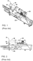
- FIGs. 1 and 2 there are prior art illustrations of an M240 machine gun. Specifically, this includes receiver 218, and its prior art top cover with optic 474. Also illustrated is handle assembly 79 which includes handle 80 and handle connector 82 with handle lift catch 84. Handle 80 is in a fixed position relative to handle connector 82. Generally, handle 80 is oriented in the vicinity of the right side of the M240 machine gun's receiver when the machine gun is intended to be fired. The handle assembly can be rotated upward relative to the receiver when the barrel assembly is to be removed. Additionally, the handle in the upward position, can also be considered a carry position for some embodiments of the M240 machine gun.
- the optic may interfere with the rotational movement of the handle. This may be disadvantageous as one might have to remove the optic first, prior to removing the barrel assembly if such optic was in the necessary rotational path of the handle. Even if there was not a direct mechanical interference between the handle assembly, such close proximity of the handle and optic could complicate the removal of the barrel assembly from the machine gun. Alternatively, the handle would force the optic to be mounted more proximally so that necessary space would be available for the handle to rotate.
- a handle assembly 479 includes handle 480 and handle connector 482. Furthermore, handle 480 includes both connected end 481 and free end 483. Connected end 481 of handle 480 is the end of handle 480 in connection with handle connector 482 whereas free end 483 of handle 480 is not connected to handle connector 482.
- handle 480 may rotate at connected end 481. In doing so, handle 480 may be optionally oriented so as to minimize interference with optic 474 as mounted to an attachment interface of the top cover.
- handle assembly 479 allows for accessories, such as optic 474, to be mounted farther distally forward on the top cover as handle 480 can rotate out of the way of optic 474 in comparison to prior art handle 80.
- Handle 480 may be operable between a variety of positions. Handle 480 may be positioned in a first position with free end 483 of handle 480 pointing proximally. Handle 480 may also be positioned in a second position with free end 483 of handle 480 pointing distally. To assist in clarifying the direction free end 483 of handle 480 points, one can consider the direction linear axis 480LA of handle 480 extends. Linear axis 480LA runs lengthwise, beginning at the centre of connected end 481 and through handle 480, and out through the centre of free end 483. Fig. 5 illustrates free end 483 of handle 480 pointing distally with linear axis 480LA and Fig. 6 illustrates free end 483 of handle 480 pointing proximally with linear axis 480LA.
- free end 483 and linear axis 480LA can be oriented to point toward barrel axis 414BA of barrel 414.
- a barrel axis is the axis running though and parallel with the bore of the barrel, and can be used interchangeably with the axis of the bore.
- handle assembly 479 with handle 480 positioned with free end 483 pointing distally with linear axis 480LA oriented to intersect barrel axis 414BA.
- free end 483 and linear axis 480LA can be oriented to point away from barrel axis 414BA while still pointing distally.
- free end 483 and linear axis 480LA can be oriented to be parallel with barrel 414 and barrel axis 414BA.
- handle assembly 479 with a handle 480 positioned with free end 483 pointing proximally with linear axis 480LA intersecting barrel axis 414BA extending out of the proximal end of the barrel.
- free end 483 and linear axis 480LA can be oriented to point away from barrel axis 414BA while still pointing proximally. Such would occur if handle 480 was pointed slightly upward relative to an attached receiver so that free end 483 and linear axis 480LA pointed slightly upward, but still in a proximal direction.
- free end 483 and linear axis 480LA can be oriented to be parallel with barrel axis 414BA. This is illustrated in Fig. 6 .
- the described orientations are as one of skill in the art would understand such arrangements in visually observing the various components.
- handle 480 is positioned so that free end 483 points distally and toward barrel 414.
- free end 483 of handle 480 points distally where linear axis 480LA would intersect barrel axis 414BA (axes are not shown in Figs. 3 and 4 )
- such orientation of handle 483 can be advantageous for the user.
- the muzzle of the barrel would point more upward than parallel to the ground.
- FIG. 5 illustrates handle assembly 479 with handle 480 having its free end 483 pointing distally
- Fig. 6 illustrates handle assembly 479 with handle 480 having its free end 483 pointing proximally.
- the receiver and other components have been removed to more clearly illustrate handle assembly 479 and different positions of handle 480.
- these two figures also illustrate handle connector 482, lift catch 484 and push button 486.
- Push button 486 can be used to rotate handle 480 of handle assembly 479 from pointing distally as illustrated in Fig. 5 to Fig. 6 wherein free end 483 of handle 480 points proximally.
- handle 480 of handle assembly 479 can fold forward or rearward.
- push button 486 is engaged by the user.
- Lift catch 484 is used to unlock and rotate handle assembly 479 from a carry position to a position wherein handle 480 is in the vicinity of the right side of the receiver.
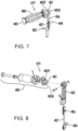
- FIGs. 7 and 8 there are illustrations of a cut-away view of handle assembly 479 and an exploded view of handle assembly 479.
- spring 487 is visible which applies tension to push button 486 to engage notches 485P and 485D on handle 480.
- handle 480 includes two notches 485P and 485D, each notch corresponding to a position of handle 480.
- Fig. 7 illustrates push button 486 engaging notch 485D corresponding to handle 480 having free end 483 pointing distally if handle assembly 479 was configured on a barrel. Engaging notch 485P with push button 486 would result in handle 480 having its free end 483 pointing proximally.
- Fig. 8 provides for further visuals as to how handle assembly 479 is assembled.
- handle 480 rotates at connected end 481 about handle connector 482 so long as push button 486 is engaged to withdraw it from either of notches 485D and 485P of handle 480.
- lesser or greater numbers of notches may be present which would correspond to different orientations of handle 480.
Landscapes
- Engineering & Computer Science (AREA)
- General Engineering & Computer Science (AREA)
- Physics & Mathematics (AREA)
- Optics & Photonics (AREA)
- Toys (AREA)
Claims (5)
- Laufbaugruppe für M240-Maschinengewehr, umfassend:einen Lauf (414) mit einem distalen Ende und einem proximalen Ende und einer Seele; wobei der Lauf eine Laufachse aufweist, die sich durch das distale Ende und das proximale Ende des Laufs und parallel mit der Seele erstreckt; undeine Griffbaugruppe (479) mit einem Griff (480) und einem Griffverbinder (482),wobei der Griffverbinder (482) zum Verbinden der Griffbaugruppe (479) mit dem Lauf (414) ist, wobei der Griff (480) ein freies Ende (483) und ein verbundenes Ende (481) aufweist, wobei das verbundene Ende (481) bedienbar mit dem Griffverbinder (482) verbunden ist und das freie Ende (483) nicht mit dem Griffverbinder (482) verbunden ist, und der Griff weiterhin eine lineare Achse (480LA) aufweist, die an dem verbundenen Ende (481) beginnt und sich durch den Griff (480) und aus einer Mitte des freien Endes (483) des Griffs (480) erstreckt,dadurch gekennzeichnet, dass der Griff (480) zwischen einer ersten Position, wobei das freie Ende (483) des Griffs (480) proximal weist, und einer zweiten Position, wobei das freie Ende (483) der Griffbaugruppe (480) distal weist, bedienbar ist.
- Laufbaugruppe für M240-Maschinengewehr nach Anspruch 1, wobei: (i) in der ersten Position das freie Ende (483) des Griffs (480) proximal weist, wobei die lineare Achse (480LA) des Griffs (480) etwa parallel zu der Laufachse (414BA) ausgerichtet ist; oder
ii) in der zweiten Position das freie Ende (483) des Griffs (480) distal weist, wobei die lineare Achse (480LA) des Griffs (480) etwa parallel zu der Laufachse (414BA) ausgerichtet ist. - Laufbaugruppe für M240-Maschinengewehr nach Anspruch 1, wobei i) in der zweiten Position das freie Ende (483) des Griffs (480) distal weist, wobei die lineare Achse (480LA) des Griffs (480) von der Laufachse (414BA) weg ausgerichtet ist; oder
ii) in der zweiten Position das freie Ende (483) des Griffs (480) distal weist, wobei die lineare Achse (480LA) des Griffs (480) ausgerichtet ist, um sich mit der Laufachse (414BA) zu überschneiden. - Laufbaugruppe für M240-Maschinengewehr nach Anspruch 1, 2 oder 3, weiterhin umfassend einen Druckknopf (486), um zwischen der ersten Position und der zweiten Position des Griffs (480) bedienbar auszuwählen.
- Laufbaugruppe für M240-Maschinengewehr nach Anspruch 4, wobei die Griffbaugruppe (479) weiterhin eine erste Kerbe (485P), um den Druckknopf (486) in Eingriff zu nehmen, um den Griff (480) in der ersten Position auszurichten, und eine zweite Kerbe (485D), um den Druckknopf (486) in Eingriff zu nehmen, um den Griff (480) in der zweiten Position auszurichten, umfasst.
Applications Claiming Priority (2)
| Application Number | Priority Date | Filing Date | Title |
|---|---|---|---|
| US14/823,110 US10006727B2 (en) | 2014-08-11 | 2015-08-11 | Firearm system |
| PCT/US2016/025294 WO2017027072A1 (en) | 2014-08-11 | 2016-03-31 | Firearm system |
Publications (4)
| Publication Number | Publication Date |
|---|---|
| EP3334996A1 EP3334996A1 (de) | 2018-06-20 |
| EP3334996A4 EP3334996A4 (de) | 2019-07-17 |
| EP3334996C0 EP3334996C0 (de) | 2023-08-16 |
| EP3334996B1 true EP3334996B1 (de) | 2023-08-16 |
Family
ID=62143731
Family Applications (1)
| Application Number | Title | Priority Date | Filing Date |
|---|---|---|---|
| EP16835557.6A Active EP3334996B1 (de) | 2015-08-11 | 2016-03-31 | Laufbaugruppe für m240 maschinengewehr |
Country Status (1)
| Country | Link |
|---|---|
| EP (1) | EP3334996B1 (de) |
Family Cites Families (6)
| Publication number | Priority date | Publication date | Assignee | Title |
|---|---|---|---|---|
| US2131716A (en) * | 1937-01-14 | 1938-09-27 | J M & M S Browning Company | Detachable barrel construction for firearms |
| US4651455A (en) * | 1985-06-21 | 1987-03-24 | Geiser Jr John D | Bolt action rifle |
| EP1592941B1 (de) * | 2003-01-28 | 2008-08-13 | Corner Shot Holdings, L.L.C. | Handgriff für schusswaffe |
| DE102004007916A1 (de) * | 2004-02-18 | 2005-09-15 | Heckler & Koch Gmbh | Waffe mit Montageschiene |
| US20120144985A1 (en) * | 2007-06-22 | 2012-06-14 | Fn Manufacturing Llc | Light Weight Machine Gun |
| US20150020429A1 (en) * | 2013-07-18 | 2015-01-22 | Dale J. Savoy | Rail Extension Device |
-
2016
- 2016-03-31 EP EP16835557.6A patent/EP3334996B1/de active Active
Also Published As
| Publication number | Publication date |
|---|---|
| EP3334996C0 (de) | 2023-08-16 |
| EP3334996A1 (de) | 2018-06-20 |
| EP3334996A4 (de) | 2019-07-17 |
Similar Documents
| Publication | Publication Date | Title |
|---|---|---|
| US10718579B2 (en) | Machine gun barrel assembly | |
| US8397414B2 (en) | Buttstock pre-adjustment block | |
| US9541339B2 (en) | Ambidextrously operable firearm receiver assembly | |
| US10184744B2 (en) | Quick connect for pistol suppressor | |
| WO2017027072A1 (en) | Firearm system | |
| US8333139B2 (en) | System for attaching or detaching firearm accessories using a cartridge case and rim channel | |
| US9015980B2 (en) | Folding grip for a firearm | |
| US8393107B2 (en) | Firearm assembly including a first weapon and a second weapon selectively mounted to the first weapon | |
| US8333028B1 (en) | Firearm mode selection mechanism | |
| US20170122684A1 (en) | Bolt action chassis for rifles, shotguns, and muzzle loaders | |
| US20210180897A1 (en) | Pivot pin | |
| US9297600B1 (en) | Firearm choke tube | |
| US9772160B2 (en) | Firearm maintenance tool | |
| US20180142979A1 (en) | Firearm fire selector control device | |
| US20150345885A1 (en) | Apparatus and Method Requiring Disassembly of Rifle to Remove Magazine | |
| US20200378700A1 (en) | Handgun with a locking device | |
| US6968642B1 (en) | Close combat handguard for rifles | |
| US20180128561A1 (en) | Resetting magazine cut-off for firearms | |
| US9658009B1 (en) | Bolt handle modification system and method | |
| US11079190B2 (en) | Firearms recoil spring insert and recoil spring insert assembly | |
| US20200011627A1 (en) | Firearm safety interlock | |
| US20250109925A1 (en) | Firearm conversion jig and method of using the same | |
| EP3334996A1 (de) | Schusswaffensystem | |
| WO2017173225A1 (en) | Firearm system | |
| TWI548858B (zh) | 可改裝的自動或半自動來福槍 |
Legal Events
| Date | Code | Title | Description |
|---|---|---|---|
| STAA | Information on the status of an ep patent application or granted ep patent |
Free format text: STATUS: THE INTERNATIONAL PUBLICATION HAS BEEN MADE |
|
| PUAI | Public reference made under article 153(3) epc to a published international application that has entered the european phase |
Free format text: ORIGINAL CODE: 0009012 |
|
| STAA | Information on the status of an ep patent application or granted ep patent |
Free format text: STATUS: REQUEST FOR EXAMINATION WAS MADE |
|
| 17P | Request for examination filed |
Effective date: 20180312 |
|
| AK | Designated contracting states |
Kind code of ref document: A1 Designated state(s): AL AT BE BG CH CY CZ DE DK EE ES FI FR GB GR HR HU IE IS IT LI LT LU LV MC MK MT NL NO PL PT RO RS SE SI SK SM TR |
|
| AX | Request for extension of the european patent |
Extension state: BA ME |
|
| DAV | Request for validation of the european patent (deleted) | ||
| DAX | Request for extension of the european patent (deleted) | ||
| RIC1 | Information provided on ipc code assigned before grant |
Ipc: F41A 11/02 20060101ALN20190214BHEP Ipc: F41A 21/48 20060101ALI20190214BHEP Ipc: F41C 23/20 20060101ALI20190214BHEP Ipc: F41A 3/40 20060101ALI20190214BHEP Ipc: F41G 1/16 20060101ALI20190214BHEP Ipc: F41A 3/66 20060101AFI20190214BHEP Ipc: F41A 5/26 20060101ALI20190214BHEP Ipc: F41A 19/10 20060101ALN20190214BHEP Ipc: F41A 21/00 20060101ALI20190214BHEP |
|
| RIC1 | Information provided on ipc code assigned before grant |
Ipc: F41A 5/26 20060101ALI20190516BHEP Ipc: F41A 19/10 20060101ALN20190516BHEP Ipc: F41G 1/16 20060101ALI20190516BHEP Ipc: F41A 3/66 20060101AFI20190516BHEP Ipc: F41A 11/02 20060101ALN20190516BHEP Ipc: F41A 21/00 20060101ALI20190516BHEP Ipc: F41C 23/20 20060101ALI20190516BHEP Ipc: F41A 21/48 20060101ALI20190516BHEP Ipc: F41A 3/40 20060101ALI20190516BHEP |
|
| A4 | Supplementary search report drawn up and despatched |
Effective date: 20190617 |
|
| RIC1 | Information provided on ipc code assigned before grant |
Ipc: F41A 3/66 20060101AFI20190611BHEP Ipc: F41A 11/02 20060101ALN20190611BHEP Ipc: F41C 33/08 20060101ALI20190611BHEP Ipc: F41A 21/00 20060101ALI20190611BHEP Ipc: F41A 19/10 20060101ALN20190611BHEP Ipc: F41G 1/16 20060101ALI20190611BHEP Ipc: F41A 21/48 20060101ALI20190611BHEP Ipc: F41A 3/40 20060101ALI20190611BHEP Ipc: F41A 5/26 20060101ALI20190611BHEP Ipc: F41C 23/20 20060101ALI20190611BHEP |
|
| RAP1 | Party data changed (applicant data changed or rights of an application transferred) |
Owner name: WHG PROPERTIES, LLC |
|
| RIN1 | Information on inventor provided before grant (corrected) |
Inventor name: BARRETT, RONNIE Inventor name: BARRETT, CHRISTOPHER GENE |
|
| GRAP | Despatch of communication of intention to grant a patent |
Free format text: ORIGINAL CODE: EPIDOSNIGR1 |
|
| STAA | Information on the status of an ep patent application or granted ep patent |
Free format text: STATUS: GRANT OF PATENT IS INTENDED |
|
| RIC1 | Information provided on ipc code assigned before grant |
Ipc: F41A 11/02 20060101ALN20220216BHEP Ipc: F41A 19/10 20060101ALN20220216BHEP Ipc: F41C 33/08 20060101ALI20220216BHEP Ipc: F41G 1/16 20060101ALI20220216BHEP Ipc: F41A 21/48 20060101ALI20220216BHEP Ipc: F41A 5/26 20060101ALI20220216BHEP Ipc: F41A 3/40 20060101ALI20220216BHEP Ipc: F41C 23/20 20060101ALI20220216BHEP Ipc: F41A 21/00 20060101ALI20220216BHEP Ipc: F41A 3/66 20060101AFI20220216BHEP |
|
| RIC1 | Information provided on ipc code assigned before grant |
Ipc: F41A 11/02 20060101ALN20220225BHEP Ipc: F41A 19/10 20060101ALN20220225BHEP Ipc: F41C 33/08 20060101ALI20220225BHEP Ipc: F41G 1/16 20060101ALI20220225BHEP Ipc: F41A 21/48 20060101ALI20220225BHEP Ipc: F41A 5/26 20060101ALI20220225BHEP Ipc: F41A 3/40 20060101ALI20220225BHEP Ipc: F41C 23/20 20060101ALI20220225BHEP Ipc: F41A 21/00 20060101ALI20220225BHEP Ipc: F41A 3/66 20060101AFI20220225BHEP |
|
| INTG | Intention to grant announced |
Effective date: 20220322 |
|
| GRAJ | Information related to disapproval of communication of intention to grant by the applicant or resumption of examination proceedings by the epo deleted |
Free format text: ORIGINAL CODE: EPIDOSDIGR1 |
|
| STAA | Information on the status of an ep patent application or granted ep patent |
Free format text: STATUS: REQUEST FOR EXAMINATION WAS MADE |
|
| GRAP | Despatch of communication of intention to grant a patent |
Free format text: ORIGINAL CODE: EPIDOSNIGR1 |
|
| INTC | Intention to grant announced (deleted) | ||
| STAA | Information on the status of an ep patent application or granted ep patent |
Free format text: STATUS: GRANT OF PATENT IS INTENDED |
|
| RIC1 | Information provided on ipc code assigned before grant |
Ipc: F41A 11/02 20060101ALN20220718BHEP Ipc: F41A 19/10 20060101ALN20220718BHEP Ipc: F41C 33/08 20060101ALI20220718BHEP Ipc: F41G 1/16 20060101ALI20220718BHEP Ipc: F41A 21/48 20060101ALI20220718BHEP Ipc: F41A 5/26 20060101ALI20220718BHEP Ipc: F41A 3/40 20060101ALI20220718BHEP Ipc: F41C 23/20 20060101ALI20220718BHEP Ipc: F41A 21/00 20060101ALI20220718BHEP Ipc: F41A 3/66 20060101AFI20220718BHEP |
|
| INTG | Intention to grant announced |
Effective date: 20220811 |
|
| GRAS | Grant fee paid |
Free format text: ORIGINAL CODE: EPIDOSNIGR3 |
|
| GRAA | (expected) grant |
Free format text: ORIGINAL CODE: 0009210 |
|
| STAA | Information on the status of an ep patent application or granted ep patent |
Free format text: STATUS: THE PATENT HAS BEEN GRANTED |
|
| AK | Designated contracting states |
Kind code of ref document: B1 Designated state(s): AL AT BE BG CH CY CZ DE DK EE ES FI FR GB GR HR HU IE IS IT LI LT LU LV MC MK MT NL NO PL PT RO RS SE SI SK SM TR |
|
| REG | Reference to a national code |
Ref country code: GB Ref legal event code: FG4D |
|
| REG | Reference to a national code |
Ref country code: CH Ref legal event code: EP Ref country code: DE Ref legal event code: R096 Ref document number: 602016082010 Country of ref document: DE |
|
| REG | Reference to a national code |
Ref country code: IE Ref legal event code: FG4D |
|
| U01 | Request for unitary effect filed |
Effective date: 20230915 |
|
| U07 | Unitary effect registered |
Designated state(s): AT BE BG DE DK EE FI FR IT LT LU LV MT NL PT SE SI Effective date: 20230922 |
|
| PG25 | Lapsed in a contracting state [announced via postgrant information from national office to epo] |
Ref country code: GR Free format text: LAPSE BECAUSE OF FAILURE TO SUBMIT A TRANSLATION OF THE DESCRIPTION OR TO PAY THE FEE WITHIN THE PRESCRIBED TIME-LIMIT Effective date: 20231117 |
|
| PG25 | Lapsed in a contracting state [announced via postgrant information from national office to epo] |
Ref country code: IS Free format text: LAPSE BECAUSE OF FAILURE TO SUBMIT A TRANSLATION OF THE DESCRIPTION OR TO PAY THE FEE WITHIN THE PRESCRIBED TIME-LIMIT Effective date: 20231216 |
|
| PG25 | Lapsed in a contracting state [announced via postgrant information from national office to epo] |
Ref country code: RS Free format text: LAPSE BECAUSE OF FAILURE TO SUBMIT A TRANSLATION OF THE DESCRIPTION OR TO PAY THE FEE WITHIN THE PRESCRIBED TIME-LIMIT Effective date: 20230816 Ref country code: NO Free format text: LAPSE BECAUSE OF FAILURE TO SUBMIT A TRANSLATION OF THE DESCRIPTION OR TO PAY THE FEE WITHIN THE PRESCRIBED TIME-LIMIT Effective date: 20231116 Ref country code: IS Free format text: LAPSE BECAUSE OF FAILURE TO SUBMIT A TRANSLATION OF THE DESCRIPTION OR TO PAY THE FEE WITHIN THE PRESCRIBED TIME-LIMIT Effective date: 20231216 Ref country code: HR Free format text: LAPSE BECAUSE OF FAILURE TO SUBMIT A TRANSLATION OF THE DESCRIPTION OR TO PAY THE FEE WITHIN THE PRESCRIBED TIME-LIMIT Effective date: 20230816 Ref country code: GR Free format text: LAPSE BECAUSE OF FAILURE TO SUBMIT A TRANSLATION OF THE DESCRIPTION OR TO PAY THE FEE WITHIN THE PRESCRIBED TIME-LIMIT Effective date: 20231117 |
|
| PG25 | Lapsed in a contracting state [announced via postgrant information from national office to epo] |
Ref country code: PL Free format text: LAPSE BECAUSE OF FAILURE TO SUBMIT A TRANSLATION OF THE DESCRIPTION OR TO PAY THE FEE WITHIN THE PRESCRIBED TIME-LIMIT Effective date: 20230816 |
|
| U20 | Renewal fee for the european patent with unitary effect paid |
Year of fee payment: 9 Effective date: 20240207 |
|
| PG25 | Lapsed in a contracting state [announced via postgrant information from national office to epo] |
Ref country code: ES Free format text: LAPSE BECAUSE OF FAILURE TO SUBMIT A TRANSLATION OF THE DESCRIPTION OR TO PAY THE FEE WITHIN THE PRESCRIBED TIME-LIMIT Effective date: 20230816 |
|
| PG25 | Lapsed in a contracting state [announced via postgrant information from national office to epo] |
Ref country code: SM Free format text: LAPSE BECAUSE OF FAILURE TO SUBMIT A TRANSLATION OF THE DESCRIPTION OR TO PAY THE FEE WITHIN THE PRESCRIBED TIME-LIMIT Effective date: 20230816 Ref country code: RO Free format text: LAPSE BECAUSE OF FAILURE TO SUBMIT A TRANSLATION OF THE DESCRIPTION OR TO PAY THE FEE WITHIN THE PRESCRIBED TIME-LIMIT Effective date: 20230816 Ref country code: ES Free format text: LAPSE BECAUSE OF FAILURE TO SUBMIT A TRANSLATION OF THE DESCRIPTION OR TO PAY THE FEE WITHIN THE PRESCRIBED TIME-LIMIT Effective date: 20230816 Ref country code: CZ Free format text: LAPSE BECAUSE OF FAILURE TO SUBMIT A TRANSLATION OF THE DESCRIPTION OR TO PAY THE FEE WITHIN THE PRESCRIBED TIME-LIMIT Effective date: 20230816 Ref country code: SK Free format text: LAPSE BECAUSE OF FAILURE TO SUBMIT A TRANSLATION OF THE DESCRIPTION OR TO PAY THE FEE WITHIN THE PRESCRIBED TIME-LIMIT Effective date: 20230816 |
|
| REG | Reference to a national code |
Ref country code: DE Ref legal event code: R097 Ref document number: 602016082010 Country of ref document: DE |
|
| PLBE | No opposition filed within time limit |
Free format text: ORIGINAL CODE: 0009261 |
|
| STAA | Information on the status of an ep patent application or granted ep patent |
Free format text: STATUS: NO OPPOSITION FILED WITHIN TIME LIMIT |
|
| 26N | No opposition filed |
Effective date: 20240517 |
|
| REG | Reference to a national code |
Ref country code: CH Ref legal event code: PL |
|
| PG25 | Lapsed in a contracting state [announced via postgrant information from national office to epo] |
Ref country code: MC Free format text: LAPSE BECAUSE OF FAILURE TO SUBMIT A TRANSLATION OF THE DESCRIPTION OR TO PAY THE FEE WITHIN THE PRESCRIBED TIME-LIMIT Effective date: 20230816 |
|
| PG25 | Lapsed in a contracting state [announced via postgrant information from national office to epo] |
Ref country code: MC Free format text: LAPSE BECAUSE OF FAILURE TO SUBMIT A TRANSLATION OF THE DESCRIPTION OR TO PAY THE FEE WITHIN THE PRESCRIBED TIME-LIMIT Effective date: 20230816 |
|
| PG25 | Lapsed in a contracting state [announced via postgrant information from national office to epo] |
Ref country code: IE Free format text: LAPSE BECAUSE OF NON-PAYMENT OF DUE FEES Effective date: 20240331 |
|
| PG25 | Lapsed in a contracting state [announced via postgrant information from national office to epo] |
Ref country code: IE Free format text: LAPSE BECAUSE OF NON-PAYMENT OF DUE FEES Effective date: 20240331 Ref country code: CH Free format text: LAPSE BECAUSE OF NON-PAYMENT OF DUE FEES Effective date: 20240331 |
|
| U20 | Renewal fee for the european patent with unitary effect paid |
Year of fee payment: 10 Effective date: 20250205 |
|
| PG25 | Lapsed in a contracting state [announced via postgrant information from national office to epo] |
Ref country code: CY Free format text: LAPSE BECAUSE OF FAILURE TO SUBMIT A TRANSLATION OF THE DESCRIPTION OR TO PAY THE FEE WITHIN THE PRESCRIBED TIME-LIMIT; INVALID AB INITIO Effective date: 20160331 |
|
| PG25 | Lapsed in a contracting state [announced via postgrant information from national office to epo] |
Ref country code: HU Free format text: LAPSE BECAUSE OF FAILURE TO SUBMIT A TRANSLATION OF THE DESCRIPTION OR TO PAY THE FEE WITHIN THE PRESCRIBED TIME-LIMIT; INVALID AB INITIO Effective date: 20160331 |
|
| PG25 | Lapsed in a contracting state [announced via postgrant information from national office to epo] |
Ref country code: TR Free format text: LAPSE BECAUSE OF FAILURE TO SUBMIT A TRANSLATION OF THE DESCRIPTION OR TO PAY THE FEE WITHIN THE PRESCRIBED TIME-LIMIT Effective date: 20230816 |
|
| U20 | Renewal fee for the european patent with unitary effect paid |
Year of fee payment: 11 Effective date: 20260209 |
|
| PGFP | Annual fee paid to national office [announced via postgrant information from national office to epo] |
Ref country code: GB Payment date: 20260209 Year of fee payment: 11 |