EP3334997B1 - Polarisationsfilterung für selbstemission von fenstern durch aerothermische heizung - Google Patents
Polarisationsfilterung für selbstemission von fenstern durch aerothermische heizung Download PDFInfo
- Publication number
- EP3334997B1 EP3334997B1 EP16840301.2A EP16840301A EP3334997B1 EP 3334997 B1 EP3334997 B1 EP 3334997B1 EP 16840301 A EP16840301 A EP 16840301A EP 3334997 B1 EP3334997 B1 EP 3334997B1
- Authority
- EP
- European Patent Office
- Prior art keywords
- polarizer
- polarization
- array
- microgrid
- filter
- Prior art date
- Legal status (The legal status is an assumption and is not a legal conclusion. Google has not performed a legal analysis and makes no representation as to the accuracy of the status listed.)
- Active
Links
Images





Classifications
-
- G—PHYSICS
- G01—MEASURING; TESTING
- G01J—MEASUREMENT OF INTENSITY, VELOCITY, SPECTRAL CONTENT, POLARISATION, PHASE OR PULSE CHARACTERISTICS OF INFRARED, VISIBLE OR ULTRAVIOLET LIGHT; COLORIMETRY; RADIATION PYROMETRY
- G01J1/00—Photometry, e.g. photographic exposure meter
- G01J1/02—Details
- G01J1/04—Optical or mechanical part supplementary adjustable parts
- G01J1/0407—Optical elements not provided otherwise, e.g. manifolds, windows, holograms, gratings
- G01J1/0429—Optical elements not provided otherwise, e.g. manifolds, windows, holograms, gratings using polarisation elements
-
- B—PERFORMING OPERATIONS; TRANSPORTING
- B64—AIRCRAFT; AVIATION; COSMONAUTICS
- B64C—AEROPLANES; HELICOPTERS
- B64C1/00—Fuselages; Constructional features common to fuselages, wings, stabilising surfaces or the like
- B64C1/14—Windows; Doors; Hatch covers or access panels; Surrounding frame structures; Canopies; Windscreens accessories therefor, e.g. pressure sensors, water deflectors, hinges, seals, handles, latches, windscreen wipers
- B64C1/1476—Canopies; Windscreens or similar transparent elements
- B64C1/1484—Windows
-
- F—MECHANICAL ENGINEERING; LIGHTING; HEATING; WEAPONS; BLASTING
- F41—WEAPONS
- F41G—WEAPON SIGHTS; AIMING
- F41G7/00—Direction control systems for self-propelled missiles
- F41G7/20—Direction control systems for self-propelled missiles based on continuous observation of target position
- F41G7/22—Homing guidance systems
- F41G7/2253—Passive homing systems, i.e. comprising a receiver and do not requiring an active illumination of the target
-
- F—MECHANICAL ENGINEERING; LIGHTING; HEATING; WEAPONS; BLASTING
- F41—WEAPONS
- F41G—WEAPON SIGHTS; AIMING
- F41G7/00—Direction control systems for self-propelled missiles
- F41G7/20—Direction control systems for self-propelled missiles based on continuous observation of target position
- F41G7/22—Homing guidance systems
- F41G7/2273—Homing guidance systems characterised by the type of waves
- F41G7/2293—Homing guidance systems characterised by the type of waves using electromagnetic waves other than radio waves
-
- F—MECHANICAL ENGINEERING; LIGHTING; HEATING; WEAPONS; BLASTING
- F42—AMMUNITION; BLASTING
- F42B—EXPLOSIVE CHARGES, e.g. FOR BLASTING, FIREWORKS, AMMUNITION
- F42B10/00—Means for influencing, e.g. improving, the aerodynamic properties of projectiles or missiles; Arrangements on projectiles or missiles for stabilising, steering, range-reducing, range-increasing or fall-retarding
- F42B10/32—Range-reducing or range-increasing arrangements; Fall-retarding means
- F42B10/38—Range-increasing arrangements
- F42B10/42—Streamlined projectiles
- F42B10/46—Streamlined nose cones; Windshields; Radomes
-
- F—MECHANICAL ENGINEERING; LIGHTING; HEATING; WEAPONS; BLASTING
- F42—AMMUNITION; BLASTING
- F42B—EXPLOSIVE CHARGES, e.g. FOR BLASTING, FIREWORKS, AMMUNITION
- F42B15/00—Self-propelled projectiles or missiles, e.g. rockets; Guided missiles
- F42B15/08—Self-propelled projectiles or missiles, e.g. rockets; Guided missiles for carrying measuring instruments; Arrangements for mounting sensitive cargo within a projectile; Arrangements for acoustic sensitive cargo within a projectile
-
- F—MECHANICAL ENGINEERING; LIGHTING; HEATING; WEAPONS; BLASTING
- F42—AMMUNITION; BLASTING
- F42B—EXPLOSIVE CHARGES, e.g. FOR BLASTING, FIREWORKS, AMMUNITION
- F42B15/00—Self-propelled projectiles or missiles, e.g. rockets; Guided missiles
- F42B15/34—Protection against overheating or radiation, e.g. heat shields; Additional cooling arrangements
-
- G—PHYSICS
- G01—MEASURING; TESTING
- G01S—RADIO DIRECTION-FINDING; RADIO NAVIGATION; DETERMINING DISTANCE OR VELOCITY BY USE OF RADIO WAVES; LOCATING OR PRESENCE-DETECTING BY USE OF THE REFLECTION OR RERADIATION OF RADIO WAVES; ANALOGOUS ARRANGEMENTS USING OTHER WAVES
- G01S3/00—Direction-finders for determining the direction from which infrasonic, sonic, ultrasonic or electromagnetic waves, or particle emission, not having a directional significance, are being received
- G01S3/78—Direction-finders for determining the direction from which infrasonic, sonic, ultrasonic or electromagnetic waves, or particle emission, not having a directional significance, are being received using electromagnetic waves other than radio waves
- G01S3/781—Details
Definitions
- This invention relates to optical systems, as defined in the claims, for use with flight vehicles subject to extreme aero-thermal heating in which window self-emission reduces the signal-to-noise ratio (SNR) of sensed target emissions complicating the task of target tracking.
- SNR signal-to-noise ratio
- Optical systems for use with flight vehicles such as guided missiles or belly-mounted sensor pods on aircraft typically include an optical window (e.g., a dome) that protects the sensitive optical and electrical components.
- the optical window is transparent in a desired spectral band (e.g., the MWIR band from 3-5 microns) to pass emissions from a target in a scene through the optical window to the entrance pupil of focusing optics, which in turn route the incident radiation along an optical path and focus the radiation onto a detector.
- the detector may, for example, be a quad-cell detector for non-imaging applications such as spot tracking.
- the detector may, for example, be a focal plane array (FPA) for various imaging applications.
- FPA focal plane array
- the FPA generally includes an array of pixels, each pixel including a photo-detector that generates a signal responsive to the intensity of the incident. These signals are collected and combined to form a digital image of the object.
- the focusing optics may be fixed or gimbaled to increase the field-of-regard (FOR).
- FOR field-of-regard
- the entrance pupil is symmetric about the central axis of symmetry of the optical window. Alternately, the entrance pupil may be offset such that the FOR does not cross the tip of the optical window to reduce distortion (See U.S. Pub. No. 2015/0022874 ).
- the only emissions sensed by the detector are those from the scene and particularly a specified target.
- sources of parasitic radiation or "noise” that reduces the SNR of the target and the ability of the guidance unit to track the target.
- One such source is the self-emission of the optical window that may occur due to aero-thermal heating as the missile or pod travels through the atmosphere.
- the amount of aero-thermal heating depends on the flight speeds, aerodynamic design of the window that induces heating and the thermal design of the window that removes heat to cool the window.
- the window self-emissions can raise the general background noise or can induce a gradient in the detected signal (due to non-uniform heating of the window). In many instances, the self-emissions due to aero-thermal heating are insignificant. In others, it is desirable to try to mitigate the effects of window self-emissions.
- One approach is to spectrally filter the incident radiation.
- the temperature of the aero-thermally heated optical window is much higher than the temperature of the target.
- the emissions of the target and the optical window will have different spectral characteristics.
- the relative intensity of the window emissions will be stronger at the longer wavelengths in the MWIR band.
- Low-pass filtering the incident radiation can improve the contrast of the target radiation (signal) to the window self-emitted radiation (noise). See, for example, U.S. Patent No. 8,466,964 entitled “Multispectral Uncooled Thermal Infrared Camera System” issued June 18, 2014 .
- Non-uniform aero-thermal heating can induce a gradient in the window self-emissions, hence the total detected incident radiation.
- This gradient is a form of "fixed-pattern noise".
- One way to remove this fixed pattern noise is by using Scene based Non-Uniformity Correction (NUC), in which the scene is intentionally blurred and the resulting image is recorded and then subtracted from non-blurred images of the scene.
- NUC Scene based Non-Uniformity Correction
- the blurring is usually done by moving an optical element, such as a lens, prism, or diffuser, into the beam, though some scene-based NUCing methods are completely software-based.
- Polarimeters can be used to analyze the polarization components of light to, for example, extract shape information from an object. Some polarimeters use two or more linear polarizers (polarized pixels) that filter at least half of the incoming light and direct the remaining light to a focal plane. As a result, the brightness of the image at the focal plane is substantially reduced (e.g., by about half).
- Polarimetry requires at least three measurements to analyze the polarization components of light; at least two different polarization components and possibly an unpolarized component.
- the pixelated filter array, and FPA are divided into groups of four pixels (e.g., a 2 ⁇ 2 sub-array of pixels).
- the electronics may compute an Angle of Linear Polarization (AoLP) image and a Degree of Linear Polarization (DoLP) image from the four linearly polarized pixel values in each grouping to extract shape information.
- the electronics may also compute an average of the four detector pixels in each grouping to form a reduced resolution intensity image.
- US 5135183 A relates to a birefringent prism that is disposed in front of the entrance aperture of a Cassegrain-type telescope which constitutes the optical focussing assembly in a tracking system for a guided missile or the like.
- the prism refracts first radiation having a first polarization in a first direction, and refracts second radiation having a second polarization which is orthogonal to the first polarization in a second direction which is deviated from the first direction by a predetermined angle.
- US 2010/127174 A1 relates to a multi-mode detector and detection method that utilize shared optical components to detect multiple different incoming wavelengths of energy.
- US 2014/063299 A1 relates to an optical imaging system and method including a movable pixelated filter array, a shutter mechanism to which the pixelated filter array is attached, and a controller configured to implement a data reduction algorithm.
- US 2012/111992 A1 relates to a vehicle including electro-optic imaging that has a vehicle body having an outer surface including a front portion and a side portion, wherein the side portion includes a plurality of portholes.
- a propulsion source is within the vehicle body for moving the vehicle.
- US 2015/022874 A1 relates to an offset aperture two-axis gimbaled optical system that comprises a two-axis gimbal and an optics assembly that is mounted on the inner gimbal and offset radially from the rotation axis of the outer gimbal.
- a polarizer is positioned in the optical path between the optical window and a detector (e.g., a FPA or quad-cell).
- the polarizer comprises at least one filter pixel that imparts a linear polarization of a certain angular value to filter the incident radiation as a function of the polarization of the incident radiation. At least one filter pixel is aligned to the P-polarization in the plane of incidence. If the polarizer is a sheet polarizer (effectively one large filter pixel), the sheet polarizer is aligned to the P-polarization in the plane of incidence.
- the polarizer is a microgrid polarizer
- at least one filter pixel and preferably multiple filter pixels in each sub-array are aligned to the P-polarization in the plane of incidence. This improves the SNR of the detected target radiation.
- the AoLP image removes the effects of non-uniform aero-thermal heating.
- the sheet polarizer may be used with imaging or non-imaging detectors whereas the microgrid polarizer is only applicable for imaging detectors such as a FPA.
- the flight vehicle is propelled toward the target at supersonic speeds in excess of Mach 1 and, in some applications, hypersonic speeds in excess of Mach 5.
- a sheet polarizer passes P-polarized radiation thereby modulating the intensity of incident radiation as a function of its P-polarization and increasing a contrast ratio of target radiation to self-emitted radiation.
- the sheet polarizer can be positioned at any point along the optical path between the optical window and the detector.
- the sheet polarizer can be positioned off-gimbal or at any position on the inner gimbal. If off gimbal, the gimbal is rotated to align the plane of incidence to the sheet polarizer to read out the detector signals.
- the sheet polarizer could be a dynamic microgrid array electronically controlled to present a single linear polarization that tracks the rotation of the gimbal. If on-gimbal, the sheet polarizer is mounted in alignment to the P-polarization in the plane of incidence and remains aligned as the gimbal rotates.
- a microgrid polarizer array having a plurality of polarized pixelated filter sub-arrays is positioned at the FPA or an intermediate image (conjugate plane) of the focal plane.
- Each sub-array comprises three or more filter pixels Q of which at least two filter pixels impart a linear polarization of a certain and different angular value.
- the microgrid polarizer is mounted such that at least one of the filter pixels (preferably multiple) in each sub-array is aligned to the P-polarization in the plane of incidence.
- the present invention provides an optical system for use with flight vehicles subject to extreme aero-thermal heating in which window self-emission reduces the SNR of sensed target emissions complicating the task of target tracking.
- Supersonic (> Mach 1) and more so hypersonic (> Mach 5) weapons may produce such extreme aero-thermal heating of the window.
- Spectral filtering techniques may be effective to increase the SNR, however, in some systems, such techniques by themselves are not sufficient.
- the present invention provides a technique based on exploiting the polarization of the target and self-emitted radiation to lower the background window emission or to remove a gradient due to non-uniform heating.
- a hypersonic weapon 10 is subject to extreme aero-thermal heating of its optical window 12 when travelling at hypersonic speeds through the atmosphere.
- the weapon comprises an airframe 15 and a propulsion system 17 such as a liquid or solid rocket motor configured to propel the weapon toward the target in excess of Mach 5.
- the temperature of the optical window is typically much higher than the temperature of a target. Consequently, the level of emissions 14 from optical window 12 is much higher than the level of emissions 16 from the target across the entire MWIR band from 3-5 microns.
- the integrated radiance 18 of the optical window over the MWIR band is several times the integrated radiance 20 of the target.
- light 30 from a distant target 31 passes through both an outer surface 32 and an inner surface 34 of a tilted optical window 36 , representative of an off-axis portion of the hypersonic weapon's optical window.
- the aero-thermal heated window self-emits light in all directions.
- a portion of window light 33 is emitted in the same direction as the incident target light 30 and passes through only inner surface 34.
- a plane of incidence 38 is defined as the plane that contains the incident ray (light 30 ) and a normal 40 to the surface of the window. If the outer and inner surfaces have the same symmetry (as they often do), the planes of incidence of the two surfaces are coincident.
- the Fresnel equations describe the behavior of light when moving between media of differing refractive indices such as between the optical window and air. According to the Fresnel equations, the transverse electric field of light that is p-polarized oscillates in the plane of incidence 38. The electric field of s-polarized light oscillates perpendicular to the plane of incidence. According to the equations, a majority of the incident energy is p-polarized.
- the degree to which the light is p-polarized is most strongly affected by the angle-of-incidence (AOI) 42 between the target light 30 and the surface normal 40 , and to a lesser effect the refractive index difference between window material and air.
- AOI angle-of-incidence
- the p-polarization 44 of the target light is greater than the p-polarization 46 of the window light.
- the p-polarization difference 48 between the two curves increases (to a point) with an increasing AOI. This difference is a result of the target light 30 passing through both the inner and outer surfaces, and thus twice transitioning between the window media and air, and the window light 33 passing through only the inner surface, and thus transitioning between the window media and air only once.
- a typical target gives off a thermal signature in the MWIR band that is a combination of unpolarized and polarized light.
- the tilted window 36 induces a p-polarization bias to the unpolarized component of thermal signal 30 that is stronger than the polarized component of the signal 33. Note this is only true if the entrance pupil of the optical system is positioned to look through an off-axis segment of the window. If the optical system is a more typical on-axis system, the light will not have a predominant p-polarization state because the rotational symmetry of the optical window will cancel the induced polarization.
- the present invention combines an off-axis optical system, fixed or gimbaled, whose entrance pupil looks through an off-axis segment of the optical window with a polarizer that is positioned in the optical path between the optical window and a detector.
- the polarizer comprises at least one filter pixel that imparts a linear polarization of a certain angular value to filter the incident radiation as a function of the polarization of the incident radiation.
- At least one filter pixel is aligned to the P-polarization in the plane of incidence.
- the at least one filter pixel modulates the intensity of incident radiation as a function of its P-polarization. Because the target light is more p-polarized than the window light, this increases a contrast ratio of target light (radiation) to window light (radiation), which increases the SNR at the detector.
- the polarizer is a sheet polarizer (effectively one large filter pixel)
- the sheet polarizer is aligned to the P-polarization in the plane of incidence.
- the sheet polarizer modulates the intensity of incident radiation, both target radiation and self-emitted radiation, as a function of its P-polarization. This increases the contrast ratio of target radiation to self-emitted radiation, hence the SNR of the radiance image.
- the polarizer is a microgrid polarizer
- at least one filter pixel and preferably multiple filter pixels in each sub-array are aligned to the P-polarization in the plane of incidence.
- the angular value of one of the pixels is aligned to the plane of incidence.
- the angular values X and Y are suitably selected to minimize the condition number (CN) of the data reduction matrix (DRM) subject to the constraint that 2 of the 4 pixels are aligned to the plane of incidence.
- CN condition number
- DRM data reduction matrix
- the size of the sub-array and the angular values may be optimized assuming perfect alignment between the microgrid polarizer and the FPA or, as described in co-pending patent application 14,836,305 entitled “Polarized Pixelated Filter Array with Reduced Sensitivity to Misalignment for Polarimetric Imaging” filed August 26, 2015 to account for misalignment.
- the optical window and polarization filtering can create a p-polarization bias in the AoLP and DoLP images. This bias can be mitigated or removed by calibrating the data reduction matrix for the microgrid polarizer
- the AoLP image will remove any gradient that has the same value for each 2 ⁇ 2 sub-array in addition to the back ground window self-emissions, whereas the radiance image and DoLP image will not. In certain extreme cases, the AoLP image will be the only data product used to track a target.
- Combinations of the sheet polarizer, the micgrogrid polarizer and a transmissive element may be implemented using a mechanical shutter or a dynamic microgrid array.
- the sheet polarizer may be used with imaging or non-imaging detectors whereas the microgrid polarizer is only applicable with imaging detectors.
- an embodiment of an optical system 50 comprises an optical window 52 having interior and exterior surfaces 54 and 56 , respectively, with a curvature with respect to and symmetric about a central axis 58.
- the optical window 52 may have a hemispherical or conformal shape.
- hypersonic weapons have a conformal shape with a relatively high AOI for aerodynamic considerations.
- the optical window may be formed from Germanium or a Nanocomposite Optical Ceramic (NCOC) material that is substantially transmissive in the MWIR.
- NCOC Nanocomposite Optical Ceramic
- Fixed focusing optics 60 have an entrance pupil 62 that is offset from central axis 58 to look through an off-axis segment 64 of optical window 52 such that a field-of-view (FOV) 66 does not cross central axis 58 behind optical window 52.
- Focusing optics 60 is suitably configured to provide optical correction for distortion produced by passing through the optical window, route the incident radiation along an optical path (optic axis) 68 and focus the incident radiation at a focal plane.
- Focusing optics 60 may include corrective optic elements, focusing elements and turning mirrors, for example. Focusing optics 60 capture incident radiation 69 from a distant target 70 and self-emitted radiation from the off-axis segment 64 of the window.
- a detector 72 at or near the focal plane generates a signal(s) responsive to the intensity of incident radiation in a spectral band (e.g., the MWIR band).
- the detector may, for example, be a quad-cell detector for non-imaging applications such as spot tracking.
- the quad-cell generates four signals responsive to the intensity of the incident radiation on each cell that are processed to generate an angle to the target.
- the detector may, for example, be a focal plane array (FPA) for various imaging applications.
- the FPA generally includes an array of pixels, each pixel including a photo-detector that generates a signal responsive to the intensity of the incident radiation. Detectors are not responsive to the polarization of the incident radiation.
- the detector may include a read out IC (ROIC) to readout the signals.
- ROIC read out IC
- a polarizer 74 is positioned in optical path 68 between the off-axis segment 64 of optical window 52 and detector 72.
- Polarizer 74 e.g., a sheet polarizer or microgrid polarizer comprises at least one filter pixel that imparts a linear polarization of a certain angular value to filter the incident radiation 69 as a function of its polarization.
- the sheet polarizer can be positioned anywhere along the optical path whereas a microgrid polarizer must be positioned at the FPA or an intermediate image of the focal plane.
- a mechanism 76 fixes the alignment of the at least one filter pixel to the p-polarization in the plane of incidence such that the polarizer prefers the target radiation to the self-emitted window radiation. This increases the contrast of the target radiation to the self-emitted window radiation, hence the SNR at the detector.
- Mechanism 76 may, for example, a mounting bracket and bolts to secure the polarizer 74.
- a processor(s) 77 processes the signal to generate data produces.
- the processor For a sheet polarizer, the processor generates a radiance image.
- the processor may generate a radiance image, an AoLP image and a DoLP image.
- Electronics 78 use the data products to track the target and provide command signals to guide the hypersonic weapon towards the target.
- Electronics 78 may be configured to use only the AoLP image.
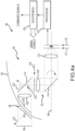
- an embodiment of an optical system 80 comprises an optical window 82 having interior and exterior surfaces with a curvature with respect to and symmetric about a central axis 88.
- Focusing optics 90 are mounted on a two-axis (roll/nod) gimbal 92 that rotates the optics' entrance pupil 94 to look through different off-axis segments 96 of the optical window to sweep a FOV 98 over a larger field-of-regard.
- the optics and entrance pupil are offset from the central axis 88 and rotated through allowed angles in roll and nod such that the FOV 98 does not cross central axis 88 behind the optical window.
- two-axis gimbal 92 comprises a roll gimbal 100 that is driven to rotate about a roll axis coincident with central axis 88 and a nod gimbal 102 mounted on the roll gimbal and driven to rotate about a nod axis 104 that is perpendicular or skew to central axis 88.
- Each gimbal includes the rotating gimbal and a drive motor to affect rotation.
- Focusing optics 90 includes optical focusing or corrector elements 105, 106, 108 and 110 and turning mirrors 112 and 114 mounted on-gimbal to collect incident radiation within the entrance pupil, correct, focus and route the incident radiation along an optical path to a focal plane.
- a polarizer is positioned in optical path between the off-axis segment 96 of optical window and a detector 116 (e.g., quad-cell or FPA) positioned at or near the focal plane.
- a polarizer 117 may be positioned off-gimbal. If polarizer 117 is a sheet polarizer it can be positioned at any arbitrary position along the optical path. If polarizer 117 is a microgrid polarizer it must be positioned at the FPA or an intermediate image of the focal plane.
- the polarizer is only aligned to the plane of incidence (as defined by surface normal 119 to the optical window) at a specified roll/nod orientation (e.g., 0°, 0°) and an orientation 180° out of phase (e.g., 180°, 180°).
- a specified roll/nod orientation e.g., 0°, 0°
- an orientation 180° out of phase e.g., 180°, 180°.
- the "mechanism" for aligning the polarizer is thus implemented by the nod gimbal and rotation of the nod gimbal.
- the sheet polarizer is implemented with a dynamic microgrid array, that array may be reconfigurable to rotate with the gimbal to maintain alignment to the plane of incidence.
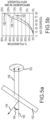
- a polarizer 118 is positioned on the nod gimbal 102 ("on-gimbal"). If polarizer 118 is a sheet polarizer it can be positioned anywhere in the optical path on the nod gimbal and optically aligned to the plane of incidence, and remains in the plane of incidence as the roll and nod gimbals rotate about their respective axes. As shown in Figure 4b , the lines of the sheet polarizer indicate the direction of the pass axis.
- polarizer 118 is a microgrid polarizer it must be positioned at an intermediate image 120 of the focal plane on the nod gimbal and optically aligned to the plane of incidence, and remains in the plane of incidence as the roll and nod gimbals rotate about their respective axis.
- a processor(s) 122 processes the signal to generate data produces.
- the processor For a sheet polarizer, the processor generates a radiance image.
- the processor may generate a radiance image, an AoLP image and a DoLP image.
- Electronics 124 use the data products to track the target and provide command signals to guide the hypersonic weapon towards the target.
- Electronics 124 may be configured to use only the AoLP image. If polarizer 117 is mounted off-gimbal, electronics 124 generate gimbal signals for the drive motors to rotate the gimbals to align the plane of incidence to the polarizer to read out the detector.
- a sheet polarizer 150 is positioned in the optical path behind an off-axis segment 152 of the optical window and aligned to the plane of incidence as defined by a surface normal 154 to the off-axis segment.
- Light 156 from a target is p-polarized by passing through both the inner and outer surfaces of off-axis segment 152.
- Light 158 that is self-emitted by off-axis segment 152 is p-polarized by pass through only the inner surface.
- the percentage of p-polarization 160 of target light 156 is thus greater than the percentage of p-polarization 162 of window light 158.
- the degree of p-polarization, and thus the difference in p-polarization increases as the angle of incidence 164 gets larger. The difference is suitably at leat 5%.
- sheet polarizer 150 Since sheet polarizer 150 is aligned to the plane of incidence it prefers p-polarized light. As a result, a greater portion of target light 156 is passed through the polarizer than window light 158 , thus increasing the contrast of target light to window light and SNR 166 at the detector. As shown, the SNR 166 at the detector also increases with increasing AOI.
- left and right sided images 170 and 172 are of untiltered radiation (no polarizer) and p-polarization filtered radiation (sheet) polarizer. Without the polarizer the background appears grey whereas with the polarizer the background appears black, which accounts for the improvement in SNR for the target in the scene.
- the improvement in SNR may allow the electronics to track the target notwithstanding the extreme aero-thermal heating of the optical window.
- a microgrid polarizer 200 is mounted on or off-gimbal in the optical path at a FPA 202 or an intermediate image of the focal plane.
- the gimbal rotates an entrance pupil 204 of the optics to look through different off-axis segments 206 and 208 of optical window 210 at a target 212.
- Segment 206 at the tip of the optical window is heated to a higher temperature than segment 208.
- the difference in temperature produces a gradient 214 in the radiance image 216 of the target.
- Microgrid polarizer 200 comprises an array of polarized pixelated filter sub-arrays 218.
- Each sub-array 218 comprises three or more filter pixels Q of which at least two filter pixels impart a linear polarization of a certain and different angular value.
- each sub-array is a 2x2 grouping of filter pixels that impart linear polarizations of 0°, 45°, 90° and 135°, respectively, with one linear polarization aligned to the P-polarization in the plane of incidence.
- the FPA pixels are grouped into 2x2 super pixels 220 corresponding to each sub-array.
- each pixel output within a super pixel includes a Px contribution at angle x for target radiation and a constant contribution W for window radiation.
- the DoLP image includes the window radiance component.
- the AoLP image may be the only useful data product.
- Each of the data products can, to some extent, be improved by aligning one or more of the polarization pixels to the plane of incidence to improve the contrast of target radiance to window radiance.
- a sub-array 250 of a microgrid polarizer includes a 2 ⁇ 2 grouping of filter pixels Q of which at least two filter pixels impart a linear polarization of a certain and different angular value, and a third pixel either is unpolarized or imparts a linear polarization of a different angular value.
- the fourth pixels is not required to create the AoLP and DoLP data products but can be used to either increase the polarization diversity, thus improving the AoLP and DoLP data products or to increase SNR. As shown, two of the pixels impart a linear polarization of 0° and the other two pixels impart linear polarizations of X° and Y°.
- the microgrid polarizer is aligned such that the 0° linear polarization lies in the plane of incidence to pass p-polarized light.
- the assignment of 0° for alignment to the plane of incidence is arbitrary, any value of linear polarization could be so aligned.
- the values of X and Y are selected to provide diversity of polarization.
- the sub-array may be larger than 2x2, in which case more than 2 pixels may have the same angular value that is aligned to the plane of incidence. The tradeoff is between SNR and polarization diversity.
- the polarizer may be implemented as a dynamic microgrid array 300 in which the individual pixels can be selectively configured to impart a linear polarization with different angular values or to be unpolarized.
- the array could be configured as a sheet polarizer 302 by setting all of the angular values to the same value.
- the array could be configured as a sub-array 304 of a microgrid polarizer by setting the angular values to different values.
- the array could be configured as a transmissive element 306 by setting all the pixels to be unpolarized "U".
- the dynamic microgrid array could be reconfigured between a sheet polarizer, a microgrid polarizer and the transmissive element as a function of mission conditions. For example, if the unfiltered radiance provides sufficient SNR to track the target, the dynamic microgrid array may be configured as a transmissive element. If the SNR falls below the minimum threshold, the dynamic microgrid array may be reconfigured as the sheet polarizer or the microgrid polarizer.
- a fixed transmissive element 400 , a fixed sheet polarizer 402 and a fixed microgrid polarizer 404 are mounted on a carrier 406 in a fixed optical system or on or off-gimbal in a gimbaled optical system.
- a shutter mechanism 408 selectively actuates carrier 406 to move one of the transmissive element 400 , sheet polarizer 402 and microgrid polarizer 404 into an optical path 410 to an FPA 412.
Landscapes
- Engineering & Computer Science (AREA)
- General Engineering & Computer Science (AREA)
- Combustion & Propulsion (AREA)
- Chemical & Material Sciences (AREA)
- Physics & Mathematics (AREA)
- Aviation & Aerospace Engineering (AREA)
- Electromagnetism (AREA)
- General Physics & Mathematics (AREA)
- Fluid Mechanics (AREA)
- Spectroscopy & Molecular Physics (AREA)
- Mechanical Engineering (AREA)
- Radar, Positioning & Navigation (AREA)
- Remote Sensing (AREA)
- Polarising Elements (AREA)
- Photometry And Measurement Of Optical Pulse Characteristics (AREA)
Claims (15)
- Optisches System zur Verwendung mit einem Fluggerät, das einer aerothermischen Heizung ausgesetzt ist, wobei das optische System Folgendes umfasst:ein optisches Fenster (12, 36, 52), das eine Innen- (34) und eine Außenfläche (32) mit einer Krümmung in Bezug auf eine Mittelachse aufweist, wobei das optische Fenster derart konfiguriert ist, dass einfallende Strahlung von einem Ziel sowohl die Innen- als auch die Außenfläche durchdringt, von welchen jede innerhalb einer Einfallsebene (38) eine P-Polarisation zu der einfallenden Zielstrahlung induziert, wobei das optische Fenster dazu konfiguriert ist, nur durch die Innenfläche durchdringende Strahlung selbst zu emittieren, welche innerhalb der Einfallsebene eine P-Polarisation zu der selbstemittierten Strahlung induziert, wobei die selbstemittierte Strahlung das Spektrum der Zielstrahlung überlappt;eine Fokussieroptik (60), die eine von der Mittelachse versetzte Eintrittspupille (62) aufweist, um durch ein achsfernes Segment (64, 152, 206, 208) des optischen Fensters (52) zu schauen, wobei die Fokussieroptik dazu konfiguriert ist, einfallende Strahlung entlang eines optischen Weges zu führen und die einfallende Strahlung in einer Fokusebene zu fokussieren;einen Detektor (72, 116) an oder nahe der Fokusebene, der dazu konfiguriert ist, einfallende Strahlung zu erfassen;einen Polarisator (74, 117, 118, 150, 200, 402, 404), der in dem optischen Weg zwischen dem optischen Fenster und dem Detektor angeordnet ist, wobei der Polarisator mindestens ein Filterpixel umfasst, das eine lineare Polarisation eines bestimmten Winkelwertes zum Filtern der einfallenden Strahlung als eine Funktion der Polarisation der einfallenden Strahlung verleiht; undeinen Mechanismus, der dazu konfiguriert ist, das mindestens eine Filterpixel an die P-Polarisation innerhalb der Einfallsebene auszurichten, wobei der Mechanismus Folgendes umfasst:einen äußeren Kardanring (100), der dazu konfiguriert ist, sich um eine erste Drehachse zu drehen; undeinen inneren Kardanring (102), der an dem äußeren Kardanring montiert ist, wobei der innere Kardanring dazu konfiguriert ist, die Eintrittspupille um eine zweite Drehachse senkrecht oder schräg zu der ersten Drehachse zu drehen.
- Optisches System nach Anspruch 1, ferner umfassend:ein Flugwerk (15); undein Antriebssystem (17), das dazu konfiguriert ist, das Flugwerk in Richtung eines Ziels mit Geschwindigkeiten größer als Mach 5 anzutreiben.
- Optisches System nach Anspruch 1, wobei der Polarisator außerhalb des Kardanrings positioniert ist und wobei der Mechanismus dazu konfiguriert ist, durch Drehen des inneren Kardanrings (102) implementiert zu werden.
- Optisches System nach Anspruch 1, wobei der Polarisator einen Blattpolarisator umfasst, der nur ein einziges Filterpixel aufweist.
- Optisches System nach Anspruch 4, wobei der Mechanismus, der den Blattpolarisator (118) auf dem inneren Kardanring in Ausrichtung auf die P-Polarisation in der Einfallsebene montiert und ausgerichtet bleibt, wenn sich der äußere und der innere Kardanring um die erste bzw. die zweite Drehachse drehen.
- Optisches System nach Anspruch 1, wobei der Detektor ein pixeliertes Fokusebenen-Array, FPA, umfasst, wobei der Polarisator ein Mikrogitterpolarisator-Array umfasst, das eine Vielzahl von polarisierten pixelierten Filter-Subarrays (218, 300) aufweist, die an dem FPA oder einem Zwischenbild der Fokusebene positioniert sind, wobei jedes Subarray drei oder mehr Filterpixel umfasst, von welchen mindestens zwei Filterpixel eine lineare Polarisation eines bestimmten und unterschiedlichen Winkelwertes verleihen, wobei der Mechanismus dazu konfiguriert ist, das Mikrogitterpolarisator-Array derart auszurichten, dass mindestens eines der Filterpixel, das eine lineare Polarisation verleiht, auf die P-Polarisation in der Einfallsebene ausgerichtet ist,
ferner umfassend einen Prozessor (77, 122), der dazu konfiguriert ist, mehrere Gruppierungen von drei oder mehr FPA-Pixeln auszulesen und zu verarbeiten, um ein Bild des Winkels der linearen Polarisation, AoLP-Bild, zu berechnen. - Optisches System nach Anspruch 6, wobei jedes Subarray mindestens zwei Filterpixel umfasst, die auf die P-Polarisation in der Einfallsebene ausgerichtet sind, oder wobei jedes Subarray ein 2×2-Array von Filterpixeln ist, die lineare Polarisationen von 0, 45, 90 bzw. 135 Grad verleihen, wobei eine der linearen Polarisationen auf die P-Polarisation in der Einfallsebene ausgerichtet ist.
- Optisches System nach Anspruch 6, wobei eine Datenreduktionsmatrix für den Mikrogitterpolarisator kalibriert ist, um P-Polarisationsbias in dem AoLP-Bild zu reduzieren.
- Optisches System nach Anspruch 6, wobei der Mikrogitterpolarisator außerhalb des Kardanrings an dem FPA positioniert ist, wobei der Mechanismus die Ausrichtung des Mikrogitterpolarisator-Arrays derart fixiert, dass mindestens eines der eine lineare Polarisation verleihenden Filterpixel in der Einfallsebene auf die P-Polarisation ausgerichtet ist.
- Optisches System nach Anspruch 6, ferner umfassend:
den Mechanismus, der den Mikrogitterpolarisator auf dem inneren Kardanring in einem Zwischenbild der Fokusebene montiert, wobei der Mikrogitterpolarisator derart montiert ist, dass das mindestens eine Filterpixel in der Einfallsebene auf die P-Polarisation ausgerichtet ist und ausgerichtet bleibt, wenn sich der äußere und der innere Kardanring um die erste bzw. die zweite Drehachse drehen, oder wobei der Mechanismus, der den Mikrogitterpolarisator außerhalb des Kardanrings derart an dem FPA montiert, dass das mindestens eine Filterpixel in der Einfallsebene auf die P-Polarisation in bekannten Winkelpositionen des inneren und des äußeren Kardanrings ausgerichtet ist, wobei der Mechanismus dazu konfiguriert ist, den äußeren und den inneren Kardanring an den bekannten Winkelpositionen zu drehen, um die erfasste einfallende Strahlung aus dem FPA auszulesen. - Optisches System nach Anspruch 1, wobei der Polarisator ein dynamisches Mikrogitter-Array umfasst, das eine Vielzahl von schaltbaren polarisierten Filterpixeln aufweist.
- Optisches System nach Anspruch 11, wobei das dynamische Mikrogitter-Array konfigurierbar ist, um alle der polarisierten Filterpixel auf den gleichen bestimmten Winkelwert umzuschalten, um P-polarisierte Strahlung durchdringen zu lassen und um die polarisierten Filterpixel umzuschalten, um eine Vielzahl von polarisierten pixelierten Filter-Subarrays auszubilden, wobei jedes Subarray drei oder mehr Filterpixel umfasst, von welchen mindestens zwei Filterpixel eine lineare Polarisation eines bestimmten und unterschiedlichen Winkelwerts verleihen, von welchen mindestens ein Filterpixel ausgerichtet ist, um P-polarisierte Strahlung zu durchdringen.
- Optisches System nach Anspruch 11, wobei das dynamische Mikrogitter-Array konfigurierbar ist, um alle der polarisierten Filterpixel in einen unpolarisierten Zustand umzuschalten.
- Optisches System nach Anspruch 1, wobei der Polarisator einen Blattpolarisator, der ausgerichtet ist, um P-polarisierte Strahlung durchdringen zu lassen, und ein Mikrogitterpolarisator-Array umfasst, das eine Vielzahl von polarisierten pixelierten Filter-Subarrays aufweist, wobei jedes Subarray drei oder mehr Filterpixel umfasst, von welchen mindestens zwei Filterpixel eine lineare Polarisation mit einem bestimmten und verschiedenen Winkelwert verleihen, ferner umfassend:einen Verschlussmechanismus, der dazu konfiguriert ist, entweder den Blattpolarisator oder das Mikrogitterpolarisator-Array selektiv in einen optischen Weg zu bewegen, der zu dem FPA führt; undeinen Prozessor, der dazu konfiguriert ist, FPA-Pixel auszulesen und zu verarbeiten, um ein Intensitätsbild zu berechnen, wenn sich der Blattpolarisator in dem optischen Weg befindet, und um ein Bild des Winkels der linearen Polarisation, AoLP-Bild, zu berechnen, wenn sich das Mikrogitterpolarisator-Array in dem optischen Weg befindet.
- Optisches System nach Anspruch 14, wobei der Verschlussmechanismus dazu konfiguriert ist, sowohl den Blattpolarisator als auch das Mikrogitterpolarisator-Array selektiv aus dem optischen Weg zu entfernen.
Applications Claiming Priority (2)
| Application Number | Priority Date | Filing Date | Title |
|---|---|---|---|
| US14/921,774 US9927289B2 (en) | 2015-10-23 | 2015-10-23 | Polarization filtering for window self-emission due to aero-thermal heating |
| PCT/US2016/046158 WO2017078815A1 (en) | 2015-10-23 | 2016-08-09 | Polarization filtering for window self emission due to aero-thermal heating |
Publications (2)
| Publication Number | Publication Date |
|---|---|
| EP3334997A1 EP3334997A1 (de) | 2018-06-20 |
| EP3334997B1 true EP3334997B1 (de) | 2024-09-25 |
Family
ID=58163177
Family Applications (1)
| Application Number | Title | Priority Date | Filing Date |
|---|---|---|---|
| EP16840301.2A Active EP3334997B1 (de) | 2015-10-23 | 2016-08-09 | Polarisationsfilterung für selbstemission von fenstern durch aerothermische heizung |
Country Status (4)
| Country | Link |
|---|---|
| US (1) | US9927289B2 (de) |
| EP (1) | EP3334997B1 (de) |
| ES (1) | ES2992789T3 (de) |
| WO (1) | WO2017078815A1 (de) |
Families Citing this family (3)
| Publication number | Priority date | Publication date | Assignee | Title |
|---|---|---|---|---|
| CN105654430B (zh) * | 2015-12-24 | 2017-04-19 | 华中科技大学 | 一种反差约束的气动热辐射校正方法 |
| US10437132B1 (en) | 2018-03-20 | 2019-10-08 | Raytheon Company | Methods and apparatus for acousto-optic non-uniformity correction and counter-countermeasure mechanisms |
| US10710752B2 (en) * | 2018-10-16 | 2020-07-14 | The Boeing Company | System and method for inspecting aircraft windows |
Family Cites Families (8)
| Publication number | Priority date | Publication date | Assignee | Title |
|---|---|---|---|---|
| US5135183A (en) | 1991-09-23 | 1992-08-04 | Hughes Aircraft Company | Dual-image optoelectronic imaging apparatus including birefringent prism arrangement |
| US20070045545A1 (en) * | 2005-08-26 | 2007-03-01 | Light David O | Hyperspectral sensor using tunable filter |
| US8466964B2 (en) | 2007-04-02 | 2013-06-18 | Opto-Knowledge Systems, Inc. | Multispectral uncooled thermal infrared camera system |
| US7858939B2 (en) | 2008-11-21 | 2010-12-28 | Lockheed Martin Corporation | FPA combining SAL and imaging |
| US8575527B2 (en) | 2010-11-10 | 2013-11-05 | Lockheed Martin Corporation | Vehicle having side portholes and an array of fixed EO imaging sub-systems utilizing the portholes |
| US8842216B2 (en) | 2012-08-30 | 2014-09-23 | Raytheon Company | Movable pixelated filter array |
| GB2515123B (en) * | 2013-06-14 | 2018-06-06 | Mbda Uk Ltd | Improvements in and relating to missile seekers |
| US9347743B2 (en) | 2013-07-17 | 2016-05-24 | Raytheon Company | Offset aperture dual-gimbaled optical system |
-
2015
- 2015-10-23 US US14/921,774 patent/US9927289B2/en active Active
-
2016
- 2016-08-09 ES ES16840301T patent/ES2992789T3/es active Active
- 2016-08-09 EP EP16840301.2A patent/EP3334997B1/de active Active
- 2016-08-09 WO PCT/US2016/046158 patent/WO2017078815A1/en not_active Ceased
Also Published As
| Publication number | Publication date |
|---|---|
| EP3334997A1 (de) | 2018-06-20 |
| WO2017078815A1 (en) | 2017-05-11 |
| US9927289B2 (en) | 2018-03-27 |
| ES2992789T3 (en) | 2024-12-18 |
| US20170115160A1 (en) | 2017-04-27 |
Similar Documents
| Publication | Publication Date | Title |
|---|---|---|
| US6359681B1 (en) | Combined laser/FLIR optics system | |
| US7763857B2 (en) | Infrared imaging optical system with varying focal length across the field of view | |
| US8326142B2 (en) | Optical image systems | |
| US10057509B2 (en) | Multiple-sensor imaging system | |
| US10739454B2 (en) | Low cost, high accuracy laser warning receiver | |
| US9225914B2 (en) | Infrared imaging system | |
| JP2009527953A (ja) | 光多重化撮像システムおよび操作方法 | |
| WO2014189558A2 (en) | Optical configuration for a compact integrated day/night viewing and laser range finding system | |
| WO2015012902A1 (en) | Four-axis gimbaled airborne sensor | |
| US9927289B2 (en) | Polarization filtering for window self-emission due to aero-thermal heating | |
| US20100108800A1 (en) | Object detection system having an image detection system | |
| JP3910643B2 (ja) | 一体型レーザ/赤外線前方監視光学装置 | |
| FR2523293A1 (fr) | Systeme de conduite de tir a double ecartometrie | |
| Masterson et al. | MWIR wide-area step and stare imager |
Legal Events
| Date | Code | Title | Description |
|---|---|---|---|
| STAA | Information on the status of an ep patent application or granted ep patent |
Free format text: STATUS: UNKNOWN |
|
| STAA | Information on the status of an ep patent application or granted ep patent |
Free format text: STATUS: THE INTERNATIONAL PUBLICATION HAS BEEN MADE |
|
| PUAI | Public reference made under article 153(3) epc to a published international application that has entered the european phase |
Free format text: ORIGINAL CODE: 0009012 |
|
| STAA | Information on the status of an ep patent application or granted ep patent |
Free format text: STATUS: REQUEST FOR EXAMINATION WAS MADE |
|
| 17P | Request for examination filed |
Effective date: 20180314 |
|
| AK | Designated contracting states |
Kind code of ref document: A1 Designated state(s): AL AT BE BG CH CY CZ DE DK EE ES FI FR GB GR HR HU IE IS IT LI LT LU LV MC MK MT NL NO PL PT RO RS SE SI SK SM TR |
|
| AX | Request for extension of the european patent |
Extension state: BA ME |
|
| DAV | Request for validation of the european patent (deleted) | ||
| DAX | Request for extension of the european patent (deleted) | ||
| STAA | Information on the status of an ep patent application or granted ep patent |
Free format text: STATUS: EXAMINATION IS IN PROGRESS |
|
| 17Q | First examination report despatched |
Effective date: 20201001 |
|
| GRAP | Despatch of communication of intention to grant a patent |
Free format text: ORIGINAL CODE: EPIDOSNIGR1 |
|
| STAA | Information on the status of an ep patent application or granted ep patent |
Free format text: STATUS: GRANT OF PATENT IS INTENDED |
|
| RIC1 | Information provided on ipc code assigned before grant |
Ipc: F42B 15/08 20060101ALI20240315BHEP Ipc: F42B 15/34 20060101ALI20240315BHEP Ipc: F42B 10/46 20060101ALI20240315BHEP Ipc: F41G 7/22 20060101AFI20240315BHEP |
|
| INTG | Intention to grant announced |
Effective date: 20240415 |
|
| GRAS | Grant fee paid |
Free format text: ORIGINAL CODE: EPIDOSNIGR3 |
|
| GRAA | (expected) grant |
Free format text: ORIGINAL CODE: 0009210 |
|
| STAA | Information on the status of an ep patent application or granted ep patent |
Free format text: STATUS: THE PATENT HAS BEEN GRANTED |
|
| AK | Designated contracting states |
Kind code of ref document: B1 Designated state(s): AL AT BE BG CH CY CZ DE DK EE ES FI FR GB GR HR HU IE IS IT LI LT LU LV MC MK MT NL NO PL PT RO RS SE SI SK SM TR |
|
| REG | Reference to a national code |
Ref country code: GB Ref legal event code: FG4D |
|
| REG | Reference to a national code |
Ref country code: CH Ref legal event code: EP |
|
| REG | Reference to a national code |
Ref country code: NL Ref legal event code: FP |
|
| REG | Reference to a national code |
Ref country code: DE Ref legal event code: R096 Ref document number: 602016089588 Country of ref document: DE |
|
| REG | Reference to a national code |
Ref country code: SE Ref legal event code: TRGR |
|
| REG | Reference to a national code |
Ref country code: IE Ref legal event code: FG4D |
|
| REG | Reference to a national code |
Ref country code: ES Ref legal event code: FG2A Ref document number: 2992789 Country of ref document: ES Kind code of ref document: T3 Effective date: 20241218 |
|
| REG | Reference to a national code |
Ref country code: LT Ref legal event code: MG9D |
|
| PG25 | Lapsed in a contracting state [announced via postgrant information from national office to epo] |
Ref country code: GR Free format text: LAPSE BECAUSE OF FAILURE TO SUBMIT A TRANSLATION OF THE DESCRIPTION OR TO PAY THE FEE WITHIN THE PRESCRIBED TIME-LIMIT Effective date: 20241226 Ref country code: FI Free format text: LAPSE BECAUSE OF FAILURE TO SUBMIT A TRANSLATION OF THE DESCRIPTION OR TO PAY THE FEE WITHIN THE PRESCRIBED TIME-LIMIT Effective date: 20240925 |
|
| PG25 | Lapsed in a contracting state [announced via postgrant information from national office to epo] |
Ref country code: BG Free format text: LAPSE BECAUSE OF FAILURE TO SUBMIT A TRANSLATION OF THE DESCRIPTION OR TO PAY THE FEE WITHIN THE PRESCRIBED TIME-LIMIT Effective date: 20240925 |
|
| PG25 | Lapsed in a contracting state [announced via postgrant information from national office to epo] |
Ref country code: LV Free format text: LAPSE BECAUSE OF FAILURE TO SUBMIT A TRANSLATION OF THE DESCRIPTION OR TO PAY THE FEE WITHIN THE PRESCRIBED TIME-LIMIT Effective date: 20240925 |
|
| PG25 | Lapsed in a contracting state [announced via postgrant information from national office to epo] |
Ref country code: RS Free format text: LAPSE BECAUSE OF FAILURE TO SUBMIT A TRANSLATION OF THE DESCRIPTION OR TO PAY THE FEE WITHIN THE PRESCRIBED TIME-LIMIT Effective date: 20241225 |
|
| PG25 | Lapsed in a contracting state [announced via postgrant information from national office to epo] |
Ref country code: RS Free format text: LAPSE BECAUSE OF FAILURE TO SUBMIT A TRANSLATION OF THE DESCRIPTION OR TO PAY THE FEE WITHIN THE PRESCRIBED TIME-LIMIT Effective date: 20241225 Ref country code: LV Free format text: LAPSE BECAUSE OF FAILURE TO SUBMIT A TRANSLATION OF THE DESCRIPTION OR TO PAY THE FEE WITHIN THE PRESCRIBED TIME-LIMIT Effective date: 20240925 Ref country code: GR Free format text: LAPSE BECAUSE OF FAILURE TO SUBMIT A TRANSLATION OF THE DESCRIPTION OR TO PAY THE FEE WITHIN THE PRESCRIBED TIME-LIMIT Effective date: 20241226 Ref country code: FI Free format text: LAPSE BECAUSE OF FAILURE TO SUBMIT A TRANSLATION OF THE DESCRIPTION OR TO PAY THE FEE WITHIN THE PRESCRIBED TIME-LIMIT Effective date: 20240925 Ref country code: BG Free format text: LAPSE BECAUSE OF FAILURE TO SUBMIT A TRANSLATION OF THE DESCRIPTION OR TO PAY THE FEE WITHIN THE PRESCRIBED TIME-LIMIT Effective date: 20240925 |
|
| REG | Reference to a national code |
Ref country code: AT Ref legal event code: MK05 Ref document number: 1726941 Country of ref document: AT Kind code of ref document: T Effective date: 20240925 |
|
| PG25 | Lapsed in a contracting state [announced via postgrant information from national office to epo] |
Ref country code: IS Free format text: LAPSE BECAUSE OF FAILURE TO SUBMIT A TRANSLATION OF THE DESCRIPTION OR TO PAY THE FEE WITHIN THE PRESCRIBED TIME-LIMIT Effective date: 20250125 Ref country code: PT Free format text: LAPSE BECAUSE OF FAILURE TO SUBMIT A TRANSLATION OF THE DESCRIPTION OR TO PAY THE FEE WITHIN THE PRESCRIBED TIME-LIMIT Effective date: 20250127 |
|
| PG25 | Lapsed in a contracting state [announced via postgrant information from national office to epo] |
Ref country code: SM Free format text: LAPSE BECAUSE OF FAILURE TO SUBMIT A TRANSLATION OF THE DESCRIPTION OR TO PAY THE FEE WITHIN THE PRESCRIBED TIME-LIMIT Effective date: 20240925 Ref country code: RO Free format text: LAPSE BECAUSE OF FAILURE TO SUBMIT A TRANSLATION OF THE DESCRIPTION OR TO PAY THE FEE WITHIN THE PRESCRIBED TIME-LIMIT Effective date: 20240925 |
|
| PG25 | Lapsed in a contracting state [announced via postgrant information from national office to epo] |
Ref country code: EE Free format text: LAPSE BECAUSE OF FAILURE TO SUBMIT A TRANSLATION OF THE DESCRIPTION OR TO PAY THE FEE WITHIN THE PRESCRIBED TIME-LIMIT Effective date: 20240925 Ref country code: AT Free format text: LAPSE BECAUSE OF FAILURE TO SUBMIT A TRANSLATION OF THE DESCRIPTION OR TO PAY THE FEE WITHIN THE PRESCRIBED TIME-LIMIT Effective date: 20240925 |
|
| PG25 | Lapsed in a contracting state [announced via postgrant information from national office to epo] |
Ref country code: CZ Free format text: LAPSE BECAUSE OF FAILURE TO SUBMIT A TRANSLATION OF THE DESCRIPTION OR TO PAY THE FEE WITHIN THE PRESCRIBED TIME-LIMIT Effective date: 20240925 Ref country code: PL Free format text: LAPSE BECAUSE OF FAILURE TO SUBMIT A TRANSLATION OF THE DESCRIPTION OR TO PAY THE FEE WITHIN THE PRESCRIBED TIME-LIMIT Effective date: 20240925 |
|
| PG25 | Lapsed in a contracting state [announced via postgrant information from national office to epo] |
Ref country code: SK Free format text: LAPSE BECAUSE OF FAILURE TO SUBMIT A TRANSLATION OF THE DESCRIPTION OR TO PAY THE FEE WITHIN THE PRESCRIBED TIME-LIMIT Effective date: 20240925 |
|
| REG | Reference to a national code |
Ref country code: DE Ref legal event code: R097 Ref document number: 602016089588 Country of ref document: DE |
|
| PG25 | Lapsed in a contracting state [announced via postgrant information from national office to epo] |
Ref country code: DK Free format text: LAPSE BECAUSE OF FAILURE TO SUBMIT A TRANSLATION OF THE DESCRIPTION OR TO PAY THE FEE WITHIN THE PRESCRIBED TIME-LIMIT Effective date: 20240925 |
|
| PLBE | No opposition filed within time limit |
Free format text: ORIGINAL CODE: 0009261 |
|
| STAA | Information on the status of an ep patent application or granted ep patent |
Free format text: STATUS: NO OPPOSITION FILED WITHIN TIME LIMIT |
|
| PGFP | Annual fee paid to national office [announced via postgrant information from national office to epo] |
Ref country code: NL Payment date: 20250723 Year of fee payment: 10 |
|
| 26N | No opposition filed |
Effective date: 20250626 |
|
| PGFP | Annual fee paid to national office [announced via postgrant information from national office to epo] |
Ref country code: ES Payment date: 20250901 Year of fee payment: 10 |
|
| PGFP | Annual fee paid to national office [announced via postgrant information from national office to epo] |
Ref country code: DE Payment date: 20250724 Year of fee payment: 10 |
|
| PGFP | Annual fee paid to national office [announced via postgrant information from national office to epo] |
Ref country code: NO Payment date: 20250725 Year of fee payment: 10 |
|
| PGFP | Annual fee paid to national office [announced via postgrant information from national office to epo] |
Ref country code: IT Payment date: 20250723 Year of fee payment: 10 |
|
| PGFP | Annual fee paid to national office [announced via postgrant information from national office to epo] |
Ref country code: GB Payment date: 20250725 Year of fee payment: 10 |
|
| PGFP | Annual fee paid to national office [announced via postgrant information from national office to epo] |
Ref country code: FR Payment date: 20250725 Year of fee payment: 10 |
|
| PGFP | Annual fee paid to national office [announced via postgrant information from national office to epo] |
Ref country code: SE Payment date: 20250723 Year of fee payment: 10 |
|
| PG25 | Lapsed in a contracting state [announced via postgrant information from national office to epo] |
Ref country code: HR Free format text: LAPSE BECAUSE OF FAILURE TO SUBMIT A TRANSLATION OF THE DESCRIPTION OR TO PAY THE FEE WITHIN THE PRESCRIBED TIME-LIMIT Effective date: 20240925 |
|
| REG | Reference to a national code |
Ref country code: CH Ref legal event code: H13 Free format text: ST27 STATUS EVENT CODE: U-0-0-H10-H13 (AS PROVIDED BY THE NATIONAL OFFICE) Effective date: 20260324 |
|
| PG25 | Lapsed in a contracting state [announced via postgrant information from national office to epo] |
Ref country code: MC Free format text: LAPSE BECAUSE OF FAILURE TO SUBMIT A TRANSLATION OF THE DESCRIPTION OR TO PAY THE FEE WITHIN THE PRESCRIBED TIME-LIMIT Effective date: 20240925 |
|
| PG25 | Lapsed in a contracting state [announced via postgrant information from national office to epo] |
Ref country code: LU Free format text: LAPSE BECAUSE OF NON-PAYMENT OF DUE FEES Effective date: 20250809 |
|
| PG25 | Lapsed in a contracting state [announced via postgrant information from national office to epo] |
Ref country code: CH Free format text: LAPSE BECAUSE OF NON-PAYMENT OF DUE FEES Effective date: 20250831 |