EP3335268B1 - Oberflächenwellenantennensystem - Google Patents
Oberflächenwellenantennensystem Download PDFInfo
- Publication number
- EP3335268B1 EP3335268B1 EP16753413.0A EP16753413A EP3335268B1 EP 3335268 B1 EP3335268 B1 EP 3335268B1 EP 16753413 A EP16753413 A EP 16753413A EP 3335268 B1 EP3335268 B1 EP 3335268B1
- Authority
- EP
- European Patent Office
- Prior art keywords
- antenna
- antenna system
- cover
- wired
- radiation
- Prior art date
- Legal status (The legal status is an assumption and is not a legal conclusion. Google has not performed a legal analysis and makes no representation as to the accuracy of the status listed.)
- Active
Links
Images



Classifications
-
- H—ELECTRICITY
- H01—ELECTRIC ELEMENTS
- H01Q—ANTENNAS, i.e. RADIO AERIALS
- H01Q9/00—Electrically-short antennas having dimensions not more than twice the operating wavelength and consisting of conductive active radiating elements
- H01Q9/04—Resonant antennas
- H01Q9/30—Resonant antennas with feed to end of elongated active element, e.g. unipole
- H01Q9/32—Vertical arrangement of element
- H01Q9/36—Vertical arrangement of element with top loading
-
- H—ELECTRICITY
- H01—ELECTRIC ELEMENTS
- H01Q—ANTENNAS, i.e. RADIO AERIALS
- H01Q1/00—Details of, or arrangements associated with, antennas
- H01Q1/04—Adaptation for subterranean or subaqueous use
-
- H—ELECTRICITY
- H01—ELECTRIC ELEMENTS
- H01Q—ANTENNAS, i.e. RADIO AERIALS
- H01Q1/00—Details of, or arrangements associated with, antennas
- H01Q1/44—Details of, or arrangements associated with, antennas using equipment having another main function to serve additionally as an antenna, e.g. means for giving an antenna an aesthetic aspect
- H01Q1/46—Electric supply lines or communication lines
-
- H—ELECTRICITY
- H01—ELECTRIC ELEMENTS
- H01Q—ANTENNAS, i.e. RADIO AERIALS
- H01Q5/00—Arrangements for simultaneous operation of antennas on two or more different wavebands, e.g. dual-band or multi-band arrangements
- H01Q5/10—Resonant antennas
- H01Q5/15—Resonant antennas for operation of centre-fed antennas comprising one or more collinear, substantially straight or elongated active elements
-
- H—ELECTRICITY
- H01—ELECTRIC ELEMENTS
- H01Q—ANTENNAS, i.e. RADIO AERIALS
- H01Q5/00—Arrangements for simultaneous operation of antennas on two or more different wavebands, e.g. dual-band or multi-band arrangements
- H01Q5/30—Arrangements for providing operation on different wavebands
- H01Q5/307—Individual or coupled radiating elements, each element being fed in an unspecified way
- H01Q5/342—Individual or coupled radiating elements, each element being fed in an unspecified way for different propagation modes
- H01Q5/357—Individual or coupled radiating elements, each element being fed in an unspecified way for different propagation modes using a single feed point
- H01Q5/364—Creating multiple current paths
- H01Q5/371—Branching current paths
-
- H—ELECTRICITY
- H01—ELECTRIC ELEMENTS
- H01Q—ANTENNAS, i.e. RADIO AERIALS
- H01Q9/00—Electrically-short antennas having dimensions not more than twice the operating wavelength and consisting of conductive active radiating elements
- H01Q9/04—Resonant antennas
- H01Q9/44—Resonant antennas with a plurality of divergent straight elements, e.g. V-dipole, X-antenna; with a plurality of elements having mutually inclined substantially straight portions
- H01Q9/46—Resonant antennas with a plurality of divergent straight elements, e.g. V-dipole, X-antenna; with a plurality of elements having mutually inclined substantially straight portions with rigid elements diverging from single point
Definitions
- the invention relates to an antenna system.
- the invention relates to an antenna system with vertical and/or elliptical polarization suitable for transmitting and/or receiving surface waves in a wide frequency band including in particular all or part of the low, medium and high frequencies between 30 kHz and about 30 MHz, i.e. LF, MF and HF.
- Antennas using only a surface wave as a propagation vector are very few in number.
- Current surface wave systems use whip or biconical type antennas which are poorly suited for radar applications.
- space wave field also called ionospheric radiation
- the invention aims to overcome at least some of the drawbacks of known antennas.
- the invention aims to provide, in at least one embodiment of the invention, an antenna system whose preferential radiation is surface wave radiation.
- the invention also aims to provide, in at least one embodiment, an antenna system whose ionospheric radiation is reduced.
- the invention also aims to provide, in at least one embodiment of the invention, an antenna system that is simple to produce.
- the invention also aims to provide, in at least one embodiment, a discrete antenna system whose vertical bulk is small.
- the invention also aims to provide, in at least one embodiment, an antenna system whose bandwidth can be easily modified.
- electrically short antenna in the vertical plane is meant an antenna emitting radiation in a preferential wavelength called the central wavelength ⁇ 0 , and whose vertical size is less than a quarter of the central wavelength. If the antenna transmits on a frequency band, the central wavelength corresponds to the wavelength associated with the central frequency of the frequency band.
- the antenna is for example an antenna as described in the French patent application FR2965978 , a whip antenna, a PIFA type antenna (for Planar Inverted F-Shaped Antenna in English), M-shaped antenna, etc.
- An antenna system therefore allows preferential radiation in surface waves, as well as the reduction of the ionospheric radiation of an antenna thanks to the use of one or more wire covers, so as to emit only surface waves.
- the wired covers are electrically connected to the antenna, so that a power supply from the antenna also supplies the wired covers.
- the wired covers radiate at the central frequency f 0 and allow modification of the radiation pattern of the antenna so as to reduce the ionospheric radiation of the antenna system.
- the wired covers are formed from a metal wire or a small section metal tube.
- the vertical size of the antenna system is between 0.05 ⁇ 0 and 0.3 ⁇ 0 .
- the antenna system is therefore discreet. In addition, it is less sensitive to wind, blast, lightning, earthquakes, etc.
- the length of the wired cover is less than or equal to 2 ⁇ 0 .
- said at least one antenna is configured to transmit/receive directional radiation along a direction of radiation, and at least one wired cover extends along a main direction substantially parallel to the direction of radiation.
- the ionospheric radiation of the antenna system is further reduced in the radiation direction of the antenna when this is a directional antenna.
- At least one wired cover extends in a direction forming an angle of between ⁇ 10° and 10° with the surface of the conductive medium.
- the wired cover extends in a direction substantially parallel to the surface of the conductive medium. “Substantially parallel” means an angle between the direction of each cover and the surface of the conductive medium comprised between ⁇ 5° and 5°.
- the wired cover can also be strictly parallel to the surface of the conductive medium.
- the reduction of ionospheric radiation and the directivity of the antenna are improved.
- an antenna system comprises at least two wire covers extending in main directions different from each other.
- the presence of a plurality of wired covers allows an improved reduction of ionospheric radiation in several azimuths.
- the conductive medium comprises a ground plane, to which each antenna is connected.
- the ground plane makes it possible to improve the conductivity of the conductive medium if this conductivity is too low.
- At least one wired cowl comprises at least one localized element adapted to allow the resonance of said cowl at a multitude of frequencies.
- the localized elements which can be resistive, capacitive or inductive elements, make it possible to form on the cover(s) open circuits (or high impedance) or closed circuits according to the operating frequencies, forming thus current traps.
- the localized elements are thus adapted to obtain a multifrequency antenna system (that is to say with multiple resonances) via said current traps.
- the localized elements can also make it possible to reproduce the RLC resonance of the cowl with a reduced physical length of the cowl but an equivalent electrical length.
- the localized elements are thus adapted to modify the electrical length of the cover.
- At least one wired cover comprises a plurality of wired elements connected to each other so as to form a surface cover or a volume cover.
- the surface or volume covers make it possible to increase the bandwidth of the antenna system.
- surface or volume covers are suitable for use with broadband antennas.
- the wired elements are, for example, strands composed of tubes or metal wires.
- the invention also relates to an antenna system characterized in combination by all or some of the characteristics mentioned above or below.
- An orthogonal marker Oxyz is used in each figure representing antenna systems according to the different embodiments of the invention.
- FIG. 1 schematically represents in perspective an antenna system according to a first embodiment of the invention.
- the antenna system 20 comprises an antenna 22, here an M-shaped antenna comprising a horizontal radiating element 24 connected to three vertical radiating elements 26a, 26b, 26c, themselves connected to a conductive medium 28.
- the conductive medium 28 is represented by an electrical ground symbol connected to the ground.
- the conductive medium 28 is an imperfect conductive medium, for example soil (earth, sand, etc.) or water (sea, salt marsh, lake, etc.).
- the antenna is powered at the level of the vertical radiating element 26b by a generator 29.
- the antenna system 20 further comprises a wire cover 30 electrically connected to the antenna 22 at the level of the center of the cover.
- the wire cover 30 is connected to the antenna 22 at the level of the center of the vertical radiating element 24 .
- the wire cover 30 is single-stranded (that is to say it is composed of a single radiating wire), has a length greater than 0.8 ⁇ 0 and extends in a direction substantially parallel to the surface of the middle 28 conductor.
- the conductive medium 28 has an electrical conductivity which varies according to its composition.
- the sea, salt marshes or salt lakes have high electrical conductivity, and earth and sand have low electrical conductivity.
- the antenna system 20 is completed by a ground plane, connected to the antenna 22, and buried below or on the surface of the conductive medium 28.
- the ground plane can be formed of a plate, or of a set of conductive wires forming a mesh, etc.
- the ground plane can take several shapes, for example a circle, a polygon (regular or not), etc.
- the ground plane extends under the whole of the antenna system 20, that is to say that the projection of the antenna system 20 on the conductive medium 28 along the axis Oz is included in the surface occupied by the ground plane.
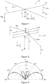
- FIG. 2 schematically represents in perspective an antenna system according to a second embodiment of the invention.
- the antenna system 20 comprises an antenna 22 as described in the French patent application FR2965978 filed by the applicant.
- the antenna system 20 comprises a wire cover 30 electrically connected to the antenna 22 at the level of the center of the cover.
- the wire cover 30 is single-stranded, and is composed of two sub-strands 32a, 32b of equal lengths, connected at one of their ends and arranged in the same plane.
- the two sub-strands are connected by forming an angle, due to the difference between the height h1 at which the sub-strands are connected and the height of the other two ends of the sub-strands.
- the angle is equal to 180° and therefore the sub-strands are aligned and the cover is parallel to the surface of the conductive medium 28, like the cover previously described in the first embodiment of achievement.
- FIG. 3 represents a radiation diagram according to the yOz plane (known as the zenithal radiation diagram) of the antenna system according to the second embodiment of the invention, in which the wired cover has a length of 0.8 ⁇ 0 , the height h1 is equal at 0.06 ⁇ 0 , the height h2 is equal to 0.05 ⁇ 0 and the length L of the antenna is equal to 0.3 ⁇ 0 .
- the radiation from the antenna system is therefore mainly surface wave radiation, and the ionospheric radiation from the antenna system is greatly reduced compared to an antenna 22 without cover.
- the gain of the antenna system (expressed in dB relative to the maximum radiation of the antenna system) is between 0 and -5 dB for radiation angles included in the intervals [-90°, -60°] and [60 °, 90°], and is less than -10dB in the interval [-50°, 50°].
- FIG. 4 schematically represents in perspective an antenna system according to a third embodiment of the invention.
- the antenna system 20 comprises an antenna 22 of the PIFA type (for Planar Inverted F-Shaped Antenna ).
- the antenna 22 is composed of two vertical radiating elements 34a, 34b connected to a horizontal radiating element 36.
- the antenna system 20 comprises a single-strand wire cover 30 electrically connected to the antenna 22 at the level of the center of the wire cover 30.
- FIG. 5 schematically represents in perspective an antenna system according to a fourth embodiment of the invention.
- the antenna system 20 comprises an antenna 22 of the shortened whip antenna type.
- the antenna 22 is a monopole antenna comprising a single radiating wire, and the antenna system 20 comprises a single-strand wire cover 30 electrically connected to one end of the antenna 22 at the level of the center of the wire cover 30.
- FIG. 6 , 7 , 8 , 10 and 11 schematically represent in perspective an antenna system 20 according to different embodiments comprising an M-shaped antenna 22 as described above with reference to the first embodiment.
- THE figure 6 And 7 represent respectively a fifth and a sixth embodiment of the invention, in which the wire cover 30 is single-stranded and is connected to the antenna according to different arrangements, in particular connected to any point of the horizontal radiating element 24 in the fifth embodiment ( figure 6 ) or at one of the ends of the horizontal radiating element 24 in the sixth embodiment ( figure 7 ).
- wired cover 30 make it possible in particular to adapt the antenna system 20 according to different configurations so as to adapt to the constraints of the environment in which the antenna system 20 is arranged, the configurations having identical operations.
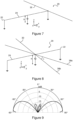
- THE figure 8 , 10 and 11 respectively represent a seventh, an eighth and a ninth embodiment of the invention, in which the wired cover 30 is a so-called multi-strand cover, comprising a plurality of wire elements, here two strands 38a, 38b connected at their center and s extending in different directions so as to form an angle ⁇ .
- the strands are of the same length greater than 0.8 ⁇ 0 .
- the cover is connected to the antenna according to different arrangements, in particular connected to the center of the horizontal radiating element 24 in the seventh embodiment ( figure 8 ), at any point of the horizontal radiating element 24 in the eighth embodiment ( figure 10 ) or at one of the ends of the horizontal radiating element 24 in the ninth embodiment ( figure 11 ).
- FIG 9 represents a radiation diagram according to the yOz plane (known as the zenithal radiation diagram) of the antenna system according to the seventh embodiment of the invention, in which each strand of the cover has a length of 1.1 ⁇ 0 , the element 24 horizontal radiating from the antenna 22 has a length of 0.7 ⁇ 0 and the antenna has a height h of 0.08 ⁇ 0 .
- the radiation from the antenna system is therefore mainly surface wave radiation, and the ionospheric radiation from the antenna system is greatly reduced compared to an antenna 22 without cover.
- the gain of the antenna system (expressed in dB relative to the maximum radiation of the antenna system) is between 0 and -5 dB for radiation angles included in the intervals [-90°, -60°] and [60 °, 90°], is less than -10dB in the interval [-50°, 50°], and less than -15dB in the interval [-40°, 40°].
- FIG 12 , 13 and 14 schematically represent in perspective an antenna system 20 respectively according to a tenth, an eleventh and a twelfth embodiment.
- Each antenna system comprises an M-shaped antenna 22 according to different particular embodiments.
- the antenna 22 comprises three horizontal radiating elements 24a, 24b, 24c of the same lengths, each connected at their ends to a vertical radiating element and all connected at their center to a single vertical radiating element 26b.
- This embodiment of the antenna allows a widening of the radiation frequency band of the antenna.
- the system 22 antenna comprises a multi-stranded wire cover 30 composed of two strands 38a, 38b, as described above, the ends of the strands being connected two by two by wire connections 40a, 40b so as to form a surface cover, that is to say say equivalent to a radiating surface.
- This surface cover therefore has a widened operating frequency band in connection with the widening of the operating band of the antenna 22.
- the antenna 22 comprises two horizontal radiating elements 24, 124 of different lengths each connected at their ends to a vertical radiating element and all connected at their center to a single vertical radiating element.
- a first horizontal radiating element 24 is of suitable length to radiate at a first central frequency f 0 (associated with the wavelength ⁇ 0 ) and a second horizontal element 124 is of suitable length to radiate at a second central frequency f bis ( associated with the wavelength ⁇ bis ).
- the antenna is said to be double resonant.
- the antenna system 22 comprises a wire cover 30 composed of several strands, here three strands 38a, 38b, 38c, arranged in parallel, of different lengths and connected at their ends.
- a first strand 38b has a length greater than 0.8 ⁇ 0 and is suitable for radiating at the first central frequency f 0
- two second and third strands 38a, 38c have a length greater than 0.8 ⁇ bis and are suitable for radiate at the central frequency f bis .
- the wire cover 30 is thus double resonant and allows the reduction of the ionospheric radiation for the central frequencies f 0 and f bis .
- the antenna 22 comprises five vertical radiating elements 26a, 26b, 26c, 26d, 26e connected to the horizontal radiating element 24.
- the antenna 22 comprises localized elements 42a, 42b, 42c, 42d arranged on two of the vertical radiating elements and on the horizontal radiating element 24, allowing the formation of current traps and/or allowing the electrical lengths to be modified. of the antenna 22.
- the localized elements can be resistive, capacitive (capacitors) or inductive (coils). These localized elements are commonly called " load " in English.
- the antenna system 22 comprises two multi-strand covers 30a, 30b connected to the horizontal radiating element of the antenna, each of the covers comprising two strands.
- the covers further comprise localized elements 42e, 42f, 42g, 42h, 42i, 42j, 42k, 421 allowing the formation of current traps and/or allowing the electrical lengths of the covers to be modified.
- the lumped elements are resistive (eg a resistor), capacitive (eg a capacitor) or inductive (eg a coil).
- At least one cover can be a volume type cover so as to further broaden the bandwidth of the antenna system
- the antenna system can comprise more than two covers, several antennas, etc.
Landscapes
- Variable-Direction Aerials And Aerial Arrays (AREA)
- Details Of Aerials (AREA)
- Aerials With Secondary Devices (AREA)
Claims (7)
- Oberflächenwellenantennensystem (20), umfassend:- mindestens eine Antenne (22) mit vertikaler oder elliptischer Polarisierung und angepasst, um eine Strahlung in mindestens einem Frequenzband zu übertragen/zu empfangen, das auf einer mittleren Frequenz f0 zentriert ist, die mit einer mittleren Wellenlänge λ0 verknüpft ist, wobei die mindestens eine Antenne (22) in der vertikalen Ebene elektrisch kurz ist, sodass die Antenne (22) eine vertikale Abmessung kleiner als 0,25 λ0 aufweist, wobei die Antenne (22) dazu ausgelegt ist, mit einem leitfähigen Medium (28) verbunden zu werden, das eine im Wesentlichen horizontale Oberfläche aufweist,wobei das Antennensystem (20) dadurch gekennzeichnet ist, dass es weiter umfasst:- mindestens eine Kabelabdeckung (30; 30a, 30b; 38a, 38b; 38a, 38b, 38c) mit einer Länge größer oder gleich 0,8 λ0, die elektrisch mit mindestens einer Antenne (22) an der Mitte der Abdeckung (30; 30a, 30b; 38a, 38b) verbunden ist und angepasst ist, um mindestens bei der zentralen Frequenz f0 der Antenne (22) zu strahlen.
- Antennensystem nach Anspruch 1, dadurch gekennzeichnet, dass sich mindestens eine Kabelabdeckung (30; 30a, 30b) in einer Richtung erstreckt, die einen Winkel zwischen -10° und 10° mit der Oberfläche des leitfähigen Mediums (28) bildet.
- Antennensystem nach Anspruch 2, dadurch gekennzeichnet, dass sich die mindestens eine Kabelabdeckung (30; 30a, 30b, 38a, 38b; 38a, 38b, 38c) in einer Richtung im Wesentlichen parallel zur Oberfläche des leitfähigen Mediums (28) erstreckt.
- Antennensystem nach einem der Ansprüche 1 bis 3, dadurch gekennzeichnet, dass es mindestens zwei Kabelabdeckungen (30a, 30b; 38a, 38b) umfasst, die sich in zueinander unterschiedlichen Hauptrichtungen erstrecken.
- Antennensystem nach einem der Ansprüche 1 bis 4, dadurch gekennzeichnet, dass es weiter eine Grundplatte umfasst, mit der jede Antenne (22) verbunden ist.
- Antennensystem nach einem der Ansprüche 1 bis 5, dadurch gekennzeichnet, dass mindestens eine Kabelabdeckung (30; 30a, 30b) mindestens ein lokalisiertes Element (42e-42l) umfasst, das angepasst ist, um die Resonanz der Abdeckung (30; 30a, 30b) bei mehreren Frequenzen zu ermöglichen.
- Antennensystem nach einem der Ansprüche 1 bis 6, dadurch gekennzeichnet, dass mindestens eine Kabelabdeckung (30; 30a, 30b; 38a, 38b; 38a, 38b, 38c) eine Vielzahl von Kabelelementen umfasst, die derart miteinander verbunden sind, dass sie eine Oberflächenabdeckung oder eine Volumenabdeckung bilden.
Applications Claiming Priority (2)
| Application Number | Priority Date | Filing Date | Title |
|---|---|---|---|
| FR1557655A FR3040109B1 (fr) | 2015-08-10 | 2015-08-10 | Systeme antennaire a ondes de surface |
| PCT/FR2016/051916 WO2017025674A1 (fr) | 2015-08-10 | 2016-07-22 | Système antennaire à ondes de surface |
Publications (3)
| Publication Number | Publication Date |
|---|---|
| EP3335268A1 EP3335268A1 (de) | 2018-06-20 |
| EP3335268C0 EP3335268C0 (de) | 2023-07-19 |
| EP3335268B1 true EP3335268B1 (de) | 2023-07-19 |
Family
ID=54937233
Family Applications (1)
| Application Number | Title | Priority Date | Filing Date |
|---|---|---|---|
| EP16753413.0A Active EP3335268B1 (de) | 2015-08-10 | 2016-07-22 | Oberflächenwellenantennensystem |
Country Status (5)
| Country | Link |
|---|---|
| EP (1) | EP3335268B1 (de) |
| ES (1) | ES2958409T3 (de) |
| FR (1) | FR3040109B1 (de) |
| PL (1) | PL3335268T3 (de) |
| WO (1) | WO2017025674A1 (de) |
Family Cites Families (4)
| Publication number | Priority date | Publication date | Assignee | Title |
|---|---|---|---|---|
| FR608523A (fr) * | 1925-12-04 | 1926-07-28 | Materiel Telephonique | Système d'antenne |
| GB474384A (en) * | 1936-04-29 | 1937-10-29 | Marconi Wireless Telegraph Co | Improvements in or relating to wireless aerials |
| DE869650C (de) * | 1941-05-01 | 1953-03-05 | Telefunken Gmbh | Reusenfoermige Antenne |
| GB2241384A (en) * | 1990-02-02 | 1991-08-28 | British Broadcasting Corp | T-shaped antenna |
-
2015
- 2015-08-10 FR FR1557655A patent/FR3040109B1/fr active Active
-
2016
- 2016-07-22 ES ES16753413T patent/ES2958409T3/es active Active
- 2016-07-22 PL PL16753413.0T patent/PL3335268T3/pl unknown
- 2016-07-22 WO PCT/FR2016/051916 patent/WO2017025674A1/fr not_active Ceased
- 2016-07-22 EP EP16753413.0A patent/EP3335268B1/de active Active
Also Published As
| Publication number | Publication date |
|---|---|
| EP3335268A1 (de) | 2018-06-20 |
| FR3040109B1 (fr) | 2018-10-05 |
| PL3335268T3 (pl) | 2024-11-25 |
| FR3040109A1 (fr) | 2017-02-17 |
| EP3335268C0 (de) | 2023-07-19 |
| WO2017025674A1 (fr) | 2017-02-16 |
| ES2958409T3 (es) | 2024-02-08 |
Similar Documents
| Publication | Publication Date | Title |
|---|---|---|
| CA2985023C (fr) | Systeme antennaire a ondes de surface | |
| EP2625741B1 (de) | Grossflächige breitband-oberflächenwellenantenne | |
| FR2709833A1 (fr) | Instrument d'écoute large bande et bande basse pour applications spatiales. | |
| EP3335267B1 (de) | Oberflächenwellenantenne, antennenanordnung und verwendung einer antenne oder eines antennenarrays | |
| EP0463263A1 (de) | Zirkular polarisierte Rundum-Antenne mit grösstem Gewinn in horizontaler Richtung | |
| FR3040109A1 (fr) | Systeme antennaire a ondes de surface | |
| EP1594186B1 (de) | Bodenantenne mit Schleife zur Abstrahlung kilometrischer oder hektometrischer Wellen | |
| EP2449629B1 (de) | Omnidirektionales kompaktes breitbandantennensystem mit zwei weitgehend entkoppelten separaten übertragungs- und empfangszugangsleitungen | |
| EP2779304B1 (de) | Drahtantenne für die übertragung von HF Signalen von einem U-Boot. | |
| WO2016139403A1 (fr) | Structure antennaire omnidirectionnelle large bande | |
| EP2610965B1 (de) | Kompakte Breitbandantenne mit doppelter Linearpolarisation | |
| EP1532713B1 (de) | Hektometrische wellen ubertragungsantenne | |
| EP0792528B1 (de) | Antenne vom typ halbwellendipol | |
| WO2001047057A1 (fr) | Procede de decouplage d'antennes au sein d'un systeme d'antennes co-localisees, capteur et applications correspondants | |
| Bizan | Ultra Wideband Stacked Rectangular Dielectric Resonator Antenna | |
| FR2940531A1 (fr) | Antenne omnidirectionnelle tres large bande | |
| EP0604304A1 (de) | Rundstrahlende Antenne mit verschiedenen Polarisationen | |
| FR2996686A1 (fr) | Procede et dispositif de decouplage electromagnetique entre deux systemes d'antennes montes sur un mat de support | |
| EP2736118A1 (de) | Antennensystem mit ineinander verschachtelten Regelkreisen, und Fahrzeug, das ein solches Antennensystem umfasst | |
| FR3019385A1 (fr) | Antenne a orientation de faisceau | |
| FR3000844A1 (fr) | Antenne du type a reseau circulaire amelioree |
Legal Events
| Date | Code | Title | Description |
|---|---|---|---|
| STAA | Information on the status of an ep patent application or granted ep patent |
Free format text: STATUS: THE INTERNATIONAL PUBLICATION HAS BEEN MADE |
|
| PUAI | Public reference made under article 153(3) epc to a published international application that has entered the european phase |
Free format text: ORIGINAL CODE: 0009012 |
|
| STAA | Information on the status of an ep patent application or granted ep patent |
Free format text: STATUS: REQUEST FOR EXAMINATION WAS MADE |
|
| 17P | Request for examination filed |
Effective date: 20180307 |
|
| AK | Designated contracting states |
Kind code of ref document: A1 Designated state(s): AL AT BE BG CH CY CZ DE DK EE ES FI FR GB GR HR HU IE IS IT LI LT LU LV MC MK MT NL NO PL PT RO RS SE SI SK SM TR |
|
| AX | Request for extension of the european patent |
Extension state: BA ME |
|
| DAV | Request for validation of the european patent (deleted) | ||
| DAX | Request for extension of the european patent (deleted) | ||
| STAA | Information on the status of an ep patent application or granted ep patent |
Free format text: STATUS: EXAMINATION IS IN PROGRESS |
|
| 17Q | First examination report despatched |
Effective date: 20210429 |
|
| GRAP | Despatch of communication of intention to grant a patent |
Free format text: ORIGINAL CODE: EPIDOSNIGR1 |
|
| STAA | Information on the status of an ep patent application or granted ep patent |
Free format text: STATUS: GRANT OF PATENT IS INTENDED |
|
| INTG | Intention to grant announced |
Effective date: 20220712 |
|
| GRAJ | Information related to disapproval of communication of intention to grant by the applicant or resumption of examination proceedings by the epo deleted |
Free format text: ORIGINAL CODE: EPIDOSDIGR1 |
|
| STAA | Information on the status of an ep patent application or granted ep patent |
Free format text: STATUS: EXAMINATION IS IN PROGRESS |
|
| INTC | Intention to grant announced (deleted) | ||
| GRAP | Despatch of communication of intention to grant a patent |
Free format text: ORIGINAL CODE: EPIDOSNIGR1 |
|
| STAA | Information on the status of an ep patent application or granted ep patent |
Free format text: STATUS: GRANT OF PATENT IS INTENDED |
|
| INTG | Intention to grant announced |
Effective date: 20230228 |
|
| GRAS | Grant fee paid |
Free format text: ORIGINAL CODE: EPIDOSNIGR3 |
|
| GRAA | (expected) grant |
Free format text: ORIGINAL CODE: 0009210 |
|
| STAA | Information on the status of an ep patent application or granted ep patent |
Free format text: STATUS: THE PATENT HAS BEEN GRANTED |
|
| AK | Designated contracting states |
Kind code of ref document: B1 Designated state(s): AL AT BE BG CH CY CZ DE DK EE ES FI FR GB GR HR HU IE IS IT LI LT LU LV MC MK MT NL NO PL PT RO RS SE SI SK SM TR |
|
| REG | Reference to a national code |
Ref country code: GB Ref legal event code: FG4D Free format text: NOT ENGLISH |
|
| REG | Reference to a national code |
Ref country code: CH Ref legal event code: EP |
|
| REG | Reference to a national code |
Ref country code: DE Ref legal event code: R096 Ref document number: 602016081155 Country of ref document: DE |
|
| REG | Reference to a national code |
Ref country code: IE Ref legal event code: FG4D Free format text: LANGUAGE OF EP DOCUMENT: FRENCH |
|
| U01 | Request for unitary effect filed |
Effective date: 20230817 |
|
| U07 | Unitary effect registered |
Designated state(s): AT BE BG DE DK EE FI FR IT LT LU LV MT NL PT SE SI Effective date: 20230823 |
|
| RAP2 | Party data changed (patent owner data changed or rights of a patent transferred) |
Owner name: UNIVERSITE DE RENNES Owner name: TDF |
|
| U1K | Transfer of rights of the unitary patent after the registration of the unitary effect |
Owner name: UNIVERSITE DE RENNES; FR Owner name: TDF; FR |
|
| U20 | Renewal fee for the european patent with unitary effect paid |
Year of fee payment: 8 Effective date: 20230914 |
|
| REG | Reference to a national code |
Ref country code: NO Ref legal event code: T2 Effective date: 20230719 |
|
| REG | Reference to a national code |
Ref country code: LT Ref legal event code: MG9D |
|
| REG | Reference to a national code |
Ref country code: GB Ref legal event code: 732E Free format text: REGISTERED BETWEEN 20231019 AND 20231025 |
|
| REG | Reference to a national code |
Ref country code: BE Ref legal event code: PD Owner name: UNIVERSITE DE RENNES; FR Free format text: DETAILS ASSIGNMENT: CHANGE OF OWNER(S), MERGE Effective date: 20231017 |
|
| REG | Reference to a national code |
Ref country code: NL Ref legal event code: PD Owner name: UNIVERSITE DE RENNES; FR Free format text: DETAILS ASSIGNMENT: CHANGE OF OWNER(S), MERGE; FORMER OWNER NAME: UNIVERSITE DE RENNES 1 Effective date: 20231110 |
|
| REG | Reference to a national code |
Ref country code: GR Ref legal event code: EP Ref document number: 20230401715 Country of ref document: GR Effective date: 20231113 |
|
| PG25 | Lapsed in a contracting state [announced via postgrant information from national office to epo] |
Ref country code: IS Free format text: LAPSE BECAUSE OF FAILURE TO SUBMIT A TRANSLATION OF THE DESCRIPTION OR TO PAY THE FEE WITHIN THE PRESCRIBED TIME-LIMIT Effective date: 20231119 |
|
| PG25 | Lapsed in a contracting state [announced via postgrant information from national office to epo] |
Ref country code: RS Free format text: LAPSE BECAUSE OF FAILURE TO SUBMIT A TRANSLATION OF THE DESCRIPTION OR TO PAY THE FEE WITHIN THE PRESCRIBED TIME-LIMIT Effective date: 20230719 Ref country code: IS Free format text: LAPSE BECAUSE OF FAILURE TO SUBMIT A TRANSLATION OF THE DESCRIPTION OR TO PAY THE FEE WITHIN THE PRESCRIBED TIME-LIMIT Effective date: 20231119 Ref country code: HR Free format text: LAPSE BECAUSE OF FAILURE TO SUBMIT A TRANSLATION OF THE DESCRIPTION OR TO PAY THE FEE WITHIN THE PRESCRIBED TIME-LIMIT Effective date: 20230719 |
|
| REG | Reference to a national code |
Ref country code: ES Ref legal event code: FG2A Ref document number: 2958409 Country of ref document: ES Kind code of ref document: T3 Effective date: 20240208 |
|
| REG | Reference to a national code |
Ref country code: CH Ref legal event code: PL |
|
| REG | Reference to a national code |
Ref country code: DE Ref legal event code: R097 Ref document number: 602016081155 Country of ref document: DE |
|
| REG | Reference to a national code |
Ref country code: IE Ref legal event code: MM4A |
|
| PG25 | Lapsed in a contracting state [announced via postgrant information from national office to epo] |
Ref country code: SM Free format text: LAPSE BECAUSE OF FAILURE TO SUBMIT A TRANSLATION OF THE DESCRIPTION OR TO PAY THE FEE WITHIN THE PRESCRIBED TIME-LIMIT Effective date: 20230719 Ref country code: RO Free format text: LAPSE BECAUSE OF FAILURE TO SUBMIT A TRANSLATION OF THE DESCRIPTION OR TO PAY THE FEE WITHIN THE PRESCRIBED TIME-LIMIT Effective date: 20230719 Ref country code: CZ Free format text: LAPSE BECAUSE OF FAILURE TO SUBMIT A TRANSLATION OF THE DESCRIPTION OR TO PAY THE FEE WITHIN THE PRESCRIBED TIME-LIMIT Effective date: 20230719 Ref country code: SK Free format text: LAPSE BECAUSE OF FAILURE TO SUBMIT A TRANSLATION OF THE DESCRIPTION OR TO PAY THE FEE WITHIN THE PRESCRIBED TIME-LIMIT Effective date: 20230719 Ref country code: CH Free format text: LAPSE BECAUSE OF NON-PAYMENT OF DUE FEES Effective date: 20230731 Ref country code: MC Free format text: LAPSE BECAUSE OF FAILURE TO SUBMIT A TRANSLATION OF THE DESCRIPTION OR TO PAY THE FEE WITHIN THE PRESCRIBED TIME-LIMIT Effective date: 20230719 |
|
| PLBE | No opposition filed within time limit |
Free format text: ORIGINAL CODE: 0009261 |
|
| STAA | Information on the status of an ep patent application or granted ep patent |
Free format text: STATUS: NO OPPOSITION FILED WITHIN TIME LIMIT |
|
| 26N | No opposition filed |
Effective date: 20240422 |
|
| PG25 | Lapsed in a contracting state [announced via postgrant information from national office to epo] |
Ref country code: IE Free format text: LAPSE BECAUSE OF NON-PAYMENT OF DUE FEES Effective date: 20230722 |
|
| U20 | Renewal fee for the european patent with unitary effect paid |
Year of fee payment: 9 Effective date: 20240619 |
|
| PG25 | Lapsed in a contracting state [announced via postgrant information from national office to epo] |
Ref country code: IE Free format text: LAPSE BECAUSE OF NON-PAYMENT OF DUE FEES Effective date: 20230722 |
|
| PGFP | Annual fee paid to national office [announced via postgrant information from national office to epo] |
Ref country code: PL Payment date: 20250625 Year of fee payment: 10 |
|
| PGFP | Annual fee paid to national office [announced via postgrant information from national office to epo] |
Ref country code: GB Payment date: 20250619 Year of fee payment: 10 |
|
| PGFP | Annual fee paid to national office [announced via postgrant information from national office to epo] |
Ref country code: NO Payment date: 20250623 Year of fee payment: 10 |
|
| PGFP | Annual fee paid to national office [announced via postgrant information from national office to epo] |
Ref country code: GR Payment date: 20250623 Year of fee payment: 10 |
|
| PG25 | Lapsed in a contracting state [announced via postgrant information from national office to epo] |
Ref country code: CY Free format text: LAPSE BECAUSE OF FAILURE TO SUBMIT A TRANSLATION OF THE DESCRIPTION OR TO PAY THE FEE WITHIN THE PRESCRIBED TIME-LIMIT; INVALID AB INITIO Effective date: 20160722 |
|
| PGFP | Annual fee paid to national office [announced via postgrant information from national office to epo] |
Ref country code: TR Payment date: 20250626 Year of fee payment: 10 |
|
| U20 | Renewal fee for the european patent with unitary effect paid |
Year of fee payment: 10 Effective date: 20250620 |
|
| PG25 | Lapsed in a contracting state [announced via postgrant information from national office to epo] |
Ref country code: HU Free format text: LAPSE BECAUSE OF FAILURE TO SUBMIT A TRANSLATION OF THE DESCRIPTION OR TO PAY THE FEE WITHIN THE PRESCRIBED TIME-LIMIT; INVALID AB INITIO Effective date: 20160722 |
|
| PGFP | Annual fee paid to national office [announced via postgrant information from national office to epo] |
Ref country code: ES Payment date: 20250801 Year of fee payment: 10 |