EP3335533B1 - Semoir monograine à plusieurs rangées à cadre télescopique - Google Patents
Semoir monograine à plusieurs rangées à cadre télescopique Download PDFInfo
- Publication number
- EP3335533B1 EP3335533B1 EP17401121.3A EP17401121A EP3335533B1 EP 3335533 B1 EP3335533 B1 EP 3335533B1 EP 17401121 A EP17401121 A EP 17401121A EP 3335533 B1 EP3335533 B1 EP 3335533B1
- Authority
- EP
- European Patent Office
- Prior art keywords
- tube portion
- outer tube
- projections
- approximately
- seed drill
- Prior art date
- Legal status (The legal status is an assumption and is not a legal conclusion. Google has not performed a legal analysis and makes no representation as to the accuracy of the status listed.)
- Active
Links
Images

Classifications
-
- A—HUMAN NECESSITIES
- A01—AGRICULTURE; FORESTRY; ANIMAL HUSBANDRY; HUNTING; TRAPPING; FISHING
- A01B—SOIL WORKING IN AGRICULTURE OR FORESTRY; PARTS, DETAILS, OR ACCESSORIES OF AGRICULTURAL MACHINES OR IMPLEMENTS, IN GENERAL
- A01B73/00—Means or arrangements to facilitate transportation of agricultural machines or implements, e.g. folding frames to reduce overall width
-
- A—HUMAN NECESSITIES
- A01—AGRICULTURE; FORESTRY; ANIMAL HUSBANDRY; HUNTING; TRAPPING; FISHING
- A01C—PLANTING; SOWING; FERTILISING
- A01C7/00—Sowing
- A01C7/20—Parts of seeders for conducting and depositing seed
- A01C7/208—Chassis; Coupling means to a tractor or the like; Lifting means; Side markers
Definitions
- the invention relates to a multi-row precision seed drill according to the preamble of claim 1.
- Such a multi-row seeder is in the DE 41 38 237 A1 described.
- the seeder described has a frame which is arranged transversely to the direction of travel and telescopically variable in width.
- an inner pipe section is slidably guided within an outer pipe section.
- the slidable guide of the inner tube section within the outer tube section by means of connecting elements, which connect the inner and outer tube section as possible backlash and secured against rotation with each other.
- the in the DE 41 38 237 A1 described pipe sections are designed as square tubes.
- the inner pipe section is provided with sliding elements, by means of which it is supported against the inside of the outer pipe section.
- sliding elements of various embodiments, which always rest against the inner sides of the outer square tube.
- Precision planters of the type described have a plurality of sowing units, which are spaced from each other to the outer and the inner tube portion of the telescopic frame attached.
- the focus of the sowing units is outside of the pipe sections of the telecopper, which is why they bring about their suspension torque on the pipe sections of the telescopic frame.
- a torque acting on the inner pipe section causes torsion between the inner and outer pipe sections. Even with the described rotation-secured guidance of the inner tube section within the outer tube section, this torsional force is introduced into the tube sections of the frame. It causes increased friction between the sliding elements and the inside of the outer tube section.
- This leads to in the DE 41 38 237 A1 described embodiment of the telescopic frame disadvantageously not only to a high sliding friction and greatly increased wear of the sliding elements, but especially to a non-uniform force in the side surfaces of the outer square tube.
- the large side surfaces of a square tube are particularly susceptible to deformation. As a result, stresses are introduced into the telescope frame, which lead to the reduction of its described telescoping properties and jeopardize the stability of the frame.
- the invention is therefore an object of the invention to provide a telescopic frame, which has a high stability, insensitive to torsional forces occurring and is reliable telescopic.
- At least the outer pipe section has an at least approximately H-shaped cross-sectional profile, wherein the projections of the H-shaped cross-sectional profile are formed as wedge-shaped grooves, and the at least one inner pipe section is guided by means of sliding elements form fit within the outer pipe section , wherein the sliding elements bear against the inner sides of the wedge-shaped protrusions of the at least approximately H-shaped cross-sectional profile of the outer tube section.
- an H-shaped cross-sectional profile is particularly stable and not susceptible to deformation due to its high area moment of inertia. As a result, the wear of the frame of the seeder is significantly reduced and ensures a long life.
- the positive guidance of the at least one inner pipe section within the outer pipe section enables reliable telescoping and prevents uneven loading of the components.
- the positive connection between the outer tube section and the at least one inner tube section is achieved by the at least one inner tube section at least approximately corresponding to the cross section of the outer tube section has congruently executed cross section.
- the at least one inner pipe section also has an at least approximately H-shaped cross-section.
- the subsequent stability considerations relating to the H-shaped geometry of the cross-section of the outer tube section are analogously applied to an inner tube section of H-shaped cross-section.
- the positive connection can alternatively be achieved by providing suitable connecting elements between the outer and the at least one inner tube section.
- the at least one inner tube section can have, for example, a cost-effective square profile.
- the telescopic frame according to the invention can have an inner tube section or a plurality of inner tube sections in the direction of travel on the left and / or right side. If a plurality of inner pipe sections are provided on one side, the several inner pipe sections of a page are mounted in an analogous manner in a form-fitting and slidable manner.
- sliding elements for reducing the sliding friction forces occurring and improving the telescoping properties are provided. These serve as contact surfaces between the at least one inner and the outer pipe section and thus the transmission of all occurring forces between the at least one inner and the outer pipe section. Due to the arrangement of the sliding elements on the inner sides of the wedge-shaped protrusions, the forces which occur are introduced into the outer tube section substantially in the areas of the wedge-shaped protrusions. These areas have particularly high area moments of inertia and are therefore particularly insensitive to deformation. Thus, these areas are particularly suitable to absorb forces occurring, the wear on the components is minimal.
- Occurring forces are, for example, sliding friction forces during telescoping or torque-related torsional or bending forces.
- Torsions are in the manner described by the attachment of work tools, such as sowing units, caused on the inner pipe section with its lying outside the longitudinal axis of the pipe sections center of gravity. Bending forces occur, in particular in the telescoped state, by the one-sided attachment of the at least one inner tube section to the outer tube section, as is generally known by cantilevers.
- the wedge-shaped protrusions of the at least approximately H-shaped cross-sectional profile of the outer tube section starting from the outer edges of the outer tube section in the direction of the center of the side surfaces of the outer tube section having sloping side surfaces.
- These side surfaces can be used in an advantageous manner as bearing surfaces for the sliding elements.
- the large area moment of inertia of an at least approximately H-shaped cross-sectional profile can be utilized and, at the same time, a maximum extended contact surface for the sliding elements can be provided. Due to the maximized surface, the occurring forces are better distributed and the wear of the force-loaded is reduced.
- the outer pipe section has wedge-shaped or triangular projections by this measure, which can be used advantageously in an advantageous manner for attaching working tools, such as sowing units.
- the sloping side surfaces of the projections of the outer tube section have mutually parallel inner sides and outer sides. This results in a low material and / or manufacturing costs for the deformation resistant to deformation outer pipe section.
- a projection formed as a wedge-shaped groove is arranged on the four edges of at least the outer tube section.
- the outer tube section is provided at its four edges with a region having a particularly large area moment of inertia. This maximizes the susceptibility of the outer tube section to deformation.
- the at least one inner Tube section thus supported without play and symmetrically within the outer tube section, whereby a particularly high stability is achieved.
- the sloping side surfaces of the wedge-shaped projections are arranged on the top and bottom of the outer tube section.
- the dimensions of the upper and lower side surfaces of the outer tube section are reduced, whereby they are less sensitive to torsional forces acting on them.
- the upright front and rear side surfaces of the outer pipe section are extended by this measure. This is particularly advantageous since the magnitude of the effects of bending forces is substantially dependent on the dimensions of the flexing member in the direction of the applied bending force. In a simplified manner can be formulated that a component bends less strongly, the greater its dimensions are in the direction of the bending force.
- the outer tube section is connected in its central region with the remaining frame of the seeder.
- the spaced over its entire width arranged working tools and the at least one attached in the manner described inner pipe section exert a force of gravity bending force in the vertical direction on the outer pipe section.
- the enlarged by the wedge-shaped projections vertical side surfaces of the outer tube portion counteract these bending forces particularly effective by a particularly large axial area moment of inertia of the at least approximately H-shaped cross-sectional profile.
- the sloping side surfaces at least approximately converge. In this way it can be achieved geometrically and structurally in a simple manner that the at least approximately H-shaped cross-section of the outer tube section having the geometry described with two reduced and two enlarged side surfaces, which are each opposite.
- An advantage is achieved in that the at least one inner pipe section within the outer pipe section by the positive guide is centered by means of the sliding elements. By a centered guidance of the at least one inner tube section within the outer tube section, the at least one inner tube section is supported evenly over the slide elements against the outer tube section. As a result, the forces occurring are evenly distributed and prevents tilting of the at least one inner pipe section against the outer pipe section. This ensures optimum sliding and telescoping properties and reduces wear.
- the sliding elements abut at least approximately over the entire surface of the inner surfaces of the projections of the projections of the at least approximately H-shaped cross-sectional profile of the outer pipe section. It is thus an uneven support and uneven power transmission prevented.
- a larger contact surface of the sliding elements also the pressure exerted by them on the inner surfaces of the outer tube section pressure is reduced. This results in a lower sliding friction and it is a low-wear and energy-saving telescoping possible.
- the concerns of the sliding elements on the inner surfaces of the projections the forces are introduced into the due to a high moment of inertia particularly dimensionally stable areas of the outer tube section.
- the sliding elements abut at least approximately over the entire surface of the inner surfaces of the obliquely converging side surfaces of the projections of the at least approximately H-shaped cross-sectional profile of the outer pipe section.
- An advantage is achieved in that, when the at least one inner pipe section is rotated against the outer pipe section, the at least one inner pipe section is supported via the sliding elements against the inside of the converging side surfaces of the wedge-shaped protrusions of the at least approximately H-shaped cross-sectional profile of the outer pipe section.
- a twisting of the at least one inner pipe section is caused against the outer pipe section, for example by the attachment of work tools to the at least one inner pipe section.
- the torsional forces acting as a result are then introduced into the regions of the outer tube section that are particularly stable due to their high area moment of inertia.
- the dimensions and / or internal angle of the wedge-shaped projections are selected depending on the dimensions of the outer and the at least one inner tube section such that upon torsion of the at least one inner tube section about the common longitudinal axis of the outer and at least one torsional forces occurring at least approximately vertically introduced into the inner surfaces of the wedge-shaped protrusions of the outer tube section. Due to the vertical introduction of the occurring forces, tilting and uneven force transmission are avoided, in particular in cooperation with the entire area of concern of the sliding elements on the inner surfaces of the wedge-shaped protrusions. This reduces the sliding friction occurring and the, in particular non-uniform, wear of the sliding elements and / or pipe sections. In addition, at least two diagonally opposite sliding elements are always loaded by this measure in torsion. As a result, the forces occurring can be advantageously distributed to different areas of the outer pipe section. Such uniform loading of the telescopic frame ensures the longevity of the seeder.
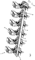
- multi-row seeder 1 has a transversely to the direction F extending telescopic frame 2, which is provided for receiving a plurality of working tools 3 designed as sowing units.
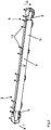
- the telescopic frame 2 comprises in the example chosen the Fig. 1 to 6 an outer tube section 4, in which left and right side each an inner tube section 5 is slidably mounted.
- the axial extent of the inner pipe sections 5 amounts to at least approximately half of the axial extent of the outer pipe section 4.
- the telescopic frame 2 Due to the slidable mounting of the inner pipe sections 5 within the outer pipe section 4 of the telescopic frame 2 between a fully telescoping transport position 6, shown in FIG Fig. 2 , and a telescoped working position 7, shown in FIG Fig. 3 , can be moved.
- the telescopic frame 2 is dimensioned such that it does not exceed a country-specific maximum permissible road transport width in its transport position 6.
- the width of the telescopic frame 2 is task-specific in its working position 7 depending on the adjustable mutual distance of the recorded work tools 3, but limited to at least approximately twice the axial extent of the outer tube section 4.
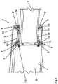
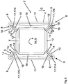
- the outer pipe section 4 has an at least approximately H-shaped cross-sectional profile, as shown in the Fig. 4 and 6 is shown.
- the H-shaped cross-sectional profile includes projections 8 which are arranged on the four axially extending edges of the outer tube section 4.
- the projections 8 are formed as wedge-shaped grooves and each have an upright side surface 9 and a sloping side surface 10.
- each projection 8 forms part of the upright side surface 11 of the outer tube section 4, wherein the upstanding side surfaces 11 of the outer tube section 4 in the example of Fig. 1 to 6 are arranged on the front in the direction of travel F and rear side of the outer tube section 4.
- the sloping side surfaces 10 of the projections 8 begin at the upper and lower ends of the upstanding side surfaces 11 of the outer tube section 4 and then extend obliquely toward the longitudinal axis of the outer tube section 4 until it on the horizontally extending, upper and lower side surfaces 12 of the meet outer pipe section 4.
- the sloping side surfaces 10 of the projections 8 are arranged on the upper and lower sides of the outer tube section 4 and converge towards each other.
- the projections 8 are wedge-shaped or triangular.
- trapezoidal projections 8 are also possible.
- the obliquely sloping side surfaces 10 of the projections 8 would not meet directly on the horizontally extending side surfaces 12 of the outer tube section 4 but be connected to them via a respective, not shown, upright side surface of the projections 8.
- the upstanding side surfaces 11 of the outer tube section 4 have by their extension to the upstanding side surfaces 9 of the projections 8 a larger area than the horizontally extending side surfaces 12 of the outer tube section 4.
- the upstanding side surfaces 11 of the outer tube section 4 in vertical direction greater dimensions than the horizontally extending side surfaces 12th
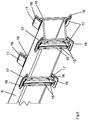
- a plurality of working tools 3 designed as sowing units are fastened to the outer pipe section 4 at a distance from each other.
- the carrying devices 13 have suitable recesses, by means of which they are hooked from above into the projections 8 of the outer tube section 4.
- the carrying devices 13 rest on the outer sides 14 of the projections 8 facing them and on the upright side surface 11 of the outer tube section 4 connecting them to the projections 8 facing them.
- the focus of the attached in the manner described working tools 3 is outside of the outer tube section 4.
- weight of the working tools 3 generates a torque which acts on the outer tube section 4 and causes a torsional force TA of the outer tube section 4.
- the outer pipe section 4 is very insensitive due to its caused by the H-shaped cross section high area moment of inertia. As a result, the outer pipe section 4 is very dimensionally stable.
- the inside of the outer tube section 4 slidably mounted inner tube sections 5 have a square profile, as it 4 to 6 demonstrate.
- the square sections having inner pipe sections 5 are positively and rotatably connected to connecting elements 16.
- the interconnected with connecting elements 16 inner pipe sections 5 are based on sliding elements 17 against the inner sides 18 of the sloping side surfaces 10 of the projections 8 from how Fig. 6 shows.
- the sliding elements 17 are detachably fastened to the connecting elements 16 and consist of a material which has a lower sliding friction with respect to the inner sides 18 of the outer tube section 4 than the connecting elements 16.
- the sliding elements 17 serve to improve the sliding properties between the inner tube sections 5 and the outer tube section 4.
- the dimensions of the projections 8 of the outer tube section 4, the connecting elements 16 and the sliding elements are selected such that the bearing surfaces 19 of the connecting elements 16 parallel to the sloping side surfaces 10, in particular to the inner sides 18 of the sloping side surfaces 10, the projections 8 extend ,
- the sliding elements 17 are arranged. They preferably have a greater extent in the longitudinal direction of the outer tube section 4 than in the direction perpendicular to this longitudinal direction.
- the sliding elements 17 rest over the entire surface on the inner sides 18 of the sloping side surfaces 10 of the projections.
- the full-surface system ensures a uniform over the entire surface of the sliding elements 17 power transmission and prevents uneven wear of the sliding elements 17th
- the weight force of the inner pipe sections 5 acts in the direction of gravity G and is introduced into the outer pipe section 4 via the two lower sliding elements 17A, 17B.
- austeleskopierter working position 7 of the telescopic frame 2 causes the one-sided storage of the inner pipe sections 5 within the outer tube section 4 bending forces, as it is generally known by gravity in cantilever beams.
- the one-sided mounting of the inner pipe sections 5 within the outer pipe section 4 results in attacking bending forces to a leverage. Due to the leverage effect, the acting bending forces are divided into a component acting in the direction of gravity G and in a component acting counter to the direction of gravity G.
- the force acting in the direction of gravity G component of the bending forces is introduced analogously to the weight of the inner pipe sections 5 via the lower sliding elements 17A, 17B down into the outer pipe section 4.
- the opposite to the direction of gravity G acting component of the bending forces is introduced via the upper sliding elements 17C, 17D upwards into the outer tube section.
- Both components of the bending forces act in vertical direction.
- the outer tube section 4 in the vertical direction on a particularly large axial moment of area moment of inertia.
- This large axial area moment of inertia in the vertical direction causes a particularly great dimensional stability and insensitivity of the outer tube section 4 against forces acting in the vertical direction.
- each inner tube section 5 of the telescopic frame 2 is assigned at least one working tool 3 in each case.
- a working tool 3 is attached to the outer end of the inner pipe sections 5 in the selected embodiment.
- the center of gravity of the working tools 3 secured to the inner pipe sections 5 causes a force acting on the inner pipe sections 5 to act on the inner pipe sections 5 by the weight force of the work tools 3 acting in the direction of gravity G.
- the torque acting on the inner pipe sections 5 generates a torsional force TI acting on the inner pipe sections 5.
- the torsion force TI acting on the inner pipe sections 5 leads to a loading of the inner pipe sections 5, which rotates the inner pipe sections 5 against the outer pipe section 4. This rotation is prevented by the means of the connecting elements 16 and the sliding elements 17 ensured positive storage of the inner pipe sections 5 within the outer pipe section 4.
- the torsional forces TI acting on the inner tube sections 5 are introduced into the projections 8 of the outer tube section 4 via diagonally opposite equalizing elements 17B and 17C.
- the torsional forces TI acting on the inner pipe sections 5 are divided into a substantially downwardly directed component TIu and a substantially upwardly directed component TIo, as described in US Pat Fig. 6 are shown.
- the dimensions of the sloping side surfaces 10 of the projections 8 and the connecting elements 16th chosen such that the torsional forces TI, TIu, TIo to be introduced into the projections 8 are introduced at least approximately vertically into the sloping side surfaces 10 of the projections 8.
- the sliding elements 17,17 B, 17 C over the entire surface of the inner sides 18 of the sloping side surfaces 10 of the projections 8 at.
- a uniform and especially full-surface power transmission between the inner pipe sections 5 and the outer pipe section 4 is achieved, which prevents uneven wear of the sliding elements 17 and reduces the sliding friction occurring.
Landscapes
- Life Sciences & Earth Sciences (AREA)
- Soil Sciences (AREA)
- Environmental Sciences (AREA)
- Engineering & Computer Science (AREA)
- Mechanical Engineering (AREA)
- Earth Drilling (AREA)
Claims (11)
- Semoir mono-graine à plusieurs rangées (1) comprenant un cadre qui comporte au moins un élément de cadre (2) disposé transversalement au sens de roulement (F) et réglable de manière télescopique dans le sens de sa longueur, l'au moins un élément de cadre (2) étant associé à une pluralité d'outils de travail (3) conçus par exemple sous la forme d'unités d'ensemencement et l'au moins un élément de cadre (2) comprenant une partie tubulaire extérieure (4) et au moins une partie tubulaire intérieure (5), l'au moins une partie tubulaire intérieure (5) étant montée de manière coulissante dans la partie tubulaire extérieure (4), au moins la partie tubulaire extérieure (4) ayant un profil en coupe transversale au moins à peu près en forme de H, caractérisé en ce que les saillies (8) du profil en coupe transversale en forme de H sont conçues comme des gorges en forme de coin, et l'au moins une partie tubulaire intérieure (5) étant guidée par complémentarité de formes à l'intérieur de la partie tubulaire extérieure (4) au moyen d'éléments coulissants (17), les éléments coulissants (17) venant en appui sur les surfaces intérieures (18) des saillies (8) en forme de coin du profil en coupe transversale au moins à peu près en forme de H de la partie tubulaire extérieure (4).
- Semoir mono-graine (1) selon la revendication 1, caractérisé en ce que les saillies (8) en forme de coin du profil en coupe transversale au moins à peu près en forme de H de la partie tubulaire extérieure (4) comportent des surfaces latérales (10) s'étendant obliquement depuis les bords extérieurs de la partie tubulaire extérieure (4) en direction du centre des surfaces latérales (12) de la partie tubulaire extérieure (4).
- Semoir mono-graine (1) selon l'une au moins des revendications précédentes,
caractérisé en ce que les surfaces latérales (10), s'étendant obliquement, des saillies (8) de la partie tubulaire extérieure (4) comportent des côtés intérieurs (18) et des côtés extérieurs (14) qui s'étendent parallèlement entre eux. - Semoir mono-graine (1) selon l'une au moins des revendications précédentes,
caractérisé en ce qu'une saillie (8), conçue sous la forme d'une gorge en forme de coin, est disposée au niveau des quatre bords d'au moins la partie tubulaire extérieure (4). - Semoir mono-graine (1) selon l'une au moins des revendications précédentes,
caractérisé en ce que les surfaces latérales (10), s'étendant obliquement, des saillies (8) en forme de coin sont disposées sur les côtés supérieur et inférieur de la partie tubulaire extérieure. - Semoir mono-graine (1) selon l'une au moins des revendications précédentes,
caractérisé en ce que les surfaces latérales (10), s'étendant obliquement, sont au moins à peu près convergentes. - Semoir mono-graine (1) selon l'une au moins des revendications précédentes,
caractérisé en ce que l'au moins une partie tubulaire intérieure (5) est centrée à l'intérieur de la partie tubulaire extérieure (4) par guidage par complémentarité de formes au moyen des éléments coulissants (17). - Semoir mono-graine (1) selon l'une au moins des revendications précédentes,
caractérisé en ce que les éléments coulissants (17) viennent en appui au moins à peu près sur toute l'étendue des surfaces intérieures (18) des saillies (8) du profilé en coupe transversale au moins à peu près en forme de H de la partie tubulaire extérieure (4) . - Semoir mono-graine (1) selon l'une au moins des revendications précédentes,
caractérisé en ce que les éléments coulissants (17) viennent en appui au moins à peu près sur toute l'étendue des surfaces intérieures (18) des surfaces latérales (10), obliquement convergentes, des saillies (8) du profil en coupe transversale au moins à peu près en forme de H de la partie tubulaire extérieure (4). - Semoir mono-graine (1) selon l'une au moins des revendications précédentes,
caractérisé en ce que, lors de la rotation de l'au moins une partie tubulaire intérieure (5) vers la partie tubulaire extérieure (4), l'au moins une partie tubulaire intérieure (5) s'appuie par le biais des éléments coulissants (17) contre le côté intérieur (18) des surfaces latérales convergentes (10) des saillies (8) en forme de coin du profil en coupe transversale au moins à peu près en forme de H de la partie tubulaire extérieure (4). - Semoir mono-graine (1) selon la revendication 7,
caractérisé en ce que les dimensions et/ou l'angle intérieur des saillies (8) en forme de coin sont choisis en fonction des dimensions des parties tubulaires extérieures et intérieures (4) de telle sorte que, lors de la torsion (TI) de l'au moins une partie tubulaire intérieure (5), des forces de torsion s'exerçant autour de l'axe longitudinal commun de la partie tubulaire extérieure (4) et d'au moins une partie tubulaire intérieure (5) soient injectées au moins à peu près perpendiculairement dans les surfaces intérieures (18) des saillies (8) en forme de coin de la partie tubulaire extérieure (4).
Priority Applications (1)
| Application Number | Priority Date | Filing Date | Title |
|---|---|---|---|
| PL17401121T PL3335533T3 (pl) | 2016-12-13 | 2017-12-07 | Wielorzędowy siewnik precyzyjny z ramą teleskopową |
Applications Claiming Priority (1)
| Application Number | Priority Date | Filing Date | Title |
|---|---|---|---|
| DE102016124131.8A DE102016124131A1 (de) | 2016-12-13 | 2016-12-13 | Mehrreihige Einzelkornsämaschine mit Teleskoprahmen |
Publications (2)
| Publication Number | Publication Date |
|---|---|
| EP3335533A1 EP3335533A1 (fr) | 2018-06-20 |
| EP3335533B1 true EP3335533B1 (fr) | 2019-09-11 |
Family
ID=60812000
Family Applications (1)
| Application Number | Title | Priority Date | Filing Date |
|---|---|---|---|
| EP17401121.3A Active EP3335533B1 (fr) | 2016-12-13 | 2017-12-07 | Semoir monograine à plusieurs rangées à cadre télescopique |
Country Status (3)
| Country | Link |
|---|---|
| EP (1) | EP3335533B1 (fr) |
| DE (1) | DE102016124131A1 (fr) |
| PL (1) | PL3335533T3 (fr) |
Families Citing this family (1)
| Publication number | Priority date | Publication date | Assignee | Title |
|---|---|---|---|---|
| DE102018120805B4 (de) | 2018-08-27 | 2021-06-10 | Amazonen-Werke H. Dreyer SE & Co. KG | Landwirtschaftliche Maschine mit Teleskoprahmen |
Family Cites Families (8)
| Publication number | Priority date | Publication date | Assignee | Title |
|---|---|---|---|---|
| US4112649A (en) * | 1977-08-26 | 1978-09-12 | Harnischfeger Corporation | Boom section for telescopic crane boom |
| DE4138237C2 (de) | 1991-11-21 | 1994-08-25 | Kleine Franz Maschf | Teleskoprahmen einer landwirtschaftlichen Maschine |
| DE29908130U1 (de) * | 1999-05-06 | 1999-08-12 | Herbert Grüttner GmbH & Co KG, 32683 Barntrup | Teleskopsäule |
| US7775167B2 (en) * | 2006-08-22 | 2010-08-17 | Monsanto Technology Llc | Custom planter and method of custom planting |
| FR2920266B1 (fr) * | 2007-08-30 | 2009-11-20 | Kuhn Sa | Chassis telescopique ameliore et appareil agricole avec un tel chassis |
| CN202889916U (zh) * | 2012-08-27 | 2013-04-24 | 哈尔滨伴农机械制造有限公司 | 气吸式免耕精量播种机 |
| DE102016105650A1 (de) * | 2016-03-29 | 2017-10-05 | Amazonen-Werke H. Dreyer Gmbh & Co. Kg | Querbalken zum Befestigen und Tragen von Werkzeugen eines landwirtschaftlichen Gerätes |
| DE102016106353A1 (de) * | 2016-04-07 | 2017-10-12 | Amazonen-Werke H. Dreyer Gmbh & Co. Kg | Vorrichtung zur Befestigung eines Werkzeugs an einem Rahmen |
-
2016
- 2016-12-13 DE DE102016124131.8A patent/DE102016124131A1/de not_active Withdrawn
-
2017
- 2017-12-07 EP EP17401121.3A patent/EP3335533B1/fr active Active
- 2017-12-07 PL PL17401121T patent/PL3335533T3/pl unknown
Non-Patent Citations (1)
| Title |
|---|
| None * |
Also Published As
| Publication number | Publication date |
|---|---|
| DE102016124131A1 (de) | 2018-06-14 |
| EP3335533A1 (fr) | 2018-06-20 |
| PL3335533T3 (pl) | 2020-03-31 |
Similar Documents
| Publication | Publication Date | Title |
|---|---|---|
| EP3344480B1 (fr) | Dispositif de suspension de bâche | |
| DE68906457T2 (de) | Aufhängungseinrichtung mit einem Nockenunterstützungselement. | |
| EP2152113B1 (fr) | Parasol à bras libre | |
| DE2616859A1 (de) | Teleskop-ausleger | |
| EP2513391B1 (fr) | Étai télescopique pour le secteur de la construction | |
| DE202009003633U1 (de) | Vorrichtung zur Befestigung von Balken und anderen Bauteilen | |
| EP2983943A1 (fr) | Dispositif de réglage longitudinal d'un siège de véhicule et siège de véhicule | |
| DE3011212A1 (de) | Heuwerbungsmaschine | |
| EP3564182B1 (fr) | Pompe à béton automatique | |
| DE102008024132B4 (de) | Spoilerantrieb mit Zwischenstellungen | |
| WO2016120303A1 (fr) | Dispositif de protection de charges | |
| EP3718823B1 (fr) | Dispositif de maintien d'une extrémité d'un objet oblong, en particulier une charge autoportante ainsi que véhicule utilisant un tel dispositif | |
| EP3335533B1 (fr) | Semoir monograine à plusieurs rangées à cadre télescopique | |
| DE8716609U1 (de) | Wagenheber | |
| WO2011073064A1 (fr) | Étai télescopique | |
| DE202008007467U1 (de) | Abstützvorrichtung, insbesondere Unterstellbock | |
| EP4263412B1 (fr) | Construction de support | |
| DE102006035915A1 (de) | Hubeinrichtung | |
| DE102018003413A1 (de) | Sportbarren | |
| EP2965602B1 (fr) | Semoir | |
| DE102017001128B4 (de) | Abstützung für einen Kran | |
| EP3812601B1 (fr) | Pièce façonnée, système de sécurité contre le déplacement pourvu de pièce façonnée, machine de travail agricole pourvue de système de sécurité contre le déplacement et procédé de montage du système de sécurité contre le déplacement | |
| EP3862636B1 (fr) | Système d'extension avec un rail télescopique | |
| EP3756436B1 (fr) | Relevage avant ainsi que machine de travail doté d'un relevage avant | |
| EP3718822B1 (fr) | Support de charge pour un véhicule de transport pour charges lourdes, en particulier une remorque de transport pour charges lourdes, ainsi que véhicule de transport pour charges lourdes comportant un tel support de charge |
Legal Events
| Date | Code | Title | Description |
|---|---|---|---|
| PUAI | Public reference made under article 153(3) epc to a published international application that has entered the european phase |
Free format text: ORIGINAL CODE: 0009012 |
|
| STAA | Information on the status of an ep patent application or granted ep patent |
Free format text: STATUS: THE APPLICATION HAS BEEN PUBLISHED |
|
| AK | Designated contracting states |
Kind code of ref document: A1 Designated state(s): AL AT BE BG CH CY CZ DE DK EE ES FI FR GB GR HR HU IE IS IT LI LT LU LV MC MK MT NL NO PL PT RO RS SE SI SK SM TR |
|
| AX | Request for extension of the european patent |
Extension state: BA ME |
|
| STAA | Information on the status of an ep patent application or granted ep patent |
Free format text: STATUS: REQUEST FOR EXAMINATION WAS MADE |
|
| 17P | Request for examination filed |
Effective date: 20181210 |
|
| RBV | Designated contracting states (corrected) |
Designated state(s): AL AT BE BG CH CY CZ DE DK EE ES FI FR GB GR HR HU IE IS IT LI LT LU LV MC MK MT NL NO PL PT RO RS SE SI SK SM TR |
|
| GRAP | Despatch of communication of intention to grant a patent |
Free format text: ORIGINAL CODE: EPIDOSNIGR1 |
|
| STAA | Information on the status of an ep patent application or granted ep patent |
Free format text: STATUS: GRANT OF PATENT IS INTENDED |
|
| INTG | Intention to grant announced |
Effective date: 20190523 |
|
| GRAS | Grant fee paid |
Free format text: ORIGINAL CODE: EPIDOSNIGR3 |
|
| GRAA | (expected) grant |
Free format text: ORIGINAL CODE: 0009210 |
|
| STAA | Information on the status of an ep patent application or granted ep patent |
Free format text: STATUS: THE PATENT HAS BEEN GRANTED |
|
| AK | Designated contracting states |
Kind code of ref document: B1 Designated state(s): AL AT BE BG CH CY CZ DE DK EE ES FI FR GB GR HR HU IE IS IT LI LT LU LV MC MK MT NL NO PL PT RO RS SE SI SK SM TR |
|
| REG | Reference to a national code |
Ref country code: GB Ref legal event code: FG4D Free format text: NOT ENGLISH |
|
| REG | Reference to a national code |
Ref country code: CH Ref legal event code: EP |
|
| REG | Reference to a national code |
Ref country code: AT Ref legal event code: REF Ref document number: 1177280 Country of ref document: AT Kind code of ref document: T Effective date: 20190915 |
|
| REG | Reference to a national code |
Ref country code: DE Ref legal event code: R096 Ref document number: 502017002282 Country of ref document: DE |
|
| REG | Reference to a national code |
Ref country code: IE Ref legal event code: FG4D Free format text: LANGUAGE OF EP DOCUMENT: GERMAN |
|
| REG | Reference to a national code |
Ref country code: SE Ref legal event code: TRGR |
|
| REG | Reference to a national code |
Ref country code: NL Ref legal event code: MP Effective date: 20190911 |
|
| REG | Reference to a national code |
Ref country code: LT Ref legal event code: MG4D |
|
| PG25 | Lapsed in a contracting state [announced via postgrant information from national office to epo] |
Ref country code: FI Free format text: LAPSE BECAUSE OF FAILURE TO SUBMIT A TRANSLATION OF THE DESCRIPTION OR TO PAY THE FEE WITHIN THE PRESCRIBED TIME-LIMIT Effective date: 20190911 Ref country code: NO Free format text: LAPSE BECAUSE OF FAILURE TO SUBMIT A TRANSLATION OF THE DESCRIPTION OR TO PAY THE FEE WITHIN THE PRESCRIBED TIME-LIMIT Effective date: 20191211 Ref country code: HR Free format text: LAPSE BECAUSE OF FAILURE TO SUBMIT A TRANSLATION OF THE DESCRIPTION OR TO PAY THE FEE WITHIN THE PRESCRIBED TIME-LIMIT Effective date: 20190911 Ref country code: LT Free format text: LAPSE BECAUSE OF FAILURE TO SUBMIT A TRANSLATION OF THE DESCRIPTION OR TO PAY THE FEE WITHIN THE PRESCRIBED TIME-LIMIT Effective date: 20190911 Ref country code: BG Free format text: LAPSE BECAUSE OF FAILURE TO SUBMIT A TRANSLATION OF THE DESCRIPTION OR TO PAY THE FEE WITHIN THE PRESCRIBED TIME-LIMIT Effective date: 20191211 |
|
| PG25 | Lapsed in a contracting state [announced via postgrant information from national office to epo] |
Ref country code: AL Free format text: LAPSE BECAUSE OF FAILURE TO SUBMIT A TRANSLATION OF THE DESCRIPTION OR TO PAY THE FEE WITHIN THE PRESCRIBED TIME-LIMIT Effective date: 20190911 Ref country code: LV Free format text: LAPSE BECAUSE OF FAILURE TO SUBMIT A TRANSLATION OF THE DESCRIPTION OR TO PAY THE FEE WITHIN THE PRESCRIBED TIME-LIMIT Effective date: 20190911 Ref country code: RS Free format text: LAPSE BECAUSE OF FAILURE TO SUBMIT A TRANSLATION OF THE DESCRIPTION OR TO PAY THE FEE WITHIN THE PRESCRIBED TIME-LIMIT Effective date: 20190911 Ref country code: GR Free format text: LAPSE BECAUSE OF FAILURE TO SUBMIT A TRANSLATION OF THE DESCRIPTION OR TO PAY THE FEE WITHIN THE PRESCRIBED TIME-LIMIT Effective date: 20191212 Ref country code: ES Free format text: LAPSE BECAUSE OF FAILURE TO SUBMIT A TRANSLATION OF THE DESCRIPTION OR TO PAY THE FEE WITHIN THE PRESCRIBED TIME-LIMIT Effective date: 20190911 |
|
| PG25 | Lapsed in a contracting state [announced via postgrant information from national office to epo] |
Ref country code: RO Free format text: LAPSE BECAUSE OF FAILURE TO SUBMIT A TRANSLATION OF THE DESCRIPTION OR TO PAY THE FEE WITHIN THE PRESCRIBED TIME-LIMIT Effective date: 20190911 Ref country code: PT Free format text: LAPSE BECAUSE OF FAILURE TO SUBMIT A TRANSLATION OF THE DESCRIPTION OR TO PAY THE FEE WITHIN THE PRESCRIBED TIME-LIMIT Effective date: 20200113 Ref country code: NL Free format text: LAPSE BECAUSE OF FAILURE TO SUBMIT A TRANSLATION OF THE DESCRIPTION OR TO PAY THE FEE WITHIN THE PRESCRIBED TIME-LIMIT Effective date: 20190911 Ref country code: EE Free format text: LAPSE BECAUSE OF FAILURE TO SUBMIT A TRANSLATION OF THE DESCRIPTION OR TO PAY THE FEE WITHIN THE PRESCRIBED TIME-LIMIT Effective date: 20190911 |
|
| PG25 | Lapsed in a contracting state [announced via postgrant information from national office to epo] |
Ref country code: CZ Free format text: LAPSE BECAUSE OF FAILURE TO SUBMIT A TRANSLATION OF THE DESCRIPTION OR TO PAY THE FEE WITHIN THE PRESCRIBED TIME-LIMIT Effective date: 20190911 Ref country code: SM Free format text: LAPSE BECAUSE OF FAILURE TO SUBMIT A TRANSLATION OF THE DESCRIPTION OR TO PAY THE FEE WITHIN THE PRESCRIBED TIME-LIMIT Effective date: 20190911 Ref country code: SK Free format text: LAPSE BECAUSE OF FAILURE TO SUBMIT A TRANSLATION OF THE DESCRIPTION OR TO PAY THE FEE WITHIN THE PRESCRIBED TIME-LIMIT Effective date: 20190911 Ref country code: IS Free format text: LAPSE BECAUSE OF FAILURE TO SUBMIT A TRANSLATION OF THE DESCRIPTION OR TO PAY THE FEE WITHIN THE PRESCRIBED TIME-LIMIT Effective date: 20200224 |
|
| REG | Reference to a national code |
Ref country code: DE Ref legal event code: R097 Ref document number: 502017002282 Country of ref document: DE |
|
| PLBE | No opposition filed within time limit |
Free format text: ORIGINAL CODE: 0009261 |
|
| STAA | Information on the status of an ep patent application or granted ep patent |
Free format text: STATUS: NO OPPOSITION FILED WITHIN TIME LIMIT |
|
| PG2D | Information on lapse in contracting state deleted |
Ref country code: IS |
|
| PG25 | Lapsed in a contracting state [announced via postgrant information from national office to epo] |
Ref country code: DK Free format text: LAPSE BECAUSE OF FAILURE TO SUBMIT A TRANSLATION OF THE DESCRIPTION OR TO PAY THE FEE WITHIN THE PRESCRIBED TIME-LIMIT Effective date: 20190911 Ref country code: IS Free format text: LAPSE BECAUSE OF FAILURE TO SUBMIT A TRANSLATION OF THE DESCRIPTION OR TO PAY THE FEE WITHIN THE PRESCRIBED TIME-LIMIT Effective date: 20200112 |
|
| 26N | No opposition filed |
Effective date: 20200615 |
|
| REG | Reference to a national code |
Ref country code: BE Ref legal event code: MM Effective date: 20191231 |
|
| PG25 | Lapsed in a contracting state [announced via postgrant information from national office to epo] |
Ref country code: MC Free format text: LAPSE BECAUSE OF FAILURE TO SUBMIT A TRANSLATION OF THE DESCRIPTION OR TO PAY THE FEE WITHIN THE PRESCRIBED TIME-LIMIT Effective date: 20190911 Ref country code: SI Free format text: LAPSE BECAUSE OF FAILURE TO SUBMIT A TRANSLATION OF THE DESCRIPTION OR TO PAY THE FEE WITHIN THE PRESCRIBED TIME-LIMIT Effective date: 20190911 |
|
| PG25 | Lapsed in a contracting state [announced via postgrant information from national office to epo] |
Ref country code: IE Free format text: LAPSE BECAUSE OF NON-PAYMENT OF DUE FEES Effective date: 20191207 Ref country code: LU Free format text: LAPSE BECAUSE OF NON-PAYMENT OF DUE FEES Effective date: 20191207 |
|
| PG25 | Lapsed in a contracting state [announced via postgrant information from national office to epo] |
Ref country code: BE Free format text: LAPSE BECAUSE OF NON-PAYMENT OF DUE FEES Effective date: 20191231 |
|
| REG | Reference to a national code |
Ref country code: DE Ref legal event code: R081 Ref document number: 502017002282 Country of ref document: DE Owner name: AMAZONEN-WERKE H. DREYER SE & CO. KG, DE Free format text: FORMER OWNER: AMAZONEN-WERKE H. DREYER GMBH & CO. KG, 49205 HASBERGEN, DE |
|
| PG25 | Lapsed in a contracting state [announced via postgrant information from national office to epo] |
Ref country code: CY Free format text: LAPSE BECAUSE OF FAILURE TO SUBMIT A TRANSLATION OF THE DESCRIPTION OR TO PAY THE FEE WITHIN THE PRESCRIBED TIME-LIMIT Effective date: 20190911 |
|
| PG25 | Lapsed in a contracting state [announced via postgrant information from national office to epo] |
Ref country code: MT Free format text: LAPSE BECAUSE OF FAILURE TO SUBMIT A TRANSLATION OF THE DESCRIPTION OR TO PAY THE FEE WITHIN THE PRESCRIBED TIME-LIMIT Effective date: 20190911 Ref country code: HU Free format text: LAPSE BECAUSE OF FAILURE TO SUBMIT A TRANSLATION OF THE DESCRIPTION OR TO PAY THE FEE WITHIN THE PRESCRIBED TIME-LIMIT; INVALID AB INITIO Effective date: 20171207 |
|
| REG | Reference to a national code |
Ref country code: CH Ref legal event code: PL |
|
| PG25 | Lapsed in a contracting state [announced via postgrant information from national office to epo] |
Ref country code: LI Free format text: LAPSE BECAUSE OF NON-PAYMENT OF DUE FEES Effective date: 20201231 Ref country code: CH Free format text: LAPSE BECAUSE OF NON-PAYMENT OF DUE FEES Effective date: 20201231 |
|
| PG25 | Lapsed in a contracting state [announced via postgrant information from national office to epo] |
Ref country code: TR Free format text: LAPSE BECAUSE OF FAILURE TO SUBMIT A TRANSLATION OF THE DESCRIPTION OR TO PAY THE FEE WITHIN THE PRESCRIBED TIME-LIMIT Effective date: 20190911 |
|
| PG25 | Lapsed in a contracting state [announced via postgrant information from national office to epo] |
Ref country code: MK Free format text: LAPSE BECAUSE OF FAILURE TO SUBMIT A TRANSLATION OF THE DESCRIPTION OR TO PAY THE FEE WITHIN THE PRESCRIBED TIME-LIMIT Effective date: 20190911 |
|
| GBPC | Gb: european patent ceased through non-payment of renewal fee |
Effective date: 20211207 |
|
| PG25 | Lapsed in a contracting state [announced via postgrant information from national office to epo] |
Ref country code: GB Free format text: LAPSE BECAUSE OF NON-PAYMENT OF DUE FEES Effective date: 20211207 |
|
| P01 | Opt-out of the competence of the unified patent court (upc) registered |
Effective date: 20230523 |
|
| PGFP | Annual fee paid to national office [announced via postgrant information from national office to epo] |
Ref country code: PL Payment date: 20250912 Year of fee payment: 9 |
|
| PGFP | Annual fee paid to national office [announced via postgrant information from national office to epo] |
Ref country code: FR Payment date: 20250930 Year of fee payment: 9 |
|
| PGFP | Annual fee paid to national office [announced via postgrant information from national office to epo] |
Ref country code: DE Payment date: 20250930 Year of fee payment: 9 |
|
| PGFP | Annual fee paid to national office [announced via postgrant information from national office to epo] |
Ref country code: AT Payment date: 20251126 Year of fee payment: 9 |
|
| PGFP | Annual fee paid to national office [announced via postgrant information from national office to epo] |
Ref country code: IT Payment date: 20251121 Year of fee payment: 9 |
|
| PGFP | Annual fee paid to national office [announced via postgrant information from national office to epo] |
Ref country code: SE Payment date: 20251001 Year of fee payment: 9 |