EP3335554A1 - Pulvérisateur à cultures - Google Patents
Pulvérisateur à cultures Download PDFInfo
- Publication number
- EP3335554A1 EP3335554A1 EP17401122.1A EP17401122A EP3335554A1 EP 3335554 A1 EP3335554 A1 EP 3335554A1 EP 17401122 A EP17401122 A EP 17401122A EP 3335554 A1 EP3335554 A1 EP 3335554A1
- Authority
- EP
- European Patent Office
- Prior art keywords
- distributor
- field sprayer
- lighting units
- sprayer according
- light
- Prior art date
- Legal status (The legal status is an assumption and is not a legal conclusion. Google has not performed a legal analysis and makes no representation as to the accuracy of the status listed.)
- Withdrawn
Links
Images



Classifications
-
- A—HUMAN NECESSITIES
- A01—AGRICULTURE; FORESTRY; ANIMAL HUSBANDRY; HUNTING; TRAPPING; FISHING
- A01M—CATCHING, TRAPPING OR SCARING OF ANIMALS; APPARATUS FOR THE DESTRUCTION OF NOXIOUS ANIMALS OR NOXIOUS PLANTS
- A01M7/00—Special adaptations or arrangements of liquid-spraying apparatus for purposes covered by this subclass
- A01M7/005—Special arrangements or adaptations of the spraying or distributing parts, e.g. adaptations or mounting of the spray booms, mounting of the nozzles, protection shields
-
- A—HUMAN NECESSITIES
- A01—AGRICULTURE; FORESTRY; ANIMAL HUSBANDRY; HUNTING; TRAPPING; FISHING
- A01M—CATCHING, TRAPPING OR SCARING OF ANIMALS; APPARATUS FOR THE DESTRUCTION OF NOXIOUS ANIMALS OR NOXIOUS PLANTS
- A01M7/00—Special adaptations or arrangements of liquid-spraying apparatus for purposes covered by this subclass
- A01M7/005—Special arrangements or adaptations of the spraying or distributing parts, e.g. adaptations or mounting of the spray booms, mounting of the nozzles, protection shields
- A01M7/006—Mounting of the nozzles
-
- A—HUMAN NECESSITIES
- A01—AGRICULTURE; FORESTRY; ANIMAL HUSBANDRY; HUNTING; TRAPPING; FISHING
- A01M—CATCHING, TRAPPING OR SCARING OF ANIMALS; APPARATUS FOR THE DESTRUCTION OF NOXIOUS ANIMALS OR NOXIOUS PLANTS
- A01M7/00—Special adaptations or arrangements of liquid-spraying apparatus for purposes covered by this subclass
- A01M7/0089—Regulating or controlling systems
Definitions
- the invention relates to a field sprayer according to the preamble of claim 1 and as known from the EP 1 961 300 B1 ,
- Generic field sprayers are used in agriculture for spreading pesticides and allow by lighting the ejected fluid compartments a simple, reliable and energy-efficient control of Ausbringarbeit even in the dark. For example, it can be seen whether liquid is dispensed from the distributor nozzles, and whether there are obstacles at the free ends of the distributor linkage.
- LED light-emitting diodes
- LED can be used, which can be supplied by means extending in the distribution link lines with voltage and controlled by a CAN bus or the like.
- nozzle bodies with a comparatively small opening angle of the fluid fan generated should be used selectively in the edge region of a field and / or the distributor rod for a drift-reducing spraying.
- a field sprayer according to claim 1. Accordingly, this comprises at a manifold linkage spaced apart distribution nozzles, which lighting units are assigned to illuminate a respectively ejected from the distribution nozzles liquid fan. According to the invention, the lighting units have a light emission which can be switched over with regard to spectral, temporal and / or directional radiation characteristics as a function of operational and / or fault states of the distributor nozzles.
- At least one specific radiation characteristic of the lighting units for selectively displaying different correct operating states and / or specific fault states of the respectively activated distributor nozzles can be selectively changed.
- An assignment of the illumination units to the distributor nozzles is to be understood as an arrangement in which at least upper, non-overlapping areas of the fluid compartments can be separately illuminated, ie distinguishable from the illumination of adjacent fluid compartments.
- An error condition is, for example, an insufficient or missing fluid fan due to contamination or a defect in the area of the distributor nozzle.
- a proper operating state is, for example, the liquid ejection by means of a specific nozzle body present at the distributor nozzle, which is decisive for the characteristic of the generated liquid fan.
- the spectral, temporal and / or directional radiation characteristic can be switched, for example, by means of a central control on the field sprayer and / or by means of decentralized controls in the region of the distributor nozzles, if appropriate also by manual adjustment of the distributor nozzles, in particular for the use of a specific nozzle body.
- Different spectral emission characteristics in the sense of the present invention can be perceived by the human eye as different hues and / or as white light with a specific color temperature.
- the spectral emission characteristics are defined by corresponding regions of the visible light spectrum and / or corresponding spectral intensity distributions within such regions.
- Different hues and / or white light can be generated with individual light sources of different spectral radiation and / or by variable additive color mixing in a light source.
- the flashing lights may have different flashing patterns with different lengths of light and dark times, possibly also with suitable swelling and / or decaying light phases and dark phases.
- Different directional radiation characteristics are on the one hand the conventional main radiation direction for lighting down and on the other hand an additional or alternative radiation upward and / or to the side by means of light deflection and / or additional light sources.
- hues and flashing lights allow flexible coding of different operating states and / or fault conditions of the distributor nozzles during operation.
- Suitable illumination units comprise, for example, at least one multi-colored LED, with which a plurality of spectral and / or temporal emission characteristics can be generated for operating states and error states.
- Suitable illumination units may alternatively or additionally comprise at least one single-color LED for individual spectral and / or temporal illumination variants.
- the decisive factor is that the illumination units comprise light sources whose emission characteristic for individual active distribution nozzles can be changed in order to selectively display their current operating state and / or error state.
- the lighting units can be switched between at least two different shades.
- the color tones then preferably differ by at least 45 °, in particular by at least 60 °, in the HSV or HSI color space or the like from one another.
- the different shades are particularly suitable for identifying different proper operating conditions. Particularly suitable are, for example, blue, green and / or yellow shades, as well as white light. Red shades are particularly suitable for identifying fault conditions.
- the lighting units can be switched between continuous light and flashing light.
- the illumination may change from steady light to flashing light, and vice versa.
- Flashing light is suitable for particularly reliable identification of fault conditions, for example, even for color-blind persons.
- the relative bright times are preferably 10-90%.
- the length of the light and / or dark times can be, for example, 0.2 to 2 s. Flowing transitions between light phases and dark phases are possible in principle and defined, for example, at 50% brightness.
- Particularly advantageous is an identification of fault conditions by a change from steady light to flashing light and a change between hues or white light to another hue.
- a main emission direction of the illumination units can be switched over.
- the main radiation direction could point downwards in the correct operating state and upwards or sideways in the event of an error state. This could be achieved by deflecting optical elements, such as mirrors, or by targeted activation of appropriately aligned light sources.
- the field sprayer further comprises a controller for the lighting units for synchronized emission of a flashing light or running light for a group of distributor nozzles.
- a controller for the lighting units for synchronized emission of a flashing light or running light for a group of distributor nozzles.
- operating states or fault states can be identified jointly for a plurality of distributor nozzles, for example for the temporary marking of distributor nozzles during their activation and / or deactivation as part of a section control.
- the lighting units each comprise at least two separately switchable single-color LED and / or at least one multi-colored LED, ie an LED with adjustable color mixing. LEDs are particularly easy and flexible electrical control.
- the field sprayer further comprises monitoring units for monitoring the fluid compartments, in particular for optical monitoring of the illuminated fluid compartments, with regard to the occurrence of at least one fault condition.
- the monitoring units detect, for example, portions of the light rays deflected at the liquid compartments. If an impermissible deviation of the detected light from a target specification is detected, the illumination at the affected distributor nozzle changes to a radiation characteristic that identifies the detected fault condition. After the fault condition has been eliminated, the monitoring unit can be reset and the lighting unit can again be instructed to indicate the correct operating state.
- the field sprayer further comprises at least one controller for switching the radiation characteristic selectively for distributor nozzles in the fault state. This allows a direct and easy localization of operating conditions and / or fault conditions for all present at the manifold linkage distribution nozzles.
- the distributor nozzles each comprise at least two alternatively activatable nozzle bodies for ejecting different fluid compartments, wherein each nozzle body is assigned its own color shade for illuminating the fluid fan generated.
- This allows easy visual identification of the activated nozzle body for individual distribution nozzles. For example, it can be checked whether a nozzle body for a drift-reducing application of the spray agent was selected in the edge region of the distributor linkage.
- nozzle bodies which are particularly suitable for the interior of the field could be activated and correspondingly color-coded by illuminating the liquid compartments. Flashing lights would be possible in principle for coding certain nozzle body.
- the lighting units in the region of the nozzle body arranged and individually switchable single-color LED.
- the respectively assigned LED is automatically activated and the liquid fan generated by the active nozzle body is illuminated.
- Monochromatic LEDs are particularly energy efficient.
- the lighting units each comprise a plurality of nozzle bodies of the distributor nozzle jointly assigned multi-colored LED.
- Multi-colored LEDs can be color-coded and are therefore particularly flexible.
- the nozzle body are fastened together on adjustable holders, in particular turrets, with position sensors for detecting the respectively activated nozzle body and / or with tap changers for switching the associated hue.
- the nozzle bodies to be activated can then be manually rotated in a downwardly facing position. The selection of the activated nozzle body can be visually inspected on the basis of the consequently radiated hue, possibly also before the beginning of the application work.
- positioning motors for activating the nozzle body and a controller for automatically switching on the associated color tone are also formed on the field sprayer. This allows a central selection of certain nozzle body and their visual control, for example, from the driver's seat.
- the field sprayer 1 comprises a distributor linkage 2 extending transversely to the direction of travel and having segments 2a, 2b and 2c, at which a plurality of distributor nozzles 3 for ejecting liquid compartments 4 of a spray means are preferably arranged at regular intervals.
- Illuminating units 5 with a light emission 6 for illuminating the liquid compartments 4 are associated with the distributor nozzles 3.
- the light emission 6 and liquid compartments 4 are in the Fig. 1 shown only for every tenth distributor nozzle 3.
- the Fig. 2 illustrates the middle segment 2b of the distributor linkage 2 with the attached distributor nozzles 3 in normal working operation. Accordingly, all shown distributor nozzles 3 are operated so that they deliver identically designed fluid compartments 4.
- all illumination units 5 are operated to identify a specific operating state of the distributor nozzles 3 with identically designed light emission 6, ie with identical spectral emission characteristic 7, identical temporal emission characteristic 8 and identical directional emission characteristic 9.
- the spectral emission characteristic 7 is to be understood as meaning that the light emission 6 has a specific hue, for example a blue, green, yellow or red hue, which characterizes a specific operating state of the distributor nozzles 3. Different shades are represented by different hatch patterns. With regard to the function of the light emission 6, white light can also be understood as a separate color tone.
- the temporal emission characteristic 8 is to be understood as meaning that the illumination units 5 emit either permanent light perceived by the human eye as such or a flashing light with a flashing pattern recognizable by the human eye as such.
- Fig. 2 give all lighting units 5 permanent light. This is shown in the form of full surface hatching of the light emission 6.
- the directional radiation characteristic 9 is understood in particular to mean a main emission direction of the illumination units 5, which in the example of FIG Fig. 2 directed down to the fluid fan 4.
- the main emission direction of the illumination units 5 can be substantially parallel to the main ejection directions of the distributor nozzles 3 or they can be cut.
- the invention is based on the idea that at least one of the emission characteristics 7, 8, 9 for activated distributor nozzles 3 can be set manually or automatically and / or specifically changed in order to indicate specific operating states and / or error states of the distributor nozzles 3.
- first to fourth shades 7a-7d and continuous light 8a and 8b flashing light can be used.
- a normally used main emission direction 9a downwards could be selectively changed, for example, in a temporarily effective main emission direction 9b upward.
- the lighting units 5 preferably each comprise a plurality of individually switchable light sources, for example in the form of monochrome LED, and / or at least one light source with adjustable additive color mixing, in particular in the form of a multi-colored LED.
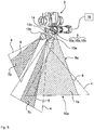
- the Fig. 3 shows by way of example the middle segment 2b of the distributor linkage 2 with distributor nozzles 3 operating properly in a first operating state 10a and a malfunctioning distributor nozzle 3a in an error state 11. This consists, for example, in the fact that the distributor nozzle 3a discharges no or insufficient liquid compartment 4.
- the assigned illumination unit 5 is preferably controlled in such a way that its spectral emission characteristic 7 and / or its temporal emission characteristic 8 changes in a targeted manner.
- the light emission 6 has a first color tone 7a in the first operating state 10a and a fourth color tone 7d in the error state 11. This is in the Fig. 3 characterized by different hatching patterns.
- the light emission 6 takes place in the first operating state as a continuous light 8a and in the error state 11 as a flashing light 8b with a characteristic flashing pattern. This is characterized by only hatching in sections of the illustrated light emission 6.
- the Fig. 4 illustrates for the outer segment 2c of the distributor linkage 2, that the distributor nozzles 3 can also be simultaneously in different proper operating states, namely for example in a second operating state 10b and in a third operating state 10c.
- the fluid compartments 4 have in the first operating state 10a, for example, the largest opening angle, in the second operating state 10b a middle and in the third operating state 10c an outwardly smaller opening angle.
- Certain proper operating conditions could also be defined in other ways, for example, by section switching or the like.
- the third operating state 10c was specifically selected, that is to say the liquid fan 4 with the opening angle reduced to the outside. This promotes a drift-reducing spraying in the lateral edge area.
- the other distributor nozzles 3 are, for example, in the second operating state 10b.
- the associated lighting units 5 preferably operate with correspondingly different spectral emission characteristics Fig. 4 the light emission 6 for the identification of distributor nozzles 3 in the second operating state 10b has a second color tone 7b and for the identification of the outer distributor nozzle 3b in the third operating state 10c a third color tone 7c.
- the lighting units 5 of distribution nozzles 3, 3b are operated continuously with proper operating conditions 10a-10c to illuminate the ejected liquid compartments 4 with continuous light 8a.
- flashing light 8b would also be conceivable.
- groups of distributor nozzles 3 could be identified in order to announce and / or confirm part-width switchings.
- the flashing light 8b could then be, for example, a running light along the distribution nozzles 3 respectively affected by the part width changeover, or the like.
- the Fig. 5 shows a distributor nozzle 3 with a plurality of alternatively usable nozzle bodies 13a, 13b, 13c for generating the liquid fan 4 according to operating state 10a, 10b or 10c.
- the nozzle bodies 13a, 13b, 13c are mounted, for example, on a common holder 14, which is designed, for example, as a revolver which can be rotated manually or by a motor, so that in each case only one of the nozzle bodies 13a, 13b, 13c is supplied with a spraying agent in a known manner.
- the in the Fig. 5 illustrated distributor nozzle 3 is in the first operating state 10a with activated nozzle body 13a.
- all the nozzle bodies 13a, 13b, 13c are shown with fluid compartments 4 and light emission 6.
- the lighting unit 5 assigned to the distributor nozzle 3 comprises, for example, separate light sources 15a, 15b, 15c which are respectively assigned to the individual nozzle bodies 13a, 13b, 13c.
- the separate light sources 15a, 15b, 15c are activated, for example, by rotating the holder 14 together with the associated nozzle bodies 13a, 13b, 13c.
- the separate light sources 15a, 15b, 15c preferably differ with regard to their spectral emission characteristic 7 and then have correspondingly different shades 7a, 7b, 7c.
- the light sources 15a, 15b, 15c are preferably LED and / or monochrome. Monochromatic LEDs are particularly energy efficient and available in different, visually distinguishable shades 7a, 7b, 7c.
- the respectively substantially vertically downwardly pointing nozzle body 13a is known to be supplied with spray.
- the light source 15a assigned to the nozzle body 13a can be produced, for example, by means of a position transmitter or tap changer present on the holder 14 (not shown) are automatically activated as soon as the associated nozzle body 13a has reached its active position.
- nozzle bodies 13a, 13b, 13c and the operating states 10a, 10b, 10c are thus automatically color-coded by the illumination of the liquid fan 4. This should be in the Fig. 5 be illustrated for all the nozzle body 13a, 13b, 13c shown fluid fan 4 and 6 light emission.
- a particular nozzle body 13a, 13b, 13c can be activated either manually by turning the holder 14 or by means of a servomotor.
- Associated light sources 15a, 15b, 15c can be switched on / off centrally by a control 16 (only schematically indicated) or decentralized, for example as described above.
- the Fig. 6 illustrates in detail the fault state 11, in which the active nozzle body 13a of the distributor nozzle 3 does not eject a fluid fan 4.
- the temporal radiation characteristic 8 of the associated lighting unit 5 changes from that in the Fig. 5 shown steady light 8a in a flashing light 8b with a suitable flashing pattern. This allows a reliable optical error message even in the dark.
- the error state 11 can also be changed by changing the spectral emission characteristic 7 of the associated illumination unit 5 from that in the Fig. 5 shown first hue 7a in the proper operating state 10a to a fourth hue 7d in the error state 11 are displayed.
- the illumination unit 5 can comprise at least one color-tunable light source 15d, in particular a multicolor LED, for displaying different operating and / or error states 10a, 10b, 10c, 11. This can be used in common for all the nozzle body 13a, 13b, 13c and is attached to the distributor nozzle 3 or to the distributor linkage 2.
- displaying the error state 11 by a red flashing light 8b would be particularly advantageous.
- the change from the steady light 8a to a blinking link 8b with a characteristic blinking pattern offers the advantage that even color-blind persons can easily recognize the error state 11.
- a monitoring unit (not shown) may be present in the region of each distributor nozzle 3, which detects, for example, a part of the light emission 6 deflected at the liquid fan 4. If the intensity of the light detected in this way falls below a predetermined threshold value, for example, an error state 11 at the distributor nozzle 3 can be assumed. The spectral, temporal and / or directional radiation characteristic 7, 8, 9 of the associated illumination unit 5 is then switched to display the error state 11, for example, by the controller 16 targeted.
- the lighting units 5 could for this purpose also include additional light sources (not shown) which indicate a fault condition 11 by a change, possibly also a supplement, of the directional radiation characteristic 9a. For example, in addition or as a substitute, light could be radiated upward to indicate or more clearly visualize the error condition 11. Nevertheless, in any case, the lighting units 5 are designed to illuminate the liquid compartments 4 at least in proper operating conditions 10a, 10b, 10c.
- the lighting units 5 are each assigned to separate distributor nozzles 3 and designed so that by means of targeted change of at least one emission characteristic 7, 8, 9 different operating conditions 10a, 10b, 10c and / or fault conditions 11 can be displayed separately for each assigned distribution nozzle 3.
- a plurality of lighting units 5 are controlled in groups by the controller 16 in order to display certain operating states for groups associated distributor nozzles 3, for example, at a connection or disconnection of distributor nozzles 3 in the context of a section control of the field sprayer 1 or the like.
- a plurality of lighting units 5 for generating flashing lights, running lights or the like can be synchronized. This may be done temporarily to alert the field sprayer driver to a change in work to be performed or performed.
- Control units 16 assigned to the distributor nozzles 3 and / or lighting units 5 can be present both centrally on the field sprayer 1 and decentrally in the area of the distributor nozzles 3.
- the electrical power supply of the lighting units 5 and / or their activation by means of a CAN bus or the like are conventional possible and therefore not further explained.
- the lighting units 5 can also be controlled by a music source and work as a light organ or the like.
Landscapes
- Life Sciences & Earth Sciences (AREA)
- Engineering & Computer Science (AREA)
- Insects & Arthropods (AREA)
- Pest Control & Pesticides (AREA)
- Wood Science & Technology (AREA)
- Zoology (AREA)
- Environmental Sciences (AREA)
- Catching Or Destruction (AREA)
- Spray Control Apparatus (AREA)
- Nozzles (AREA)
Applications Claiming Priority (1)
| Application Number | Priority Date | Filing Date | Title |
|---|---|---|---|
| DE102016124119.9A DE102016124119A1 (de) | 2016-12-13 | 2016-12-13 | Feldspritze |
Publications (1)
| Publication Number | Publication Date |
|---|---|
| EP3335554A1 true EP3335554A1 (fr) | 2018-06-20 |
Family
ID=60812001
Family Applications (1)
| Application Number | Title | Priority Date | Filing Date |
|---|---|---|---|
| EP17401122.1A Withdrawn EP3335554A1 (fr) | 2016-12-13 | 2017-12-07 | Pulvérisateur à cultures |
Country Status (2)
| Country | Link |
|---|---|
| EP (1) | EP3335554A1 (fr) |
| DE (1) | DE102016124119A1 (fr) |
Cited By (1)
| Publication number | Priority date | Publication date | Assignee | Title |
|---|---|---|---|---|
| WO2022090853A1 (fr) * | 2020-10-26 | 2022-05-05 | Precision Planting Llc | Ensemble lumière de buse |
Families Citing this family (2)
| Publication number | Priority date | Publication date | Assignee | Title |
|---|---|---|---|---|
| DE102018114669A1 (de) * | 2018-06-19 | 2019-12-19 | Amazonen-Werke H. Dreyer Gmbh & Co. Kg | Ausbringsystem für ein landwirtschaftliches Gerät |
| US11807157B2 (en) | 2020-06-30 | 2023-11-07 | Deere & Company | Method of controlling an agricultural vehicle lighting system and system thereof |
Citations (5)
| Publication number | Priority date | Publication date | Assignee | Title |
|---|---|---|---|---|
| EP1961300B1 (fr) | 2007-02-22 | 2011-03-30 | Amazonen-Werke H. Dreyer GmbH & Co. KG | Pulvérisateur agricole |
| EP2522432A1 (fr) * | 2011-05-10 | 2012-11-14 | Amazonen-Werke H. Dreyer GmbH & Co. KG | Corps à buses multiples avec éclairage |
| US20140048611A1 (en) * | 2012-08-20 | 2014-02-20 | Agco Corporation | Spray Nozzle Light |
| US20160044862A1 (en) * | 2014-08-14 | 2016-02-18 | Raven Industries, Inc. | Site specific product application device and method |
| EP3292749A1 (fr) * | 2016-09-09 | 2018-03-14 | Amazonen-Werke H. Dreyer GmbH & Co. KG | Épandeur |
Family Cites Families (2)
| Publication number | Priority date | Publication date | Assignee | Title |
|---|---|---|---|---|
| DE202009004872U1 (de) * | 2009-06-02 | 2009-08-20 | Herbert Dammann Gmbh | Spritzgerät |
| DE102011050234A1 (de) * | 2011-05-10 | 2012-11-15 | Amazonen-Werke H. Dreyer Gmbh & Co. Kg | Mehrfachdüsenkörper |
-
2016
- 2016-12-13 DE DE102016124119.9A patent/DE102016124119A1/de not_active Withdrawn
-
2017
- 2017-12-07 EP EP17401122.1A patent/EP3335554A1/fr not_active Withdrawn
Patent Citations (5)
| Publication number | Priority date | Publication date | Assignee | Title |
|---|---|---|---|---|
| EP1961300B1 (fr) | 2007-02-22 | 2011-03-30 | Amazonen-Werke H. Dreyer GmbH & Co. KG | Pulvérisateur agricole |
| EP2522432A1 (fr) * | 2011-05-10 | 2012-11-14 | Amazonen-Werke H. Dreyer GmbH & Co. KG | Corps à buses multiples avec éclairage |
| US20140048611A1 (en) * | 2012-08-20 | 2014-02-20 | Agco Corporation | Spray Nozzle Light |
| US20160044862A1 (en) * | 2014-08-14 | 2016-02-18 | Raven Industries, Inc. | Site specific product application device and method |
| EP3292749A1 (fr) * | 2016-09-09 | 2018-03-14 | Amazonen-Werke H. Dreyer GmbH & Co. KG | Épandeur |
Cited By (1)
| Publication number | Priority date | Publication date | Assignee | Title |
|---|---|---|---|---|
| WO2022090853A1 (fr) * | 2020-10-26 | 2022-05-05 | Precision Planting Llc | Ensemble lumière de buse |
Also Published As
| Publication number | Publication date |
|---|---|
| DE102016124119A1 (de) | 2018-06-14 |
Similar Documents
| Publication | Publication Date | Title |
|---|---|---|
| EP2056268B1 (fr) | Lampe de signalisation destinée à la signalisation visuelle d'au moins un état de fonctionnement | |
| EP1961300B1 (fr) | Pulvérisateur agricole | |
| DE102013207062A1 (de) | Fahrzeugkabinenanordnung mit einer Beleuchtungseinrichtung | |
| DE102015201739A1 (de) | Fahrzeugleuchte | |
| EP2349781A2 (fr) | Plafonnier de lecture pour un siège de passager | |
| DE10107578A1 (de) | Lichtanlage für Kraftfahrzeuge | |
| EP2178718A1 (fr) | Système pour produire un faisceau lumineux en avant d'un véhicule automobile | |
| EP3411267B1 (fr) | Véhicule automobile | |
| DE102012014716A1 (de) | Verfahren zur Verbesserung der Ausleuchtung eines Ausleuchtbereichs | |
| DE102005014816A1 (de) | Hochgesetzte Beleuchtungseinrichtung für Fahrzeuge, insbesondere Kraftfahrzeuge | |
| DE102022202675A1 (de) | RGD-LED-Signalleuchten | |
| DE102006039182A1 (de) | Adaptives Kurvenlicht ohne bewegliche Teile | |
| DE102014225365A1 (de) | Blinkersignallampe für ein Fahrzeug | |
| DE102021106713A1 (de) | System und Verfahren betreffend einen adaptiven Fahrzeugscheinwerfer | |
| DE202019103468U1 (de) | Fahrzeugrücklichtsystem | |
| DE102016124119A1 (de) | Feldspritze | |
| WO2015086098A1 (fr) | Procédé et dispositif de contrôle du bon fonctionnement d'un dispositif d'éclairage d'un éclairage extérieur de véhicule à moteur | |
| WO2016070962A1 (fr) | Projecteur destiné à un véhicule automobile et procédé permettant de faire fonctionner un projecteur | |
| DE102017222280A1 (de) | Markieren eines Gefahrenbereiches auf dem Boden in der Umgebung eines automatisiert fahrenden Fahrzeugs | |
| DE102006016645A1 (de) | Nottasterterminal mit kombinierter Anzeige | |
| DE112017004870B4 (de) | Türpositionsanzeige einer Fluggastbrücke | |
| EP2009350A1 (fr) | Eclairage clignotant pour installations de signal d'alarme | |
| DE102005036692A1 (de) | Beleuchtungseinrichtung für Fahrzeugleuchten | |
| DE102015225054A1 (de) | Hubladebühne für Fahrzeuge | |
| DE102019129003A1 (de) | Beleuchtungsvorrichtung für den Innenraum eines Kraftfahrzeugs |
Legal Events
| Date | Code | Title | Description |
|---|---|---|---|
| PUAI | Public reference made under article 153(3) epc to a published international application that has entered the european phase |
Free format text: ORIGINAL CODE: 0009012 |
|
| AK | Designated contracting states |
Kind code of ref document: A1 Designated state(s): AL AT BE BG CH CY CZ DE DK EE ES FI FR GB GR HR HU IE IS IT LI LT LU LV MC MK MT NL NO PL PT RO RS SE SI SK SM TR |
|
| AX | Request for extension of the european patent |
Extension state: BA ME |
|
| STAA | Information on the status of an ep patent application or granted ep patent |
Free format text: STATUS: THE APPLICATION IS DEEMED TO BE WITHDRAWN |
|
| 18D | Application deemed to be withdrawn |
Effective date: 20181221 |