EP3335565A1 - Chargeur en serviettes pourvu d'entraînement auxiliaire - Google Patents
Chargeur en serviettes pourvu d'entraînement auxiliaire Download PDFInfo
- Publication number
- EP3335565A1 EP3335565A1 EP17208259.6A EP17208259A EP3335565A1 EP 3335565 A1 EP3335565 A1 EP 3335565A1 EP 17208259 A EP17208259 A EP 17208259A EP 3335565 A1 EP3335565 A1 EP 3335565A1
- Authority
- EP
- European Patent Office
- Prior art keywords
- cloth
- loader
- drive
- slide
- towel
- Prior art date
- Legal status (The legal status is an assumption and is not a legal conclusion. Google has not performed a legal analysis and makes no representation as to the accuracy of the status listed.)
- Granted
Links
Images




Classifications
-
- A—HUMAN NECESSITIES
- A21—BAKING; EDIBLE DOUGHS
- A21B—BAKERS' OVENS; MACHINES OR EQUIPMENT FOR BAKING
- A21B3/00—Parts or accessories of ovens
- A21B3/07—Charging or discharging ovens
-
- A—HUMAN NECESSITIES
- A21—BAKING; EDIBLE DOUGHS
- A21C—MACHINES OR EQUIPMENT FOR MAKING OR PROCESSING DOUGHS; HANDLING BAKED ARTICLES MADE FROM DOUGH
- A21C9/00—Other apparatus for handling dough or dough pieces
- A21C9/08—Depositing, arranging and conveying apparatus for handling pieces, e.g. sheets of dough
- A21C9/083—Manipulating tins, pans etc., e.g. charging or discharging conveyors, trolleys or ovens
Definitions
- the invention relates to a cloth loader according to the preamble of claim 1.
- Such a multi-level oven has a plurality of slots, so it can take in a plurality of levels dough pieces or the baked goods to be produced therefrom.
- the bays can each be loaded by inserting a baking tray with dough pieces.
- the use of baking trays is relatively space consuming and also disadvantageous in that the baking trays must be cleaned at regular intervals.
- a cloth loader works with one or more thin and usually wedge-shaped pointed carriers at its front end. These carriers each hold a cloth stretched. The cloth can be driven as needed be that it then circulates around the carrier in the manner of a conveyor belt.
- a so-equipped carrier is hereinafter referred to as a towel slide.
- a batch of dough pieces can be removed from the back of a garbage truck where the dough pieces have rested to rise.
- the wedge-shaped sharpened at its front end towel slide is pushed with the tip under the dough pieces laid out in rows on the Gärwagen.
- the cloth runs in the opposite direction to the Einschiebedoch with about the same speed.
- the dough pieces caught by the tip are taken along by the cloth and pulled onto the cloth slide instead of being pushed uncontrollably by the cloth slide.
- the cloth loader is driven, for example, from the proofing to the oven.
- the oven door is opened and the towel slide is fully retracted into the oven.
- the cloth is driven and pulled back the towel slide in the opposite direction.
- the dough pieces are deported from the cloth and placed on the back of the oven.
- the finished dough is picked up again in the same manner as described above using the example of picking up the dough pieces from the proofing cart.
- Such a cloth loader is in principle already in the utility model application DE 20 2004 011 473 U1 known.
- the multi-level oven is charged by successively inserting a single towel slide into each level of the multi-level oven. This then sets there in the manner just described the dough pieces and later takes them again in the manner described and way as a finished baked good.
- the known cloth loader is disadvantageous, at least for larger deck ovens. Because the fact that the slide sheaves are inserted one after the other in the deck oven and then there take the dough pieces or have to settle, resulting in a relatively long opening time of the oven door. This not only consumes energy unnecessarily, but above all involves the risk that the quality of the baked goods suffers - especially when unloading. Because here it is so that the dough, which lies in the floors of the oven, which are discharged later, longer exposed to heat and may lose more moisture than the dough, which was removed first.
- cloth loaders have already been designed in which all the slide sheaves are inserted together in the deck oven and pulled out of this again.
- the electronics are expensive not least because they must endure countless changes in temperature over the long service life of a cloth loader, because the slide valves heat up so every time they are inserted into the deck oven, on.
- the invention has the object to provide a cloth loader that can be easily and safely operated while having a lower complexity than known fully automatic systems, which is why it is cheaper to manufacture.
- a cloth loader is proposed for depositing and retrieving dough pieces on the loading surface of a baking oven, a fermenting cabinet and / or a loading wagon which has a base frame. At this base frame at least one relatively movable to him slide slide is mounted. The cloth slide is stored and held on the base frame so that it can be moved by the operator between two extreme positions. One of these extreme positions is the maximum retracted transport position in which the towel slide is completely or substantially in the base frame. The other extreme position is the maximum extended loading position, in which he overlaps the loading area of the oven or the like, to settle there several dough pieces and / or pick up.
- the cloth loader according to the invention is characterized by its electrical auxiliary drive for its at least one towel slide.
- the electric auxiliary drive is activated by manually moving the at least one towel slide. He then helps to move the towel slide in the direction given by the manual force direction and supports the person working with the cloth loader according to the invention.
- the cloth loader according to the invention has over the known purely manually operated cloth loaders the great advantage that it makes the work much easier and safer - because in particular to push a group of Tuchschiebern with a considerable effort in an open hot oven, inevitably involves some danger - about the risk that the operator slips off and thus unintentionally comes into contact with hot oven parts.
- the cloth loader according to the invention has the advantage over the alternative fully motorized cloth loaders that the outlay for the control of its drive is substantially lower, which leads to a decisive cost reduction. This is because the need for complex electronics that detects when the towel slide approaches one of its end positions and then decelerates appropriately with adequate strength, is eliminated. For this control task continues in the cloth loader according to the invention as before the operator - who feels when inserting the slide immediately and thus much easier than an electronic control recognizes how difficult, for example, in a concrete case, the load, and therefore sooner or later weaker or stronger must be braked when the end position is reached in the oven.
- An auxiliary drive means a drive which does not apply the energy required to move the towel slide or slides completely on its own, but preferably only up to a maximum of 90%, better still up to a maximum of 70%.
- the cloth loader according to the invention can thus be designed such that its drive is dimensioned to be weaker than that of a fully motorized cloth loader, since the operator contributes a portion of the required kinetic energy.
- This aspect is on the one hand advantageous from a cost perspective. On the other hand, this is also very attractive if, for example, a battery-operated and thus highly mobile cloth loader is to be realized, which can be driven from oven to oven and to various deposits.
- cloth has a closer and further meaning in connection with the invention. In the narrower sense, this actually refers to a loop of fabric or film circulating at least in sections in the manner of a conveyor belt. In a broader sense, however, any strand generally suitable for forming a conveyor belt falls under this term.
- the cloth slide is equipped with a mobile chassis which allows a free, non-track guided movement of the cloth loader between different places of use.
- at least two of the wheels of the cloth loader are blocked for loading and unloading, preferably by means of a single pedal.
- the drive control which will be explained in more detail below, is configured such that it independently fixes the cloth loader with its brake as soon as it detects that at least one cloth slide is set in motion relative to the base frame.
- the cloth loader has a sensor which detects the force applied to a handle during manual movement of the at least one cloth slide. Its force-dependent signal then sets the auxiliary drive in motion. That is, the auxiliary drive is turned on when force is applied to the handle, and off again when no force is applied to the handle. In this way, an intuitive operation can be achieved.
- the user begins to move the at least one slide slide by means of the designated handle, he feels how it supports the auxiliary drive and how he can turn off the auxiliary drive again by no longer acting on the handle. This makes the function immediately clear to him, even without having to be instructed for a long time or having to understand corresponding pictograms on the machine.
- the term sensor does not exclude here that in the sensor has its own electronic control is integrated. This means nothing else than that the electronic drive control to be explained in more detail below can also consist of several, spatially separated components.
- the sensor delivers a bidirectional signal which causes the auxiliary drive to always turn in the direction that it supports the current insertion movement.
- the sensor thus controls at least as a rule, the right / left rotation of the auxiliary drive - by at least when starting is decided whether the engine is left-handed or clockwise in motion.
- the cloth loader has an electronic drive control which influences the auxiliary drive in addition to the first time switching on and off in response to the sensor signal.
- the sensor signal is not only used qualitatively for switching on and off again, but is also used quantitatively.
- a stronger sensor signal generated by higher forces acting on the handle in the direction of displacement signals to the electronic drive control that an acceleration is desired and causes it to control the engine accordingly.
- the senor is designed to provide a signal which, taking into account, in particular, the information about the current drive direction, allows conclusions to be drawn as to whether the handle provided for moving the towel slide is pressed to accelerate or pull the towel slide to delay the towel slide.
- This is particularly beneficial when the electric motor of the drive is equipped to allow multi-quadrant operation and thereby active braking can be triggered as soon as the sensor outputs a signal that allows the operator to guess at the handle pulls or expresses that from it the desire can be derived to slow down the current movement.
- the electronic drive control influences the auxiliary drive only with delay, ie only more slowly than is actually possible according to the electronic equipment of the drive control.
- the electronic drive control does not immediately implement any change in the sensor signal in an acceleration or deceleration of the drive.
- the design can also be such that the electronic drive control, while the auxiliary drive immediately influenced, but only on and decongesting. This means that the electronic drive control activates immediately and activates the drive when the sensor registers an attempt to accelerate the slide. However, the full torque of the engine is not activated immediately. Instead, it will start gently and increase engine torque further when the attempt to accelerate the towel slide stops.
- similar attempts are made with the sensor detected via the sensor, slow down the cloth slider manually.
- the cloth loader is equipped with at least one end position sensor, which is activated by the at least one cloth slide in its end position or in the vicinity of its end position.
- the signal from the end position sensor deactivates the auxiliary drive.
- the minimum function of the end position sensor is to prevent the drive from being fully energized if the at least one towel slide can no longer move in the direction that would correspond to the force still present on the handle. In this way, power is saved, which is particularly important for the optional battery operation, or avoided overheating of the drive.
- This function is important, for example, especially when the handle, on which the at least one cloth slide is to be pushed, for non-anticipated reasons, permanently acts on a force not exerted by the operator.
- the signal of the end position sensor is used to shut down the auxiliary drive in time or even to have a braking effect so as to ensure that the at least one towel slide has substantially or completely completed its current movement before it moves against its movement starts mechanically limiting stop.
- the cloth loader has a battery which feeds its auxiliary drive and preferably also its electronic drive control. Because this creates a particularly mobile towel loader. This is especially important for smaller bakeries. Because the cloth loader can be moved freely in the bakery, to dough or pastry from different places pick up and bring to different places.
- the battery is a tandem battery consisting of two parallel-connected batteries with the same rated voltage, for example, two 24 V batteries.
- a voltage converter is provided which reduces the rated voltage of a solitary battery pack (eg, 48V), such as stabilized 24V, required for the logic portion of the electronic drive control.
- the electronic drive control has an additional power source, usually also in the form of a battery, which protects it in case of emptying of the power also the drive battery from data loss.
- the auxiliary drive can be coupled by the operator with at least one wheel on the base frame of the cloth loader to drive the cloth loader as a whole motor or motor assisted from one place to another.
- the Figures 1 and 2 first illustrate the basic principle of the towel loader 1 according to the invention.
- the base frame 2 is advantageously designed as a cuboid, in the present case preferably so that its extension in Ofeneinschubides by at least 50% greater than in the transverse direction perpendicular thereto.
- the base frame 2 forms here a shelf trolley, on which a plurality of cloth slides 6 is arranged one above the other.
- the base frame 2 is preferably formed from rods or tubes 3 and forms in the latter case a cuboid tubular frame. The individual rods then run along the or all side edges of the box frame forming cuboid and are connected to each other at their contact points, usually welded together.
- wheels 4 preferably in the form of steerable rollers, which may have at least partially a to be actuated with the foot lock.
- the base frame 2 is additionally provided with horizontal guide rods 5, on two opposite sides of a vertical plane on both sides.
- the guide rods 5 are evidently the FIG. 4 in pairs opposite.
- towel slide 6 are mounted or guided movable relative to the base frame 2.
- the cloth slide 6 run with appropriate roles - at least - on the top of the guide rods. Because of that the towel shuttles 6 are moved back and forth between their extreme positions.
- the cloth slides are completely arranged in or at least substantially within the base frame 2.
- the cloth loader can be moved as a whole, with or without dough or dough pieces on the cloth slides, from one place to another.
- the other extreme position is the maximum extended loading position that the FIG. 2 shows.
- the drapery slides are here completely extended from the base frame 2 and protrude into the individual floors of a not shown here in the drawing deck oven or floor car into it. Each slide sheave overlaps a loading area of the oven or floor cart to settle there several dough pieces and / or pick up pieces of pastry.
- FIG. 1 shows sufficient distance to the vertical tube 3 of the base frame 2 to leave a pinch-free space for at least one, better two arms of the operator who holds between two horizontal guide rods 5 through the handle 7 to press or pull on it.
- the principal function of a cloth slide 6 can be on best on the basis of FIG. 3 detect.
- the towel slide frame 8 are mounted on the Tuchumlenkrollen 9, and preferably has a generally wedge-shaped tip.
- the towel slide frame carries rollers 10.
- auxiliary drive 17 can best be determined by the FIG. 4 and 5 explain. It should be noted that the Fig. 4 shows the drive auxiliary frame 12 at removed from him handle, unlike Fig. 5
- the drive auxiliary frame 12 is usually arranged vertically in the base frame 2. It may be provided ladder-like intermediate carrier 13.
- the drive auxiliary frame 12 is connected to the in FIG. 4 Towelers 6, not shown attached, and as a rule at the end facing away from the loading and Entladestirnseite, see. also Fig. 6 , He is held in position by them and connects them to a common unit.
- the drive auxiliary frame 12 moves back and forth together with the cloth slides 6, so it is relative to the base frame 2 relatively movable.
- the auxiliary drive frame 12 carries the auxiliary drive 17, which consists of at least one motor 14, a transmission 15 designed as a reduction gear and at least one, preferably two drive shafts 16 - as shown here.
- a central shaft 19 and two angle gear 20 are added, which are the Make connection between the central shaft 19 and the two drive shafts 16.
- Such a construction with two drive shafts and preferably four rollers or pinions 22 interacting with the base frame 2 ensures uniform movement, in which the movement-related forces are absorbed very well distributed by the base frame 2, so that it can be easily built.
- the drive auxiliary frame 12 carries in a specific case, the battery 21, which here supplies the auxiliary drive 17 and the electronic drive control 18 with power.
- the drive auxiliary frame preferably also carries the handle 7, ideally with the aid of an intermediate carrier 13 behind which the motor 14 and the reduction gear 15 are mounted, so that motor and drive in the sliding direction are substantially behind the handle 7.
- the motor 14 is preferably a permanent-magnet excited DC motor. Its speed or torque control is preferably carried out via at least one electronic circuit breaker, which is controlled by the electronic drive control and makes a pulse modulation of the motor supply current as a rule.
- the drive auxiliary frame 12 also carries the handle 7, the load of which generates the signal for controlling the auxiliary drive. All these components move together with the drive auxiliary frame 12 relative to the base frame 2 back and forth.
- each drive shaft 16 The two free ends of each drive shaft 16 are each provided with a wheel or friction wheel or a pinion which is fixed torque on these ends.
- pinions 22 are used in the present case.
- the pinions 22 engage in racks 23, the on a plurality of the horizontal guide rods 5 are fixed, preferably on the underside thereof. As a result, the drive auxiliary frame 12 abuts against the horizontal guide rods 5.
- auxiliary drive 17 is also well suited for retrofitting existing, hitherto purely manually operated towel loaders, in particular when it is battery-operated.
- a retrofit drive auxiliary frame 12 which is designed so that it is only indirectly connected via the cloth slide 6 to the base frame 2 and otherwise interacts via at least one wheel or pinion 22 to the base frame 2 frictionally.
- the drive auxiliary frame 12 may optionally be equipped as described above.
- FIGS. 8 and 9 show the intended for moving handle 7.
- the handle 7 comprises a handle bar 24, which is preferably designed as a C-shaped bracket. Ideally, its open side faces up.
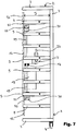
- the handle 7 is preferably positioned centrally on the drive auxiliary frame 12 as viewed along the horizontal direction. It forms from there two also to the left and right in the horizontal direction protruding handlebars or handlebar sections 24. Die Ends of these handle bar sections have a distance of less than or equal to 1/4 of the width of the cloth loader from the horizontal directly opposite horizontal guide rods 5. In this way, the operator can stand laterally next to the cloth loader 1 and pass through between two horizontal guide rods 5. He comfortably reaches the lying in the vicinity of these two guide rods grip portion and can move the handle 7 by means of the auxiliary drive back and forth well, see. also Fig. 7 ,
- the handle is not attached directly to the cloth slide or the drive auxiliary frame 12, but via a torsion section 25.
- This torsion 25 preferably includes the sensor not shown here.
- the sensor generates a signal which depends on how strongly the torsion section 25 is twisted under the influence of the forces applied to the handle 7.
- the sensor can also detect in which direction is twisted and provide corresponding signals.
- the grip portion of the handlebar 24 is not directly connected to the torsion portion 25. Rather, an intermediate, separate lever arm 26 is used.
- This lever arm 26 can be set on the design side, that the force applied by the operator on the handle 7 in the context of moving the slide sheath forces really cause such a pronounced torsion on the torsion 25, that the torsion occurring 25 torsions are correct in the working range of the sensor and therefore let it be addressed with the necessary accuracy.
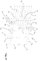
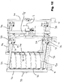
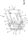
- the Fig. 10 . 11 . 12 and 13 show a second embodiment of the invention.
- the second exemplary embodiment of the cloth loader according to the invention corresponds to the first exemplary embodiment of the cloth loader according to the invention described so far.
- the foregoing therefore applies accordingly for this second embodiment, unless the differences described below necessarily require otherwise.
- the base frame 2 which is advantageously formed again as a cuboid and is preferably equipped with the length and width ratios, which have already been described for the first embodiment.
- the base frame 2 here again forms a shelf cart, on which a plurality of cloth slides 6 is arranged one above the other.
- the base frame 2 is preferably formed from rods or tubes 3. It then forms a substantially cuboid tubular frame.
- vertical rods or vertical tubes 3a are used which have a larger cross section or diameter than the horizontal rods or horizontal tubes 3b.
- no horizontal bar or horizontal tube is preferably attached at the bottom / no transversely or at right angles to the displacement direction. This avoids a dangerous stumbling block for the operator, who pushes the towel slide towards the oven by pushing on handle bar 24, which in turn activates the auxiliary drive, and tends to follow or follow the handle bar.
- a transverse / perpendicular to the direction of sliding (s) horizontal bar or horizontal tube is mounted on the same front side of the deck car above, which is set higher and thereby lies above the upper horizontal tubes or horizontal bars 3, which are parallel to the direction of displacement.
- a kind of door or portal is formed, which is high enough to ensure that the operator following the handlebar 24 into the floor trolley does not hit his head.
- the difference to the first embodiment here is that instead of the horizontal guide rods 5 for each sheath slide 6, preferably only a total of four horizontal guide rods 5a are provided. At least two or all four of the guide rods 5a are preferably not designed as separate components, but an integral part of a horizontal bar or a horizontal tube 3b.
- the lower guide rods 5a are ideally as separate components executed in addition to and separately from the lower horizontal bars or horizontal tubes 3b executed above the same.
- the drive auxiliary frame 12 is preferably made of a single, one or more parts, vertically extending column 28. This column carries - preferably only two - horizontally extending wheel bearing rods 29. The wheel bearing rods are on both sides of the column.
- the pillar is fixed to the wheel bearing rods 29 substantially or preferably completely centrally on the wheel bearing rods.
- the drive auxiliary frame 12 is thereby preferably as an H-shaped structure of the vertically extending column 28 and the two wheel bearing rods 29.
- the drive auxiliary frame 12 thus extends substantially in the vertical direction. Its maximum extent in the vertical direction is preferably greater by at least a factor of 4, better by at least a factor of 5, than its maximum horizontal extent parallel to its direction of travel.
- the drive auxiliary frame 12 carries the auxiliary drive 17, which, as also described above, preferably from motor 14, battery 21, electronics 18 and the drive pulses generating handlebar 24 and usually also a transmission 15, 20 consists.
- At least one or better at least one pair of guide rods 5a is equipped with a form-locking profile, preferably in the form of a toothed rack 23, in which corresponding form-fitting rollers, preferably pinions, engage the drive auxiliary frame 12 so that it can drive back and forth without a slip and mostly not only drive, but preferably also be able to slow down.
- each wheel bearing rod At the outermost end of each wheel bearing rod at least one guide roller is mounted, preferably even a guide roller set of at least two guide rollers, one of which may be the already mentioned pinion.
- the guide rollers run on the horizontal guide rods 5a.
- the guide roller set ensures that the guide rods 5a can not only absorb pressure forces from the drive auxiliary frame 12, but can also apply tensile forces and / or that the drive auxiliary frame 12 at least not be excavated relative to the guide rods 5a and can not tilt. Thereby, any torque acting on the drive auxiliary frame 12 can be absorbed by the guide rollers via the guide rods 5a. Because each guide roller set has at least one guide roller 30 which rests on top of the guide rods 5a and at least one other roller 30 which abuts against the guide rod 5a from below.
- Each guide roller set can be held by means of a guide roller box 31 at the end of the wheel bearing rod 29.
- a guide roller box 31 may consist of two parallel plates 32 which receive the guide rollers 30 between them each with an axis extending between the two plates 32.
- the column has couplings 30.
- a cloth slide 6 are coupled, preferably in that it is hooked into the respective coupling 30, which may preferably have the shape of a open at its upper end bayonet opening for this purpose.
- the couplings 30 are ideally realized by providing a U-profile which vertically oriented to the column 28 of the drive auxiliary frame 12 is mounted and in each of its two U-legs has the said upwardly open bayonet openings, which form a coupling 30 in pairs.
- a horizontal transverse support 33 can be provided for each slide valve 6, which supports it from below directly or via plain bearing sections attached thereto.
- the transverse support could, in direct contact, have a rotatable jacket over which the respective towel slide rolls.
- a form-fitting locking bar 34 On the oven side in the intended use furnace side can be provided vertically movable up and down a form-fitting locking bar 34. In its lowered position, it prevents a single cloth slide can be lifted out of the shelf trolley, z. B. in that it has a downwardly open, U-shaped claw for each slide slide 6, which engages positively over the lateral side wall of a drape. In its raised, released position, the interlocking bar 34 releases the slide shuttles 6 so that they can be lifted and removed for cleaning purposes.
- the oven locking device is particularly useful to perform the oven locking device as a pivotable about a horizontal axis hook bolt.
- the hook bolt has on its furnace near side an insertion bevel which raises when hitting the edge of the corresponding latch hole in the oven so that it can be easily inserted into the bolt hole. There, it ideally lowers under the influence of its own weight and locks so.
- the special design of the auxiliary drive frame has in this embodiment the advantage that the auxiliary drive frame as compared to the base frame with simple means roll or ball bearing support / load pickup for the cloth slide 6 itself can not serve directly to the base frame mounted towel slide in the field of auxiliary drive frame.
- the auxiliary drive frame captures a substantial portion of the weight of the towel slide 6 and possibly its charge and diverts it into the base frame - with towel slides fully retracted into the base frame, preferably at least about 40% to 60%.
- the scraper itself need not have its own role or ball bearing over the base frame, which saves considerable construction costs and, above all, simplifies cleaning.
- a cloth loader 1 which is characterized in that the handle 7 and the grip rod to be gripped on it lies at the height between two directly horizontal horizontal guide rods 5.
- a cloth loader 1 which is characterized in that the handle (7) is positioned centrally on the drive auxiliary frame 12 and forms therefrom from two left and right projecting handle bars whose distance from the horizontal guide rods 5 less than 1 ⁇ 4 of the width of the cloth loader. 1 is.
- the open side is preferably facing up.
- the electronic drive control 18 comprises one or preferably a plurality of electronic circuit breakers, which cause a variable pulse modulation of the motor supply current.
- auxiliary drive 17 comprises a motor 14 with a reduction gear 15, possibly in addition to said transfer case 27th
- a cloth loader 1 which is characterized in that the motor 14 is a permanent magnetically excited motor 14.
- Drive unit in particular also isolated, claiming protection on its own, for moving a plurality of cloth shuttles 6 relative to the base frame 2 of a cloth loader 1, consisting of a drive auxiliary frame 12, which carries an auxiliary drive 17 for moving the drive auxiliary frame 12 relative to the base frame 2 and an electronic drive control 18, and which is characterized in that the drive auxiliary frame 12 has a flange surface for connection to a plurality of cloth slides 6, such that the drive auxiliary frame 12 with the cloth slides 6 relative to the base frame 2 moves back and forth.
- Drive unit which is characterized in that on the drive auxiliary frame 12 there is mounted a handle 7 traveling with it which comprises a sensor which detects the force with which an operator pulls or pushes on the handle 7 and in dependence thereon provides a signal that controls the auxiliary drive 17.
- Drive unit according to one of the two preceding paragraphs, which is characterized in that the drive unit has further features relating to them of claims 1 to 23.
Landscapes
- Life Sciences & Earth Sciences (AREA)
- Engineering & Computer Science (AREA)
- Food Science & Technology (AREA)
- Handcart (AREA)
Priority Applications (1)
| Application Number | Priority Date | Filing Date | Title |
|---|---|---|---|
| PL17208259T PL3335565T3 (pl) | 2016-12-16 | 2017-12-18 | Ładowarka tkaninowa z napędem pomocniczym |
Applications Claiming Priority (1)
| Application Number | Priority Date | Filing Date | Title |
|---|---|---|---|
| DE202016107090.2U DE202016107090U1 (de) | 2016-12-16 | 2016-12-16 | Tuchlader mit Hilfsantrieb |
Publications (2)
| Publication Number | Publication Date |
|---|---|
| EP3335565A1 true EP3335565A1 (fr) | 2018-06-20 |
| EP3335565B1 EP3335565B1 (fr) | 2020-04-22 |
Family
ID=60673896
Family Applications (1)
| Application Number | Title | Priority Date | Filing Date |
|---|---|---|---|
| EP17208259.6A Active EP3335565B1 (fr) | 2016-12-16 | 2017-12-18 | Chargeur a bande textile pourvu d'un entraînement auxiliaire |
Country Status (3)
| Country | Link |
|---|---|
| EP (1) | EP3335565B1 (fr) |
| DE (1) | DE202016107090U1 (fr) |
| PL (1) | PL3335565T3 (fr) |
Citations (4)
| Publication number | Priority date | Publication date | Assignee | Title |
|---|---|---|---|---|
| DE1197043B (de) * | 1959-06-27 | 1965-07-22 | Werner & Pfleiderer | Beschickungsvorrichtung fuer Backoefen |
| DE202004011473U1 (de) | 2004-07-22 | 2004-09-16 | Karl Heuft Gmbh | Backofensystem mit Steinplattenwagen |
| WO2007051645A2 (fr) * | 2005-11-04 | 2007-05-10 | Heuft Besitzgesellschaft Gmbh & Co. Kg | Systeme de four a chariot enfourneur/defourneur automatise |
| DE202008014112U1 (de) * | 2008-10-23 | 2009-01-15 | Karl Ahlborn Maschinenfabrik Kg | Vorrichtung zum Verfahren von Tuchabziehapparaten auf einem Beschickungswagen |
-
2016
- 2016-12-16 DE DE202016107090.2U patent/DE202016107090U1/de not_active Expired - Lifetime
-
2017
- 2017-12-18 PL PL17208259T patent/PL3335565T3/pl unknown
- 2017-12-18 EP EP17208259.6A patent/EP3335565B1/fr active Active
Patent Citations (4)
| Publication number | Priority date | Publication date | Assignee | Title |
|---|---|---|---|---|
| DE1197043B (de) * | 1959-06-27 | 1965-07-22 | Werner & Pfleiderer | Beschickungsvorrichtung fuer Backoefen |
| DE202004011473U1 (de) | 2004-07-22 | 2004-09-16 | Karl Heuft Gmbh | Backofensystem mit Steinplattenwagen |
| WO2007051645A2 (fr) * | 2005-11-04 | 2007-05-10 | Heuft Besitzgesellschaft Gmbh & Co. Kg | Systeme de four a chariot enfourneur/defourneur automatise |
| DE202008014112U1 (de) * | 2008-10-23 | 2009-01-15 | Karl Ahlborn Maschinenfabrik Kg | Vorrichtung zum Verfahren von Tuchabziehapparaten auf einem Beschickungswagen |
Also Published As
| Publication number | Publication date |
|---|---|
| DE202016107090U1 (de) | 2018-03-18 |
| EP3335565B1 (fr) | 2020-04-22 |
| PL3335565T3 (pl) | 2020-11-02 |
Similar Documents
| Publication | Publication Date | Title |
|---|---|---|
| EP2011761B1 (fr) | Chariot de manutention, en particulier empileuse à fourche | |
| DE102017112658A1 (de) | Logistikfahrzeug | |
| EP1501702A2 (fr) | Plancher de chargement pour un vehicule et dispositif de chargement | |
| DE4227609A1 (de) | Vorrichtung zum raumsparenden Abstellen von Kraftfahrzeugen | |
| EP3318431B1 (fr) | Remorque de train de remorques | |
| DE3504491A1 (de) | Vorrichtung zum anlegen von bogen | |
| EP2507046A2 (fr) | Presse dotée d'au moins un chariot collecteur pouvant être couplé et désaccouplé | |
| DE2409284A1 (de) | Automatische stapelvorrichtung zum lageweisen stapeln von staeben, insbesondere walzprofilen | |
| DE69303173T2 (de) | Regalbedienungsgrät mit gabeln dopplter reichweite | |
| DE69416440T2 (de) | Automatisch geführtes Fahrzeug | |
| DE10140958A1 (de) | Regallager mit Schiebern in den Regalfächern | |
| EP3609835A1 (fr) | Chariot de manutention à système de poussée | |
| DE102009047297A1 (de) | Presse mit mindestens einem an- und abkoppelbaren Sammelwagen | |
| DE10158298C1 (de) | Einrichtung und Verfahren zum Drehen von Frachtpaletten in Luftfahrzeugen | |
| EP3335565B1 (fr) | Chargeur a bande textile pourvu d'un entraînement auxiliaire | |
| DE2259273A1 (de) | Vorrichtung zum umsetzen von stueckgut aus einer rollenbahn | |
| EP1103494B1 (fr) | Système de stockage pour palettes | |
| DE4325446C2 (de) | Regalbediengerät mit Gegengewichtsanordnung und einem einzigen Antriebsmittel für Hub- und Senkbewegung | |
| DE102004002548B3 (de) | Wechseleinheit für die Batterie eines Flurförderzeugs | |
| DE2321543B2 (de) | Etagen-backofen | |
| DE970587C (de) | Transportwagen fuer Kraftfahrzeuge | |
| EP3037377B1 (fr) | Chariot gerbeur, systeme de changement de batterie comprenant un chariot gerbeur et procede de changement de batterie de chariot gerbeur | |
| DE102012112319B4 (de) | Belade- und Entladevorrichtung zum Be- und Entladen von Regalen | |
| DE102021215077A1 (de) | Lager- und Entnahmesystem sowie Arbeitsplatz für ein Lager- und Entnahmesystem | |
| DE29515556U1 (de) | Anordnung zur Übergabe von Teigstücken |
Legal Events
| Date | Code | Title | Description |
|---|---|---|---|
| PUAI | Public reference made under article 153(3) epc to a published international application that has entered the european phase |
Free format text: ORIGINAL CODE: 0009012 |
|
| STAA | Information on the status of an ep patent application or granted ep patent |
Free format text: STATUS: THE APPLICATION HAS BEEN PUBLISHED |
|
| AK | Designated contracting states |
Kind code of ref document: A1 Designated state(s): AL AT BE BG CH CY CZ DE DK EE ES FI FR GB GR HR HU IE IS IT LI LT LU LV MC MK MT NL NO PL PT RO RS SE SI SK SM TR |
|
| AX | Request for extension of the european patent |
Extension state: BA ME |
|
| STAA | Information on the status of an ep patent application or granted ep patent |
Free format text: STATUS: REQUEST FOR EXAMINATION WAS MADE |
|
| 17P | Request for examination filed |
Effective date: 20180724 |
|
| RBV | Designated contracting states (corrected) |
Designated state(s): AL AT BE BG CH CY CZ DE DK EE ES FI FR GB GR HR HU IE IS IT LI LT LU LV MC MK MT NL NO PL PT RO RS SE SI SK SM TR |
|
| GRAP | Despatch of communication of intention to grant a patent |
Free format text: ORIGINAL CODE: EPIDOSNIGR1 |
|
| STAA | Information on the status of an ep patent application or granted ep patent |
Free format text: STATUS: GRANT OF PATENT IS INTENDED |
|
| INTG | Intention to grant announced |
Effective date: 20190529 |
|
| GRAJ | Information related to disapproval of communication of intention to grant by the applicant or resumption of examination proceedings by the epo deleted |
Free format text: ORIGINAL CODE: EPIDOSDIGR1 |
|
| STAA | Information on the status of an ep patent application or granted ep patent |
Free format text: STATUS: REQUEST FOR EXAMINATION WAS MADE |
|
| GRAP | Despatch of communication of intention to grant a patent |
Free format text: ORIGINAL CODE: EPIDOSNIGR1 |
|
| STAA | Information on the status of an ep patent application or granted ep patent |
Free format text: STATUS: GRANT OF PATENT IS INTENDED |
|
| INTC | Intention to grant announced (deleted) | ||
| INTG | Intention to grant announced |
Effective date: 20191104 |
|
| GRAS | Grant fee paid |
Free format text: ORIGINAL CODE: EPIDOSNIGR3 |
|
| GRAA | (expected) grant |
Free format text: ORIGINAL CODE: 0009210 |
|
| STAA | Information on the status of an ep patent application or granted ep patent |
Free format text: STATUS: THE PATENT HAS BEEN GRANTED |
|
| AK | Designated contracting states |
Kind code of ref document: B1 Designated state(s): AL AT BE BG CH CY CZ DE DK EE ES FI FR GB GR HR HU IE IS IT LI LT LU LV MC MK MT NL NO PL PT RO RS SE SI SK SM TR |
|
| REG | Reference to a national code |
Ref country code: CH Ref legal event code: EP |
|
| REG | Reference to a national code |
Ref country code: IE Ref legal event code: FG4D Free format text: LANGUAGE OF EP DOCUMENT: GERMAN |
|
| REG | Reference to a national code |
Ref country code: DE Ref legal event code: R096 Ref document number: 502017004839 Country of ref document: DE |
|
| REG | Reference to a national code |
Ref country code: AT Ref legal event code: REF Ref document number: 1258864 Country of ref document: AT Kind code of ref document: T Effective date: 20200515 |
|
| REG | Reference to a national code |
Ref country code: LT Ref legal event code: MG4D |
|
| REG | Reference to a national code |
Ref country code: NL Ref legal event code: MP Effective date: 20200422 |
|
| REG | Reference to a national code |
Ref country code: DE Ref legal event code: R082 Ref document number: 502017004839 Country of ref document: DE Representative=s name: MISSELHORN, MARTIN, DIPL.-ING., DE Ref country code: DE Ref legal event code: R081 Ref document number: 502017004839 Country of ref document: DE Owner name: BAECKEREI SERVICE PEUCKMANN GMBH & CO. KG, DE Free format text: FORMER OWNER: BAECKEREI SERVICE PEUCKMANN GMBH & CO. KG, 33415 VERL, DE |
|
| PG25 | Lapsed in a contracting state [announced via postgrant information from national office to epo] |
Ref country code: NL Free format text: LAPSE BECAUSE OF FAILURE TO SUBMIT A TRANSLATION OF THE DESCRIPTION OR TO PAY THE FEE WITHIN THE PRESCRIBED TIME-LIMIT Effective date: 20200422 Ref country code: PT Free format text: LAPSE BECAUSE OF FAILURE TO SUBMIT A TRANSLATION OF THE DESCRIPTION OR TO PAY THE FEE WITHIN THE PRESCRIBED TIME-LIMIT Effective date: 20200824 Ref country code: LT Free format text: LAPSE BECAUSE OF FAILURE TO SUBMIT A TRANSLATION OF THE DESCRIPTION OR TO PAY THE FEE WITHIN THE PRESCRIBED TIME-LIMIT Effective date: 20200422 Ref country code: GR Free format text: LAPSE BECAUSE OF FAILURE TO SUBMIT A TRANSLATION OF THE DESCRIPTION OR TO PAY THE FEE WITHIN THE PRESCRIBED TIME-LIMIT Effective date: 20200723 Ref country code: NO Free format text: LAPSE BECAUSE OF FAILURE TO SUBMIT A TRANSLATION OF THE DESCRIPTION OR TO PAY THE FEE WITHIN THE PRESCRIBED TIME-LIMIT Effective date: 20200722 Ref country code: FI Free format text: LAPSE BECAUSE OF FAILURE TO SUBMIT A TRANSLATION OF THE DESCRIPTION OR TO PAY THE FEE WITHIN THE PRESCRIBED TIME-LIMIT Effective date: 20200422 Ref country code: IS Free format text: LAPSE BECAUSE OF FAILURE TO SUBMIT A TRANSLATION OF THE DESCRIPTION OR TO PAY THE FEE WITHIN THE PRESCRIBED TIME-LIMIT Effective date: 20200822 Ref country code: SE Free format text: LAPSE BECAUSE OF FAILURE TO SUBMIT A TRANSLATION OF THE DESCRIPTION OR TO PAY THE FEE WITHIN THE PRESCRIBED TIME-LIMIT Effective date: 20200422 |
|
| PG25 | Lapsed in a contracting state [announced via postgrant information from national office to epo] |
Ref country code: HR Free format text: LAPSE BECAUSE OF FAILURE TO SUBMIT A TRANSLATION OF THE DESCRIPTION OR TO PAY THE FEE WITHIN THE PRESCRIBED TIME-LIMIT Effective date: 20200422 Ref country code: BG Free format text: LAPSE BECAUSE OF FAILURE TO SUBMIT A TRANSLATION OF THE DESCRIPTION OR TO PAY THE FEE WITHIN THE PRESCRIBED TIME-LIMIT Effective date: 20200722 Ref country code: LV Free format text: LAPSE BECAUSE OF FAILURE TO SUBMIT A TRANSLATION OF THE DESCRIPTION OR TO PAY THE FEE WITHIN THE PRESCRIBED TIME-LIMIT Effective date: 20200422 Ref country code: RS Free format text: LAPSE BECAUSE OF FAILURE TO SUBMIT A TRANSLATION OF THE DESCRIPTION OR TO PAY THE FEE WITHIN THE PRESCRIBED TIME-LIMIT Effective date: 20200422 |
|
| PG25 | Lapsed in a contracting state [announced via postgrant information from national office to epo] |
Ref country code: AL Free format text: LAPSE BECAUSE OF FAILURE TO SUBMIT A TRANSLATION OF THE DESCRIPTION OR TO PAY THE FEE WITHIN THE PRESCRIBED TIME-LIMIT Effective date: 20200422 |
|
| REG | Reference to a national code |
Ref country code: DE Ref legal event code: R097 Ref document number: 502017004839 Country of ref document: DE |
|
| PG25 | Lapsed in a contracting state [announced via postgrant information from national office to epo] |
Ref country code: ES Free format text: LAPSE BECAUSE OF FAILURE TO SUBMIT A TRANSLATION OF THE DESCRIPTION OR TO PAY THE FEE WITHIN THE PRESCRIBED TIME-LIMIT Effective date: 20200422 Ref country code: DK Free format text: LAPSE BECAUSE OF FAILURE TO SUBMIT A TRANSLATION OF THE DESCRIPTION OR TO PAY THE FEE WITHIN THE PRESCRIBED TIME-LIMIT Effective date: 20200422 Ref country code: SM Free format text: LAPSE BECAUSE OF FAILURE TO SUBMIT A TRANSLATION OF THE DESCRIPTION OR TO PAY THE FEE WITHIN THE PRESCRIBED TIME-LIMIT Effective date: 20200422 Ref country code: EE Free format text: LAPSE BECAUSE OF FAILURE TO SUBMIT A TRANSLATION OF THE DESCRIPTION OR TO PAY THE FEE WITHIN THE PRESCRIBED TIME-LIMIT Effective date: 20200422 Ref country code: RO Free format text: LAPSE BECAUSE OF FAILURE TO SUBMIT A TRANSLATION OF THE DESCRIPTION OR TO PAY THE FEE WITHIN THE PRESCRIBED TIME-LIMIT Effective date: 20200422 Ref country code: IT Free format text: LAPSE BECAUSE OF FAILURE TO SUBMIT A TRANSLATION OF THE DESCRIPTION OR TO PAY THE FEE WITHIN THE PRESCRIBED TIME-LIMIT Effective date: 20200422 |
|
| PG25 | Lapsed in a contracting state [announced via postgrant information from national office to epo] |
Ref country code: SK Free format text: LAPSE BECAUSE OF FAILURE TO SUBMIT A TRANSLATION OF THE DESCRIPTION OR TO PAY THE FEE WITHIN THE PRESCRIBED TIME-LIMIT Effective date: 20200422 |
|
| PLBE | No opposition filed within time limit |
Free format text: ORIGINAL CODE: 0009261 |
|
| STAA | Information on the status of an ep patent application or granted ep patent |
Free format text: STATUS: NO OPPOSITION FILED WITHIN TIME LIMIT |
|
| 26N | No opposition filed |
Effective date: 20210125 |
|
| PG25 | Lapsed in a contracting state [announced via postgrant information from national office to epo] |
Ref country code: SI Free format text: LAPSE BECAUSE OF FAILURE TO SUBMIT A TRANSLATION OF THE DESCRIPTION OR TO PAY THE FEE WITHIN THE PRESCRIBED TIME-LIMIT Effective date: 20200422 |
|
| REG | Reference to a national code |
Ref country code: CH Ref legal event code: PL |
|
| PG25 | Lapsed in a contracting state [announced via postgrant information from national office to epo] |
Ref country code: MC Free format text: LAPSE BECAUSE OF FAILURE TO SUBMIT A TRANSLATION OF THE DESCRIPTION OR TO PAY THE FEE WITHIN THE PRESCRIBED TIME-LIMIT Effective date: 20200422 |
|
| REG | Reference to a national code |
Ref country code: BE Ref legal event code: MM Effective date: 20201231 |
|
| PG25 | Lapsed in a contracting state [announced via postgrant information from national office to epo] |
Ref country code: IE Free format text: LAPSE BECAUSE OF NON-PAYMENT OF DUE FEES Effective date: 20201218 Ref country code: FR Free format text: LAPSE BECAUSE OF NON-PAYMENT OF DUE FEES Effective date: 20201231 Ref country code: LU Free format text: LAPSE BECAUSE OF NON-PAYMENT OF DUE FEES Effective date: 20201218 |
|
| PG25 | Lapsed in a contracting state [announced via postgrant information from national office to epo] |
Ref country code: LI Free format text: LAPSE BECAUSE OF NON-PAYMENT OF DUE FEES Effective date: 20201231 Ref country code: CH Free format text: LAPSE BECAUSE OF NON-PAYMENT OF DUE FEES Effective date: 20201231 |
|
| PG25 | Lapsed in a contracting state [announced via postgrant information from national office to epo] |
Ref country code: TR Free format text: LAPSE BECAUSE OF FAILURE TO SUBMIT A TRANSLATION OF THE DESCRIPTION OR TO PAY THE FEE WITHIN THE PRESCRIBED TIME-LIMIT Effective date: 20200422 Ref country code: MT Free format text: LAPSE BECAUSE OF FAILURE TO SUBMIT A TRANSLATION OF THE DESCRIPTION OR TO PAY THE FEE WITHIN THE PRESCRIBED TIME-LIMIT Effective date: 20200422 Ref country code: CY Free format text: LAPSE BECAUSE OF FAILURE TO SUBMIT A TRANSLATION OF THE DESCRIPTION OR TO PAY THE FEE WITHIN THE PRESCRIBED TIME-LIMIT Effective date: 20200422 |
|
| PG25 | Lapsed in a contracting state [announced via postgrant information from national office to epo] |
Ref country code: MK Free format text: LAPSE BECAUSE OF FAILURE TO SUBMIT A TRANSLATION OF THE DESCRIPTION OR TO PAY THE FEE WITHIN THE PRESCRIBED TIME-LIMIT Effective date: 20200422 |
|
| PG25 | Lapsed in a contracting state [announced via postgrant information from national office to epo] |
Ref country code: BE Free format text: LAPSE BECAUSE OF NON-PAYMENT OF DUE FEES Effective date: 20201231 |
|
| GBPC | Gb: european patent ceased through non-payment of renewal fee |
Effective date: 20211218 |
|
| PG25 | Lapsed in a contracting state [announced via postgrant information from national office to epo] |
Ref country code: GB Free format text: LAPSE BECAUSE OF NON-PAYMENT OF DUE FEES Effective date: 20211218 |
|
| PGFP | Annual fee paid to national office [announced via postgrant information from national office to epo] |
Ref country code: CZ Payment date: 20221205 Year of fee payment: 6 |
|
| PGFP | Annual fee paid to national office [announced via postgrant information from national office to epo] |
Ref country code: PL Payment date: 20221208 Year of fee payment: 6 |
|
| PGFP | Annual fee paid to national office [announced via postgrant information from national office to epo] |
Ref country code: DE Payment date: 20221221 Year of fee payment: 6 |
|
| REG | Reference to a national code |
Ref country code: AT Ref legal event code: MM01 Ref document number: 1258864 Country of ref document: AT Kind code of ref document: T Effective date: 20221218 |
|
| PG25 | Lapsed in a contracting state [announced via postgrant information from national office to epo] |
Ref country code: AT Free format text: LAPSE BECAUSE OF NON-PAYMENT OF DUE FEES Effective date: 20221218 |
|
| PG25 | Lapsed in a contracting state [announced via postgrant information from national office to epo] |
Ref country code: AT Free format text: LAPSE BECAUSE OF NON-PAYMENT OF DUE FEES Effective date: 20221218 |
|
| REG | Reference to a national code |
Ref country code: DE Ref legal event code: R119 Ref document number: 502017004839 Country of ref document: DE |
|
| PG25 | Lapsed in a contracting state [announced via postgrant information from national office to epo] |
Ref country code: CZ Free format text: LAPSE BECAUSE OF NON-PAYMENT OF DUE FEES Effective date: 20231218 |
|
| PG25 | Lapsed in a contracting state [announced via postgrant information from national office to epo] |
Ref country code: CZ Free format text: LAPSE BECAUSE OF NON-PAYMENT OF DUE FEES Effective date: 20231218 |
|
| PG25 | Lapsed in a contracting state [announced via postgrant information from national office to epo] |
Ref country code: DE Free format text: LAPSE BECAUSE OF NON-PAYMENT OF DUE FEES Effective date: 20240702 |
|
| PG25 | Lapsed in a contracting state [announced via postgrant information from national office to epo] |
Ref country code: DE Free format text: LAPSE BECAUSE OF NON-PAYMENT OF DUE FEES Effective date: 20240702 |
|
| PG25 | Lapsed in a contracting state [announced via postgrant information from national office to epo] |
Ref country code: PL Free format text: LAPSE BECAUSE OF NON-PAYMENT OF DUE FEES Effective date: 20231218 |
|
| PGFP | Annual fee paid to national office [announced via postgrant information from national office to epo] |
Ref country code: AT Payment date: 20260410 Year of fee payment: 5 |